

Page 1

Instruction Manual
HASX2E-IM-HS
02/2012
Gas Analyzers
X-STREAM X2 Series
Instruction Manual
www.EmersonProcess.com
Page 2

ESSENTIAL INSTRUCTIONS
READ THIS PAGE BEFORE PROCEEDING!
Emerson Process Management (Rosemount Analytical) designs, manufactures and
tests its products to meet many national and international standards. Because these
instruments are sophisticated technical products, you MUST properly install, use, and
maintain them to ensure they continue to operate within their normal specications.
The following instructions MUST be adhered to and integrated into your safety program
when installing, using and maintaining Emerson Process Management (Rosemount
Analytical) products. Failure to follow the proper instructions may cause any one of the
following situations to occur: Loss of life; personal injury; property damage; damage to
this instrument; and warranty invalidation.
• Read all instructions prior to installing, operating, and servicing the product.
• If you do not understand any of the instructions, contact your Emerson Process
Management (Rosemount Analytical) representative for clarication.
• Follow all warnings, cautions, and instructions marked on and supplied with the
product.
• Inform and educate your personnel in the proper installation, operation, and
maintenance of the product.
• Install your equipment as specied in the Installation Instructions of the
appropriate Instruction Manual and per applicable local and national codes.
Connect all products to the proper electrical and pressure sources.
• To ensure proper performance, use qualied personnel to install, operate, update,
program, and maintain the product.
• When replacement parts are required, ensure that qualied people use replacement
parts specied by Emerson Process Management (Rosemount Analytical).
Unauthorized parts and procedures can affect the product’s performance, place the
safe operation of your process at risk, and VOID YOUR WARRANTY. Look-alike
substitutions may result in re, electrical hazards, or improper operation.
• Ensure that all equipment doors are closed and protective covers are in place,
except when maintenance is being performed by qualied persons, to prevent
electrical shock and personal injury.
The information contained in this document is subject to change without notice.
10th edition, 02/2012
X-STREAM and IntrinzX are marks of one of the Emerson group of companies.
All other marks are property of their respective owners.
Rosemount Analytical
Process Gas Analyzer Center of Excellence
Emerson Process Management GmbH & Co. OHG
Industriestrasse 1
D-63594 Hasselroth
Deutschland
T +49 (0) 6055 884-0
F +49 (0) 6055 884-209
www.emersonprocess.de
Page 3

Instruction Manual
HASX2E-IM-HS
02/2012
SHORT FORM GUIDE FOR THIS MANUAL
X-STREAM X2
To nd information about see chapter
Safety instructions ..................................................... S
The different instruments designs
The instruments technical data
Measuring principles characteristics
How to install the instruments
st
startup procedures,
1
.............................1
..................................2
........................3
...................................4
checking the instrument´s setup ..............................5
Software menu structure, how to navigate
and menu entries descriptions
Basic procedures (e.g. calibration)
..................................6
............................7
Table of contents
TOC
Maintenance procedures
Status messages and troubleshooting
Modbus parameters
Service information
....................................................10
Block diagrams, terminals & connectors
Index of phrases
Emerson Process Management GmbH & Co. OHG TOC-1
........................................................IDX
............................................7
.....................8
...................................................9
................. A
Page 4

Instruction Manual
X-STREAM X2
HASX2E-IM-HS
02/2012
Table of ConTenTs
Introduction S-1
Denitions S-1
Terms Used in This Instruction Manual .........................................S-2
Symbols Used on and Inside the Unit
Symbols Used in This Manual ................................................S-4
Safety Instructions S-5
Intended Use Statement..................................................... S-5
General Safety Notice / Residual Risk ..........................................S-5
Authorized Personnel.......................................................S-6
Additional Literature . . . . . . . . . . . . . . . . . . . . . . . . . . . . . . . . . . . . . . . . . . . . . . . . . . . . . . . . S-6
Installing and Connecting the Unit .............................................S-7
Operating and Maintaining This Unit ........................................... S-7
.......................................... S-3
Chapter 1 Technical Description 1-1
1.1 Overview .............................................................1-3
1.1.1 The Front Panel.......................................................1-3
1.2 Conguration of Gas Lines ...............................................1-4
1.2.1 Materials Used .......................................................1-4
1.2.2 Safety Filter..........................................................1-4
1.2.3 Inlets and Outlets .....................................................1-4
1.2.4 Pipework ............................................................1-4
1.2.5 Infallible Containments .................................................1-4
1.2.6 Optional Components for Gas Lines.......................................1-5
1.2.7 Alternative Congurations ...............................................1-8
1.3 Interfaces.............................................................1-9
1.3.1 Analog Outputs .......................................................1-9
1.3.2 Status Relays ........................................................1-9
1.3.3 Optional Interfaces ...................................................1-10
1.4 Comparison of the Various X-STREAM Analyzer Models .......................1-12
1.5 X-STREAM X2GK: ½19 Inch Table-Top Unit.................................1-14
1.6 X-STREAM X2GP: 19 Inch Table-Top or Rackmount Design ....................1-17
1.7 X-STREAM X2XF: Field Housing With (XLF) Single Or (XXF) Dual Compartment....1-20
1.7.1 Field Housing for Installation in Hazardous Areas (Ex-Zones) ..................1-26
1.8 X-STREAM X2FD: Cast Aluminum Flameproof Housing........................1-27
Chapter 2 Technical Data 2-1
2.1 Common Technical Data .................................................2-2
2.2 Model-Specic Technical Data.............................................2-5
Emerson Process Management GmbH & Co. OHGTOC-2
Page 5

Instruction Manual
HASX2E-IM-HS
02/2012
Table of Contents
2.2.1 X-STREAM X2GK: ½19 Inch Table-Top Unit.................................2-5
2.2.2 X-STREAM X2GP: 19 Inch Table-Top and Rack-Mount Models ................2-12
2.2.3 X-STREAM X2XF: Single (XLF) or Dual (XXF) Compartment Field Housing.......2-15
2.2.4 X-STREAM X2FD: Flameproof Housing...................................2-19
2.3 Information on Name Plate ..............................................2-22
X-STREAM X2
Table of contents
Chapter 3 Measuring Principles 3-1
3.1 Infrared Measurement (IR), Ultraviolet Measurement (UV).......................3-1
3.1.1 IntrinzX Technology....................................................3-1
3.1.2 NDIR Detector........................................................3-3
3.1.3 Technical Implementation ...............................................3-4
3.2 Oxygen Measurement ...................................................3-5
3.2.1 Paramagnetic Measurement.............................................3-5
3.2.2 Electrochemical Measurement ...........................................3-8
3.2.3 Electrochemical Trace Oxygen Measurement...............................3-11
3.3 Thermal Conductivity Measurement .......................................3-13
3.3.1 Principle of Operation .................................................3-13
3.3.2 Technical Implementation ..............................................3-14
3.4 Trace Moisture Measurement ............................................3-15
3.4.1 Special Operating Conditions ...........................................3-16
3.4.2 Accompanying Gases .................................................3-17
3.5 Measurement Specications .............................................3-19
Chapter 4 Installation 4-1
4.1 Scope of Supply........................................................4-1
4.2 Introduction ...........................................................4-2
4.3 Gas Conditioning .......................................................4-3
4.4 Gas Connections .......................................................4-5
4.5 Electrical Connections ...................................................4-7
4.6 Analyzer Specic Instructions for Installation..................................4-8
4.6.1 X-STREAM X2GK.....................................................4-9
4.6.2 X-STREAM X2GP....................................................4-15
4.6.3 X-STREAM X2XF Field Housings (single XLF; Dual XXF).....................4-23
4.7 Notes On Wiring Signal Inputs and Outputs .................................4-34
4.7.1 Electrical Shielding of Cables ...........................................4-34
4.7.2 Wiring Inductive Loads ................................................4-37
4.7.3 Driving High-Current Loads.............................................4-37
4.7.4 Driving Multiple Loads.................................................4-38
TOC
Chapter 5 Startup 5-1
5.1 Introduction ...........................................................5-1
Emerson Process Management GmbH & Co. OHG TOC-3
Page 6

Instruction Manual
X-STREAM X2
Table of Contents
5.2 Front Panel Elements ...................................................5-2
5.2.1 Display..............................................................5-3
5.2.2 Status LED ..........................................................5-3
5.2.3 Keys 5-4
5.3 Symbols Used .........................................................5-6
5.4 Software..............................................................5-7
5.4.1 Navigating and Editing .................................................5-7
5.4.2 Access Levels ........................................................5-9
5.4.3 Special Messages....................................................5-10
5.5 Powering Up .........................................................5-11
5.5.1 Boot Sequence ......................................................5-11
5.5.2 Measurement Display .................................................5-11
5.6 Selecting the Language.................................................5-12
5.7 Checking the Settings ..................................................5-13
5.7.1 Installed Options .....................................................5-14
5.7.2 Conguring the Display................................................5-16
5.7.3 Calibration Setup.....................................................5-17
5.7.4 Setting the Analog Outputs .............................................5-20
5.7.5 Setting Concentration Alarms ...........................................5-28
5.7.6 Backing Up the Settings ...............................................5-34
HASX2E-IM-HS
02/2012
Chapter 6 User Interface and Software Menus 6-1
6.1 Symbols Used .........................................................6-2
6.2 Menu System..........................................................6-3
6.2.1 Startup..............................................................6-4
6.2.2 Control Menu.........................................................6-5
6.2.3 Setup Menu.........................................................6-14
6.2.4 Status Menu ........................................................6-50
6.2.5 Info Menu ..........................................................6-61
Chapter 7 Maintenance and Other Procedures 7-1
7.1 Introduction ...........................................................7-1
7.2 General Maintenance Information ..........................................7-2
7.3 Performing a Leak Test ..................................................7-4
7.4 Calibration Procedures ..................................................7-5
7.4.1 Preparing Calibrations..................................................7-7
7.4.2 Manual Calibration ...................................................7-17
7.4.3 Advanced Calibration .................................................7-20
7.4.4 Remote Calibration ...................................................7-31
7.4.5 Unattended Automatic Calibration........................................7-36
Emerson Process Management GmbH & Co. OHGTOC-4
Page 7

Instruction Manual
HASX2E-IM-HS
02/2012
Table of Contents
7.4.6 Resetting a Calibration ................................................7-39
7.4.8 Cancelling an Ongoing Calibration .......................................7-40
7.5 Replacing Worn Out Sensors ............................................7-42
7.5.1 Safety Instructions....................................................7-42
7.5.2 Opening X-STREAM Analyzers..........................................7-43
7.5.3 Replacing the Electrochemical Oxygen Sensor .............................7-46
7.5.4 Replacing the Trace Oxygen Sensor......................................7-53
7.5.5 Replacing the Trace Moisture Sensor.....................................7-54
7.6 Cleaning the Instrument´s Outside ........................................7-55
7.7 Save / Restore Conguration Data Sets ....................................7-56
7.7.1 Save CfgData to UserData .............................................7-58
7.7.2 Restore UserData to CfgData ...........................................7-59
7.7.3 Copy FactData to CfgData .............................................7-60
7.7.4 Save / Restore CfgData to External Device ................................7-61
X-STREAM X2
Table of contents
TOC
Chapter 8 Troubleshooting 8-1
8.1 Abstract ..............................................................8-1
8.2 Solving Problems Indicated by Status Messages ..............................8-2
8.2.1 Analyzer Related Messages .............................................8-3
8.2.2 Channel Related Messages (preceded by Channel Tag, e.g. CO2.1) .............8-6
8.3 Solving Problems Not Indicated by Status Messages.........................8-11
8.4 Troubleshooting on Components..........................................8-17
8.4.1 Opening X-STREAM Analyzers .........................................8-19
8.4.2 Signal Connectors on XSP Board........................................8-21
8.4.3 Sample Pump: Replacement of Diaphragm ................................8-22
8.4.4 Paramagnetic Oxygen Cell: Adjustment of Physical Zero......................8-33
8.4.5 Thermal Conductivity Cell: Adjustment of Output Signal.......................8-36
Chapter 9 Modbus Functions 9-1
9.1 Abstract ..............................................................9-1
9.1.1 Modbus TCP/IP .......................................................9-1
9.2 Supported Functions ....................................................9-2
9.3 List of Parameters and Registers - Sorted by Tag Name.........................9-2
9.4 List of Parameters and Registers - Sorted by Daniel Registers...................9-22
Chapter 10 Service Information 10-1
10.1 Return of Material .....................................................10-1
10.2 Customer Service .....................................................10-2
10.3 Training .............................................................10-2
Emerson Process Management GmbH & Co. OHG TOC-5
Page 8

Instruction Manual
X-STREAM X2
Table of Contents
HASX2E-IM-HS
02/2012
Chapter 11 Dismounting and Disposal 11-1
11.1 Dismounting and Diposal of the Analyzer ...................................11-1
Appendix A-1
A.1 Modbus Specication...................................................A-2
A.2 EC Declaration of Conformity ...........................................A-12
A.3 CSA Certicate of Compliance...........................................A-14
A.4 Block Diagram .......................................................A-21
A.5 Water Vapor: Relationship of Dewpoint, Vol.-% and g/Nm³..................... A-34
A.6 Declaration of Decontamination..........................................A-35
A.7 Assignment of Terminals and Sockets..................................... A-37
Index I-1
Emerson Process Management GmbH & Co. OHGTOC-6
Page 9

Instruction Manual
HASX2E-IM-HS
02/2012
X-STREAM X2
Table of figures
Fig. 1-1: X-STREAM Front Panel (here the X-STREAM X2GP) ...........................................1-3
Fig. 1-2: Optional Heated Area .............................................................................................1-7
Fig. 1-3: Gas Flow Diagram: Single Channel or in Series ....................................................1-8
Fig. 1-4: Serial Interface Marking ........................................................................................1-10
Fig. 1-5: X-STREAM X2GK - Views ....................................................................................1-16
Fig. 1-6: X-STREAM X2GP - Views ....................................................................................1-19
Fig. 1-7: X-STREAM X2XF Field Housings - Front Views ..................................................1-22
Fig. 1-8: X-STREAM X2XF Field Housings - Front Panel ..................................................1-23
Fig. 1-9: X-STREAM XLF - Bottom and Side View .............................................................1-24
Fig. 1-10: X-STREAM XLF - Power Supply and Signal Terminals ........................................1-25
Fig. 1-11: X-STREAM X2FD - Front View ............................................................................1-29
Fig. 1-12: X-STREAM X2FD - Front Panel ...........................................................................1-30
Fig. 1-13: X-STREAM X2FD - Bottom View ..........................................................................1-30
Fig. 1-14: X-STREAM X2FD - Terminals ..............................................................................1-31
Table of contents
TOC
Fig. 2-1: X-STREAM X2GK - Dimensions ............................................................................2-5
Fig. 2-2: X-STREAM X2GK - Rear Panel and Handle Variations .........................................2-6
Fig. 2-3: UPS 01 T Power Supply Unit ..................................................................................2-9
Fig. 2-4: 10 A Table-Top PSU ..............................................................................................2-10
Fig. 2-5: X-STREAM X2GP - Dimensions ...........................................................................2-12
Fig. 2-6: X-STREAM X2GP - Power Supply and Signal Connections ................................2-14
Fig. 2-7: X-STREAM X2GP - Signal Connections With Screw-Type Terminal Adapters ....2-14
Fig. 2-8: X-STREAM XLF - Dimensions .............................................................................2-15
Fig. 2-9: X-STREAM XXF - Dimensions .............................................................................2-16
Fig. 2-10: X-STREAM X2XF Field Housings - Power Supply Terminals / Fuse Holders ......2-18
Fig. 2-11: X-STREAM X2XF Field Housings - Signal Terminals .........................................2-18
Fig. 2-12: X-STREAM X2FD - Dimensions ...........................................................................2-19
Fig. 2-13: X-STREAM X2FD - Power Supply Terminals / Fuse Holders ...............................2-20
Fig. 2-14: X-STREAM X2FD - Signal Terminals ...................................................................2-21
Fig. 2-15: Analyzer Name Plate (examples) .........................................................................2-22
Fig. 3-1: IntrinzX Signal Forms .............................................................................................3-2
Fig. 3-2: Gas Detector Design Principle ...............................................................................3-3
Fig. 3-3: Photometer Assembly Principle ..............................................................................3-4
Fig. 3-4: Paramagnetic Oxygen Sensor - Assembly Principle ..............................................3-5
Fig. 3-5: Electrochemical Sensor - Assembly Principle ........................................................ 3-8
Fig. 3-6: Electrochemical O2 Sensor - Assembly ..................................................................3-8
Fig. 3-7: Electrochemical Reaction of Oxygen Sensor ........................................................3-9
Emerson Process Management GmbH & Co. OHG TOC-7
Page 10

Instruction Manual
X-STREAM X2
HASX2E-IM-HS
02/2012
Index of Figures
Fig. 3.8 Cover for EO2 Sensor Block At Rear Panel .........................................................3-10
Fig. 3.9 Trace Oxygen Sensor Design Principle ................................................................3-11
Fig. 3.10 Cover for TO2 Sensor Block At Rear Panel ..........................................................3-12
Fig. 3-11: Wheatstone Bridge ...............................................................................................3-13
Fig. 3-12: TC Cell, Exterior View, Thermal Isolation Removed .............................................3-14
Fig. 3-13: TC Cell, Sectional View ........................................................................................3-14
Fig. 3-14: Trace Moisture Sensor Assembly .........................................................................3-15
Fig. 4-1: X-STREAM X2 Analyzers - Scope of Supply ..........................................................4-1
Fig. 4-3: Installation in Bypass Mode ....................................................................................4-6
Fig. 4-2: Labelling of Gas Connectors (example) .................................................................4-6
Fig. 4-4: X-STREAM X2GK - Front Panel .............................................................................4-9
Fig. 4-5: X-STREAM X2GK - Rear Panel ...........................................................................4-10
Fig. 4-6: Socket X1 - Pin Conguration ..............................................................................4-11
Fig. 4-7: Plug X2 - Modbus Interface ..................................................................................4-12
Fig. 4-8: Socket X4 - Pin Conguration .............................................................................4-13
Fig. 4-9: Power In Connectors ............................................................................................4-14
Fig. 4-10: X-STREAM X2GP - Front View ............................................................................4-15
Fig. 4-11: X-STREAM X2GP - Rear Panel, Model With Signal Plugs and Sockets..............4-16
Fig. 4-12: X-STREAM X2GP - Rear Panel, With Terminal Adapters and Brackets ..............4-17
Fig. 4-13: Socket X1 - Analog & Digital Outputs 1-4 ............................................................4-18
Fig. 4-14: Plug X2 - Modbus Interface ..................................................................................4-19
Fig. 4-15: Conguration of XSTA Terminal Adapter ..............................................................4-20
Fig. 4-16: Sockets X4.1 and X4.2 - Pin Conguration .........................................................4-21
Fig. 4-17: Conguration of XSTD Terminal Adapter ..............................................................4-22
Fig. 4-18: X-STREAM XLF ..................................................................................................4-23
Fig. 4-19: X-STREAM XXF ..................................................................................................4-24
Fig. 4-20: X-STREAM X2XF Field Housings - Terminals, Cable Glands and Gas Fittings ...4-25
Fig. 4-21: Terminal Block X1 - Analog Signals and Relay Outputs 1-4 ................................4-28
Fig. 4-22: Terminal Block X1 - Modbus Interface ..................................................................4-29
Fig. 4-23: X-STREAM X2XF Field Housings - Ethernet Connector ......................................4-30
Fig. 4-24: Terminal Blocks for Digital Inputs and Outputs .....................................................4-31
Fig. 4-25: Power Supply Connections ..................................................................................4-32
Fig. 4-26: Shielded Signal Cable, Shielding Connected At Both Ends. ................................4-34
Fig. 4-27: Shielded Signal Cable, Shielding Connected At One end. ...................................4-35
Fig. 4-28: Signal Cable With Double Shielding, Shieldings Connected At Alternate Ends. ..4-35
Fig. 4-29: Shield Connector Terminal With Cable .................................................................4-36
Fig. 4-30: Suppressor Diode for Inductive Loads. ................................................................4-37
Fig. 4-31: Driving High-Current Loads ..................................................................................4-37
Emerson Process Management GmbH & Co. OHGTOC-8
Page 11

Instruction Manual
HASX2E-IM-HS
02/2012
Index of Figures
Fig. 4-32: Loads in Series .....................................................................................................4-38
Fig. 4-33: Loads in Parallel ...................................................................................................4-38
Fig. 5-1: X-STREAM Front Panel .........................................................................................5-2
Fig. 5-2: Limits Dening a Window for Valid Concentrations ..............................................5-31
Fig. 5-3: High Pre-Alarm and Main Alarm ...........................................................................5-32
Fig. 5-4: Low Pre-Alarm and Main Alarm ............................................................................5-33
Fig. 6-1: X-STREAM Software Menu Structure ....................................................................6-3
Fig. 7-1: Leak Testing With U-Turn Manometer ....................................................................7-4
Fig. 7-2: Calibration Improvement by Variable Valve Assignments .....................................7-10
Fig. 7-3: Internal Valves Assignments .................................................................................7-13
Fig. 7-4: Zero All Calibration Procedure Flow Chart ........................................................... 7-22
Fig. 7-5: Span All Calibration Procedure Flow Diagram ..................................................... 7-25
Fig. 7-6: Zero Span All Calibration Procedure Flow Diagram .............................................7-28
Fig. 7-7: Digital Inputs - Initializing Calibrations ..................................................................7-33
Fig. 7-8: Graphical Explanation of Interval Time Settings ...................................................7-37
Fig. 7-9: X-STREAM X2GP .................................................................................................7-43
Fig. 7-10: X-STREAM X2GK ................................................................................................7-43
Fig. 7-11: X-STREAM X2 Field Housings and X2FD - How to Open ...................................7-44
Fig. 7-12: Location of the EO2 Sensor Unit ..........................................................................7-49
Fig. 7-13: Sensor Unit Design ...............................................................................................7-50
Fig. 7-14: Sensor At Rear Panel ...........................................................................................7-51
Fig. 7-15: OXS Board, Top View ...........................................................................................7-51
Fig. 7-16: Trace Moisture Sensor Assembly Separated .......................................................7-54
Fig. 7-17: Relationship of Supported Data Sets and Where to Find Further Information .....7-57
Fig. 7-18: Service Port Connector - Serial RS 232 Interface ................................................7-61
X-STREAM X2
Table of contents
TOC
Fig. 8-1: X-STREAM X2GP .................................................................................................8-19
Fig. 8-2: X-STREAM X2GK ................................................................................................8-19
Fig. 8-3: X-STREAM X2 Field Housings and X2FD - How to Open ...................................8-20
Fig. 8-4: XSP - Allocation of Signal Connectors..................................................................8-21
Emerson Process Management GmbH & Co. OHG TOC-9
Page 12

X-STREAM X2
Instruction Manual
HASX2E-IM-HS
02/2012
index of Tables
Tab. 3-1: Paramagnetic Sensor -
Tab. 3-2: Solvent Resistant Paramagnetic Sensor - Approved Solvents ...............3-7
Tab. 3-3: Solvent Resistant Paramagnetic Sensor - Medium Affected Materials ........3-7
Tab. 3-4: Electrochemical Oxygen Measurement -
Tab. 3-5: Examples of Specific Thermal Conductivities ...........................3-13
Tab. 3-6: Dew Points and Water Content (at 1013 HPa) ..........................3-16
Tab. 3-7: Limitations on Gases ..............................................3-17
Tab. 3-8: Gas Components and Measuring Ranges, Examples ....................3-19
Tab. 3-9: IR, UV, VIS, TCD - Measurement Performance Specifications ..............3-20
Tab. 3-10: Oxygen - Standard Measurement Performance Specifications .............3-21
Tab. 3-11: Trace Moisture - Standard Measurement Performance Specifications ........3-22
Tab. 3-12: Special Performance Specifications for Gas Purity Measurements ..........3-22
Tab. 5-1: Analog Output Signals - Settings and Operational Modes .................5-21
Tab. 5-2: Analog Outputs - Scaling (examples) .................................5-27
Tab. 5-3: Influence of “SpanRange” Parameter on Concentration Alarm Limits ........5-29
Tab. 6-1: Analog Output Signals: Settings and Operational Modes ..................6-32
Tab. 6-2: Options for Digital Outputs .........................................6-38
Tab. 6-3: Options for Digital Inputs ...........................................6-40
Tab. 6-4: Parameter IntSHS Options .........................................6-42
Cross Interferences (examples) .....................3-6
Cross Interference by Gases ........3-10
Tab. 7-1: Digital Inputs Priorities ............................................7-32
Emerson Process Management GmbH & Co. OHGTOC-10
Page 13
Instruction Manual
HASX2E-IM-HS
02/2012
X-STREAM X2
INTRODUCTION
The instruction manual contains information about the component assembly, function,
installation, operation and maintenance of the X-STREAM® X2 series gas analyzers.
The manual covers several X-STREAM analyzer models and so many contain information
about congurations and/or options not appliccable to your analyzer.
The installation and operation of units for use in explosive environments is not covered
in this manual.
Analyzers intended to be used in such environments are supplied with further instruction
manuals, which should be consulted in addition to this.
DEFINITIONS
The following denitions explain the use of the terms WARNING, CAUTION and NOTE in
this manual.
Safety Instructions
S
Indicates an operational or maintenance procedure, a process, a condition,
an instruction, etc.
Failure to comply may result in injury, death or permanent health risk.
Indicates an operational or maintenance procedure, a process, a condition,
an instruction, etc.
Failure to comply may result in damage to or destruction of the instrument,
or impaired performance.
NOTE!
Indicates an imperative operational procedure,
or an important condition or instruction.
Emerson Process Management GmbH & Co. OHG S-1
Page 14

X-STREAM X2
TERMS USED IN THIS INSTRUCTION MANUAL
Instruction Manual
HASX2E-IM-HS
02/2012
Explosive Gas(es)
Flammable Gases and gas mixtures in a mixture with air within the explosive limits.
Flammable Gas(es)
Gases and gas mixtures are assigned to be
ammable if they might become ignitable
when in a mixture with air.
Infallible Containment
This term is derived from the standards of
explosion protection especially from the requirements for pressurized housings: thus an
infallible containment can be characterized
by no intended leakage into the gas paths
enabling gas to enter the inner compartment
of the analyzer housing.
Intrinsically Safe Cell (IS Cell)
Cells supplied with an intrinsically safe power
signal, approved by a Test Institute, to operate
with explosive gases.
The design ensures the IS cells remains safe
even in case of failure and explosive gases
are not ignited.
Protection Class IP66 / NEMA 4X
Both terms are used to specify conditions for
equipment to be installed outdoor.
IP stands for Ingress Protection, the rst num-
ber species protection against solid objects
(6. = dust tight) while the second number
species the degree of protection against
liquids (.6 = heavy seas).
NEMA stands for National Electrical Manuf-
acturers Association. 4X species a degree
of protection to personnel against incidental
contact with the enclosed equipment; to provide a degree of protection against falling dirt,
rain, sleet, snow, windblown dust, splashing
water, and hose-directed water; and that will
be undamaged by the external formation of
ice on the enclosure
Upper Explosion Limit (UEL)
Volume ratio of ammable gas in air above
which an explosive gas atmosphere will not
be formed: the mixture of gas and air is too
rich in fuel (decient in oxygen) to burn.
Lower Explosion Limit (LEL)
Volume ratio of ammable gas in air below
which an explosive gas atmosphere will not
be formed: the mixture of gas and air lacks
sufcient fuel (gas) to burn.
NAMUR
NAMUR is an international user association of
automation technology in process industries.
This organisation has issued experience reports and working documents, called recommendations (NE) and worksheets (NA).
Emerson Process Management GmbH & Co. OHGS-2
Page 15
Instruction Manual
HASX2E-IM-HS
02/2012
X-STREAM X2
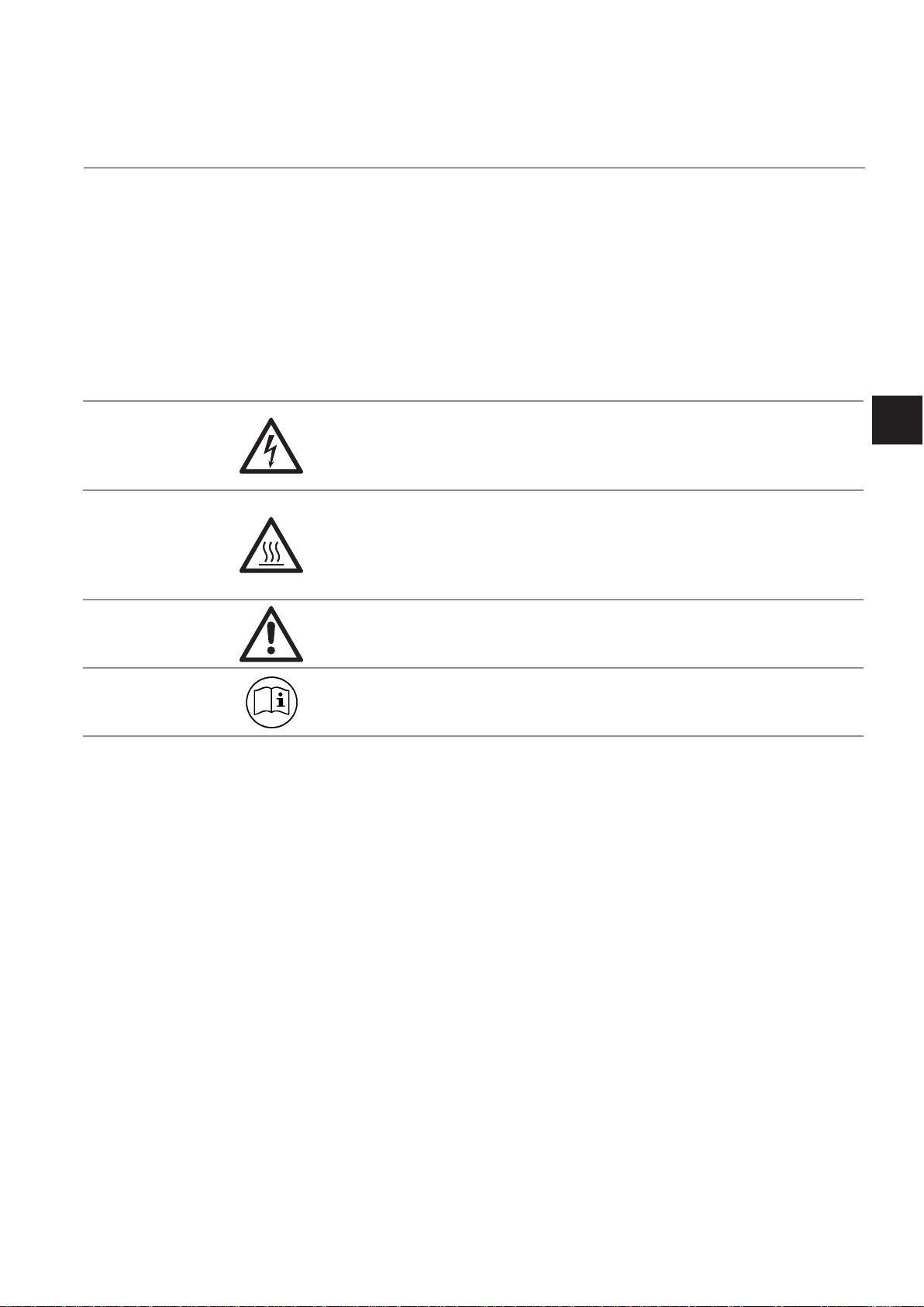
SYMBOLS USED ON AND INSIDE THE UNIT
Wherever one or more of the following symbols appear on or inside the instrument, be careful
and read the instructions given in the accompanying manuals!
Strictly observe the given warnings, instructions and information to minimize hazards!
This symbol at the instrument ... ... means
dangerous voltages may be accessible. Remo-
ving covers is permitted only, if the instrument is
disconnected from power - and even in this case
by qualied personnel only!
hot surfaces may be accessible. Removing
covers by qualied personnel is permitted only,
if the instrument is disconnected from power.
Nevertheless several surfaces may remain hot
for a limited time.
more detailled information available: see in-
struction manual before proceeding!
more detailled information available: see in-
struction manual before proceeding!
Safety Instructions
S
Emerson Process Management GmbH & Co. OHG S-3
Page 16
Instruction Manual
X-STREAM X2
HASX2E-IM-HS
02/2012
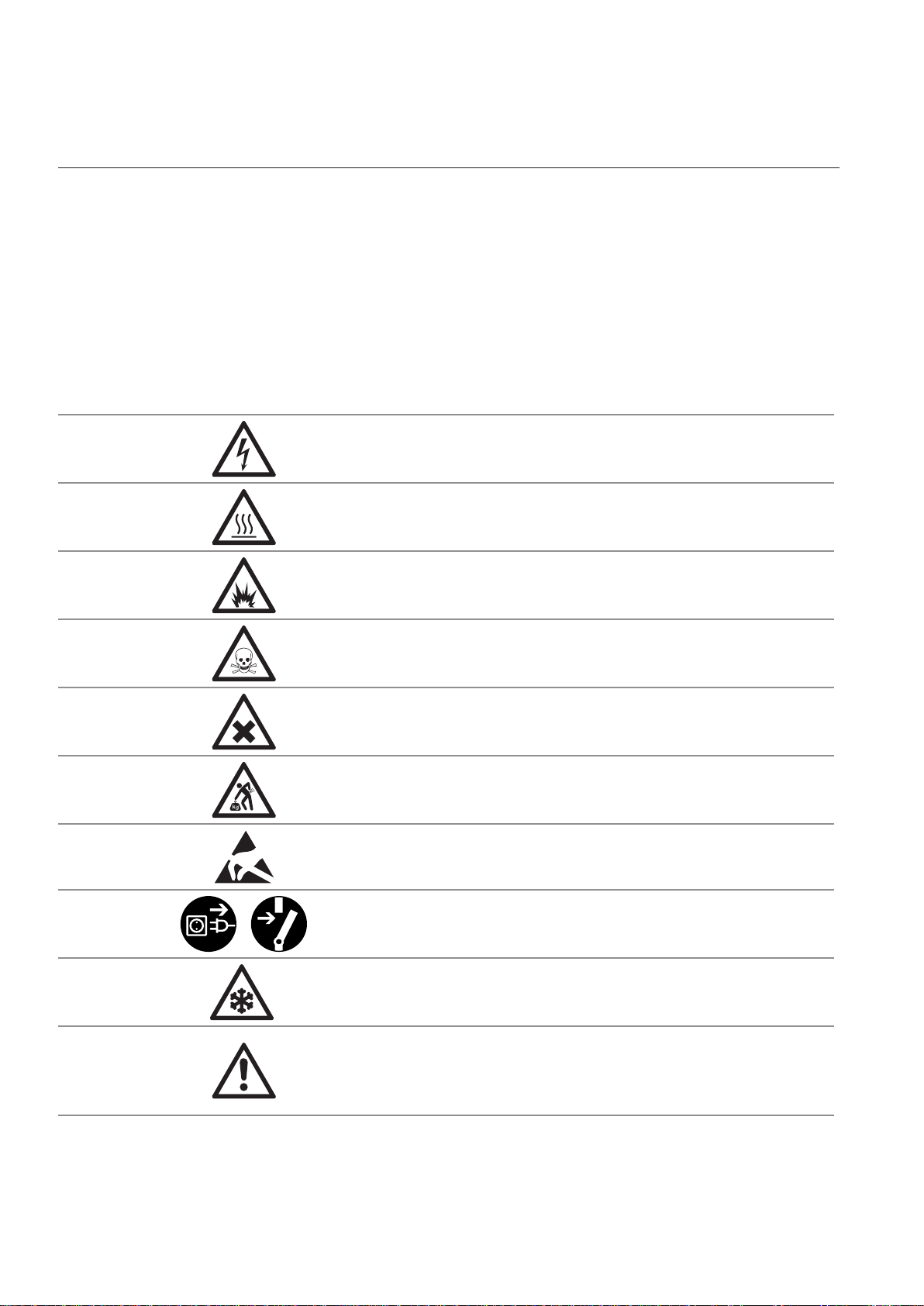
SYMBOLS USED IN THIS MANUAL
Wherever one or more of the following symbols are used in this instruction manual, read the
accompanying information and instructions carefully.
Follow these warnings and notes carefully
to minimize risk.
This symbol used in the manual ... ... means
dangerous voltages may be exposed
hot surfaces may be exposed
possible danger of explosion
toxic substances may be present
substances harmful to health may be present
indicates notes relating to heavy instruments
electrical components may be destroyed by
electrostatic discharges
units must be disconnected from the power
source
indicates special instructions or information for
operation at low temperatures.
indicates basic conditions or procedures are
being described.
This symbol may also indicate information impor-
tant for achieving accurate measurements.
Emerson Process Management GmbH & Co. OHGS-4
Page 17

Instruction Manual
HASX2E-IM-HS
02/2012
X-STREAM X2
SAFETY INSTRUCTIONS
INTENDED USE STATEMENT
X-STREAM series gas analyzers are intended to be used as analyzers for industrial purposes. They must not be used in medical, diagnostic or life support applications nor as
safety devices.
Using X-STREAM XE analyzers as safety devices, requiring redundant design or SIL clas-
sication, is also not permitted.
No independent agency certications or approvals are to be implied as covering such
applications!
Safety Instructions
S
GENERAL SAFETY NOTICE / RESIDUAL RISK
If this equipment is used in a manner not specied in these instructions, protective sy-
stems may be impaired.
Despite of incoming goods inspections, production control, routine tests and application
of state-of-the-art measuring and test methods, an element of risk remains when operating
a gas analyzer!
Even when operated as intended and observing all applicable safety instructions some
residual risks remain, including, but not limited to, the following:
• An interruption of the protective earth line, e.g. in an extension cable, may result in risk
to the user.
• Live parts are accessible when operating the instrument with doors open or covers
removed.
• The emission of gases hazardous to health may even be possible when all gas connections have been correctly made.
Avoid exposure to the dangers of these residual risks by taking particular care when installing, operating, maintaining and servicing the analyzer.
Emerson Process Management GmbH & Co. OHG S-5
Page 18

Instruction Manual
X-STREAM X2
Safety Instructions
HASX2E-IM-HS
02/2012
AUTHORIZED PERSONNEL
In-depth specialist knowledge is an absolutely necessary condition for working with and
on the analyzer.
Authorized personnel for installing, operating, servicing and maintaining the analyzer are
instructed and trained qualied personnel of the operating company and the manufacturer.
It is the responsibility of the operating company to
• train staff,
• observe safety regulations,
• follow the instruction manual.
Operators must
• have been trained,
• have read and understood all relevant sections of the instruction manual before
commencing work,
• know the safety mechanisms and regulations.
To avoid personal injury and loss of property, do not install, operate, maintain or service
this instrument before reading and understanding this instruction manual and receiving
appropriate training.
ADDITIONAL LITERATURE
This manual covers aspects important for installation and startup of X-STREAM X2 gas
analyzers.
For comprehensive information on operating and maintain/service the instrument in a
safe manner it is MANDATORY to read all additional instruction manuals! If not provided
as printed version, check for a accompanying USB stick with an electronic version (PDF)!
The following additional instruction manuals are available or referenced within this manual:
• HASX2E-SFM-HS X-STREAM X2 short form manual
• HASICx-IM-H Infallible containment instruction manual
• Separate manuals for Hazardous Area applications
Contact your local service center or sales ofce when missing documents.
SAVE ALL INSTRUCTIONS FOR FUTURE USE!
Emerson Process Management GmbH & Co. OHGS-6
Page 19

Instruction Manual
HASX2E-IM-HS
02/2012
Safety Instructions
X-STREAM X2
INSTALLING AND CONNECTING THE UNIT
The following notices should be carefollowed to ensure compliance with the low voltage directive.
1.
Suitable grounding connections should be made at all connectors provided for this purpose.
2. All safety covers and grounding connections must be properly reinstated after maintenance
work or troubleshooting.
3. A fuse should be provided at the installation site which will completely disconnect the unit
in case of failure. Installing an isolating switch may also be benecial. In either case, these
components must be constructed to conform to recognised norms.
Safety Instructions
S
OPERATING AND MAINTAINING THIS UNIT
On leaving our factory, this instrument confor-
med to all applicable safety directives.
In order to preserve this state of affairs, the
operator must take care to follow all the instructions and notes given in this manual and
on the unit.
Before switching on the unit, ensure that the
local nominal mains voltage corresponds to
the factory-set operational voltage of this
unit.
Any interruption of the protective earth connections, whether inside or outside of the unit,
may result in exposure to the risk of electricity .
Deliberately disconnected the protective earth
is therefore strictly forbidden.
Removing covers may expose components
conducting electric current. Connectors may
also be energised. The unit should therefore
be disconnected from the power supply before
any kind of maintenance, repair or calibration
work requiring access to the inside of the
unit.
Only trained personnel who are aware of
the risk involved may work on an open and
energized unit.
Fuses may only be replaced by fuses of an
identical type and with identical ratings. It is
forbidden to use repair fuses or to bypass
fuses.
Take note of all applicable regulations when
using this unit with an autotransformer or a
variable transformer.
Substances hazardous to health may escape
from the unit’s gas outlet. This may require
additional steps to be taken to guarantee the
safety of operating staff.
Emerson Process Management GmbH & Co. OHG S-7
Page 20
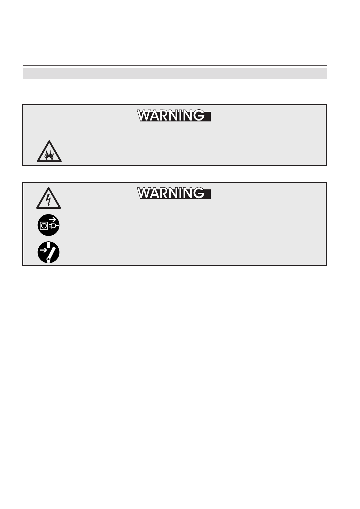
X-STREAM X2
The units described in this manual may not be used in explosive atmospheres
without additional safety measures.
Do not operate without covers secure. Do not open while energized.
Installation requires access to live parts which can cause death or serious
injury.
Instruction Manual
HASX2E-IM-HS
02/2012
Safety Instructions
EXPLOSION HAZARD
ELECTRICAL SHOCK HAZARD
For safety and proper performace this instrument must be connected to a
properly grounded three-wire source of power.
Emerson Process Management GmbH & Co. OHGS-8
Page 21
Instruction Manual
HASX2E-IM-HS
02/2012
This unit’s exhaust may contain toxic gases such as (but not limited
to) e.g. sulfur dioxide. These gases can cause serious injuries.
Avoid inhaling exhaust gases.
Connect the exhaust pipe to a suitable ue and inspect the pipes regularly
for leaks.
All connections must be airtight to avoid leaks. See section 7.2, page 7-2
for instructions on performing a leak test.
X-STREAM X2
Safety Instructions
TOXIC GASES
Safety Instructions
S
HEAVY INSTRUMENT
The models intended for outside and wall mounted use (X-STREAM XLF,
XXF and X2FD) weigh between 26 kg (57 lb) and 63 kg (139 lb), depending
on version and options installed.
Two people and/or lifting equipment is required to lift and carry these units.
Take care to use anchors and bolts specied to be used for the weight of
the units!
Take care the wall or stand the unit is intended to be installed at is solid
and stable to support the weight!
HIGH TEMPERATURES
Hot parts may be exposed when working on photometers and/or
heated components
in the unit.
Emerson Process Management GmbH & Co. OHG S-9
Page 22
X-STREAM X2
Safety Instructions
GASES AND PREPARATION OF GASES
GASES HAZARDOUS TO HEALTH
Follow the safety precautions for all gases (sample and span gases) and
gas cylinders.
Before opening the gas lines, they must be purged with air or neutral gas
) to avoid danger from escaping toxic, ammable, exposive or hazardous
(N
2
gases.
Instruction Manual
HASX2E-IM-HS
02/2012
EXPLOSIVE GASES
When supplying ammable gases with concentrations of more than ¼ of
the lower explosion limit, we RECOMMEND implementing one or more
additional safety measures:
• purging the unit with inert gas
• stainless steel internal pipes
• ame arrestors on gas inlets and outlets
• inherently safe or failsafe measuring cells
OPERATION AT LOW TEMPERATURES
When operating an instrument at temperatures below 0 °C (32 °F), do
NOT apply gas nor operate the internal pump before the warmup time has
elapsed!
Violation may result in condensation inside the gas paths or damaged pump
diaphragm!
Emerson Process Management GmbH & Co. OHGS-10
Page 23
Instruction Manual
HASX2E-IM-HS
02/2012
Power supply
X-STREAM X2
Safety Instructions
Ensure that the local power voltage where the unit is to be installed,
corresponds to the unit’s nominal voltage as given on the name plate
label.
CONNECTING UNITS FOR PERMANENT INSTALLATION
Only qualied personnel following all applicable and legal regulations
may install the unit and connect it to power and signal cables. Failure to
comply may invalidate the unit’s warranty and cause exposure to the risk
of damage, injury or death.
This unit may only be installed by qualied personnel familiar with the
possible risks.
Working on units equipped with screw-type terminals for electrical
connections may require the exposure of energized components.
Wall-mounted units have no power switch and are operational when
connected to a power supply . The operating company is therefore required
to have a power switch or circuit breaker (as per IEC 60947-1/-3) available
on the premises. This must be installed near the unit, easily accessible to
operators and labelled as a power cut-off for the analyzer.
Safety Instructions
S
ADDITIONAL NOTES FOR UNITS WITH SCREW-TYPE TERMINALS
Cables for external data processing must be double-insulated against mains
power.
If this is not possible, cables must be laid in such a way as to guarantee
a clearance of at least 5 mm from power cables. This clearance must be
permanently secured (e.g. with cable ties)
Emerson Process Management GmbH & Co. OHG S-11
Page 24
Instruction Manual
X-STREAM X2
HASX2E-IM-HS
02/2012
General Operating Notes
General operating notes
EXPLOSION HAZARD
Exhaust gases may contain hydrocarbons and other toxic gases such as
carbon monoxide. Carbon monoxide is toxic.
Faulty gas connections may lead to explosion and death.
Ensure that all gas connections are connected as labelled and airtight.
• The unit must be installed in a clean and dry area protected from strong vibrations and
frost
.
• The unit must not be exposed to direct sunlight and sources of heat. Admissable ambient
temperatures (see technical details) must be adhered to.
• Gas inlets and outlets must not be interchanged.All gases must be supplied to the unit already
processed. When using this unit with corrosive sample gases, ensure that these gases do
not contain components harmful to the gas lines.
• Admissable gas pressure for sample and test gases is 1500 hPa.
• Exhaust lines must be laid inclined downwards, depressurized, protected from frost and
according to applicable regulations.
• If it is necessary to disconnect the gas lines, the unit’s gas connectors must be sealed with
PVC caps to avoid polluting the internal gas lines with condensate, dust, etc.
• To ensure electromagnetic compatibility (EMC), only shielded cables (supplied by us on
request, or of equivalent standard) may be used. The customer must ensure that the shiel-
ding is correctly tted ( section 4.5, page 4-31). Shielding and terminal housing must be
electrically connected; submin-D plugs and sockets must be screwed to the unit.
• When using optional external adapters (submin-D to screw-type terminal), protection from
electromagnetic interference can no longer be guaranteed (CE compliance pursuant to EMC
guidelines). In this case the customer or operating company functions as a maker of a system
and must therefore ensure and declare compliance with EMC guidelines.
Emerson Process Management GmbH & Co. OHGS-12
Page 25

Instruction Manual
HASX2E-IM-HS
02/2012
X-STREAM X2
Chapter 1
Technical description
The following are the main features of the new
Emerson Process Management X-STREAM
gas analyzers in brief:
• compact design with easily accessible
internal components
• customizable for a wide range of applications: different housings are avail-
able while internal construction remains
largely identical
• multilingual microprocessor-controlled
user interface with liquid crystal (LCD)
or vacuum ourescent display (VFD) to
indicate measurement value and status
messages
• units for outdoor use are optionally supplied with an impact tested front panel
• widerange power supply unit for worldwi-
1
de use without modication (
⁄2 19in units
with internal or external PSUs)
X-STREAM X2 gas analyzers can measure
up to four different gas components by mul-
tiple combinations of the following analyzing
techniques (restrictions apply to ½19in units):
IR = non-dispersive infrared analysis
Special congurations (e.g. intrinsically safe
or infallible measuring cells) for the analysis
of combustible gases are also available.
Chapter 3 contains a detailed descrip-
tion of the various measuring techniques.
Standard applications
The use of different housings allow X-
STREAM analyzers to be tailored to the many
different applications:
• Tabletop units in ½19in modular design,
with IP 20 protection class
• Tabletop and rackmountable units in 19
in modular design, with IP 20 protection
class
• Stainless steel wallmountable field
housing with IP 66 / NEMA 4X protection
class for outdoor use (operating temperature -20°C to +50°C).
• Cast aluminium wallmountable field
housing with IP 66 / NEMA 4X protection
class for outdoor use (operating temperature -20°C to +50°C).
The various analyzer types are described in
more detail in section 1.4, page 1-12ff.
Technical Description
1
UV = ultraviolet analysis
pO
=
paramagnetic oxygen analysis
2
eO
=
electrochemical oxygen analysis
2
tO2 = electrochemical trace oxygen analysis
TC = thermal conductivity analysis
Installation in hazardous areas
X-STREAM analyzers in eld housings, when
tted with various protective devices, can
also be installed and operated in hazardous
environments. Available options are:
• Non-incendive assembly (Ex nA nC) for
tH
O = trace moisture measurement
2
Modied resistant measuring cells are avai-
installation in Zone 2 and Division 2 for the
measurement of non-ammable gases.
lable for use with corrosive gases and/or
gases containing solvents.
• Pressurized enclosure conforming to
ATEX directive 94/9/EC, for installation
in zone 2.
Emerson Process Management GmbH & Co. OHG 1-1
Page 26

X-STREAM X2
Instruction Manual
HASX2E-IM-HS
02/2012
1 Technical Description
• Simplified purge system (Z-purge) for
installation in North American Div 2 environments.
The cast aluminium eld housing (Ex d) is
designed to withstand an explosion and
intended to be used in hazardous areas of
Zone 1. Its robust design with NEMA 4X / IP
66 protection also enables the installation in
rough environments outside hazardous areas.
More information about analyzers for hazardous areas can
be obtained from your Emerson
Process Management sales
ofce.
Note!
These instructions do not detail the installa-
tion or operation of X-STREAM analyzers in
hazardous areas. If you intend to use your
analyzer for such purposes, we would
draw your attention to the separate instruction manuals supplied with analyzers
for use in hazardous areas.
Further features (in parts options):
• Congurable measurement display
• gas values and/or secondary measure-
ments (e. g. ow)
• single or dual pages
• Congurable measurement units
• supports conversion factors from ppm
to several other, even user specic units
• 3 independent software access levels
• protection against unauthorized chan-
ging of congurations
• password protected
• to be separately activated
• Unattended zero and span calibrations
• calibrations without user interaction
• Backup and restore analyzer congura-
tions to/from protected internal memory.
Emerson Process Management GmbH & Co. OHG1-2
Page 27
Instruction Manual
HASX2E-IM-HS
02/2012
1.1 Overview
X-STREAM X2
1.1 Overview
All X-STREAM gas analyzers feature an
easy-to-use alphanumeric user interface,
which displays measurement values, status
and error messages, and menus for the input
of parameters.
1.1.1 The Front Panel
All X-STREAM gas analyzers feature an
alphanumeric LCD display with 4x20 characters, showing measurement and status
information.
Wall-mounted units can, as an alternative, be
tted with a vacuum uorescent display, incre-
asing legibility in brighter environments.
The
display can also be protected with an impact
tested glass panel.
All analyzer types also feature three LEDs on
the front panel which display status information in addition to the plain text messages.
For ease of use, the operator can select one
of ve languages for the display (currently
available: English, French, German, Italian
and Spanish).
The colors of the LEDs are based on the
NAMUR NE 44 specifications. The LEDs
are activated in accordance with the NE 107
standards, and indicate “Failure”, “Function
check”, “Out of specication” and “Maintenance
request”. For further information, see
chapter 8, page 8-1.
The analyzer software is operated by means
of only six keys.
Technical Description
1
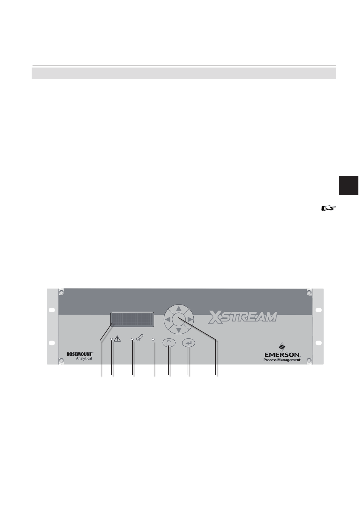
1 3 4 5 6 72
1 4x20 character alphanumeric display
2 LED (red)
3 LED (red)
4 LED (green)
Fig. 1-1: X-STREAM Front Panel (here the X-STREAM X2GP)
Emerson Process Management GmbH & Co. OHG 1-3
5 “Measure“ key
6 “Enter” key
7 4 keys for settings and menu navigation
Page 28

X-STREAM X2
Instruction Manual
HASX2E-IM-HS
02/2012
1.2 Conguration of Gas Lines
1.2 Configuration of Gas Lines
Various materials are available to allow the
analyzer to be customized to your needs.
The materials used are selected based on
the characteristics of the sample gas, e.g.
diffusion rate, corrosiveness, temperature
and pressure.
1.2.1 Materials Used
The physical and chemical properties of the
sample gas as well as the conditions under
which measurement takes place inuence the
choice of materials. Among those available
are Viton
®
, PFA and stainless steel.
1.2.2 Safety Filter
The analyzers are generally tted with an
internal stainless-steel lter. This lter is not
a replacement for any dust lter in the prepa-
ration of the gas, but represents a last line of
defence.
1.2.3 Inlets and Outlets
Rackmounted and tabletop devices are tted
with PVDF inlets and outlets (ø 6/4 mm) as
standard. Alternatively, Swagelok™ or stain-
less steel ttings (ø 6/4 mm or ¼ in can be
tted.
Wall-mounted eld housings are supplied
with Swagelok™ or stainless steel ttings (ø
6/4 mm or ¼ in) ausgestattet.
Other materials available on request.
X-STREAM X2FD units are always supplied
with ame arrestors and stainless steel ttings
(ø 6/4 mm or ¼ in).
1.2.4 Pipework
Unless otherwise specied, the analyzers
are supplied with Viton® or PVDF piping (ø
6/4 mm or ¼ in). Other materials (e.g. stain-
less steel) can be used, depending on the
application.
1.2.5 Infallible Containments
Infallible containments are gas lines which,
due to their design, can be regarded as per-
manently technically tight. This is achieved
by, for example, welded joints, or metallically
sealing joints (e.g. tap connectors and bin-
ders), providing they are seldom disconnec-
ted. Gas lines congured in this manner can
be used for measuring noxious, ammable
and explosive gases. At the time of going
to press, infallible containments for thermal
conductivity analysis (TC) are available; other
analysis methods are projected. Further in-
formation about infallible containments can
be found in the separate instruction manual
supplied with these units.
Infallible containments do not
render it unnecessary to test for
leaks regularly, e.g. following
lengthy breaks in service, substantial alterations, repairs and
modications.
Read the separate instruction
manual giving detailed instructions on the conguration, operation and maintenance of units
fitted with infallible containments.
Emerson Process Management GmbH & Co. OHG1-4
Page 29

Instruction Manual
HASX2E-IM-HS
02/2012
1.2 Conguration of Gas Lines
1.2.6 Optional Components for Gas Lines
X-STREAM X2
The analyzers can, as an option, be tted with
further components. Not all components are
available for all analyzer types:
• internal sample gas pump
• internal valve block
• internal ow sensors
• internal ow monitor switch
• internal barometric pressure meters
• internal temperature sensors.
1.2.6.1 Internal Sample Gas Pump
An internal sample gas pump is used when
the sample gas is under insufcient pressure.
It ensures a constant ow of sample gas (max.
2.5 l/min through the analyzer).
When in internal pump is tted, the relevant
parameter in the software setup dialog is set
to Yes ( 6.2.3.5, page 6-43). The pump
can be controlled either manually through a
software menu or optionally by a digital input.
1.2.6.2 Internal Valve Block
The use of an internal valve block allows all
necessary gas lines (zero gas, span gas,
sample gas) to remain permanently connected to the analyzer. Valves are then activated
automatically when required (e.g. during au-
tomatic calibration).
When an internal valve block is tted, this is
shown in the relevant software setup dialog
as either Internal or Int+Ext (
page 6-43). The valves are controlled by
either a software menu, optionally by digital
input, or automatically during autocalibration.
Depending on the model, up to two valve
bocks can be tted.
6.2.3.5,
1.2.6.3 Internal Flow Sensor
Up to two internal ow sensors can measure
the ow of gas and can activate an alarm si-
gnal in the event of a failure. The alarm level
for ow sensors is operator adjustable to up
to 2000 ml/min. Depending on the model, up
to two sensors can be tted and evaluated
separately.
When a sensor is tted, the relevant parame-
ter in the software setup dialog is set to Yes
(
6.2.3.5, page 6-43).
If the current ow rate is too low, a status
message is displayed and the parameter
under CHECK REQUESTS.. is set to Yes
( Chapter 8 “Troubleshooting”).
1.2.6.4 Internal Flow Monitor Switch
An internal ow switch monitors the gas ow
and activates an alarm signal in case it is not
sufcient. The alarm level for the internal ow
switch is xed and not operator adjustable.
Additional external switches may used and
connected via digital inputs. All tted ow
switches are evaluated to share a common
alarm.
When an internal ow switch is tted, the relevant parameter in the software setup dialog
is set to Yes (
If the current ow rate is too low, a status
message is displayed and the parameter
under CHECK REQUESTS.. is set to Yes
( Chapter 8 “Troubleshooting”).
6.2.3.5, page 6-43).
Technical Description
1
Emerson Process Management GmbH & Co. OHG 1-5
Page 30

X-STREAM X2
1.2 Conguration of Gas Lines
1.2.6.5 Internal Barometric Pressure Sensor
The inuence of varying atmospheric pres-
sure can be compensated for by the use of
an internal barometric pressure sensor (
measurement specication, page 3-17).
If such a sensor is installed in the unit, the
related menu shows the entry Internal (
6.2.3.5, page 6-43).
1.2.6.6 Internal Temperature Sensors
Instruction Manual
HASX2E-IM-HS
02/2012
The inuence of varying temperatures can
be compensated for by the use of internal
temperature sensors (
measurement
specication, page 3-17 ).
Depending on the conguration of the unit or
the demands of the application, temperature
sensors can measure the unit’s internal temperature or selected measurement channel
components.
If such sensors are installed in the unit, this is
indicated in the installed options menu (
6.2.3.5, page 6-43).
Emerson Process Management GmbH & Co. OHG1-6
Page 31

Instruction Manual
HASX2E-IM-HS
02/2012
1.2.6.7 Optional Heated Area
X-STREAM X2
1.2 Conguration of Gas Lines
The physical components can be optionally
separated from the electrical components
by means of a special box (not an option for
½ 19 in units). This can be done for one or
both of the following purposes:
Firstly, the box allows the physical components to be regulated to a temperature of ap-
prox. 60°C, avoiding condensation of gases
or the inuence of varying environmental
temperatures.
Secondly, the box can be purged with, for
example, inert gas. The purge gas is rst fed
through a separate tting, purges the elec-
tronic components, then oods the box and
leaves the instrument via another tting.
Purging in this manner can be useful when
measuring very low concentrations (e.g. of
CO or CO
): the expulsion of ambient air
2
avoids adulterant outside inuences.
Alternatively, purging can be used to secure
enhanced protection for electronic parts and
operators from corrosive or toxic gases: any
leaking gas is expelled from the housing and
does not escape into the vicinity of the unit or
come into contact with any electronic compo-
nents located outside the box.
In either case, the purge gas outlet should be
connected to an exhaust gas line.
Technical Description
1
Insulating cover
Physical
components
(example)
Heated mounting panel
The gure shows the heated
area with the insulating cover
removed.
Fig. 1-2: Optional Heated Area
Emerson Process Management GmbH & Co. OHG 1-7
Cable support for
signal wires
Page 32

X-STREAM X2
1.2 Conguration of Gas Lines
1.2.7 Alternative Configurations
Depending on the application and the selected
analyzer options, alternative gas line congurations are available, exemplied in the follo-
wing diagram of a dual-channel analyzer:
Instruction Manual
HASX2E-IM-HS
02/2012
Fig. 1-3: Gas Flow Diagram: Single Channel or in Series
Emerson Process Management GmbH & Co. OHG1-8
Page 33

Instruction Manual
HASX2E-IM-HS
02/2012
1.3 Interfaces
X-STREAM X2
1.3 Interfaces
All analyzer types are tted with one analog
electrical output for each channel and four
status relays as standard.
As an option, further interfaces can be added.
1.3.1 Analog Outputs
Each X-STREAM analyzer is tted with one
output per channel as standard, which can
transmit data on concentration levels to an
external data acquisition system.
The mode of operation (e.g. 4-20 mA,
0-20 mA) and support for NAMUR NE 43
specications (incl. Live Zero) can be set in a
software menu ( 5.7.4, page 5-20).
The factory setting for analog outputs is
4-20 mA.
Depending on the unit conguration, all in-
terfaces are accessible via either SubminD
connectors or screw terminals
.
X-STREAM analyzers support up to four analog outputs, which, however, do not always
need to be assigned to measurement channels which are physically present: if a unit has
less than four channels, the remaining analog
outputs can be used to transmit concentration
levels with a different resolution; for example,
a single-channel analyzer could be set up as
follows:
Output 1: 0…100 % CO
Output 2: 0…25 % CO
= 4…20 mA
2
= 4…20 mA
2
Technical Description
1
1.3.2 Status Relays
By default, the four relays are congured to
signal the current status of the unit according
to the
NAMUR NE 44 recommendations
(“Failure”, “Maintenance request”, “Out of
specication” and “Function check”). Howe-
ver , the operator can assign different functions
to the relays via software menus. For more
The contacts, which can take a maximum load
of 30 V at 1 A and 30 W, can be operated as
normally open or normally closed.
Further information on the status relays
is provided in the chapter “Technical Data”
2.1, pages 2-2 ff!
information, see 6.2.3.4.2, page 6-37 ff.
Note!
The NE 44 status is also indicated by the
LEDs on the front panel. These LEDs remain
conformant to NE 44 even when the status
relays are assigned different functions by the
software.
Emerson Process Management GmbH & Co. OHG 1-9
Page 34

X-STREAM X2
1.3 Interfaces
1.3.3 Optional Interfaces
1.3.3.1 Modbus Interface, Serial
A serial interface with the Modbus protocol
allows communication with external data ac-
quisition systems. The interface enables the
exchange and modication of measurement
and analyzer signals as well as the remote
activation of procedures.
The RS 485 interface is electrically isolated
from the unit’s electronic components and
facilitates the construction of a network of
several analyzers.
Optionally, an RS 232 interface can also be
used (and is also electrically isolated from
the unit’s electronic components; however,
it only allows communication between two
end devices.
Instruction Manual
HASX2E-IM-HS
02/2012
A table nearby the
connector shows the
interface conguration
(here: MODBUS)
X
Fig. 1-4: Serial Interface Marking
All supported Modbus parameters are listed
in chapter 9.
1.3.3.2 Modbus Interface, Ethernet
The Ethernet Modbus interface offers the
same form of comunication with a data acquisition system as does a serial interface.
The most obvious difference is the plug-and-
socket connection: the Ethernet interface
uses an RJ45 socket.
This interface is also electrically isolated from
the unit’s electronic components and enables the construction of a network of several
analyzers.
All supported Modbus parameters are listed
in chapter 9.
Note!
The Ethernet Modbus interface cannot be
combined with the serial Modbus interface
(
1.3.3.1).
Emerson Process Management GmbH & Co. OHG1-10
Page 35

Instruction Manual
HASX2E-IM-HS
02/2012
1.3.3.3 Digital Outputs
X-STREAM X2
1.3 Interfaces
Digital outputs can be used for various purposes:
• Issuing concentration alarms: Process
control systems can detect when limits
are exceeded and trigger appropriate
actions.
• Switching external components: For ex-
ample, during automatic calibration, the
necessary valves can be activated directly
by the analyzer.
1.3.3.4 Digital Inputs
Digital inputs can:
• trigger calibration procedures, for example
by a process control system
• remotely control valves and the optional
sample gas pump (in concert with correctly
congured digital outputs).
Digital inputs can be integrated into the units
in groups of 7 or 14 (
1.4, page 1-12).
Digital outputs can be integrated into the units
in groups of 9 or 18 (
1.4, page 1-12).
The relay contacts, which can take a maxi-
mum load of 30 V at 1 A and 30 W, can be
operated as normally open (NO) or normally
closed (NC).
Electrical details
LOW: U
HI2GC: U
≤ 1,5 V
in
≥ 4,5 V
in
Input impedence: 57,5 kΩ
Common ground for all outputs (“IN-GND”)
The inputs are protected against excess
voltages of up to approx. 40 V. An open (not
wired) input has LOW potential.
Technical Description
1
Emerson Process Management GmbH & Co. OHG 1-11
Page 36

X-STREAM X2
1.4 Overview of Analyzer Types
1.4 Comparison of the Various X-STREAM Analyzer Models
Instruction Manual
HASX2E-IM-HS
02/2012
X-STREAM X2GK
1
⁄219 in housing, table-top or rackmountable,
optional with carrying handle
1
⁄119 in housing, table-top or rackmountable,
protection type: IP 20
X-STREAM X2GP
protection type: IP 20
Internal wide range power supply, or
Internal wide range power supply unit Internal wide range power supply unit Internal wide range power supply unit
24V input with external power supply unit
Max. 3 channels in many combinations
max. 8 gas connections,
including 1 optional purge gas connection
Options for gas lines: Valve block, sample gas
pump, ow sensor, pressure sensor, infallible
gas lines
Max. 4 channels in any combination
max. 8 gas connections,
1 optional extra connection for purge gas
Options for gas lines: Flow sensor, pressu-
re sensor, heating for physical components,
sample gas pump, 1 or 2 valve blocks, infallible gas lines
1–4 analog outputs, 4 relay outputs
optional:
1 interface card with 7 digital inputs and
9 digital outputs
1 Modbus interface (serial or Ethernet)
electrical interfaces accessible via sockets on
back of unit
)
1–4 analog outputs, 4 relay outputs
optional:
1 or 2 interface cards, each with 7 digital
inputs and 9 digital outputs
1 Modbus interface (serial or Ethernet)
electrical interfaces accessible via sockets on
back of unit, optionally: screw-type terminal
adapters
(except for Ethernet)
LCD LCD LCD, optionally: vacuum uorescent display,
Operational ambient temperature:
0 °C to +50 °C (32 °F to 122 °F)
Available w/o front plate controls as module
XCC
Size: (DxHxW): max. ca. 460x128.7x213 mm
Weight: ca. 8–12 kg (17.6–26.5 lb)
For more detailed information:
section 1.5, page 1-14
Operational ambient temperature:
0 °C to +50 °C (32 °F to 122 °F)
Available w/o front plate controls as module
XCA
Size: (DxHxW): max. ca. 411x133x482 mm
Weight: ca. 11–16 kg (24–35 lb)
For more detailed information:
section 1.6, page 1-16
Emerson Process Management GmbH & Co. OHG1-12
Page 37

Instruction Manual
HASX2E-IM-HS
02/2012
X-STREAM X2XF X-STREAM X2FD
X-STREAM X2
1.4 Overview of Analyzer Types
Technical Description
Stainless steel wallmountable eldhousing,
tection type: IP66 / NEMA 4X
ingle (XLF) or dual (XXF) compartment design
S
Max. 4 channels in any combination
max. 8 gas connections,
1 optional extra connection for purge gas
Options for gas lines: Flow sensor, pressure
sensor, heating for physical components,
sample gas pump, 1 or 2 valve blocks, infallible gas lines
1–4 analog outputs, 4 relay outputs
optional:
1 or 2 interface cards, each with 7 digital
inputs and 9 digital outputs
1 Modbus interface (serial or Ethernet)
electrical interfaces on internal screw-type terminal adapters
impact tested front panel
(except for Ethernet)
pro-
Cast aluminium wallmountable eld housing,
protection type: IP66 / NEMA 4X
Max. 4 channels in any combination
max. 8 gas connections,
including 1 optional purge gas connection
Options for gas lines: Flow sensor, pressure sensor, heating for physical components,
sample gas pump, 1 or 2 valve blocks, infallible gas lines
1–4 analog outputs, 4 relay outputs
optional:
1 or 2 interface cards, each with 7 digital
inputs and 9 digital outputs
1 Modbus interface (serial or Ethernet)
electrical interfaces on internal screw-type terminal adapters
LCD, impact tested front panel
optionally: vacuum uorescent display
(except for Ethernet)
1
operational ambient temperature:
-20 °C to +50 °C (-4 °F to 122 °F)
Models available for use in explosive environ-
ments
Size: (DxHxW): max. ca. 222x460x520 mm
Weight: max. ca. 26 kg (57 lb)
For more detailed information:
section 1.7, page 1-19
Emerson Process Management GmbH & Co. OHG 1-13
operational ambient temperature:
-20 °C to +50 °C (-4 °F to 122 °F)
Flameproof enclosure: approved for use in ex-
plosive areas
Size: (DxHxW): max. ca. 222x512x578 mm
Weight: max. ca. 63 kg (138.5 lb)
For more detailed information:
section 1.8, page 1-26
Page 38

X-STREAM X2
1.5 X-STREAM X2GK
1.5 X-STREAM X2GK: ½19 Inch Table-Top Unit
Instruction Manual
HASX2E-IM-HS
02/2012
This compact model for general purposes
can be tted with up to three measurement
channels in various combinations. Power is
supplied by an internal wide range power sup-
ply or a separate external power supply unit.
By default the units are congured for tabletop
use. A carrying handle is optional available
which makes it easy to take the instrument to
varying sampling points. For rack mounting a
X2GK is xed by screws located at the front
panel.
Front panel
The analyzer’s front panel consists of one
4x20-character alphanumeric LCD display, a
membrane keyboard and three status LEDs
(Fig. 1-4). The colors of the LEDs are based on
the NAMUR NE 44 specications. The LEDs
are activated according to the NE 107 standards and correspond to the following status
messages: “Failure”, “Function check”, “Out of
specication” and “Maintenance request”.
Connection to power supply
AC is supplied by an IEC chassis plug with
power switch and fuse holders. The internal
wide range power supply unit enables the
analyzers to be used worldwide. DC 24 V
power is supplied via a 3-pin socket at the
rear of the unit.
Interfaces
The electrical connections for interface sig-
nals are provided via submin-D connectors,
also mounted at the back of the unit (Fig. 1-4).
For applications where screw-type terminals
are preferred for connecting signal wires, op-
tional adapters are available, which are moun-
ted directly onto the submin-D connectors.
pin submin-D socket terminal strip is always
included, providing one analog output (4-20
or 0-20 mA) and the contacts for the four
NAMUR status relays.
Further analog outputs can also be provided,
e.g. to provide a measurement signal at different resolutions. A maximum of four analog
outputs are possible.
A serial Modbus interface can also be installed
on request (RS 232 or RS 485 with Modbus
RTU protocol, via 9-pin submin-D male con-
nector
); alternatively an RJ45 socket can also
give access to Ethernet-Modbus-TCP.
Digital inputs and outputs can be used to
control analyzer functions and external
components. The 7 inputs and 9 outputs are
connected to peripheral devices via a 37-pole
submin-D socket terminal strip.
Detailed technical details on the various inter-
faces can be found in
1.3, page 1-9. The
conguration of the connectors are described
in chapter 4 “Installation” and the software settings in chapter 6 “Software”.
A further submin-D socket, which is not in
detail described in this manual, is also located
at the rear of the unit, and is designated as a
Service Interface.
The Service Interface is electrically connected to the unit’s
electronic components. If it is
incorrectly handled, damage to
the unit may result.
The Service Interface may only
be used by EMERSON service
personnel or specially trained
staff.
Interface signals
The number of connections varies according
to the number of interfaces installed: a 25-
Emerson Process Management GmbH & Co. OHG1-14
Page 39

Instruction Manual
HASX2E-IM-HS
02/2012
X-STREAM X2
1.5 X-STREAM X2GK
Gas connections
Depending on the conguration of the unit
(number of measurement channels and serial
or parallel connection), sample and calibra-
tion gases are fed into the unit via up to 8
tube ttings mounted on the rear panel. The
conguration of the ttings is indicated on an
adhesive label located near the tube ttings.
Any free tube ttings can be used for purging
the device with
•
inert gas to minimize interference from the
ambient atmosphere when measuring small
concentrations (e.g. of CO
)
2
or
•
air or inert gas when measuring corrosive
and/or ammable gases.
For further information, see page 1-5.
Special components
For the analysis of aggressive and/or am-
mable gases, infallible components (WLD;
photometer under development) can be used.
The risk of an uncontrolled release of gases
due to a leak can be minimized by the use
of stainless steel piping and clamping rings.
Further details about the infallible containment are in the separate manual supplied with
units containing such parts.
Furthermore, intrinsically safe measuring
cells, which prevent the ignition of gas mix-
tures in the case of a failure, can also be
used.
Modul variation XCC
The ½19-in unit is also available as an ana-½19-in unit is also available as an analyzer module without the front control panel,
which can, for example, be integrated into a
measuring system in which control and ana-
lysis of data is performed via interface by an
external data acquisition system.
Technical Description
1
Emerson Process Management GmbH & Co. OHG 1-15
Page 40

X-STREAM X2
Instruction Manual
HASX2E-IM-HS
02/2012
1.5 X-STREAM X2GK
1 3 4 5 6 72
8 11 1410 12
1 4x20 character alphanumeric display
2 LED (red)
3 LED (red)
4 LED (green)
5 “Measure” key
6 “Enter” key
7 4 keys for adjustment and menu selection
Fig. 1-5: X-STREAM X2GK - Views
8 13 9
Note!
Figures show optional components!
8 Signal connectors (some optional)
9 Gas ttings
10 DC power input fuse
11 DC power input
12 Valve block
13 AC power input
14 Carrying handle
Emerson Process Management GmbH & Co. OHG1-16
Page 41

Instruction Manual
HASX2E-IM-HS
02/2012
1.6 X-STREAM X2GP
1.6 X-STREAM X2GP: 19 Inch Table-Top or Rackmount Design
X-STREAM X2
This model can be fitted with up to four
measurement channels in any combination.
The physical components can optionally be
encased in a cover. This area can be held at
a specic temperature of up to 60 °C to mi-
nimize interference from changes in external
temperature.
Units congured for rack mounting can be
converted for tabletop use by removing the
lateral mounting brackets and attaching the
four feet supplied as accessories.
Front panel
The analyzer’s front panel consists of one
4x20-character alphanumeric LC display, a
membrane keyboard and three status LEDs
(Fig. 1-5). The colors of the LEDs are based on
the NAMUR NE 44 specications. The LEDs
are activated according to the NE 107 standards and correspond to the following ststus
messages: “Failure”, “Function check”, “Out of
specication” and “Maintenance request”.
Connection to power supply
Main power is supplied via the IEC chassis
plug mounted on the rear panel, with integrated power switch and fuse holders. The
internal wide range power supply unit enables
the analyzers to be used worldwide.
Interfaces
Electrical connections for interface signals
are provided via the submin-D connectors
also mounted on the rear panel of the device
(Fig.1-5).
For applications where screw-type terminals
are preferred for connecting signal wires, op-
tional adapters are available, which are moun-
ted directly onto the submin-D connectors.
Interface signals
The number of connections varies according
to the number of interfaces installed: a 25pin submin-D socket terminal strip is always
included, providing one analog output (4-20
or 0-20 mA) and the contacts for the four
(NAMUR) status relays. Further analog out-
puts can also be provided, e.g. to provide a
measurement signal at different resolutions. A
maximum of four analog outputs is possible.
A serial Modbus interface can also be installed
on request (RS 232 or RS 485 with Modbus
RTU protocol, via 9-pin submin-D male conec-
tor
); alternatively an RJ45 socket can also
give access to Ethernet-Modbus-TCP.
Digital inputs and outputs can be used to
control analyzer functions and external
components. The 7 inputs and 9 outputs are
connected to peripheral devices via a 37-pole
sumbin-D socket terminal strip. The number of
digital inputs and outputs can be doubled (to
14 inputs and 18 outputs) by adding a second
card. The rst digital I/O card is marked "X4.1"
while the second is "X4.2" on the rear panel,
right above the connector (Fig. 1-5, rear view).
Detailed technical details on the various in-
terfaces can be found in
The conguration of the connectors and the
optional screw-type terminal adapters is de-
scribed in chapter 4 “Installation” and the
software settings in chapter 6 “Software”.
A further submin-D socket, which is not de-
scribed in this manual, is also located at the
rear of the unit, and is designated as a Service
Interface.
1.3, page 1-9.
Technical Description
1
Emerson Process Management GmbH & Co. OHG 1-17
Page 42

X-STREAM X2
Instruction Manual
HASX2E-IM-HS
02/2012
1.6 X-STREAM X2GP
The Service Interface is electrically connected to the unit’s
electronic components. If it is
incorrectly handled, damage to
the unit may result.
The Service Interface may only
be used by EMERSON service
personnel or specially trained
staff.
Gas connections
Depending on the conguration of the unit
(number of measurement channels and serial
or parallel connection), sample and calibra-
tion gases are fed into the unit via up to 8
threaded connectors mounted on the rear
panel. The conguration of the connectors is
indicated on an adhesive label located near
the connectors.
An additional, optional connection can be
used for purging the device with
•
inert gas to minimize interference from the
ambient atmosphere when measuring small
concentrations (e.g. of CO
)
2
or
•
air or inert gas when measuring corrosive
and/or ammable gases.
For further information, see section
1.2.6, page 1-5.
Furthermore, intrinsically safe measuring
cells, which prevent the ignition of gas mixtu-
res in the case of a failure, can also be used.
Module type XCA
The full 19-in unit is also available as an ana-full 19-in unit is also available as an analyzer module without the front control panel,
which can, for example, be integrated into a
measuring system in which control and ana-
lysis of data is performed via interface by an
external data acquisition system.
Special components
For the analysis of aggressive and/or am-
mable gases, infallible components (WLD;
photometer under development) can be used.
The risk of an uncontrolled release of gases
due to a leak can be minimized by the use
of stainless steel piping and clamping rings.
Further details about the infallible containment are in the separate manual supplied with
units containing such parts.
Emerson Process Management GmbH & Co. OHG1-18
Page 43

Instruction Manual
HASX2E-IM-HS
02/2012
1.6 X-STREAM X2GP
Front view
1 3 4 5 6 72 8
1 4x20 character alphanumeric display
2 LED (red)
3 LED (red)
4 LED (green)
X-STREAM X2
5 “Measure” key
6 “Enter” key
7 4 keys for adjustment and menu selection
8 Brackets for rack mounting
Technical Description
1
Rear view
15 2 4 3
1 Gas connectors
2 Space for additional tube ttings
3 Optional purge gas inlet
Optional
Fig. 1-6: X-STREAM X2GP - Views
adapter
screw-type terminal
1
6
4 Power inlet with lter, fuses & switch
5 Signal input/output connectors (some optional)
6 Cover for eO2 or tO
Strain-reliefs, top view details
1
2
1 Screw-type terminal adapters
2 Strain-reliefs
sensor
2
Emerson Process Management GmbH & Co. OHG 1-19
Page 44

Instruction Manual
X-STREAM X2
HASX2E-IM-HS
1.7 X-STREAM X2XF Field Housings
1.7 X-STREAM X2XF: Field Housing With (XLF) Single Or (XXF) Dual Compartment
02/2012
Field housings are conceived for outdoor use
and wall-mounting. The coated stainless steel
housing has a protection class rated at IP66
/ NEMA 4X, offering protection against water
and dust entering the device:
IPx6: In case of occasional ooding, e.g.
heavy seas, water shall not enter in harmful
quantities
IP6x: Protection against penetration by dust.
Live or internal moving parts are completely
protected.
An X-STREAM eld housing can be tted with
up to four measurement channels in any com-
bination. The physical components can op-
tionally be encased in a cover. This separate
volume can be held at a specic temperature
of up to 60 °C to minimize interference from
changes in external temperature.
Front panel
The analyzer’s front panel consists of one
4x20-character alphanumeric LC display, a
membrane keyboard and three status LEDs
(Fig. 1- 6).
The colors of the LEDs are based on
the NAMUR NE 44 specications. The LEDs
are activated according to the NE 107 standards and correspond to the following status
messages: “Failure”, “Function check”, “Out of
specication” and “Maintenance request”.
A vacuum uorescent display can be tted
instead of the LCD, making the information
displayed more easily readable in low light-
levels. The display is covered by an impact te-
sted glass to protect it in harsh environments.
Electrical connections
Electrical connections are provided via inter-
nal tube ttings, the cables being fed through
cable glands at the right side of the unit (Fig.
1-8). The front cover of the housing swings
open to the left once the fasteners have been
released.
Connection to power supply
Mains power is supplied via the screw-type
terminals with integrated fuse holders at the
right of the housing, near the front. The wide
range power supply unit mounted internally
enables the analyzers to be used worldwide.
Interface signals
In the basic conguration, the unit has 36 internal screw-type terminals for interface signals,
providing one analog output (4[0]-20 mA)
and the contacts for the four (NAMUR) status relays. Further analog outputs can also
be provided, e.g. to provide a measurement
signal at different resolutions. A maximum of
four analog outputs is possible.
A serial Modbus interface can also be installed
on request (RS 232 or RS 485 with Modbus
RTU protocol
); alternatively an RJ45 socket
gives access to Ethernet-Modbus-TCP.
Digital inputs and outputs can be used to
control analyzer functions and external
components. The 7 inputs and 9 outputs are
connected to peripheral devices via a further
36-terminal strip. The number of digital inputs
and outputs can be doubled (to 14 inputs and
18 outputs) by adding a second card and an
additional 36-terminal strip.
Detailed technical information on the various
interfaces can be found in
1.3, page1-9
The conguration of the terminals is described
in chapter 4 “Installation” and the software
settings in chapter 6 “Software”.
A further submin-D socket, which is not in
detail described in this manual, is also located
inside the unit, and is designated as a Service
Interface.
Emerson Process Management GmbH & Co. OHG1-20
Page 45

Instruction Manual
HASX2E-IM-HS
02/2012
X-STREAM X2
1.7 X-STREAM X2XF Field Housings
The service interface is electrically connected to the unit’s
electronic components. If it is
incorrectly handled, damage to
the unit may result.
The service Interface may only
be used by EMERSON service
personnel or specially trained
staff.
Gas connections
Depending on the conguration of the unit
(number of channels, series or parallel pi-
ping), up to eight tube ttings are provided for
the supply of sample and calibration gases.
The assignments of the ttings is given on an
adhesive label situated near the ttings.
A further optional tube tting enables the
housing to be purged with either
• Inert gas to minimize interference from
ambient atmospheres when measuring
very small concentrations (e.g. CO
)
2
or:
Dual compartment variation XXF
The dual compartment variation XXF supports separating electronics and physics,
e.g. for measurement of corrosive or solvent
gases. For such applications the electronics
are installed in the upper compartment, while
measurement physics are in the lower com-
partment. This separation is also available as
gastight version.
XXF also provides more space e.g. for installation of optional signal converter elements
for system integrators.
Technical Description
1
• air or inert gas whe measuring aggressive
and/or ammable gases.
For further information, see
section
1.2.6, page 1-5.
Special components
For the analysis of aggressive and/or am-
mable gases, infallible components (TCD)
can be used. The risk of an uncontrolled
release of gases due to a leak can be mi-
nimized by the use of stainless steel piping
and clamping rings. Further details about the
infallible containment are in the separate ma-
nual supplied with units containing such parts.
Furthermore, intrinsically safe measuring
cells, which prevent the ignition of gas mixtu-
res in the case of a failure, can also be used.
Emerson Process Management GmbH & Co. OHG 1-21
Page 46

X-STREAM X2
XLF
Instruction Manual
HASX2E-IM-HS
02/2012
1.7 X-STREAM X2XF Field Housings
Fig. 1-7: X-STREAM X2XF Field Housings - Front Views
HEAVY INSTRUMENT
X-STREAM eld housings, intended for outside and wall mounted use, weigh
approx. (XLF) 26 kg (57 lb) or (XXF) 45 kg (99 lb), depending on options
installed.
Two people and/or lifting equipment is required to lift and carry these units.
Take care to use anchors and bolts specied to be used for the weight of
the units!
Take care the wall or stand the unit is intended to be installed at is solid
and stable to support the weight!
XXF
Emerson Process Management GmbH & Co. OHG1-22
Page 47

Instruction Manual
HASX2E-IM-HS
02/2012
X-STREAM X2
1.7 X-STREAM X2XF Field Housings
Technical Description
1
1 3 4 5 6 72
1 4x20 character alphanumeric display
2 LED (red)
3 LED (red)
4 LED (green)
Fig. 1-8: X-STREAM X2XF Field Housings - Front Panel
Emerson Process Management GmbH & Co. OHG 1-23
5 “Measure” key
6 “Enter” key
7 4 keys for adjustment and menu selection
Page 48

X-STREAM X2
Instruction Manual
HASX2E-IM-HS
02/2012
1.7 X-STREAM X2XF Field Housings
21 3 5 4 5
1 Cable gland for power cable
2 Cable glands for signal cables
3 4 brackets for wall-mounting
4 Gas in- & outlets (max. 8)
5 Cutouts, to combine 2 housings (here closed)
Fig. 1-9: X-STREAM XLF - Bottom and Side View
Note!
In case of XXF, the cable glands are located at the upper compartment, while
the gas in- & outlets are at the bottom
side of the lower compartment.
Also only 2 brackets are at each compartment.
Emerson Process Management GmbH & Co. OHG1-24
Page 49

Instruction Manual
HASX2E-IM-HS
02/2012
X-STREAM X2
1.7 X-STREAM X2XF Field Housings
Technical Description
1
(shown with front
panel removed)
1 Screw-type terminals for signal cables
2 Power line lter
3 Cable glands
4 Power supply terminals with integrated fuses
5 Ethernet connector
Fig. 1-10: X-STREAM XLF - Power Supply and Signal Terminals
1 32 45
Note!
In case of XXF, the terminals and
connectors are located at the upper
compartment, while physical compo-
nents and gas ttings are in the lower
compartment.
Emerson Process Management GmbH & Co. OHG 1-25
Page 50

X-STREAM X2
1.7 X-STREAM X2XF Field Housings
1.7.1 Field Housing for Installation in
hazardous Areas (Ex-Zones)
DANGER OF EXPLOSION
The standard X-STREAM X2XF eld housings CAN NOT be used in explosive
environments without additional security features.
This instruction manual does NOT describe the special conditions necessary
to operate gas analyzers in explosive areas.
Please refer to the separate instruction manual supplied with units for use
in explosive areas.
Instruction Manual
HASX2E-IM-HS
02/2012
Special X-STREAM eld housing analyzer mo-
dels can be used in Ex-zones 2 or Division 2:
X-STREAM XLFN/XXFN:
Analyzer with non-sparking protection for
measuring non-ammable gases in European
Ex-zone 2 and North-American Division 2 areas:
the customized conguration of this instrument
ensures that, when used correctly, no sparks,
hot surfaces etc. which could ignite an explosive
ambient atmosphere are generated. No further
measures, such as a supply of protective gas,
are necessary.
X-STREAM XLFS/XXFS:
Equipped with a simplied pressurized enclos-
ure, these models can be used to measure
non-ammable gases in European Ex-zone 2.
A protective gas (e.g. pressurized air) must be
supplied when operating this model.
X-STREAM XLFZ/XXFZ:
Equipped with a simplied pressurized enclos-
ure, these models can be used to measure
non-ammable gases in American zone Div 2.
A protective gas (e.g. pressurized air) must be
supplied when operating this model.
Please contact your local EMERSON Process
Management ofce if you require analyzers
for use in explosive areas.
Emerson Process Management GmbH & Co. OHG1-26
Page 51

Instruction Manual
HASX2E-IM-HS
02/2012
1.8 X-STREAM X2FD
1.8 X-STREAM X2FD: Cast Aluminum Flameproof Housing
X-STREAM X2
The most obvious X-STREAM 2FD analyzer
feature is its ameproof housing (Fig. 1-10).
This enables its use in Ex-zone 1 hazardous
environments. With its protection type of IP66/
NEMA 4X and sturdy cast aluminum housing
designed for wall-mounting, it can also be
used in other tough environments.
IPx6: In case of occasional ooding, e.g.
heavy seas, water shall not enter in harmful
quantities
IP6x: Protection against penetration by dust.
Live or internal moving parts are completely
protected.
Up to four measuring channels in any com-
bination can be installed in the X-STREAM
X2FD. Optionally, a cover can be installed
over the physical components. This separa-
te volume can be heated up to a maximum
temperature of 60 °C to minimize the effects
of changes in external temperature.
A description of the dif ferent piping options is
given in
section 1.2.6, page 1-5.
specications
with NE 107 standards and indicate “Failure”,
“Function check”, “Out of specication” and
“Maintenance request”.
display, a vacuum uorescent display can
be tted.
Electrical connections
Electrical connections are made via internal
screw-type terminals; the corresponding
cables are fed through cable inlets on the
underside of the unit into the housing (Fig.
1-12). The front of the unit opens downwards
once the screws located on the surrounding
ange are removed
Power supply
Mains power is connected via screw-type
terminals with integrated fuses, located in
the front right-hand area of the housing. The
internally mounted wide range power sup-
ply unit ensures the analyzers can be used
worldwide.
. The LEDs are activated in line
Instead of the LCD
.
Technical Description
1
Front panel
The front panel is physically protected with
a safety glass panel and consists of a 4x20character alphanumeric LC display , a keypad
and 3 status LEDs (Fig. 1-11). The colors of
the LEDs are based on the NAMUR NE 44
DANGER OF EXPLOSION
The special conditions for installing and operating analyzers in hazardous
areas are not covered by this manual!
Read the separate instruction manuals shipped together with instrument
intended to be installed in hazardous area!
Emerson Process Management GmbH & Co. OHG 1-27
Interface signals
In the basic conguration, the unit has 36
internal screw-type terminals for interface
signals, providing one analog output (4–20 or
0–20 mA) for each channel and the contacts
for the four NAMUR status relays. Further
Page 52

X-STREAM X2
Instruction Manual
HASX2E-IM-HS
02/2012
1.8 X-STREAM X2FD
analog outputs can also be provided, e.g. to
provide a measurement signal at different resolutions. A maximum of four analog outputs
is possible.
A serial Modbus interface can also be installed
on request (RS 232 or RS 485 with Modbus
RTU protocol
); alternatively also access to
Ethernet-Modbus-TCP. In this case the RS
interface signals are routed to the appropriate
number (up to 5) of the 36 terminals.
Digital inputs and outputs can be used to
control analyzer functions and external
components. The 7 inputs and 9 outputs are
connected to peripheral devices via a further
36-terminal strip. The number of digital inputs
and outputs can be doubled (to 14 inputs and
18 outputs) by adding a second card and an
additional 36-terminal strip.
Detailed technical information on the various
interfaces can be found in
1.3, page 1-9
The conguration of the terminals is described
in chapter 4 “Installation” and the software
settings in chapter 6 “Software”.
A further submin-D socket, which is not in
detail described in this manual, is also located
at the rear of the unit, and is designated as a
Service Interface.
The Service Interface is electrically connected to the unit’s
electronic components. If it is
incorrectly handled, damage to
the unit may result.
The Service Interface may only
be used by EMERSON service
personnel or specially trained
staff
ded for the supply of sample and calibration
gases. The assignments of the connectors is
given on an adhesive label situated near the
connectors.
Optional two of the ttings may be used to
purge the housing with either
• inert gas to minimize interference from
ambient atmospheres when measuring
very small concentrations (e.g. CO
)
2
or:
• air or inert gas when measuring aggres-
sive and/or ammable gases.
For further information, see
section
1.2.6, page 1-5.
Special components
For the analysis of aggressive and/or am-
mable gases, and depending on the analysis
method used (photometer or TC), infallible
components can be used. The risk of an
uncontrolled release of gases due to a leak
can be minimized by the use of stainless steel
piping and clamping rings. Furthermore, for
measuring oxygen in ammable atmospheres, intrinsically safe measuring cells, which
prevent the ignition of gas mixtures in the case
of a failure, can also be used.
Gas connections
Depending on the conguration of the unit
(number of channels, series or parallel piping), up to eight ame arresters are provi-
Emerson Process Management GmbH & Co. OHG1-28
Page 53

Instruction Manual
HASX2E-IM-HS
02/2012
X-STREAM X2
1.8 X-STREAM X2FD
transport
lug
screws for
housing
Fig. 1-11: X-STREAM X2FD - Front View
Technical Description
1
transport
lug
hinges
HEAVY INSTRUMENT
The model X-STREAM X2FD intended for outside and wall mounted use
weighs approx. 63 kg (139 lb), depending on options installed.
Two people and/or lifting equipment is required to lift and carry these units.
Use the lugs located on the sides of the instrument.
Take care to use anchors and bolts specied to be used for the weight of
the units!
Take care the wall or stand the unit is intended to be installed at is solid
and stable to support the weight!
Emerson Process Management GmbH & Co. OHG 1-29
Page 54

X-STREAM X2
1.8 X-STREAM X2FD
1 3 4 5 6 72
1 4x20 character alphanumeric display
2 LED (red)
3 LED (red)
4 LED (green)
Instruction Manual
HASX2E-IM-HS
02/2012
5 “Measure” key
6 “Enter” key
7 4 keys for adjustment and menu selection
Fig. 1-12: X-STREAM X2FD - Front Panel
3
1 Cable inlets for power and signal cables
2 Gas tube ttings and purge gas outlet
3 4 brackets for wall mounting
2
3
1
Fig. 1-13: X-STREAM X2FD - Bottom View
Emerson Process Management GmbH & Co. OHG1-30
Page 55

Instruction Manual
HASX2E-IM-HS
02/2012
X-STREAM X2
1.8 X-STREAM X2FD
Technical Description
1
(shown with front
panel removed)
1 42 35
1 Terminals for signal cables (shown fully populated)
2 Power line lter
3 Cable inlets for power and signal cables
Fig. 1-14: X-STREAM X2FD - Terminals
Emerson Process Management GmbH & Co. OHG 1-31
4 Power supply terminals with integrated fuses
5 Optional Ethernet connection
Page 56

X-STREAM X2
Instruction Manual
HASX2E-IM-HS
02/2012
Emerson Process Management GmbH & Co. OHG1-32
Page 57

Instruction Manual
HASX2E-IM-HS
02/2012
Chapter 2
Technical data
This chapter contains all the technical details
of the analyzers, divided into common and
model-specic data.
Common technical data page 2-2
X-STREAM X2GK page 2-5
X-STREAM X2
X-STREAM X2GP page 2-11
X-STREAM X2XF (XLF, XXF) page 2-15
X-STREAM X2FD page 2-18
Technical data
2
Emerson Process Management GmbH & Co. OHG 2-1
Page 58

Instruction Manual
X-STREAM X2
HASX2E-IM-HS
02/2012
2.1 Common Technical Data
2.1 Common Technical Data
Installation site
Humidity (non-condensing) < 90 % RH at +20 °C (68 °F)
< 70 % RH at +40 °C (104 °F)
Degree of pollution 2
Installation category II
Elevation 0 to 2000 m (6560 ft) above sea level
Ambient atmosphere Units may not be operated in corrosive,
ammable or explosive (not applicable to
X-STREAM X2FD) environments without
additional safety measures.
Certication
Electrical safety CAN / USA CSA-C/US, based on
CAN/CSA-C22.2 No. 61010-1-04 /
UL 61010-1, 2nd edition
Europe CE, based on EN 61010-1
Electromagnetic compatitiblity
Europe CE, based on EN 61326
Australia C-Tick
others NAMUR
Gas parameters
Chapter 3 “Measuring principles”
Purging options
4.3 "Gas Conditioning"
Emerson Process Management GmbH & Co. OHG2-2
Page 59

Instruction Manual
HASX2E-IM-HS
02/2012
2.1 Common Technical Data
Interfaces, signal inputs and outputs
Interface signals are accessed in different ways depending on the analyzer model. (This does
not apply to Ethernet, which always uses RJ45):
X-STREAM X2GK, X2GP: standard: subminD plugs and sockets
optional: screw-type terminal adapters
X-STREAM X2XF, X2FD: internal screw-type terminals
All models are supplied with
up to 4 analog outputs 4 (0)–20 mA (RB ≤ 500 Ω)
(Standard: 1 analog output per channel) electrically isolated from each other and
from other electronic components;
user-congurable activation and
deactivation concentration levels;
support for NAMUR NE 43 operation
modes
Modbus
, congurable via keypad and
X-STREAM X2
Technical data
2
4 relay outputs dry contacts,
max. load. 30 V; 1 A; 30 W resistive
Each output can be congured to one of the
following functions: NAMUR NE 107 status signal
“Failure”
“Out of specication”
“Function check”
Control signals for
external valve V1…V8,
external sample gas valve
external pump
Zoom status for analog outputs
1 of 2 concentration limits per channel,
“Maintenance request”
Emerson Process Management GmbH & Co. OHG 2-3
Page 60

X-STREAM X2
2.1 Common Technical Data
Optional interfaces for all models
Instruction Manual
HASX2E-IM-HS
02/2012
1 Modbus interface
RS 485 (2 or 4 wire)
optional:
RS 232
Ethernet (RJ45 socket)
Digital inputs and outputs
7 or 14 digital inputs max. 30 V, internally limited to 2.3 mA
(X-STREAM X2GK: max. 7 inputs) HIGH: min. 4 V; LOW: max. 3 V
(common GND)
Each input can be congured to one of the
following functions: Open valve V1…V8
Open sample gas valve
Activate sample gas pump
Zero calibrate all channels
Span calibrate all channels
Zero and span calibrate all channels
Abort calibration
Zoom analog output 1
Zoom analog output 2
Zoom analog output 3
Zoom analog output 4
9 or 18 additional relay outputs dry contacts,
(X-STREAM X2GK: max. 9 addtn. outputs) ma x . l o a d . 3 0 V; 1 A; 3 0 W r e s i s t i v e
Each output can be congured to one of the
following functions: NAMUR NE 107 status signal
“Failure”
“Maintenance request”
“Out of specication”
“Function check”
1 of 2 concentration limits per channel,
Control signals for
external valve V1…V8,
external sample gas valve
external pump
Zoom status display for analog outputs
Emerson Process Management GmbH & Co. OHG2-4
Page 61

Instruction Manual
HASX2E-IM-HS
02/2012
2.2.1 Model-Specic Technical Data: X-STREAM X2GK
2.2 Model-Specific Technical Data
2.2.1 X-STREAM X2GK: ½19 Inch Table-Top Unit
X-STREAM X2
Technical data
2
All dimensions in mm
[inches in brackets]
Fig. 2-1: X-STREAM X2GK - Dimensions
Emerson Process Management GmbH & Co. OHG 2-5
Page 62

X-STREAM X2
2.2.1 Model-Specic Technical Data: X-STREAM X2GK
Front panel detail
Instruction Manual
HASX2E-IM-HS
02/2012
6 screws (M 2.5) for rack mounting
or afxing frame & handle
Frame and handle detail
Portable
with handle
standard
I/O
standard
I/O
Ethernet
Ethernet
digital
I/O
digital
I/O
AC supply
DC supply valve block
standard
gas ttings
Note!
All shown variable options are interchangable!
Fig. 2-2: X-STREAM X2GK - Rear Panel and Handle Variations
Emerson Process Management GmbH & Co. OHG2-6
Page 63

Instruction Manual
HASX2E-IM-HS
02/2012
2.2.1 Model-Specic Technical Data: X-STREAM X2GK
Housing
admissible operational ambient temperature: 0 °C to +50 °C (32 to 122 °F)
admissible ambient temperature for storage: -20 °C to +70 °C (-4 to 158 °F)
weight approx. 8–12 kg (17.6–26.4 lb)
(dependent on conguration)
EN 60529 housing protection type: IP 20 for indoor use.
Units must be protected against dripping
water and splashes, and direct sunlight.
X-STREAM X2
Gas connections: quantity: max. 6
of which optional: 1 or 2 for purge gas
material: PVDF 6/4 mm
optionally stainless steel 6/4 mm or 1/4",
other options on request
Power Supply
Instrument data
Nominal input voltage 24 V
Input voltage range 10–30 V 85–264 V, 47–63 Hz
Nominal input current 2.5 A max. 1.3–0.7 A max.
Connection via 3-pin
XLR connector on
rear panel
Power Input fuse
Data for fuse link:
Signal inputs and outputs
AC 230 V / T 3.15 A /
5x20 mm
100–240 V 50/60 Hz
Connection via IEC
appliance on rear panel
AC 230 V / T 4 A /
5x20 mm
Technical data
2
As standard, signal cables are connected using Submin-D plugs or sockets on the unit’s rear
panel (except Ethernet: RJ45 socket) (
Detailed terminal conguration
Emerson Process Management GmbH & Co. OHG 2-7
4.4.1 Installation, page 4-7.
Fig. 2-2)
Page 64

Instruction Manual
X-STREAM X2
2.2.1 Model-Specic Technical Data: X-STREAM X2GK
2.2.1.1 Data for Optional External Power Supply Units
Model UPS 01 T
This PSU can be ordered as an option for supplying power to one table-top unit.
HASX2E-IM-HS
02/2012
Nominal input voltage
120 / 230 V 50/60 Hz
Input voltage range 95–138 V / 187–264 V , 47–63 Hz
Power consumption max. 240 VA
Connection via rubber connector
(I E C plug;
Fig. 2-2
).
Power input fuses
The PSU does not include user-replaceable
fuses.
Nominal output voltage
24 V (± 5 %)
Nominal output current 5 A
Output 3-pin XLR socket
Surge protection current limiting typ. 110% I
straight response curve, short-circuit-proof
nom
,
Excess temperature protection reduction of output voltage to
disconnection. Resets after cooling.
Weight approx. 2.5 kg (4.8 lb)
Certication
Safety EN 60950, UL1950, CSA22.2 NO 950-95
EMC EN 50081-1 (emitted interference)
EN 50082-2 (interference resistance), et al.
Emerson Process Management GmbH & Co. OHG2-8
Page 65

Instruction Manual
HASX2E-IM-HS
02/2012
2.2.1 Model-Specic Technical Data: X-STREAM X2GK
54.2
X-STREAM X2
PE
57.7
105.9
275.3
Dimensions (approx. values in [mm])
Fig. 2-3: UPS 01 T Power Supply Unit
IEC power input socket
(shielding)
2
13
Pin 1: ME
Pin 2: + 24 V
Pin 3: 0 V (⊥)
shield: housing ange
Pin conguration for 24 V DC output socket
Technical data
2
Emerson Process Management GmbH & Co. OHG 2-9
Page 66

Instruction Manual
X-STREAM X2
HASX2E-IM-HS
02/2012
2.2.1 Model-Specic Technical Data: X-STREAM X2GK
Model: 5 A or 10 A table-top PSU
This PSU can be optionally ordered for powering 2 table-top units with a single common power
supply.
PE
IEC power input connector with fuse-holder
(shielding)
rear
front
2
3
1
Pin 1: ME
Pin 2: +24 V
Pin 3: 0 V (⊥)
Shield: housing ange
internal view (cover removed)
Fig. 2-4: 10 A Table-Top PSU
Pin conguration for 24 V DC output socket
dimensions (approx. [mm])
Recommended clearance for cooling 15 mm (0.6 in) in front and behind
Weight: approx. 2 kg (4.4 lb)
Nominal input voltage 100–120 / 220-240 V 50/60 Hz
(Congured by manufacturer as per order.
Manually switching voltage requires
opening the housing.)
Input voltage range 85–132 / 176–264 V , 47–63 Hz
Nominal input current < 6 A (input voltage set to 115V)
< 2,8 A (input voltage set to 230V)
Connection via rubber connector
(IEC connector) with fuse holder (
Fig. 2-4
).
Emerson Process Management GmbH & Co. OHG2-10
Page 67

Instruction Manual
HASX2E-IM-HS
02/2012
2.2.1 Model-Specic Technical Data: X-STREAM X2GK
Power input fuses
Data for fuse link: AC 230 V / T 6.3 A / 5x20 mm
Nominal output voltage 24 V (+ 5 %, -1 %)
Power consumption max. 5 A or 10 A
Output two 3-pin XLR sockets
Efciency typ. 89 % (230 VAC, 24 V / 10 A)
X-STREAM X2
Power loss typ. 29 W (230 VAC, 24 V / 10 A)
Surge protection protection against short-circuits,
power surges and no-load running
Excess temperature protection derating from 60° C (140 °F)
Certication (for internal power supply module only)
Safety EN 60950, EN 50178, UL1950,
CUL/CSA-22.2 No 950-M90
EMC
EN 50082-2, class A (interf. resistance),
et al.
EN 50081-1, class B (emitted interference)
Technical data
2
Emerson Process Management GmbH & Co. OHG 2-11
Page 68

X-STREAM X2
2.2.2 Model-Specic Technical Data: X-STREAM X2GP
2.2.2 X-STREAM X2GP: 19 Inch Table-Top and Rack-Mount Models
approx. values in mm [ins]
Instruction Manual
HASX2E-IM-HS
02/2012
Strain relief
bracket, detail
(model with
clamping adapters)
Fig. 2-5: X-STREAM X2GP - Dimensions
X: Height of rear panel cover for
tO2 cell: 10 mm [0.39]
eO2 cell: 36 mm [1.42]
X
Emerson Process Management GmbH & Co. OHG2-12
Page 69

Instruction Manual
HASX2E-IM-HS
02/2012
X-STREAM X2
2.2.2 Model-Specic Technical Data: X-STREAM X2GP
Housing
Permissible operational ambient temperature: 0 °C to +50 °C (32 °F to 122 °F)
Permissible ambient temperature for storage: -20 °C to +70 °C (-4 °F to 158 °F)
Weight: approx. 12–16 kg (26.4–35.2 lb)
(dependent on conguration)
EN 60529 housing protection type: IP 20 for indoor use.
Units must be protected against dripping
water and splashes, and direct sunlight.
Gas connections: quantity: max. 8
optional 1 addit. purge gas connector
Technical data
2
material: PVDF 6/4 mm
optionally stainless steel 6/4 mm or
1
⁄4", other options on request
Power supply
Nominal input voltage 100–240 V 50/60 Hz,
global power supply unit
Input voltage range 85–264 V , 47–63 Hz
Nominal input current
standard 1.3–0.7 A max.
with temperature control 3–1.5 A max.
Connection via rubber connector
(IEC connector) with power switch at rear of unit ( gs. 2-5 & 2-6).
Power input fuses
The IEC connector incorporates holders for
two fuses.
Data for fuse links: AC 230 V / T 4 A / 5x20 mm
Emerson Process Management GmbH & Co. OHG 2-13
Page 70

X-STREAM X2
2.2.2 Model-Specic Technical Data: X-STREAM X2GP
Signal inputs and outputs
As standard, signal cables are connected
using Submin-D plugs or sockets on the
unit’s rear panel (except Ethernet: RJ45 socket)(
Detailed terminal conguration
lation, page 4-15.
Fig. 2-6)
Instal-
Instruction Manual
HASX2E-IM-HS
02/2012
Optionally, adapters can be plugged onto the
Submin-D connectors to enable signal cables
to be connected via screw-type terminals. In
this case, an additional strain relief bracket
for the signal cables is mounted on the rear
panel (
1 Power connector
2 Fuse holder
3 Power switch
4 Signal connectors
(some optional)
Fig. 2-7):
4
Fig. 2-6: X-STREAM X2GP - Power Supply and Signal Connections
1 Strain relief with cable shield
grounding clamps (quantity varies
depending on installed options)
2 Terminal adapters
1 2
Fig. 2-7: X-STREAM X2GP - Signal Connections With Screw-Type Terminal Adapters (top View)
31 2
Terminal adapters (detail)
Emerson Process Management GmbH & Co. OHG2-14
Page 71

Instruction Manual
HASX2E-IM-HS
02/2012
X-STREAM X2
2.2.3 Model-Specic Technical Data: X-STREAM X2XF Field Housings
2.2.3 X-STREAM X2XF: Single (XLF) or Dual (XXF) Compartment Field Housing
Gas ttings
Cable glands
All dimensions in
mm [inches in bra-
ckets]
Connector
for potential
equalization
Technical data
2
Fig. 2-8: X-STREAM XLF - Dimensions
Emerson Process Management GmbH & Co. OHG 2-15
Page 72

X-STREAM X2
2.2.3 Model-Specic Technical Data: X-STREAM X2XF Field Housings
All dimensions in mm
[inches in brackets]
Instruction Manual
HASX2E-IM-HS
02/2012
Gas ttings
Connector
for potential
equalization
Cable glands
Fig. 2-9: X-STREAM XXF - Dimensions
Emerson Process Management GmbH & Co. OHG2-16
Page 73

Instruction Manual
HASX2E-IM-HS
02/2012
2.2.3 Model-Specic Technical Data: X-STREAM X2XF Field Housings
Housing
Permissible operational ambient temperature: -20 °C to +50 °C (-4 °F to 122 °F)
Permissible ambient storage temperature: -20 °C to +70 °C (-4 °F to 158 °F)
Weight: XLF max. approx. 25 kg (57.2 lb)
XXF max. approx. 45 kg / 99.2 lb
Protection class: IP 66 (EN 60529) / NEMA 4X
for outdoor use
to be protected against direct sunlight
Gas connections: quantity: max. 8
optional
material: stainless steel 6/ 4 m m o r 1⁄4",
other options on request
1 additional purge gas connector
X-STREAM X2
Technical data
2
Power supply
Nominal input voltage 100–240 V 50/60 Hz,
wide range power supply unit
Input voltage range 85–264 V , 47–63 Hz
Nominal input current
XLF standard 1.3–0.7 A max.
with temperature control 3–1.5 A max.
XXF standard 1.5–0.8 A max.
with temperature control 5.5–3 A max.
Connection via touch proof screw-type
terminals internally mounted near the
cable glands (Fig. 2-9).
Wire cross-section: max. 4 mm2, end sleeves not required.
Cable entry via one IP 68 cable gland
Permissible cable outer diameter: 7–12 mm
Power supply fuses
Fuse holders are integrated within
power supply terminals
Data for fuse links: AC 230 V / T 6.3 A / 5x20 mm
Emerson Process Management GmbH & Co. OHG 2-17
Page 74

Instruction Manual
X-STREAM X2
2.2.3 Model-Specic Technical Data: X-STREAM X2XF Field Housings
Signal inputs and outputs
All signal cables are connected to internal screw-type terminals located in the front
area of the opened housing (Fig. 2-11).
Cable cross-section: max. 1.5 mm
Cable entry via three IP 68 cable glands
Permissible cable outer diameter: 7–12 mm
Detailed terminal conguration 4.4.3 Installation, page 4-21.
1
1 Power supply terminals with
2
3
fuse holders
2 Grounded conductor clamp (PE)
3 Power supply cable entry
2
, end sleeves not required.
HASX2E-IM-HS
02/2012
Fig. 2-10: X-STREAM X2XF Field Housings - Power Supply Terminals / Fuse Holders
1 2 3
1 Ethernet
2 Analog & digital I/O terminal strips
3 Max. 4 signal cables entries
Fig. 2-11: X-STREAM X2XF Field Housings - Signal Terminals
Note!
Depending on the actual analyzer conguration
not all shown terminals may be installed!
Emerson Process Management GmbH & Co. OHG2-18
Page 75

Instruction Manual
HASX2E-IM-HS
02/2012
2.2.4 Model-Specic Technical Data: X-STREAM X2FD
2.2.4 X-STREAM X2FD: Flameproof Housing
Transport lugs to be removed after installation
X-STREAM X2
Technical data
2
Flame arrestors with gas ttings
(enclosure threads: M18 x 1.5)
(enclosure threads; M20 x 1.5)
Fig. 2-12: X-STREAM X2FD - Dimensions
Cable inlets
Eyebolt detail
All dimensions in mm
[inches in brackets]
Housing
Permissible operational ambient temperature
Permissible ambient temperature for storage
-20 °C to +50 °C (-4 °F to 122 °F)
-20 °C to +70 °C (-4 °F to 158 °F)
Weight: max. approx. 63 kg (138.6 lb)
(dependent on conguration)
Protection class: IP 66 (EN 60529) / NEMA 4X
for outdoor use
to be protected against direct sunlight
Gas connections: quantity: max. 8
specication: ame arresters w. ttings
connections: 6/4 mm or
Emerson Process Management GmbH & Co. OHG 2-19
1
⁄4“, stainless steel
Page 76

Instruction Manual
X-STREAM X2
HASX2E-IM-HS
02/2012
2.2.4 Model-Specic Technical Data: X-STREAM X2FD
Power supply
Nominal input voltage 100–240 V 50/60 Hz,
global power supply unit
Input voltage range 85–264 V , 47–63 Hz
Nominal input current
standard 1.3–0.7 A max.
with temperature control 3–1.5 A max.
Connection via touch proof screw-type
terminals located inside the unit near
cable glands (Fig. 2-13).
Cable cross-section: max. 4 mm
2
(10 AWG), end sleeves not
required.
Cable entry via 1 cable gland, classied IP 68 or suitable
conduit with metric-to-NPT adaptor
Permissible cable outer diameter: 3–13 mm (0.11–0.5 inch),
dependent on inset used in cable gland
Power supply fuses
Fuse holders are integrated within power
supply terminals.
Fuse ratings: AC 230 V / T 4 A / 5x20 mm
1 Power terminals with integrated
fuse holders
2 Protective earth terminal (PE)
3 Power cable entry
4 EMI power supply lter
4
2
1
3
Fig. 2-13: X-STREAM X2FD - Power Supply Terminals / Fuse Holders
Emerson Process Management GmbH & Co. OHG2-20
Page 77

Instruction Manual
HASX2E-IM-HS
02/2012
X-STREAM X2
2.2.4 Model-Specic Technical Data: X-STREAM X2FD
Signal inputs and outputs
All signal cables are connected to internal screw-type terminals (Fig. 2-14), except the optional
RJ45 ethernet connector.
Cable cross-section: max. 1.5 mm
2
, end sleeves not required.
Cable entry via three IP 68 cable glands or conduits
Permissible cable outer diameter: 3–13 mm (0.11–0.5 inch),
dependent on inset used in cable gland
or conduit specication
Detailed terminal conguration separate model X-STREAM X2FD instruction manual ad-
dendum.
Technical data
2
Note!
Depending on the actual analyzer conguration
not all shown terminals may be installed!
Fig. 2-14: X-STREAM X2FD - Signal Terminals
Emerson Process Management GmbH & Co. OHG 2-21
Page 78

X-STREAM X2
2.3 Information on Name Plate
2.3 Information on Name Plate
Instruction Manual
HASX2E-IM-HS
02/2012
The name plate provides details on the conguration of the unit, installed measuring techniques, sample gases and measuring ranges.
It also indicates the unit’s serial number.
The plate is located on either the side or the
rear of the unit.
1
X2GK, X2GP
3
4
1
Field housings
2
Note!
Analyzers congured to be installed in explosive areas have special name plates, described in the associated manuals.
X2GP - IR UV UV eO2
NO:FS 150 … 5000 ppm
:FS 100 … 5000 ppm
SO
2
IR UV UV eO2
11912345678
XMA11812345678
11812345678
NO
:FS 100 … 5000 ppm
2
:FS 5 … 25 %
O
2
7
2
5
6
8
9
3 … 6
1 Model and installed measuring techniques (here: IR & 2x UV & electrochemical O
2 Serial number
3 Channel 1: Gas and full scale ranges (here: NO, 150 to 5000 ppm)
4 Channel 2: Gas and full scale ranges (here:SO
5 Channel 3: Gas and full scale ranges (here: NO
6 Channel 4: Gas and full scale ranges (here:O
7 Manufacturer´s address
8 Certication marks (XEGK, XEGP: on a separate label)
9 Electrical data (XEGK, XEGP: on rear panel)
Fig. 2-15: Analyzer Name Plate (examples)
NO:FS 150 … 5000 ppm
:FS 100 … 5000 ppm
SO
2
NO2:FS 100 … 5000 ppm
:FS 5 … 25 %
O
2
, 100 to 5000 ppm)
2
, 100 to 5000 ppm)
2
, 5 to 25 %)
2
7
)
2
Emerson Process Management GmbH & Co. OHG2-22
Page 79

Instruction Manual
HASX2E-IM-HS
02/2012
X-STREAM X2
Chapter 3
Measuring Principles
X-STREAM series analyzers support several
measuring principles depending on the gas
component of interest. This provides best
possible results, as the measurement can be
chosen to optimally t the characteristics of
the gas to be measured with respect to the ap-
plication. The following sections introduce the
available measuring principles highlighting
their specic characteristics.
3.1 Infrared Measurement (IR) Ultraviolet Measurement (UV)
The non-dispersive measurement methods
described in this section utilize gas specic
light absorption in order to discriminate bet-
ween different gases. This is possible, as
any gas possesses distinct absorption cha-
racteristics. Selective measurement of these
so called absorption lines can be used to
identify gas components: The amount of light
absorpted by the absorption lines, is a direct
measure of the gas concentration.
One can distinguish between two different
types of non-dispersive measurements, differing in the way, wavelength selectivity is
accomplished. It is essential for gas specic
concentration measurements, to selectively
detect only light of the absorption line wavelengths of the gas of interest. T ypically a gas
selective detector is used for NDIR measurements,
is achieved by an additional optical lter, as
the detector itself is broadband sensitive. In
some applications, a pyrodetector is used for
NDIR measurements. This type of detectors
is not wavelength selective, hence these se-
tups also use an optical lter to narrow their
wavelength response function.
The assembly of a NDIR and NDUV channel
is shown in
3-3. For NDUV the selectivity
Fig. 3-3. For NDIR a broad-
band IR light source is used to generate the
light, while NDUV measurements utilize a UV
narrowband uorescence source or an EDL
(Electrodeless Discharge Lamp), already
adopted for the absorption lines of the gas
of interest. Part of this adoption is done by a
specially selected optical lter in the adaptor
cell.
The diameter of the light beam emitted from
the sources is adjusted to completely ll the
opening of the split analysis cell. After traversing the analysis cell, the light passes through
a lter cell which adjusts the beam diameter to
the chopper opening and the diameter of the
active detector area. The chopper wheel used
is designed to allow an intrinsically referenced
measurement. The details of this new method
are described in
The decision, which measurement (UV / IR)
to be used for a specic application depends
on the gas component to be measured, and
the required measurement performance.
3.1.1 IntrinzX Technology
The IntrinzX technology is an enhancement of
the well established “proof peak” technology
with automatic sensitivity control, known from
the MLT gas analyzer series. While the “proof
peak” provided one reference measurement
per chopper wheel revolution only , the IntrinzX
technology provides four reference measurements per revolution. This IntrinzX technology
has been introduced into the market with the
launch of the X-STREAM X2 gas analyzers.
Using the new IntrinzX chopper wheel, the
reference and the measurement signal are
modulated with 4 and 5 times the basic revolution frequency. As a result, the proof peak
section 3.1.1.
Measuring Principles
3
Emerson Process Management GmbH & Co. OHG 3-1
Page 80

X-STREAM X2
3.1 Infrared (IR) and Ultraviolet (UV) Measurement
Instruction Manual
HASX2E-IM-HS
02/2012
process is integrated into the measurement
information, in contrast to being articially
inserted in the measurement signal.
Frequency ltering separates the sum signal
into measurement and reference signal (
Fig. 3-1). This results in a permanently
referenced signal by dividing the integrated
reference level by the integrated measure-
ment level for each revolution.
Therefore the IntrinzX technology provides
many outstanding features:
• High dynamic measurement ranges (e.g.
0-200 to 50,000 ppm CO), which cannot
be obtained with standard photometric
technologies
• Reduced temperature dependency
• High sensitivity for lowest measuring
ranges
This leads to cost saving effects for the customer:
• Fewer number of benches & cells
• Easier eld repair and replacement of
parts
• Easy adjustment of low measuring ranges
in the eld
• Reduced maintenance
• Extended span calibration intervals
• Minimized demand for test gases
Due to the inherent correlation between refe-
rence and measurement side, span calibrati-
on can often be achieved by zero calibration.
The above listed IntrinzX features offer a
high degree of exibility with regards to ap-
plications:
• One bench enables measurements of low
& high ranges
• Low & high concentration in raw and clean
gases
• Low and high ranges before and after
scrubbers
• Measurement of carbon bed breakthrough /
catalyst efciency
• Mobile measurements at different samp-
ling points / locations
• Easy adaption to different applications
(universities, laboratories)
• Supports automotive engine testing
• Benches to be used in TOC applications
for measurements of low and high carbon
content
0 % absorption50 % absorption100 % absorption
Fig. 3-1: IntrinzX signal forms
Emerson Process Management GmbH & Co. OHG3-2
Page 81

Instruction Manual
HASX2E-IM-HS
02/2012
3.1 Infrared (IR) and Ultraviolet (UV) Measurement
3.1.2 NDIR Detector
X-STREAM X2
The standard detector used for NDIR
measurements is an opto pneumatic detector.
It consists of two chambers, lled with gas and
connected via a small channel ( Fig. 3-2).
The gas lling is chosen to provide maximum
overlap with the gas to be measured. Usually
the gas to be measured itself is used.
A micro ow sensor, placed in the connecting
channel, measures the ow between both
chambers. As light is absorbed by the gas in
the absorption chamber, the gas temperature
changes. This results in an increase of volume
of the heated gas: The gas expands and ows
towards the compensation chamber. When
the chopper closes, no light is absorbed and
thus temperature and volume of the gas in
the absorption chamber decrease. Gas ows
back from the (now) hotter compensation
chamber into the absorption chamber. The
absolute ow, detected by the micro ow sen-
sor, in both cases is therefore a measure for
the light absorbed while the chopper is open.
This directly correlates to the amount of light
not absorbed in the analysis cell and therefore
to the concentration of the measurement gas
inside the analysis cell.
Using the divided analysis cell and the IntrinzX
chopper wheel, this enables simultaneous detection of measurement and reference signal.
Measuring Principles
3
Absorption chamber
Fig. 3-2: Gas detector design principle
Window
Fill nozzle
Compensation chamber
Connecting channel
with
micro ow detector
Emerson Process Management GmbH & Co. OHG 3-3
Page 82

X-STREAM X2
3.1 Infrared (IR) and Ultraviolet (UV) Measurement
3.1.3 Technical Implementation
Instruction Manual
HASX2E-IM-HS
02/2012
The radiation emitted by an IR or UV/EDL
source passes an adaptor cell, widening the
beam to completely ll out the analysis cell´s
diameter. At the opposite side of the cell,
another adaptor cell is installed to reduce
the beam to the diameter of the opening in
the chopper.
The detectors are installed at the rear side
of the chopper.
As pyrodetectors are not as
frequency selective as gas detectors, an ad-
1
2
3
13
ditional lter has to be installed when using
pyrodetectors, limiting the bandwidth of radi-
ation passing the chopper.
7
6
5
4
8
12
11 10
9
14
1 UV source
2 Adaptor cell
3 Analysis cell (internal view)
4 Filter cell
5 UV detector
6 Gas detector
Fig. 3-3: Photometer assembly principle
7 IR detector electronics
8 Pyro detector (alternatively)
9 Temperature sensor
10 Filter for pyro detector assembly
11 Chopper
12 Chopper electronics
13 IR source
14 EDL
Emerson Process Management GmbH & Co. OHG3-4
Page 83

Instruction Manual
HASX2E-IM-HS
02/2012
3.2 Oxygen Measurement
X-STREAM X2
3.2 Oxygen Measurement
Two different principles are used for measuring oxygen concentrations. The currently
used principle is given by the channel code
(sample gas designator) on the nameplate
label (
see gure on page 2-21):
pO2 = paramagnetical sensor
eO2 = electrochemical sensor
3.2.1 Paramagnetic Measurement
Oxygen measurement is based on the para-
magnetical characteristics of oxygen molecules:
Two nitrogen lled quartz spheres (N
is not
2
paramagnetic) are arranged in a dumbbell
conguration and, hinged to a platinum wire,
placed inside a cell. Fixed to the wire a small
mirror reects a light beam to a photo detector
(g. 3-7).
The measuring cell is placed inside an in-
homogeneous magnetical eld generated
by a strong permanent magnet of specic
design.
Oxygen molecules within the sample gas now
due to their paramagnetical characteristics
are deected into the area of highest eld
strength. This generates different forces on
both spheres and the resulting torque turns
dumbbell and mirror out of the rest position.
This generates a photodetector signal becau-
se the beam is deected, too.
Initiated by the photodetector signal a pre-
amplifier drives a compensation current
through a loop surrounding the dumbbell to
turn back the dumbbell into the rest position
by effect of a magnetic eld
So the current compensating the torque
affec-ting the dumbbell is a direct measure for
the oxygen concentration within the sample
gas.
In addition to measuring cell, permanent
magnet, electronics and enclosure the paramagnetic oxygen detector contains a temperature sensor and a heating element to hold
the detector at approx. 55 °C.
Several variations are available including
corrosion resistant, solvent resistant and/or
intrinsically safe (for measuring ammable
gases) versions.
10
4 1 5 3 6 8
1 Permanent magnet
2 Platinum wire
3 Mirror
4 Glass ball
5 Loop
Fig. 3-4: Paramagnetic oxygen sensor -
Assembly principle
11 7 9
2
6 Photodetector
7 Light source
8 Preamplier
9 Display
10 Gas inlet
11 Gas outlet
Measuring Principles
3
Emerson Process Management GmbH & Co. OHG 3-5
Page 84

X-STREAM X2
3.2 Oxygen Measurement
Cross Interferences By Accompanying Gases
The Table below by selected gases shows,
how accompanying gases interfere the paramagnetic oxygen measurement. A more
comprehensive list of gases and their cross
interferences for example is given in the standard IEC 61207-3.
If the concentration of such gases is already
given at time of enquiry , this interference may
be taken into account during factory startup
and thus minimized (option)
Instruction Manual
HASX2E-IM-HS
02/2012
100 % Gas Zero-level effect % O
Acetylene C2H
Ammonia NH
2
3
-0.29
-0.20
2
Argon Ar -0.25
Bromine Br
1.2-Butadiene C
1.3-Butadiene C
n-Butane C
i-Butene C
cis 2-Butene C
trans 2-Butene C
4H6
4H6
4H10
4H8
4H8
4H8
Carbon dioxide CO
2
2
-2.02
-0.49
-0.49
-1.26
-1.30
-0.89
-0.92
-0.30
Carbon monoxide CO +0.07
Chlorine Cl
Cyclohexane C
Ethane C
Ethylene C
2
6H12
2H6
2H4
-0.94
-1.84
-0.49
-0.22
Helium He +0.33
n-Heptane C
n-Hexane C
Hydrogen H
7H16
6H14
2
-2.40
-2.02
+0.26
Hydrogen bromide HBr -0.76
Note!
This data is based on a temperature of 60 °C (140 °F).
100 % Gas Zero-level effect % O
Hydrogen chloride HCl -0.35
Hydrogen ouride HF +0.10
Hydrogen iodide HI -1.19
Hydrogen sulphide H
S -0.44
2
Iodine I -2.40
Isobutane C
4H10
-1.30
Krypton Kr -0.55
Laughing gas N
Methane CH
O -0.23
2
4
-0.18
Neon Ne +0.17
Nitric acid HNO
Nitrogen N
Nitrogen dioxide NO
3
2
2
+0.43
±0.00
+20.00
Nitrous oxide NO +42.94
n-Octane C
n-Pentane C
Oxygen O
Propane C
Propylene C
Vinyl chloride C
2H3
Water H
8H18
5H12
2
3H8
3H6
Cl -0.77
O -0.03
2
-2.78
-1.68
100
-0.87
-0.64
Xenon Xe -1.05
2
Tab. 3-1: Paramagnetic sensor -
cross interferences (examples)
Emerson Process Management GmbH & Co. OHG3-6
Page 85

Instruction Manual
HASX2E-IM-HS
02/2012
3.2 Oxygen Measurement
Applications With Corrosive Or Solvent Components
Special paramagnetic oxygen sensors are
available to measure gases, containing corrosive or solvent components.
See below tables for further information on
approved solvents, and medium affected
materials.
X-STREAM X2
Approved solvents
(inclusive accompanying
disturbing components)
Acetic acid Heptane
Acetone Hexane
Acrolein Isopropanol
Aromatics Methanol
Butadiene Methyl acetate
Butadiene-1 Methylethylketone
Butadiene-2 Methylmercaptane
C2H2 Propadiene
C4H8 Propene
C5 Propylen oxide
C6H12 Propylene
CH3COOH Toluene
Cyclohexane Vinyl acetate
Cyclohexanon Vinyl acetylene
Dimethyl sulde Xylene
Ethanol i-Butyr acid
Ethene i-Butyr aldehyd
Ethylene i-Propylformiat
Ethylene oxid n-Butane
Conditions
• Single or summarized concentrations
do not exceed 20 %
• Gas passes gas cooler prior to entering
the analyzer
• Gas dew point at max. 5 °C
Solvent resistant sensors have limited
lifetime and are consumables!
Tab. 3-2: Solvent resistant paramagnetic sensor -
approved solvents
Measuring cell type
Component
Case SS 1.4572 SS 1.4573
Pole nucleus Tantalum
Mirror Glass, Rhodium
Tension band Platinum alloy
Loop wire Platinum alloy
Supporting
wire
Cylinder Glass
Cylinder
bushing
Dumbbell Glass
Taring Epoxy Epoxy
Compound
material
Seals Kalrez Kalrez
Solvent resistant
Plumb bob, Epoxy Epoxy
Corrosion resistant
(Chlorine, dry)
Platinum alloy
Ceramics
Tab. 3-3: Solvent resistant paramagnetic sensor -
medium affected materials
Another variation of measuring cell has the
following materials in contact with the sample:
A316 stainless steel, viton ‘O’ ring, borosilicate glass, electroless nickel, platinum,
platinum/iridium alloy.
For the solvent resistant version of this cell,
the ‘O’ ring made of viton is replaced by a
chemraz
®
model.
Measuring Principles
3
Emerson Process Management GmbH & Co. OHG 3-7
Page 86

X-STREAM X2
3.2 Oxygen Measurement
3.2.2 Electrochemical Measurement
Instruction Manual
HASX2E-IM-HS
02/2012
This sensor utilizes the principle of galvanic
cells, g. 3-5 shows the design.
For storage and handling instructions, and
safety data
11
11
5
7
13
2
4
8
Chapter 7 "Maintenance".
10
12
12
6
9
3
1
The electrochemical oxygen sensor‘s key
components are a lead anode (1) and a gold
cathode (2) surrounded by a special acid
electrolyte (3).
The gold electrode is integrated solid with the
membrane,which is a non-porous uororesin
membrane. Oxygen which barely diffuses
through the membrane is electrochemically
reduced on the gold electrode.
The temperature compensating thermistor
and adjusting resistance are connected between the cathode and anode. The current
generated by oxygen reduction is converted
into a voltage by these resistances.
The value of the current owing to the thermi-
stor and resistance varies in proportion to the
oxygen concentration of the measuring gases
which contact the membrane. Therefore, the
voltage at the terminal of the resistances is
used for the sensor output to measure the
oxygen concentration.
1 Anode (lead)
2 Kathode (Gold)
3 Electrolyte solution
4 Membrane
5 Thermistor
6 Resistance
7 Titanum wire
8 O-Ring
9 Pressure compensating volumes
10 Lid
11 Electrical connections
12 Lids
13 Current collector
Fig. 3-5: Electrochemical Sensor
Assembly Principle
Sensor inserted
into holder
Fig. 3-6: Electrochemical O2 Sensor - assembly
Emerson Process Management GmbH & Co. OHG3-8
Page 87

Instruction Manual
HASX2E-IM-HS
02/2012
X-STREAM X2
3.2 Oxygen Measurement
(red) (black)
Thermistor (5)
(-)
Gold
cathode (2)
Electrolyte (3)
Electrochemical reaction:
Fig. 3-7: Electrochemical reaction of Oxygen Sensor
In consequence of its design the sensor‘s
lifetime is limited and depends on theoretical
designed life and oxygen concentration. The
sensor output can be taken as a rough criterion for end of lifetime: The sensor is weared
when the output in atmosphere is below 70 %
of the initial output. The period till this can be
calculated by
(11)
Resistance (6)
(+)
Lead
anode (1)
Measuring Principles
3
Lifetime =
designed life (% hours)
O
concentration (%)
2
The sensor‘s designed lifetime under constant
conditions of ambient temperature 20 °C is
approx. 900,000 % hrs.
The lifetime at 21 % oxygen is then calculated
to approx. 42,857 hrs, corresponding to
approx. 5 years.
An indicator for end of lifetime is a reduced
output signal. In this case the sensor must be
replaced to ensure accurate measurements
(
Chapter 7 "Maintenance").
Note!
The given values are for reference only! The
expected lifetime is greatly affected by the
temperature of the environment in which the
sensor is used or stored (operation at 40 °C
halves lifetime).
Increases or decreases in atmospheric pressure have the same effect as increasing or
decreasing oxygen concentrations.
Emerson Process Management GmbH & Co. OHG 3-9
Page 88

X-STREAM X2
3.2.2.1 Special Hints
Instruction Manual
HASX2E-IM-HS
02/2012
3.2 Oxygen Measurement
Due to the measuring principle the electrochemical oxygen cell requires a minimum
internal consumption of oxygen (residual
humidity avoids drying of the cell). Supplying
cells continuously with dry sample gas of low
grade oxygen concentration or with sample
gas free of oxygen could result in a reversible
detuning of O
sensitivity. The output signal
2
will become unstable, but response time remains constant.
For correct measurement the cell needs con-
tinuously to be supplied with concentrations
of at least 0.1 Vol.-% O
. We recommend to
2
use the cells if need be in alternating mode,
means to purge cells with conditioned (not
dried, but dust removed) ambient air when
measurement pauses.
If it is necessary to interrupt oxygen supply
for several hours or days, the cell has to re-
generate (supply cell for about one day with
ambient air). Temporary ushing with nitrogen
(N
) for less than 1 h (e.g. for analyzer zero-
2
ing purpose) has no inuence on measuring
characteristics.This sensor is not suitable
for anorganic gases containing chlorene or
ourene!
In addition it is not suitable for sample ga-
ses containing ozone, H
S (> 100 ppm) or
2
NH3 (> 20 ppm).
For a number of other interfering gases see
Tab. 3-4.
Gas
Carbon monoxide CO 0-100 % no effect
Carbon dioxide CO
Nitric monoxide NO 0-1 % no effect
Nitrogen dioxide NO
Sulfur dioxide SO
Hydrogen sulde H
Ammonia NH
Hydrogen H
Hydrogen chloride HCl 0-3 % 1 %
Benzene C
Methane CH
Concen-
tration
0-100 % no effect
2
0-1 % no effect
2
0-3 % 3 %
2
S 0-3 % no effect
2
0-3 % 1 %
3
0-100 % no effect
2
0-100ppm 1 %
6H6
0-100 % no effect
4
Interference
Level
Note for X2GP analyzers!
If the X2GP analyzer features a thermostate
control, the eO2 sensor block is installed at
the X2GP rear panel.
Cover
Fig. 3.8 Cover for eO2 sensor block at rear panel
Tab. 3-4: Electrochemical oxygen measurement -
Cross interference by accompanying
gases
Emerson Process Management GmbH & Co. OHG3-10
Page 89

Instruction Manual
4OH−+2Pb → 2P bO +2H2O +4e
−
4e−+2H2O + O2→ 4OH
−
2Pb+ O2→ 2P bO
2
O + O2→ 4OH
-
2
O + 4e
-
2
→ 2PbO
HASX2E-IM-HS
02/2012
3.2 Oxygen Measurement
3.2.3 Electrochemical Trace Oxygen Measurement
X-STREAM X2
For trace oxygen measurements (tO
electrochemical sensor technology is used,
see Fig. 3-9. The sensor is a self contained
disposable unit which requires no maintenance. The sensor utilizes the principle of
electrochemical reaction to generate a signal
proportional to the oxygen concentration in
the sample.
Fig. 3.9 Trace Oxygen sensor design principle
The sensor consists of a cathode and anode
which are in contact via a suitable electrolyte.
The sensor has a gas permeable membrane
which covers the cathode allowing gas to
pass into the sensor while preventing liquid
electrolyte from leaking out.
As the sample diffuses into the sensor, any
oxygen present will dissolve in the electrolyte solution and migrate to the surface of
the cathode. The oxygen is reduced at the
cathode. Simultaneously, an oxidation reaction is occurring at the anode generating four
electrons. These electrons ow to the cathode
to reduce the oxygen.
The representative half cell reactions are:
anode:
cathode:
in total:
Gas Permeable Membrane
Thin Electrolyte Layer
Electrolyte
Anode
Current Signal
OH
Oxygen
-
2
-
e
Contact Plates
)another
Cathode
This ow of electrons constitutes an electric
current which is directly proportional to the
concentration of oxygen present in the sam-
ple. In the absence of oxygen, no oxidation/
reduction reaction occurs and therefore no
current is generated. This allows the sensor
to have an absolute zero.
3.2.3.1 Special Hints
This sensor is a consumable
and requires replacement periodically. (To determine if the
sensor requires replacement,
see the troubleshooting section
of this manual)
Remaining lifetime counts down
when the sensor is in contact
with oxygen.
For above reasons, the analyzer
is shipped with the sensor as
extra item in a sealed bag!
The sensor must be installed
before analyzer startup, according the instructions shipped
with the sensor!
Always consult the separate
instructions, shipped with the
sensor, before intending to start
calibrations! Violation may result in a damaged sensor!
Prolonged exposure of the sensor to air can
cause extended start up time, reduction of
Measuring Principles
3
Emerson Process Management GmbH & Co. OHG 3-11
Page 90

X-STREAM X2
Instruction Manual
HASX2E-IM-HS
02/2012
3.2 Oxygen Measurement
performance or damage to the sensor . Do not
remove the sealing caps until all associated
sample handling components are installed
and the instrument is fully ready for installation.
After replacement purge gas paths with inert
gas (nitrogen (N
) or sample gas as soon as
2
possible to avoid prolonged exposure of the
sensor to high concentrations of oxygen. The
longer the sensor is exposed to air , the longer
it will take for the sensor to recover to low
ppm levels. When installing a new sensor or
starting the instrument for the rst time, it may
take as long as eight hours for the analyzer
to purge down to the lowest operating range.
After initial startup or startup following a prolonged shutdown, the analyzer may require
extended time to recover to the range of
measurement. Commonly, this is caused by
the introduction of ambient air into the sample
and/or vent lines to the sensor. The presence
of higher than normal levels of oxygen at the
sensor will cause the sensor electrolyte to become saturated with dissolved oxygen. When
the instrument is placed in operation, the sensor must now consume all excess dissolved
oxygen above the desired measuring level.
All analyzers with electrochemical tO
have to be purged with inert gas (Nitrogen, N
cell
2
2
prior to disconnecting the gas lines! Then the
gas line ttings have to be closed for transport
or depositing the analyzer.
While handling the sensor,
always consider the documentation provided together with
the sensor , especially the information on the included material
(safety data) in the attachment
of the documentation!
)
Note for X2GP analyzers!
If the X2GP analyzer features a thermostate
control, the tO2 sensor block is installed at
the X2GP rear panel.
Cover
Fig. 3.10 Cover for tO2 sensor block at rear panel
Emerson Process Management GmbH & Co. OHG3-12
Page 91

Instruction Manual
HASX2E-IM-HS
02/2012
3.3 Thermal Conductivity Measurement
3.3 Thermal Conductivity Measurement
X-STREAM X2
Thermal conductivity is the property of a ma-
terial that indicates its ability to conduct heat.
Thermal conductivity measurement primarily is used for measuring concentrations of
hydrogen (H
) and helium (He). These gases
2
are characterized by a specic thermal conducitivity, differing clearly from that of other
gases ( table 3-5).
Gas
Air N
Ammonia NH
Argon Ar 189
Butane C
Carbon Dioxide CO
Carbon Monoxide CO 267
Chlorine Cl
Helium He 1580
Hydrochloric Acid HCl 151
Hydrogen H
Krypton Kr 185
Methane CH
Neon Ne 516
Nitrogen N
Oxygen O
Radon Rn 26
Sulfur Dioxide SO
Xenon Xe 60
2/O2
4H10
lin mW / cm K
3
2
2
2
4
2
2
2
50 °C
276
270
102
184
371
1910
96,8
277
283
113
The bridge output signal (U
) is adjusted to
Br
zero when in rest position (no gas ow). By
default the reference gas path is closed (not
own through by gas). When sample gas is
supplied, the sensors in the sample gas path
are cooled due to the thermal conductivity ef-
fect: The gas absorbs heat and carries it away
from the sensors. This tunes the Wheatstone
bridge and generates a signal proportional to
the thermal conductivity.
Additional electronics linearizes and conditi-
ons this signal to provide usefull measuring
values.Depending on application, it is possib-
le to supply a reference gas to the bridge‘s
reference side. The output signal in this case
is proportional to the difference of the thermal
conductivities of sample and reference gas.
R
R
R
S
Measuring Principles
3
U
Tab. 3-5: Examples of specic thermal conductivi-
ties
R
S
Br
R
R
3.3.1 Principle of Operation
A Wheatstone bridge, made of 4 temperature
sensitive resistors (PT 100 sensors), is sur-
Sample
Reference
rounded by gas in a way, that each 2 sensors
are located in the sample gas stream (R
in a reference gas stream (RR), Fig. 3-1 1.
Emerson Process Management GmbH & Co. OHG 3-13
) and
S
Fig. 3-11: Wheatstone Bridge
Page 92

X-STREAM X2
3.3 Thermal Conductivity Measurement
3.3.2 Technical Implementation
A block made either of aluminum, stainless
steel or hastelloy contains two gas paths.
Both, the volume of the block and the mass
of the sensors have been minimized in order
to obtain short response times. To suppress
inuences by changing ambient tempera-
ture the block is thermostatted and isolated
against ambience.
The sensors are fully glass packaged to withstand aggressive gases.
Instruction Manual
HASX2E-IM-HS
02/2012
1
2
3
1 Sensor
2 Sample gas inlet and output
3 Reference side inlet and output
4 Metal block
5 Heater for thermostatting
4 5
1 3 4 52
1 Internnal gas path
2 Sample gas inlet and output
3 PT 100 sensors
4 Metal block
5 Lid
Fig. 3-12: TC cell, exterior view ,
thermal isolation removed
Fig. 3-13: TC cell, sectional view
Emerson Process Management GmbH & Co. OHG3-14
Page 93

Instruction Manual
HASX2E-IM-HS
02/2012
3.4 Trace Moisture Measurement
3.4 Trace Moisture Measurement
X-STREAM X2
The Trace Moist
ure sensor is a robust
2-wire-transmitter, using dew point impedance measurement for continuous moisture
measure
ments in gases and gas mixtures.
It makes dew point measurement as accessible as temperature and pressure.
Fig. 3-14: Trace Moisture Sensor Assembly
This type of sensor is used, if dew point
measurements are required.
3
2
1
Measuring Principles
3
1 Sensor
2 Sensor block
3 Gas connections
Some denitions:
The dew point
to which a given parcel of humid air must be
cooled, at constant barometric pressure, for
water vapor to condense into water. The condensed water is called dew. The dew point is
the saturation temperature.
is the temperature in Deg C
Humidity is the amount of water vapor in the
air. Relative humidity is dened as the ratio
of the partial pressure of water vapor (in a
gaseous mixture of air and water vapor) to
the saturated vapor pressure of water at a
given temperature.
The dew point is associated with relative
humidity. A high relative humidity indicates
that the dew point is closer to the current air
temperature. Relative humidity of 100 % indicates the dew point is equal to the current
temperature and the air is maximally saturated with water. If the dew point remains
constant and temperature increases, relative
humidity will decrease.
Emerson Process Management GmbH & Co. OHG 3-15
Page 94

X-STREAM X2
3.4 Trace Moisture Measurement
How does dew point measurement connect
with trace moisture measurement?
The lower the dew point of a gas, the less is
the content of moisture within that gas.
dp / °C Water / ppm
-100 0.025
-98 0.038
-96 0.057
-94 0.084
-92 0.123
-90 0.179
-88 0.258
-86 0.368
-84 0.520
-82 0.729
-80 1.01
-78 1.40
-76 1.91
-74 2.59
-72 3.49
-70 4.68
-68 6.22
-66 8.22
-64 10.8
-62 14.1
-60 18.3
-58 23.5
-56 30.2
-54 38.5
-52 48.9
-50 61.8
-48 77.6
-46 97.1
dp / °C Water / ppm
-44 121
-42 150
-40 185
-38 228
-36 279
-34 340
-32 413
-30 501
-28 604
-26 726
-24 870
-22 1039
-20 1237
-18 1468
-16 1737
-14 2048
-12 2409
-10 2826
-8 3306
-6 3856
-4 4487
-2 5208
0 6030
2 6964
4 8025
6 9226
8 10 583
10 12 113
Instruction Manual
HASX2E-IM-HS
02/2012
3.4.1 Special Operating Conditions
The sensor is completely calibrated with all
calibration data stored in its ash memory and
does not require recalibration:
• If the sensor is included into a calibra-
tion procedure, it might end up with a
wrong calibration and unusable sensor.
Therefore the analyzer's trace moisture
measurement channel is congured to be
excluded from autocalibration procedures,
by default calibrating all channels. This
exclusion is done by factory setup and
cannot be changed.
• For proper measurement results we re-
commend to exchange the sensor regularly after 12 months of operation.
Tab. 3-6: Dew Points and Water Content (at 1013 hPa)
Emerson Process Management GmbH & Co. OHG3-16
Page 95

Instruction Manual
HASX2E-IM-HS
02/2012
3.4 Trace Moisture Measurement
3.4.2 Accompanying Gases
Several gases may affect the sensor, so consider the following limits:
X-STREAM X2
Component
Acetylene (Ethyne) C
Ammonia NH
Maximum Permitted
Concentration / ppm
2H2
1000 -20
3
1
-20
Maximum Permitted Dew-
point / °C
Aromatic alcohols no limit no limit
Benzene C
Bromine Br
Carbon dioxide CO
Carbon disulphide CS
no limit no limit
6H6
no limit -20
2
no limit no limit
2
no limit no limit
2
Carbon monoxide CO no limit no limit
Carbon tetrachloride CCl
Carbon tetrauoride CF
Chlorine Cl
Dichlorodiuoromethane CCl
Ethane C
Ethylene (Ethene) C
Ethylene oxide CH
no limit no limit
4
no limit -20
4
not permitted –
2
no limit -20
2F2
no limit no limit
2H6
no limit no limit
2H4
O not permitted –
4
Exhaust gases no limit no limit
Fluorine F
Glycol (Ethane-1,2-diol) HOCH
2
OH no limit no limit
2CH2
10 -20
Halogenated hydrocarbons Consult with Emerson
Hydrobromic acid HBr not permitted –
Hydrochloric acid HCl not permitted
2
–
Hydrouoric acid HF 500 -20
Hydrogen peroxide
Hydrogen sulphide H
H
2O2
S no limit 3 no limit
2
Mercury Hg not permitted
Methane CH
no limit no limit
4
not permitted –
4
-
Methanoic acid HCOOH not permitted –
Methanol CH
Methylethyl glycol C
OH
3
O no limit no limit
4H11
5
no limit
Natural gas no limit no limit
Nitric acid HNO
Nitrogen dioxide NO
Nitrous oxide N
2
3
no limit -20
2
O no limit -20
10 -20
Measuring Principles
3
Tab. 3-7: Limitations on Gases
Emerson Process Management GmbH & Co. OHG 3-17
(I)
Page 96

X-STREAM X2
Instruction Manual
HASX2E-IM-HS
02/2012
3.4 Trace Moisture Measurement
Component
Oxygen O
Ozone O
Perchloric acid HClO
Phosgene COCl
Propane C
3H8
Maximum Permitted
Concentration / ppm
no limit no limit
2
3
4
no limit -20
2
not permitted –
not permitted –
no limit no limit
Maximum Permitted Dew-
point / °C
Sodium hydroxide NaOH not permitted –
Sulphur dioxide SO
Sulphur hexauoride SF
Sulphur trioxide SO
Sulphuric acid H
Toluene C
Xylene C
1
Recommended sensor exchange after 6 months.
2
For renery catalytic reformer applications, consult with EMERSON.
3
Consult with EMERSON for extremely sour natural gas, >1 % H
4
Consider sacricial gold lter to remove mercury vapour – Consult with EMERSON.
Consult with EMERSON - for impedance type sensors, recommended concentration limit of Methanol <10%
5
of moisture concentration to be measured to ensure negligible interference effects.
6
At temperatures exceeding 50 °C (122 °F), the maximum concentration is 50 ppm.
no limit 6 no limit
2
no limit no limit
6
no limit -20
3
2SO4
no limit no limit
6H5CH3
no limit no limit
8H10
10 -20
S
2
The sensor should also be resistant to most organic acids, alcohols, ketones, aldehydes, esters and halogenated hydrocarbons, but will not be
resistant to very strong alkalis. If in doubt, consult with EMERSON.
Tab. 3-7: Limitation on Gases (II)
Emerson Process Management GmbH & Co. OHG3-18
Page 97

Instruction Manual
HASX2E-IM-HS
02/2012
X-STREAM X2
3.5 Measurement Specications
3.5 Measurement Specications
Sample gas components and measuring ranges (standard congurations)
In total, more than 60 gases are detectable, so the following table gives an overview only.
Consult with Emerson for gases / congurations not listed.
Not all data is applicable to all analyzer variations. The sample gas(es) and measuring ranges
for your specic analyzer are given by the order acknowledgement and on the analyzer's name
plate label.
Gas component Principle
Acetone
Acetone
Acetylene C
Ammonia NH
Argon Ar TCD 0–50 % 0–100 %
Carbon dioxide CO
Carbon monoxide CO IR 0–10 ppm
Chlorine Cl
Ethane C
Ethanol
Ethylene C
Helium He TCD 0–10 % 0–100 %
Hexane
Hydrogen
Hydrogen Sulde H
Hydrogen Sulde H
Methane CH
Methanol
n–Butane C
Nitrogen dioxide
Nitrogen monoxide NO IR 0–100 ppm 0–100 %
Nitrous oxide N
Oxygen O
Oxygen O
Oxygen, Trace O
Propane C
Propylene C
Sulfur dioxide SO
Sulfur dioxide SO
Sulfur hexauoride SF
Toluene
Vinyl chloride C
Water vapor
Water vapor, Trace
1
Dew point below ambient
temperature
Tab. 3-8: Gas Components and Measuring Ranges, Examples
1
1
1
1
4
1
1
1
CH
COCH
3
CH
COCH
3
2H2
3
2
2
2H6
C2H5OH IR 0–1000 ppm 0–10 %
2H4
C6H
14
H
2
S UV 0–2 % 0–10 %
2
S IR 0–10 % 0–100 %
2
4
CH3OH IR 0–1000 ppm 0–10 %
1
4H10
NO
2
O IR 0–100 ppm 0–100 %
2
2
2
2
3H8
3H6
2
2
6
C7H
8
Cl IR 0–1000 ppm 0–2 %
2H3
H2O IR 0–1000 ppm 0–8 %
1
H2O capacitive 0–100 ppm 0–3000 ppm
2
Higher concentrations
decrease sensor lifetime
3
3
UV 0–400 ppm 0–3 %
IR 0–500 ppm 0–3 %
IR 0–3 % 0–100 %
IR 0–100 ppm 0–100 %
IR 0–5 ppm
UV 0–300 ppm 0–100 %
IR 0–1000 ppm 0–100 %
IR 0–400 ppm 0–100 %
IR 0–100 ppm 0–10 %
TCD 0–1 % 0–100 %
IR 0–100 ppm 0–100 %
IR 0–800 ppm 0–100 %
UV 0–25 ppm
electrochem. 0–5 % 0–25 %
paramagn. 0–1 % 0–100 %
electrochem. 0–10 ppm 0–10 000 ppm
IR 0–1000 ppm 0–100 %
IR 0–400 ppm 0–100 %
UV 0–25 ppm
IR 0–1 % 0–100 %
IR 0–5 ppm
UV 0–300 ppm 0–5 %
3
Daily zero calibration
required for ranges below
lowest standard spec
range
Special Specs
or Conditions
Lowest
Range
5
5
3
3
3
Standard Specs
(see Tab. 3-9 – 3-11)
Lowest
Range
0–50 ppm 0–100 %
0–50 ppm 0–100 %
0–50 ppm 0–10 %
0–50 ppm 0–1 %
0–20 ppm 0–2 %
4
Special "renery" application with 0–1% H
available
in N2
2
Highest
Range
2
5
see Tab. 3-12
Measuring Principles
3
Emerson Process Management GmbH & Co. OHG 3-19
Page 98

X-STREAM X2
3.5 Measurement Specications
Measurement Performance Specications
NDIR/UV/VIS Thermal Conductivity (TCD)
Detection limit (4 σ)
Linearity
1 4
Zero-point drift
Span (sensitivity) drift
Repeatability
Response time (t
Permissible gas ow 0.2–1.5 l/min. 0.2–1.5 l/min. (+ 0.1 l/min)
Inuence of gas ow
Maximum gas pressure
Inuence of pressure
– At constant temperature ≤ 0.10 % per hPa ≤ 0.10 % per hPa
– With pressure compensation
Permissible ambient temperature
Inuence of temperature
(at constant pressure)
– On zero point ≤ 1 % per 10 K ≤ 1 % per 10 K
– On span (sensitivity) ≤ 5 % (0 to +50 °C / 32 to 122 °F) ≤ 1 % per 10 K
Thermostat control
Warm-up time
1
Related to full scale
2
Related to measuring value
3
From gas analyzer inlet at gas ow of 1.0 l/min
(electronic damping = 0 s)
4
Constant pressure and temperature
5
Dependent on integrated photometer bench
1 4
1 4
1 4
1 4
) 3 4 s ≤ t90 ≤ 7 s
90
1 4
8 14
2
7
9
1 13
6 12
6
0 (-20) to +50 °C (32 (-4) to 122 °F) 0 (-20) to +50 °C (32 (-4) to 122 °F)
6
Depending on measuring range
7
Pressure sensor is required
8
Limited to atmospheric if internal sample pump
9
Temperatures below 0 °C (-4 °F) with thermostat control only
10
Thermost. controlled sensor: 75 °C (167 °F)
≤ 2 % per week ≤ 2 % per week
≤ 0.5 % per week ≤ 1 % per week
≤ 1500 hPa abs. (≤ 7 psig) ≤ 1500 hPa abs. (≤ 7 psig)
≤ 0.01 % per hPa ≤ 0.01 % per hPa
none / 60 °C (140 °F) 5 none / 60 °C (140 °F) 10
15 to 50 minutes
≤ 1 % ≤ 1 %
≤ 1 % ≤ 1 %
≤ 1 % ≤ 1 %
5
15 s ≤ t90 ≤ 30 s
≤ 0.5 % ≤ 1 %
5
approx. 50 minutes
Note! 1 psi = 68.95 hPa
11
Flow variation within ± 0.1 l/min
12
Optional thermostatically controlled box with
temperature 60 °C (140 °F), not X2GK
13
Temperature variation: ≤ 10 K per hour
14
Special conditions apply to model X2FD
Instruction Manual
HASX2E-IM-HS
02/2012
6
11
Tab. 3-9: IR, UV, VIS, TCD - Measurement Performance Specications
Important Notes Concerning Measurement Specication Data
The specications given in these tables always apply to the physical measuring ranges,
as listed e.g. in the INFO-RANGES.. menu
(parameters „MinRange“ and „MaxRange“).
Scaling or zooming ( 5.7.4,
page 5-20) cannot improve ana-) cannot improve analog output specifications to
values better than specied by
the physical measuring ranges
All performance data is veried during the manufacturing process for each unit by the following
tests:
• Linearization and sensitivity test
• Long term drift stability test
• Climate chamber test
• Cross interference test (if applicable)
Emerson Process Management GmbH & Co. OHG3-20
Page 99

Instruction Manual
HASX2E-IM-HS
02/2012
X-STREAM X2
3.5 Measurement Specications
Oxygen Sensors
Paramagnetic (pO
1 4
1 4
1 4
≤ 1 % ≤ 1 % ≤ 1 %
≤ 1 % ≤ 1 % ≤ 1 %
≤ 2 % per week ≤ 2 % per week ≤ 1 % per week
1 4
≤ 1 % per week ≤ 1 % per week ≤ 1 % per week
≤ 1 % ≤ 1 % ≤ 1 %
3
)
90
< 5 s approx. 12 s 20 to 80 s
Detection limit (4 σ)
Linearity
1 4
Zero-point drift
Span (sensitivity) drift
Repeatability
Response time (t
Permissible gas ow 0.2–1.5 l/min 0.2–1.5 l/min. 0.2–1.5 l/min.
Inuence of gas ow
1 4
Maximum gas pressure
Inuence of pressure
2
7 14
≤ 1500 hPa abs. (≤ 7 psig)
≤ 2 %
10
– At constant temperature ≤ 0.10 % per hPa ≤ 0.10 % per hPa ≤ 0.10 % per hPa
– With pressure compensation
6
Permissible ambient temperature
Inuence of temperature
1 12
80(-20) to +50 °C (32 (4) to 122 °F) 5 to +45 °C (41 to 113 °F) 5 to +45 °C (41 to 113 °F)
≤ 0.01 % per hPa ≤ 0.01 % per hPa ≤ 0.01 % per hPa
(at constant pressure)
– On zero point ≤ 1 % per 10 K ≤ 1 % per 10 K ≤ 1 % per 10 K
– On span (sensitivity) ≤ 1 % per 10 K ≤ 1 % per 10 K ≤ 1 % per 10 K
Thermostat control 60 °C (140 °F) 11 none none
Warm-up time Approx. 50 minutes - Approx. 50 minutes
1
Related to full scale
2
Related to measuring value
3
From gas analyzer inlet at gas ow of 1.0 l/min
(electronic damping = 0 s)
4
Constant pressure and temperature
5
Range 0–10…200 ppm: ≤ 5 % (5 to 45 °C /
41 to 113 °F)
6
Pressure sensor is required
7
Limited to atmospheric if internal sample pump
8
Temperatures below 0 °C (-4 °F) with thermostat control only
9
Thermost. controlled sensor: 35 °C (95 °F)
10
For ranges 0–5…100 % and ow 0.5…1.5 l/min
) Electrochemical (eO2) Trace (tO2)
2
≤ 2 % ≤ 2 %
13
≤ 1500 hPa abs. (≤ 7 psig) ≤ 1500 hPa abs. (≤ 7 psig)
9
Note! 1 psi = 68.95 hPa
11
Optional thermostatically controlled sensor with
temperature 60 °C (140 °F)
12
Temperature variation: ≤ 10 K per hour
13
No sudden pressure surge allowed
14
Special conditions apply to model X2FD
5
5
Measuring Principles
3
Note! Take care of the tO
sensor‘s documentation, providing important calibration instructions!
2
Tab. 3-10: Oxygen - Standard Measurement Performance Specications
Note 1!
Not all data listed are applicable to all analyzer versions (e.g. 60 °C thermostatically controlled
box is not available for electrochemical and trace oxygen nor for
1
⁄219 in instruments).
Note 2!
For NDIR/UV/VIS measurements, take into account that
• sample gas may diffuse or be released by leakages into the analyzer enclosure
• if existent in the analyzer surroundings, the component to be measured may enter the enclosure.
Concentrations then may increase inside the enclosure. High concentrations of the component
to be measured inside the enclosure may inuence the measurement by unintended absorption,
which could cause drift of the measurement.
A remedy for this issue is to purge the housing with gas not containing the component of interest.
Emerson Process Management GmbH & Co. OHG 3-21
Page 100

X-STREAM X2
3.5 Measurement Specications
Trace Moisture (tH2O)
Measurement range -100 to -10 °C dew point (0…100–3000 ppm)
Measurement accuracy ±2 °C dew point
Repeatability 0.5 °C dew point
Response time (t
Operating humidity 0 to 100 % r.h.
Sensor operating temperature -40 to +60 °C
Temperature coefcient Temperature compensated across operating temperature range
Operating pressure
Flow rate
1
If installed in series to another measurement system, e. g. IR channel
2
Special conditions apply to model X2FD
Note! Do not calibrate, see special calibration notes in the measurement description!
) 5 min (dry to wet)
95
Depending on sequential measurement system, see analyzer specication
max. 1500 hPa abs / 7 psig
Depending on sequential measurement system, see analyzer specication
0.2 to 1.5 Nl/min
2
Instruction Manual
HASX2E-IM-HS
02/2012
1
1
Note! 1 psi = 68.95 hPa
Tab. 3-11: Trace Moisture - Standard Measurement Performance Specications
Special Performance Specications for Gas Purity Measurements (ULCO & ULCO
0–10…< 50 ppm CO
Detection limit (4 σ)
Linearity
1 2
Zero-point drift
Span (sensitivity) drift
Repeatability
1 2
Response time (t
Permissible gas ow 0.2–1.5 l/min.
Inuence of gas ow
Maximum gas pressure
Inuence of pressure
– At constant temperature ≤ 0.1 % per hPa
– With pressure compensation
Permissible ambient temperature +15 to +35 °C (59 to 95 °F) +5 to +40 °C (41 to 104 °F)
Inuence of temperature
(at constant pressure)
– On zero point < 2 % per 10 K resp. < 0.2 ppm per 10 K
– On span (sensitivity) < 2 % per 10 K resp. < 0.2 ppm per 10 K
Thermostat control none 60 °C (140 °F)
1
Related to full scale
2
Constant pressure and temperature
3
Within 24 h; daily zero calibration requested
1 2 3
90
0–5…< 50 ppm CO
1 2
< 2 %
< 1 %
< 2 % resp. < 0.2 ppm
1 2 4
< 2 % resp. < 0.2 ppm
< 2 % resp. < 0.2 ppm 9
7
)
1 2
10 11
≤ 1500 hPa abs. (≤ 7 psig)
5
8
6
< 10 s
< 2%
≤ 0.01 % per hPa
Note! 1 psi = 68.95 hPa
4
Within 24 h; daily span calibration recommended
5
Related to measuring value
6
Temperature variation: ≤ 10 K per hour
7
From gas analyzer inlet at gas ow of 1.0 l/min
2
9
9
9
9
8
Barometric pressure sensor is required
9
Whichever value is higher
10
Limited to atmospheric if internal sample pump
11
Special conditions apply to model X2FD
)
2
Tab. 3-12: Special Performance Specications for Gas Purity Measurements
Emerson Process Management GmbH & Co. OHG3-22
 Loading...