

Page 1

CSI 9420 Wireless Vibration Transmitter
Reference Manual
Reference Manual
MHM-97408, Rev 15
January 2015
Page 2

Read this manual before working with the product. For personal and system safety, and for optimum product performance, make
sure to thoroughly understand the contents before installing, using, or maintaining this product.
If you need product support, contact:
Global Service Center (GSC)
Phone: 1-800-833-8314
1-877-812-4036
Email: mhm.custserv@emerson.com
Web: http://www.assetweb.com/mhm and select Product Support
World Wide Customer Service
Phone: 1-888-367-3774 (Option 2 CSI)
Email: wwcs.custserv@emerson.com
CAUTION!
The product described in this document are NOT designed for nuclear-qualified applications.
Using a non-nuclear qualified product in applications that require nuclear-qualified hardware or products may cause inaccurate
readings.
The CSI 9420 Wireless Vibration Transmitter may be protected by one or more U.S. Patents pending. Other foreign patents
pending.
WARNING!
Explosions could result in death or serious injury:
• Installation of this transmitter in an explosive environment must be in accordance with the appropriate local, national, and
international standards, codes, and practices. Please review the approvals section of this document for any restrictions associated
with a safe installation.
• Before connecting a Field Communicator in an explosive atmosphere, ensure the instruments are installed in accordance with
applicable field wiring practices.
Electrical shock can result in death or serious injury. Avoid contact with the leads and terminals. High voltage that may be present on
leads can cause electrical shock.
CE Notice
Emerson Process Management products bearing the symbol on the product or in the user’s manual are in compliance with
applicable EMC and Safety Directives of the European Union. In accordance with CENELEC standard EN 50082-2, normal intended
operation is specified as follows: 1. The product must not pose a safety hazard. 2. The product must not sustain damage as a result
of use under environmental conditions specified in the user documentation. 3. The product must stay in or default to an operating
mode that is restorable by the user. 4. The product must not lose program memory, user-configured memory (e.g., routes), or
previously stored data memory. When apparent, the user may need to initiate a reset and/or restart of a data acquisition in
progress. A Declaration of Conformity certificate for the product is on file at the appropriate Emerson Process Management office
within the European Community.
Page 3

Copyright
©
2015 by Emerson Process Management. All rights reserved.
No part of this publication may be reproduced, transmitted, transcribed, stored in a retrieval system, or translated into any language in any form by
any means without the written permission of Emerson Process Management.
Disclaimer
This manual is provided for informational purposes. Emerson Process Management makes no warranty of any kind with regard to this material,
including, but not limited to, the implied warranties of merchantability and fitness for a particular purpose. Emerson Process Management shall not
be liable for errors, omissions, or inconsistencies that may be contained herein or for incidental or consequential damages in connection with the
furnishing, performance, or use of this material. Information in this document is subject to change without notice and does not represent a
commitment on the part of Emerson Process Management. The information in this manual is not all-inclusive and cannot cover all unique
situations.
Trademarks and servicemarks
Machinery Health, PeakVue™, and the CSI logo are the marks of one of the Emerson Process Management group of companies. The Emerson logo is
a trademark and servicemark of Emerson Electric Co. All other marks are the property of their respective owners.
Patents
The product(s) described in this manual are covered under existing and pending patents.
Page 4

Page 5

Contents
Contents
Chapter 1 Introduction ...................................................................................................................1
1.1 Safety messages .......................................................................................................................... 1
1.2 Overview ..................................................................................................................................... 2
1.3 Considerations .............................................................................................................................5
1.4 Return of materials ...................................................................................................................... 6
Chapter 2 Configuration .................................................................................................................7
2.1 Configuration overview ............................................................................................................... 7
2.1.1 Connect to a wired HART interface ................................................................................9
2.1.2 Set the wireless network configuration ....................................................................... 11
2.1.3 Configuration options ................................................................................................. 12
2.1.4 Sensor configuration ...................................................................................................13
2.1.5 Measurement parameter units ....................................................................................14
2.1.6 Alert levels .................................................................................................................. 14
2.1.7 Publishing mode ......................................................................................................... 16
2.1.8 Update rate .................................................................................................................16
2.1.9 Minimize power consumption .....................................................................................17
2.1.10 Trend parameters ....................................................................................................... 18
2.1.11 Remove the power module ......................................................................................... 19
2.2 Configuration with a Field Communicator ................................................................................. 19
2.2.1 Field Communicator fast key sequences ......................................................................32
2.3 Configuration with AMS Device Manager ...................................................................................34
2.3.1 Configure wireless network credentials in AMS Device Manager ................................. 34
2.3.2 Right-click menu .........................................................................................................35
2.4 Configuration with AMS Machinery Manager ............................................................................. 58
2.4.1 Advanced Diagnostics application ...............................................................................58
2.4.2 CSI 9420 Data Collection: Overview ............................................................................ 62
2.4.3 CSI 9420 publishing policy .......................................................................................... 63
2.4.4 Maximum network size and publishing policy settings ................................................ 65
2.4.5 Waveform or spectrum time ....................................................................................... 68
Chapter 3 Setup ........................................................................................................................... 69
3.1 Power the CSI 9420 ....................................................................................................................69
3.2 Sensors ......................................................................................................................................70
3.2.1 Sensor operating limits ............................................................................................... 70
3.2.2 Sensor handling .......................................................................................................... 70
3.2.3 Sensor mounting/attachment tools and supplies ........................................................ 71
3.2.4 Prepare the sensor mount ...........................................................................................73
3.2.5 Attach the sensors .......................................................................................................74
3.2.6 Secure the sensor cables ............................................................................................. 77
3.2.7 Conduit installation guidelines ....................................................................................78
3.2.8 Connect the sensors ....................................................................................................78
3.3 Liquid Crystal Display (LCD) ....................................................................................................... 82
3.3.1 Install the LCD .............................................................................................................82
3.3.2 Enable the LCD ............................................................................................................83
3.3.3 Turn on the LCD .......................................................................................................... 84
3.4 Ground the transmitter ..............................................................................................................85
MHM-97408, Rev 15 i
Page 6

Contents
Chapter 4 Operation and maintenance .........................................................................................87
4.1 Verify status and operation ........................................................................................................87
4.2 Power module maintenance ...................................................................................................... 90
Chapter 5 Velocity, PeakVue, and temperature ............................................................................ 91
5.1 Overall Velocity ..........................................................................................................................91
5.2 PeakVue .................................................................................................................................... 94
5.3 Temperature ............................................................................................................................. 98
5.3.1 Relative temperature monitoring ................................................................................99
5.3.2 Absolute temperature monitoring .............................................................................. 99
Chapter 6 Accelerometer EMI and RFI considerations ................................................................. 101
6.1 Mitigate interference ...............................................................................................................103
6.1.1 Use shorter cable lengths ..........................................................................................103
6.1.2 Use a conductive conduit .......................................................................................... 103
6.1.3 Install ferrites ............................................................................................................ 105
6.1.4 Reduce polarized interference ...................................................................................112
6.1.5 Summary .................................................................................................................. 114
Appendices and reference
Appendix A Specifications and reference data ............................................................................... 115
A.1 Functional specifications ..........................................................................................................115
A.2 Physical specifications ............................................................................................................. 117
A.3 Performance specifications ......................................................................................................118
A.4 Radio specifications .................................................................................................................118
A.5 Low-power sensors (special order and standard) ......................................................................119
A.6 Dimensional drawings ............................................................................................................. 121
A.7 Sensor mounting diagrams ......................................................................................................122
Appendix B Product certifications ................................................................................................. 125
B.1 Approved manufacturing location ........................................................................................... 125
B.2 Wireless certifications ..............................................................................................................125
B.3 Hazardous locations certificates .............................................................................................. 127
Appendix C LCD screen messages ..................................................................................................129
Index ................................................................................................................................................139
ii MHM-97408, Rev 15
Page 7

1 Introduction
Topics covered in this chapter:
• Safety messages
• Overview
• Considerations
• Return of materials
1.1 Safety messages
Instructions in this manual may require special precautions to ensure the safety of the
personnel performing the operations.
Refer to the following safety messages before performing an operation preceded by the
warning symbol.
Introduction
WARNING!
Failure to follow these installation guidelines can result in death or serious injury.
Only qualified personnel should perform CSI 9420 installations.
Explosions could result in death or serious injury:
• Before connecting a Field Communicator in an explosive environment, make sure the
instruments are installed in accordance with applicable field wiring practices.
• Verify that the operating environment of the CSI 9420 is consistent with the appropriate
hazardous locations certifications.
Electrical shock can cause death or serious injury. Avoid contact with the leads and terminals.
High voltage that may be present on leads can cause electrical shock.
This CSI 9420 device complies with Part 15 of the FCC Rules. Operation is subject to the
following conditions: This device may not cause harmful interference, this device must accept
any interference received, including interference that may cause undesired operation.
This device must be installed to ensure a minimum antenna separation of 20 cm from all
persons.
MHM-97408, Rev 15 1
Page 8

Introduction
1.2 Overview
The manual
This Reference Manual applies to the 2.4 GHz WirelessHART version of the CSI 9420 for use
with the Smart Power Module unless otherwise specified. It is optimized for use with the
most recent device and software revisions (AMS Suite: Machinery Health Manager v5.61
and AMS Suite: Intelligent Device Manager v12.5).
Use this manual to install, operate, and maintain the CSI 9420 Wireless Vibration
Transmitter.
The transmitter
The CSI 9420 Wireless Vibration Transmitter is an installation-ready solution that monitors
vibration and temperature in hard-to-reach locations. It also provides a variety of
transmitter and sensor configurations.
Some of its features include:
• Support for up to 4 process variables with up to 3 user configurable alerts for each
process variable
• Support for storage of Waveform/Spectrum directly in AMS Machinery Manager
• Wireless output with >99% data reliability, delivering rich HART data, protected by
industry leading security (when operated as part of a well-formed network)
• Local operator interface with integral LCD that conveniently displays measured
values and diagnostics
• Simple and easy installation, used today for robust installations
2 MHM-97408, Rev 15
Page 9
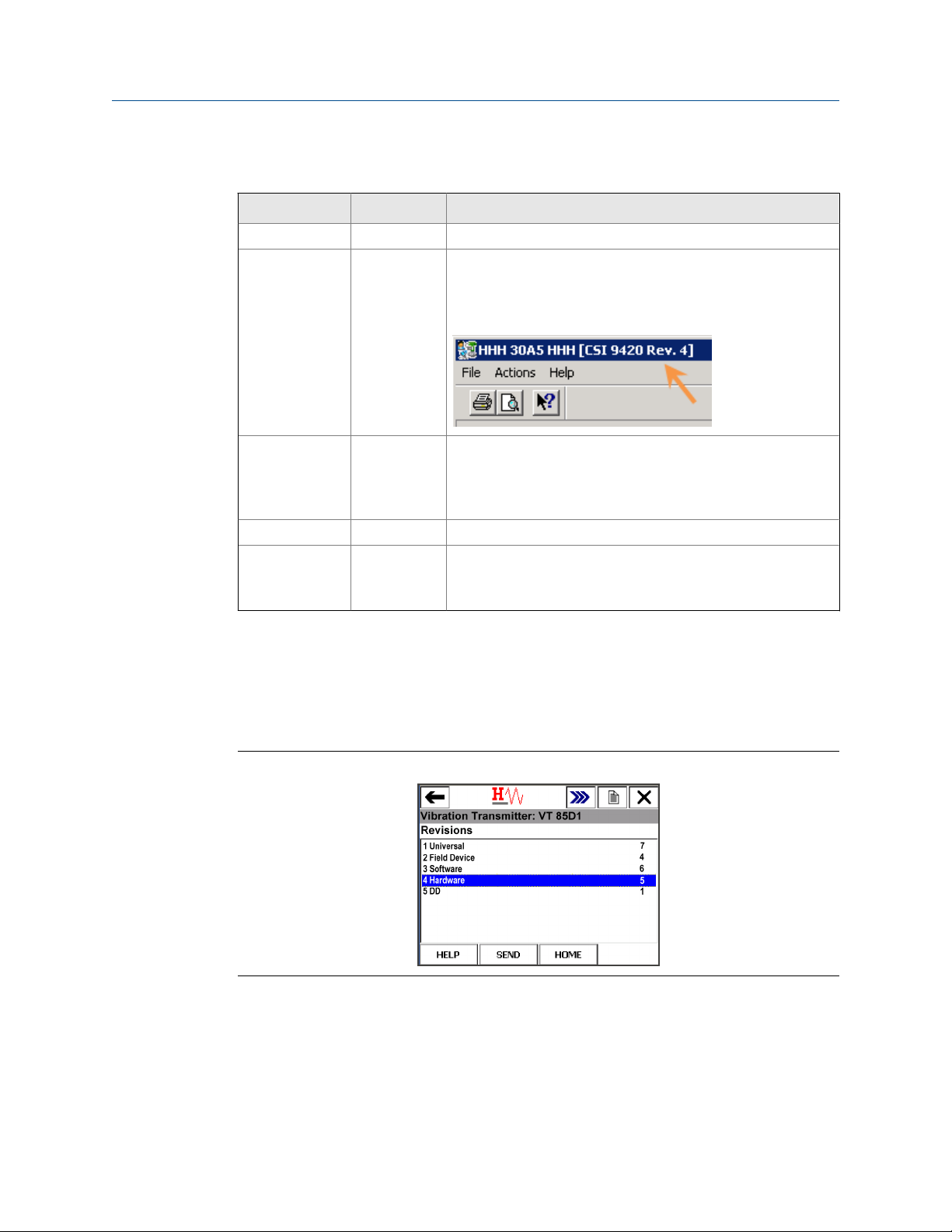
Device revision information
Revision Current level Description
Universal 7 This is the HART version the transmitter supports.
Field device
Software 6 This is the current software version.
Hardware 5 This is the hardware revision.
DD 1 This is the Device Descriptor (DD) revision.
(1)
4 This is the major revision of the transmitter and corresponds
with a major interface release.
When using AMS Device Manager, this revision can be found on
the screen title.
The software may be occasionally modified to refine
functionality. When major functionality is added, the device
revision increases.
The device descriptor is primarily used for configuring devices
in the field.
Introduction
(1) If you have an older device revision, a factory upgrade may be possible in some cases. Contact Product
Support for more information.
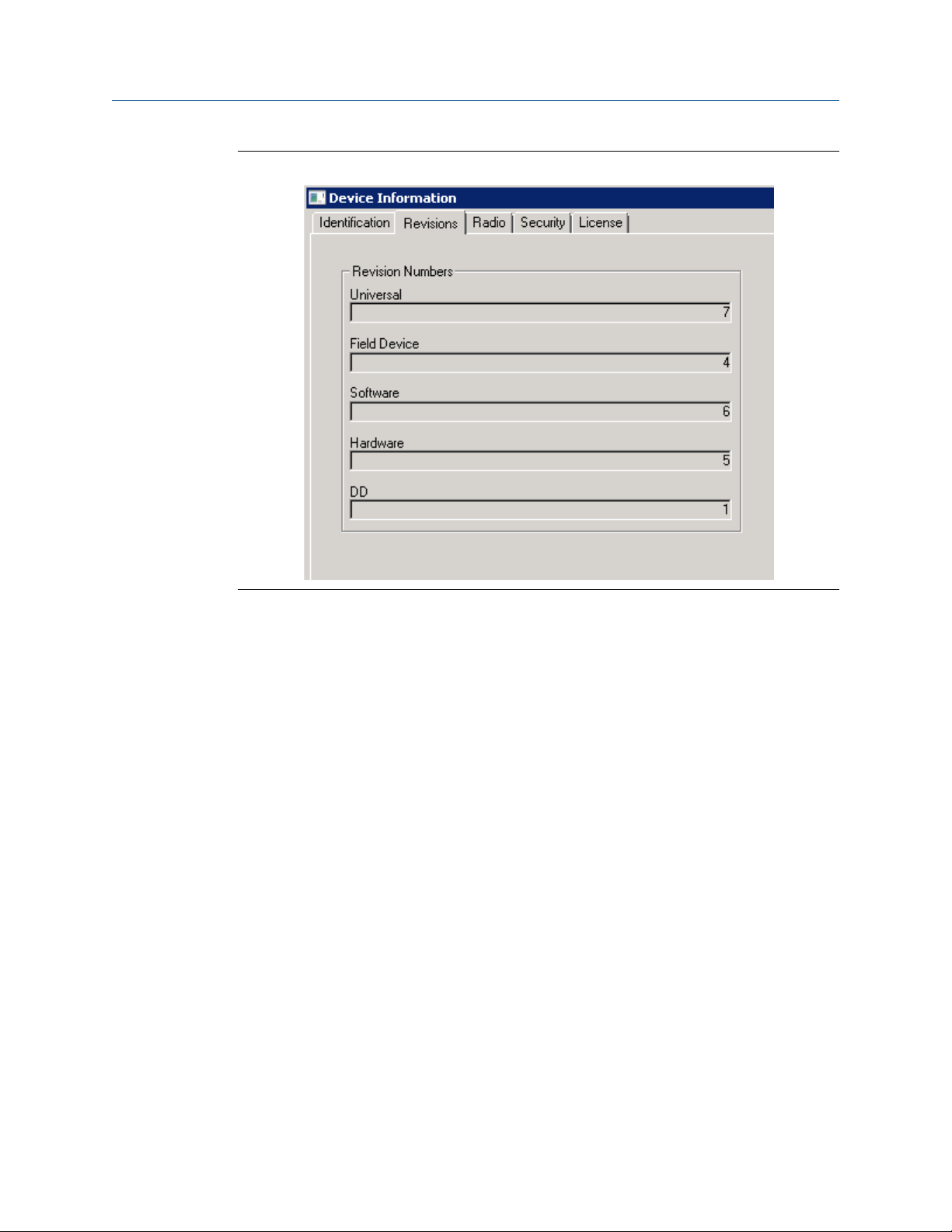
You can view the revision information in a Field Communicator and in AMS Device
Manager.
Revision numbers in a 475 Field CommunicatorFigure 1-1:
MHM-97408, Rev 15 3
Page 10
Introduction
Revision numbers in AMS Device ManagerFigure 1-2:
4 MHM-97408, Rev 15
Page 11

1.3 Considerations
General
Electrical vibration sensors, such as accelerometers, produce low-level signals proportional
to their sensed vibration. With simple HART configuration, the transmitter converts the
low-level sensor signal to a wireless-enabled signal.
Commissioning
The transmitter can be commissioned before or after installation. You can commission it
on the bench before installation to ensure proper operation and to be familiar with its
functions.
Make sure the instruments are installed in accordance with applicable field wiring
practices.
The CSI 9420 device is powered whenever the power module is installed. To avoid
depleting the power module, remove it when the device is not in use.
Installation
Introduction
When choosing an installation location and position, provide ample access to the
transmitter. For best performance, the antenna should be vertical, with some space
between objects in a parallel metal plane such as a pipe or metal framework. Pipes or
framework may adversely affect the performance of the antenna.
Electrical
Smart
Power
Module
The power module contains two “C” size primary lithium/thionyl chloride
batteries. Each power module contains approximately 2.5 grams of lithium,
for a total of 5 grams in each pack. Under normal conditions, the power
module materials are self-contained and are not reactive as long as the
batteries and the power module pack integrity is maintained. Take care to
prevent thermal, electrical, or mechanical damage and protect contacts to
prevent premature discharge.
CAUTION!
Use caution when handling the power module. The power module may be
damaged if dropped from heights in excess of 20 feet.
External
DC line
power
Certain versions of the CSI 9420 are available for connecting to an external
10-28 VDC power source. This is used in place of the power module.
WARNING!
The CSI 9420 may not carry the same hazardous area ratings when operated
with external DC line power.
Sensor Make sensor connections through the cable entry at the side of the
connection head. Provide adequate clearance for cover removal.
MHM-97408, Rev 15 5
Page 12

Introduction
Environmental
The transmitter operates within specifications for ambient temperatures between –40°F
and 185°F (–40°C and 85°C).
Verify that the operating environment of the transmitter is consistent with the appropriate
hazardous location certifications.
1.4 Return of materials
You may need to ship the CSI 9420 to an Emerson Product Service Center for return or
maintenance. Before shipping, contact Emerson Product Support to obtain a Return
Materials Authorization (RMA) number and receive additional instructions.
Emerson Product Support contact information:
Global Service Center (GSC)
Phone: 1-800-833-8314
1-877-812-4036
Email: mhm.custserv@emerson.com
Web: http://www.assetweb.com/mhm and select Product Support
World Wide Customer Service (WWCS)
Phone: 1-888-367-3774 (Option 2 CSI)
Email: wwcs.custserv@emerson.com
Note
If the transmitter has been exposed to hazardous substances, a Material Safety Data Sheet (MSDS)
must be included with the returned materials. An MSDS is required by law to be available to people
exposed to specific hazardous substances.
6 MHM-97408, Rev 15
Page 13

2 Configuration
Topics covered in this chapter:
• Configuration overview
• Configuration with a Field Communicator
• Configuration with AMS Device Manager
• Configuration with AMS Machinery Manager
2.1 Configuration overview
You can configure the CSI 9420 either prior to installation or after the device is installed at
the measurement location. You do not need to physically install or connect to the
transmitter to complete the configuration. The transmitter, however, reports an alert until
the sensor is connected; this is the expected behavior.
Configuration
Note
The specific user interface for performing the configuration varies depending on the host used.
Procedure
1. Connect to a wired HART interface.
Skip this step if your CSI 9420 is purchased pre-configured from the factory.
2. Set the wireless network credentials (Network ID and Join Key) using wired
connection.
Perform this step for the device to join a wireless network. After the device has
joined, you can complete the rest of the steps over a wireless link.
3. (Optional) Name the device (Tag and Device Description).
By default, the tag is VT xxxx, where xxxx is the unique radio ID on the wireless
network. The device joins the network and operates correctly even if no changes are
made, but it is usually preferable to name the device something meaningful for the
specific application.
4. Specify the type of sensor installed (for example: 1 accelerometer, 1
accelerometer with temperature, or 2 accelerometers) and name the sensor.
The factory default configuration is one accelerometer named SENSOR 1. Complete
this step for different configurations and name the sensor something meaningful for
the specific application.
5. Enter the sensor sensitivity.
For improved accuracy, replace the nominal sensitivity value of 25 mV per g (2.55
mV per m/s2) (default) with the value corresponding to your specific sensor.
MHM-97408, Rev 15 7
Page 14

Configuration
6. Specify the units (English, metric, or SI) that will be used for each parameter.
By default, units are set to English, unless the device is shipped to Japan.
7. Specify which measurements (velocity, temperature, etc.) correspond to the
process variables PV, SV, TV, and QV.
By default, PV is the Overall Velocity on sensor 1, SV is the PeakVue measurement on
sensor 1, TV is the sensor 1 bias voltage, and QV is the supply voltage.
8. Specify alert levels.
Determine the thresholds at which measurement alerts will display and determine
the behavior of device alerts.
9. Specify how the parameters will be published (optimized mode or generic
mode).
By default, the device is configured to use generic mode as it provides the most
consistent overall performance.
10. Specify how often the parameters are published (update rate).
The default update rate is once every 60 minutes. A faster update rate is not
recommended, unless the device is powered by an external power source, as it
significantly reduces the power module life.
11. Optimize for power consumption.
Reduce the publish rate and set the LCD mode to Off to minimize power
consumption. As an additional step, you can configure the PowerSave mode
settings to extend the power module life.
12. Configure trending of parameters.
You can trend parameters in multiple locations such as in a plant historian, in AMS
Machinery Manager, and in a DCS control system.
13. If the device configuration will not be managed by a HART DCS (such as DeltaV),
specify whether AMS Machinery Manager can make configuration changes.
By default, the device is set for a DCS to manage the configuration, and changes
from AMS Machinery Manager are not permitted. You can, however, allow AMS
Machinery Manager to make configuration changes by enabling MHM Access
Control from AMS Device Manager or from a Field Communicator.
14. If the device is licensed for the Advanced Diagnostics application (spectral data
retrieval), configure storage of energy bands, spectra, and waveforms in the
AMS Machinery Manager database.
With the Advanced Diagnostics application, you can collect data on-demand,
automatically at periodic intervals, or on alert. Store on Alert is the recommended
operating mode.
8 MHM-97408, Rev 15
Page 15
2.1.1 Connect to a wired HART interface
Unless the CSI 9420 is purchased pre-configured from the factory, you must connect it to a
wired HART interface. This is to define device credentials that allow the device to
communicate on your wireless network. You can also define other device configurations
such as sensor type and alert thresholds at this time.
Notes
• Use the wired HART interface only for configuration. Dynamic variables (such as measured
vibration parameters) are not updated when communicating on the wired interface.
• The CSI 9420 does not communicate simultaneously on both the wired and wireless HART
interfaces. You will lose wireless connectivity when you connect to the wired HART interface.
Configuration changes are not reflected in a wireless host until connection has been reestablished. To avoid loss of synchronization, disconnect hosts relying on the wireless link
when communicating with the device on the wired interface.
For example, if you are viewing a configuration screen in AMS Device Manager through a
wireless link, and you leave this screen open while making changes with a Field
Communicator, you will have to exit AMS Device Manager and then re-open it (or re-scan the
device) after the wireless connection has been restored in order to see the changes.
Configuration
Procedure
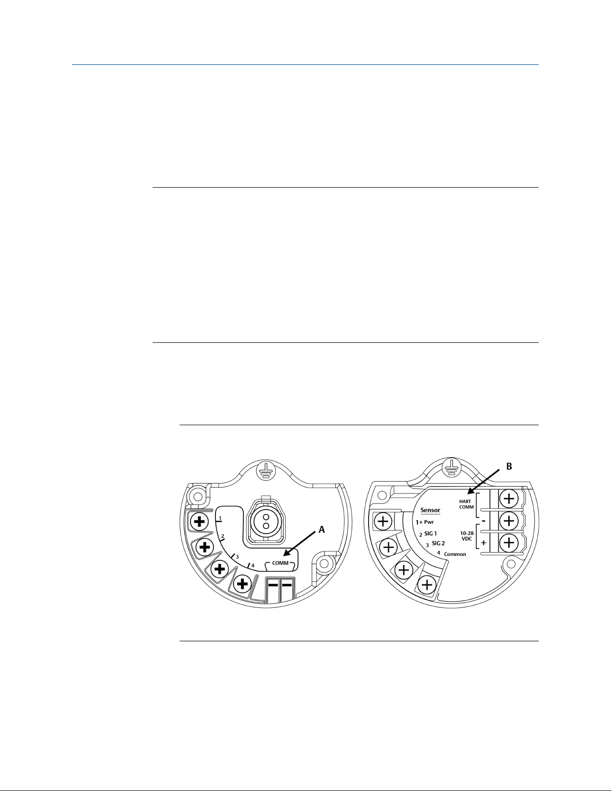
1. Remove the transmitter back cover.
This exposes the terminal block and HART communication terminals.
Figure 2-1:
CSI 9420 terminal block with two-wire, polarity-independent
connection
A. COMM terminals (power module version)
B. HART COMM terminals (externally powered version)
2. Connect the power module or supply power using an external power source.
MHM-97408, Rev 15 9
Page 16
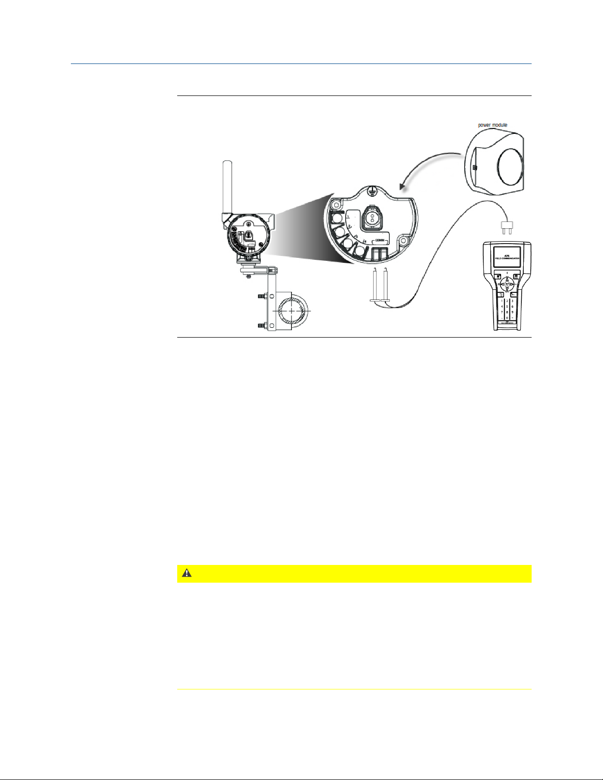
Configuration
Field Communicator and power module connectionFigure 2-2:
3. Configure using a Field Communicator, AMS Device Manager, or any HART-enabled
host.
Press Send to send configuration changes to the transmitter.
The CSI 9420 enters “HART Listen” mode for communication on the wired interface.
HART Listen is displayed on the optional LCD, if it is installed.
If the device is unable to enter the HART Listen mode during its boot sequence or
while performing its real-time vibration measurement, retry the initial wired HART
handshaking sequence.
If repeated attempts to establish wired communication fail, you can force the device
into a HART Listen mode by removing the transmitter front cover and pressing the
CONFIG button once. Once the device enters HART Listen mode, it remains in this
mode until you press the CONFIG button, the power cycles, or no activity is seen on
the wired interface for three minutes. Pressing the CONFIG button a second time
causes the device to exit HART Listen mode.
CAUTION!
The front electronics end cap (the cap covering the LCD) is certified for Class I, Division I
in appropriate gas environments (check the nameplate on the device for details).
Exposing the electronics to a production environment can allow particulates, moisture,
and other airborne chemicals to enter into the device, which could lead to
contamination and potential product performance issues. In all cases, whenever
opening the front end cap, be sure to seal it completely afterwards by tightening until
the black O-ring is no longer visible. For an illustration on how to properly seal the end
cap, see Figure 3-12.
10 MHM-97408, Rev 15
Page 17

4. When configuration is complete over the wired HART interface, disconnect the
transmitter from the communication wires to re-establish wireless communication.
This may take several minutes.
2.1.2 Set the wireless network configuration
This enables the transmitter to communicate with the Smart Wireless Gateway and with
other systems. This is the wireless equivalent of connecting wires from a transmitter to a
control system input.
Procedure
1. From the Smart Wireless Gateway, click Setup > Network > Settings to obtain the
Network ID and Join Key.
2. Using a Field Communicator or AMS Device Manager with a wired modem, enter the
Network ID and Join Key so that they match the Network ID and Join Key from the
Smart Wireless Gateway.
Note
If the Network ID and Join Key are not identical to the gateway settings, the CSI 9420 will not
communicate with the network.
Configuration
MHM-97408, Rev 15 11
Page 18

Configuration
2.1.3 Configuration options
The CSI 9420 configuration options control the following operations:
• How measurement results are reported and how often are they reported
• The number and type of sensors installed
• How and when alerts are generated
Table 2-1 shows the default device configuration. You can change these configurations
from AMS Device Manager or from a Field Communicator.
Default device configurationTable 2-1:
Configuration option Default value
Publishing mode Generic
Update rate 60 minutes
PowerSave mode PowerSave Skip Multiplier of 1X
LCD mode Off
Power source Power module/battery
MHM Access Control Disabled
Write Protect No
Sensor Configuration
Sensor type 1 Accelerometer (sensor 2 not installed)
Sensor sensitivity 25 m V/g
Velocity Fmax 1000 Hz
PeakVue true Fmax 1000 Hz
Velocity spectrum lines of resolution 400 lines
PeakVue spectrum lines of resolution 1600 lines
Units
Variable mappings
PV Overall velocity, sensor 1
SV PeakVue, sensor 1
TV Bias, sensor 1
QV Supply voltage
English
Overall velocity: in/s RMS
PeakVue: g's
Temperature: °C
12 MHM-97408, Rev 15
Page 19

2.1.4 Sensor configuration
The CSI 9420 can be installed with two accelerometers, or with one accelerometer with an
embedded temperature sensor. Table 2-2 shows the possible sensor configurations and
variable mappings.
Possible sensor configurations and variable mappingsTable 2-2:
Configuration
Dynamic process
variables
PV Overall Velocity Sensor 1 Overall Velocity Sensor 1 Overall Velocity Sensor 1
SV PeakVue Sensor 1 PeakVue Sensor 1 PeakVue Sensor 1
TV Bias Sensor 1 Sensor Temperature Overall Velocity Sensor 2
QV Supply Voltage Supply Voltage PeakVue Sensor 2
Unmapped device
variables
Available process variables based on sensor configuration
Sensor 1: Accelerometer
Sensor 2: Not Installed
Ambient Temperature
Sensor 1 and 2: Accelerometer
with Temperature
Ambient Temperature
Bias Sensor 1
Sensor 1: Accelerometer
Sensor 2: Accelerometer
Bias Sensor 1
Bias Sensor 2
Ambient Temperature
Supply Voltage
Each sensor is characterized at the factory to determine the precise sensitivity. This
information is included with the sensor, in the form of a certificate, and may be crossreferenced with the serial number as shown in Figure 2-3.
Calibration certificateFigure 2-3:
MHM-97408, Rev 15 13
Page 20

Configuration
2.1.5 Measurement parameter units
Table 2-3 shows the measurement parameters and available units that can be configured
for each parameter.
Measurement parameter unitsTable 2-3:
Parameter Units
Velocity (Overall 1, Overall 2)
PeakVue maximum value (PeakVue 1, PeakVue 2)
Temperature (Temperature 1, Ambient)
Sensor Bias (Bias 1, Bias 2) V
Supply Voltage V
mm/s RMS
in/s RMS
2
m/s
g’s
°C
°F
2.1.6 Alert levels
The CSI 9420 sets HART status bits to indicate when measured values exceed the
configured thresholds. Each measured value has three levels: Advisory, Maintenance, and
Failed that can be set independently. These thresholds are pre-configured at the factory to
reasonable generic values for single-stage, electric motor-driven equipment trains
operating at 1200–3600 RPM.
The level at which these thresholds should be set depends on the type of equipment being
monitored and on your specific process.
One rule of thumb for vibration is to examine the current level at which the equipment is
operating. Assuming the equipment is in good working condition, set the Advisory level at
2x the current value (or at a minimum of 0.05 in/s RMS, whichever is greater), set the
Maintenance level at 4x the current value, and set the Failed level at 8x the current value.
For example, if the current value for Overall Velocity is 0.1 in/s, set the Advisory threshold
at 0.2 in/s, the Maintenance threshold at 0.4 in/s and the Failed threshold at 0.8 in/s. While
this type of vibration program is not recommended, it can provide a starting point when
no other information is available.
Default alert thresholds for vibrationTable 2-4:
Advise Maintenance Failed
Alert limits
Overall velocity
(sensor 1, 2)
PeakVue
(sensor 1, 2)
Default value
0.14 in/sec
3.556 mm/s
6 g's
58.8399 m/s
2
Report
notification
Yes
Yes
Default value
0.35 in/sec
8.89 mm/s
10 g's
98.0665 m/s
notification
2
Report
Yes
Yes
Default value
1 in/sec
25.4 mm/s
15 g's
147.09975 m/s
notification
2
Report
Yes
Yes
14 MHM-97408, Rev 15
Page 21

Configuration
Default alert thresholds for vibration (continued)Table 2-4:
Advise Maintenance Failed
Alert limits
Sensor
temperature
Bias
(sensor 1, 2)
Ambient
temperature
Supply voltage <6.0 V No <5.7 V Yes <5.3 V* Yes
*These are read-only parameters and cannot be modified.
Default value
65°C
149°F
– – – –
– – – –
Report
notification
Yes
Default value
75°C
167°F
Report
notification
Yes
Default value
85°C
185°F
Above: >3V
Below: <2V
Above: 85°C
(185°F)*
Below: -40°C
(-40°F)*
Report
notification
Yes
Yes*
Yes*
A good rule of thumb for establishing the PeakVue alert levels is to use the rule of 10's. This
applies for most rolling element bearing equipment with a turning speed between 900 and
4000 CPM. Using this approach, the Advisory alert would be set at 10 g's, the Maintenance
alert at 20 g's, and the Failed alert at 40 g's. In general, PeakVue alert levels can then be
interpreted as follows:
10 g's Indication of Abnormal Situation
20 g's Serious Abnormal Situation - Maintenance Plan Required
40 g's Critical Abnormal Situation - Implement Maintenance Plan
For more information on PeakVue, see Section 5.2.
The default alert thresholds for temperature correspond closely to a generic open dripproof (ODP) motor with class F insulation and a service factor of 1.15, operating at an
ambient temperature of 40°C or below and at an altitude of 1000 meters or below . These
values are also reasonable thresholds to use when there is no knowledge of the process,
the type of machinery, or the operating environment. For more information, see Chapter 5.
Default alert thresholds for temperatureTable 2-5:
Parameter
Temperature
Advisory Maintenance Failed
Level Enabled Level Enabled Level Enabled
149°F
(65°C)
Yes
167°F
(75°C)
Yes
185°F
(85°C)
Yes
The configurable device alerts include accelerometer bias and supply voltage. The default
settings for these alerts are shown in Table 2-6.
MHM-97408, Rev 15 15
Page 22

Configuration
Default levels for configurable device alerts Table 2-6:
Parameter
Accelerometer
Bias
Supply Voltage < 6.0 V No < 5.7 V Yes < 5.3 V Yes
Notes
• The supply voltage measurement is made under load conditions. The supply voltage may
read differently with the CSI 9420 versus other Emerson transmitters or multimeters.
• Prior to sensor connection, it is normal to see alerts related to bias failure. These alerts go
away when the sensor is installed correctly.
• When any measured process parameter (Velocity, PeakVue, or Temperature) exceeds the
configured Advisory, Maintenance, or Failed threshold, this causes an “Advisory” indication
that you can view from AMS Device Manager (or in another graphical host). This indicator
itself does not set a status bit.
Advisory Maintenance Failed
Level Enabled Level Enabled Level Enabled
N/A N/A N/A N/A < 2 V or > 3 V Yes
2.1.7 Publishing mode
The CSI 9420 can publish in either of two modes: optimized or generic (default).
Optimized mode uses less power by combining a large amount of information into a single
command. In this mode, only the four standard process variables (PV, SV, TV, and QV) are
published at the specified update interval and cached in the Smart Wireless Gateway.
When values are cached in the gateway, it is not necessary to wake the device for the host
system to be able to read the variables. The other variables are still available, but any
request to read one of them wakes the device and consumes power.
Generic mode publishes all the process variables the device can produce. This mode
requires three publish messages, which requires approximately 5% more power.
If you are only trending measurements mapped to PV, SV, TV, and QV, use optimized
mode. If you are trending additional variables, use generic mode.
2.1.8 Update rate
The default update rate is 60 minutes. This is the maximum (fastest) recommended
update rate. You can change this at commissioning or at any time through AMS Device
Manager, a Field Communicator, or the Smart Wireless gateway web server. You can set
the update rate from 1 minute to 1 hour.
Note
If the device uses a power module, and is configured to publish at the fastest allowable update rate
(once per minute), the power module is expected to last only about 2-3 months.
For faster update rates, if your application allows it, use an external DC power option.
16 MHM-97408, Rev 15
Page 23

2.1.9 Minimize power consumption
The primary way to minimize power consumption is to reduce the publish rate.
Two other configuration settings that affect power consumption are:
• LCD (Liquid Crystal Display)
• PowerSave mode
LCD
Disable the LCD after installation is complete if it is not required during normal operation.
It is neither necessary nor sufficient to physically remove the LCD; it must be disabled
through configuration in order to save power. From AMS Device Manager, select the
wireless network where the transmitter is connected, right-click the transmitter and select
Configure > Manual Setup > General Settings tab > LCD Mode > Off.
Note
Disabling the LCD (not removing it, just disabling it) through configuration provides power savings of
about 15–20%.
Configuration
Leave the LCD installed even if it is disabled to provide valuable diagnostic information. To
view the LCD, remove the front cover and press the DIAG button. This wakes the device and
displays current information. This can be beneficial for taking a quick reading and to aid in
troubleshooting.
CAUTION!
The front electronics end cap (the cap covering the LCD) is certified for Class I, Division I in
appropriate gas environments (check the nameplate on the device for details).
Exposing the electronics to a production environment can allow particulates, moisture, and
other airborne chemicals to enter into the device, which could lead to contamination and
potential product performance issues. In all cases, whenever opening the front end cap, be
sure to seal it completely afterwards by tightening until the black O-ring is no longer visible.
For an illustration on how to properly seal the end cap, see Figure 3-12.
PowerSave mode
PowerSave mode is available in CSI 9420 devices that are Rev. 3 or later and it enables the
device to make measurements less frequently, thereby conserving power. This is ideal
when either power module life is more critical than the acquisition rate or when changes in
vibration are only expected to occur over extended periods of time.
You can configure the settings for the PowerSave mode in AMS Machinery Manager (MHM
Access Control must first be enabled) and in AMS Device Manager. The specific field is
referred to as PowerSave Skip Multiplier. It is the number of times the transmitter skips
data acquisitions between updates to the gateway.
At any point, the effective acquisition rate for the CSI 9420 is defined as:
Effective Acquisition Rate = (Update Rate) x (PowerSave Skip Multiplier)
MHM-97408, Rev 15 17
Page 24

Configuration
Valid settings for the PowerSave Skip Multiplier range from 1X to 24X. In order to extend
power module life, it should only be combined with a long update rate such as 60 minutes
(54 minutes may be optimal for older versions of the CSI 9420). When this value is set to
1X, the CSI 9420 acquires a new reading at the update rate. A PowerSave Skip Multiplier of
2X combined with a 60-minute update rate results in a new acquisition every 120 minutes
(every two hours). Similarly, a PowerSave Skip Multiplier of 24X with a 60-minute update
rate results in a new acquisition every 1440 minutes (once per day).
2.1.10 Trend parameters
You can trend parameters in multiple locations such as in a plant historian or in AMS
Machinery Manager. The method for configuring this functionality is contained in the
associated software and the details of all the possibilities are beyond the scope of this
manual. This manual only indicates some of the general capabilities and version
requirements.
You can trend values in essentially any host that accepts Modbus or OPC inputs. Configure
OPC tags and Modbus registers for wireless devices in the Smart Wireless Gateway web
interface. Refer to the Smart Wireless Gateway User Manual for additional information.
The settings in the gateway and the host must be consistent and entered in both locations
(for example, Modbus register definitions).
DeltaV integrates native wireless I/O devices on the control network. Refer to the DeltaV
documentation for more information on the required version. You can manage wireless
devices as native HART devices, and trend variables accordingly. This type of installation
also allows richer alerting and diagnostics because the full HART capabilities are available.
Ovation 3.3 or later also integrates the Smart Wireless Gateway with all the associated
benefits of HART.
AMS Machinery Manager 5.4 or later supports HART functionality to read configuration
and alert information, as well as the dynamic parameters from the CSI 9420. This allows
AMS Machinery Manager to auto-discover all of the devices on the wireless mesh as well as
the specific sensor configurations, units settings, and variable mappings for CSI 9420
devices.
Also, with AMS Machinery Manager and CSI 9420 devices (that are licensed for the
Advanced Diagnostics application), you can trend Energy Band parameters. For more
information, see Section 2.4.1.
DeltaV versions prior to 10.3 and Ovation versions prior to 3.3, though not integrated
through HART, accept Modbus values from the wireless devices. DeltaV also accepts OPC
values.
18 MHM-97408, Rev 15
Page 25

2.1.11 Remove the power module
The CSI 9420 device is powered whenever the power module is installed. To avoid
depleting the power module, remove it when the device is not in use.
After you have configured the sensors and network, disconnect the communication leads,
remove the power module (if the device is not already installed), and replace the
transmitter cover. You should insert the power module only when you are ready to
commission the device.
2.2 Configuration with a Field Communicator
You can configure the CSI 9420 using a Field Communicator. Follow the connection
diagram in Figure 2-2.
A Rev 4 DD is recommended when using a Field Communicator to configure the CSI 9420.
The DD for the CSI 9420 is located on the DVD that came with the transmitter. Refer to the
Field Communicator User’s Manual for more details on DDs or go to http://
www2.emersonprocess.com/en-us/brands/Field-Communicator/Pages/SysSoftDDs.aspx
for instructions on adding a DD for CSI 9420.
Configuration
The CSI 9420 requires Field Communicator System Software version 3.2 or later.
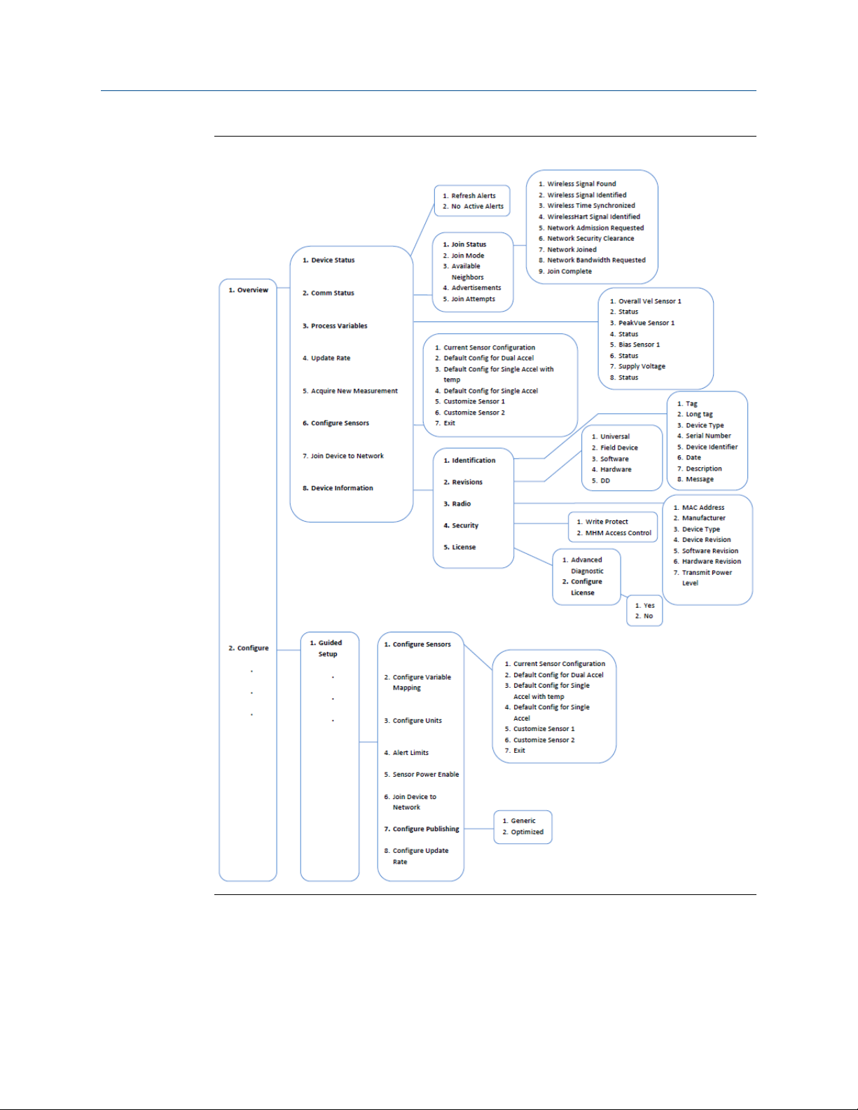
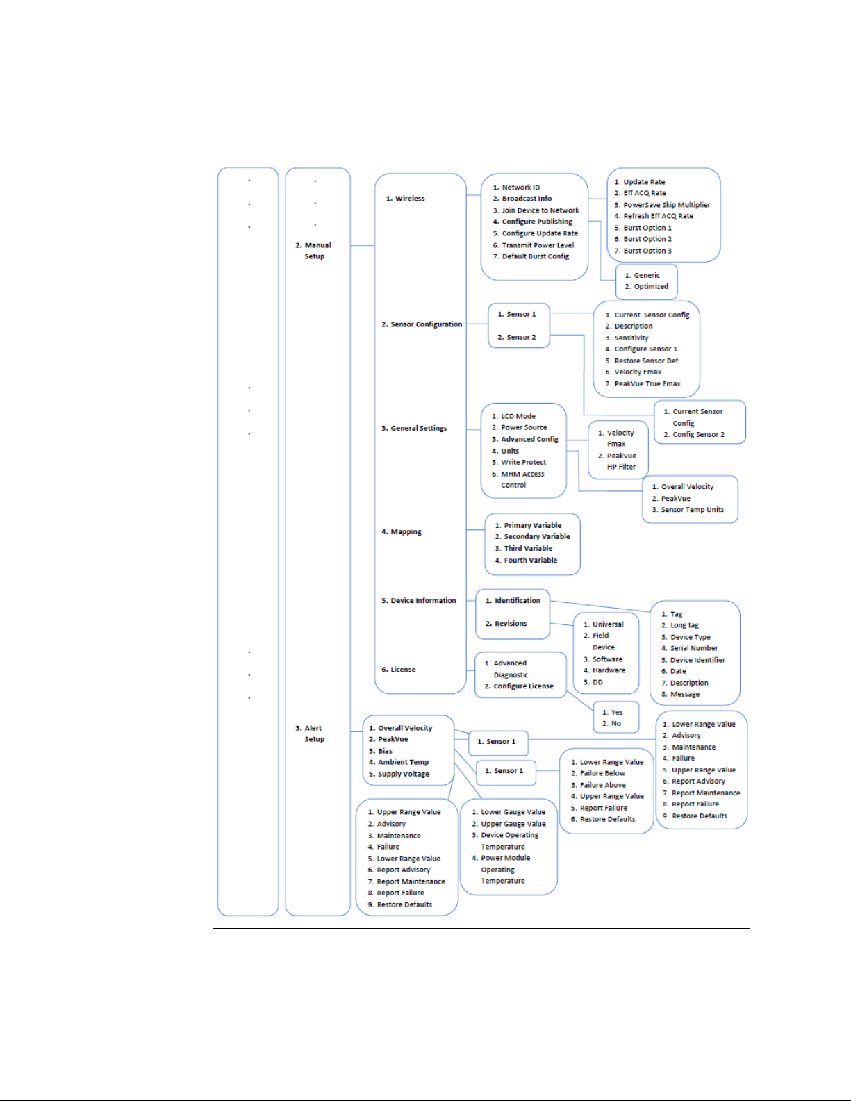
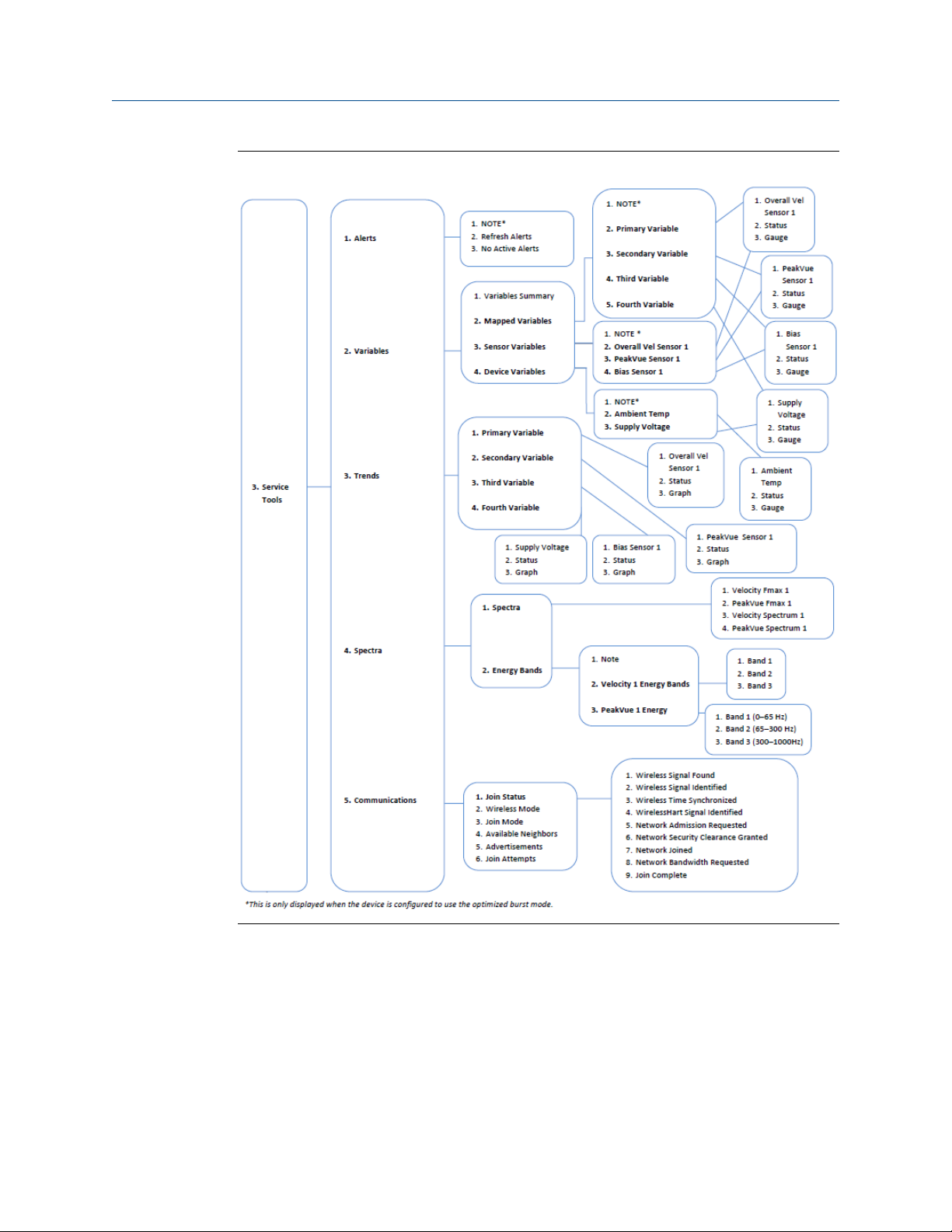
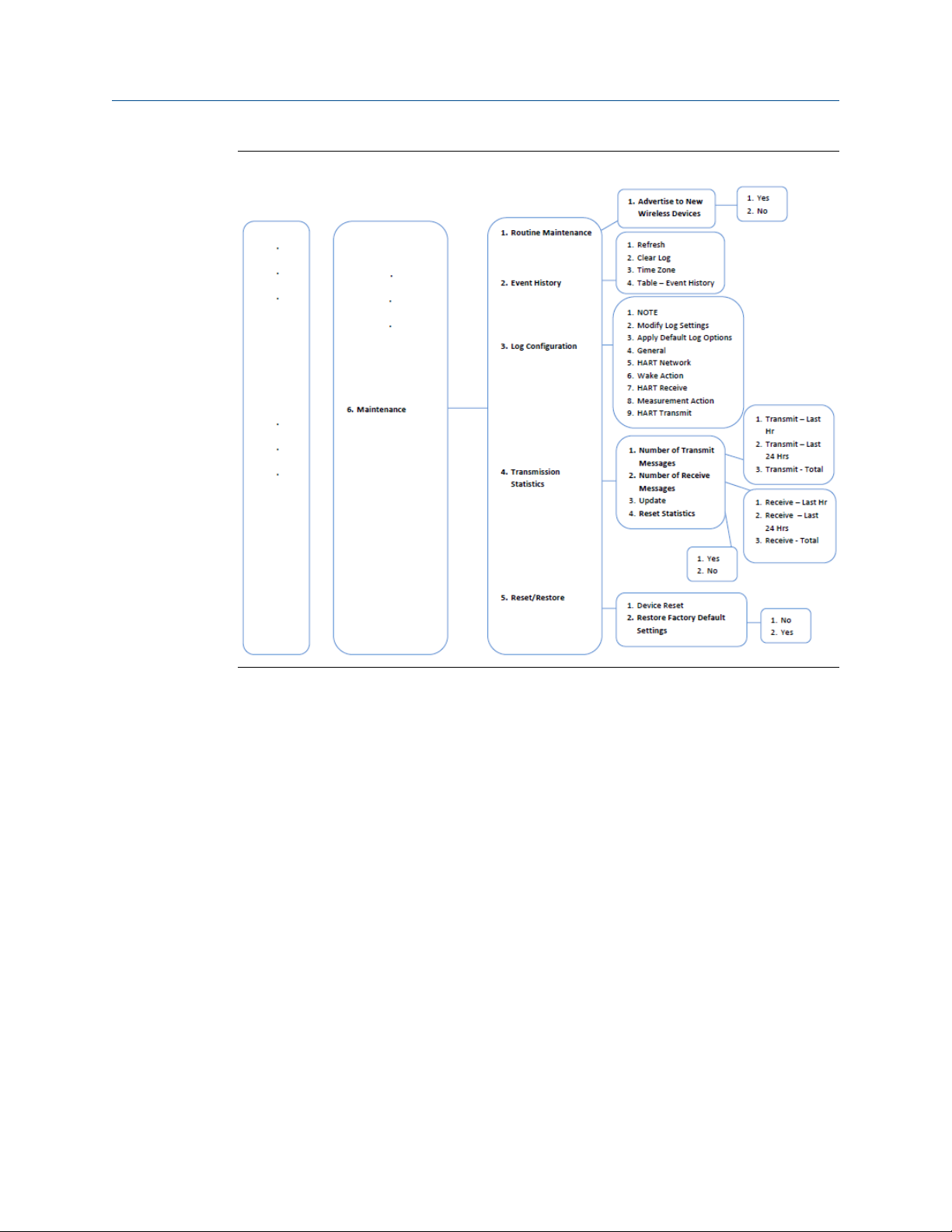
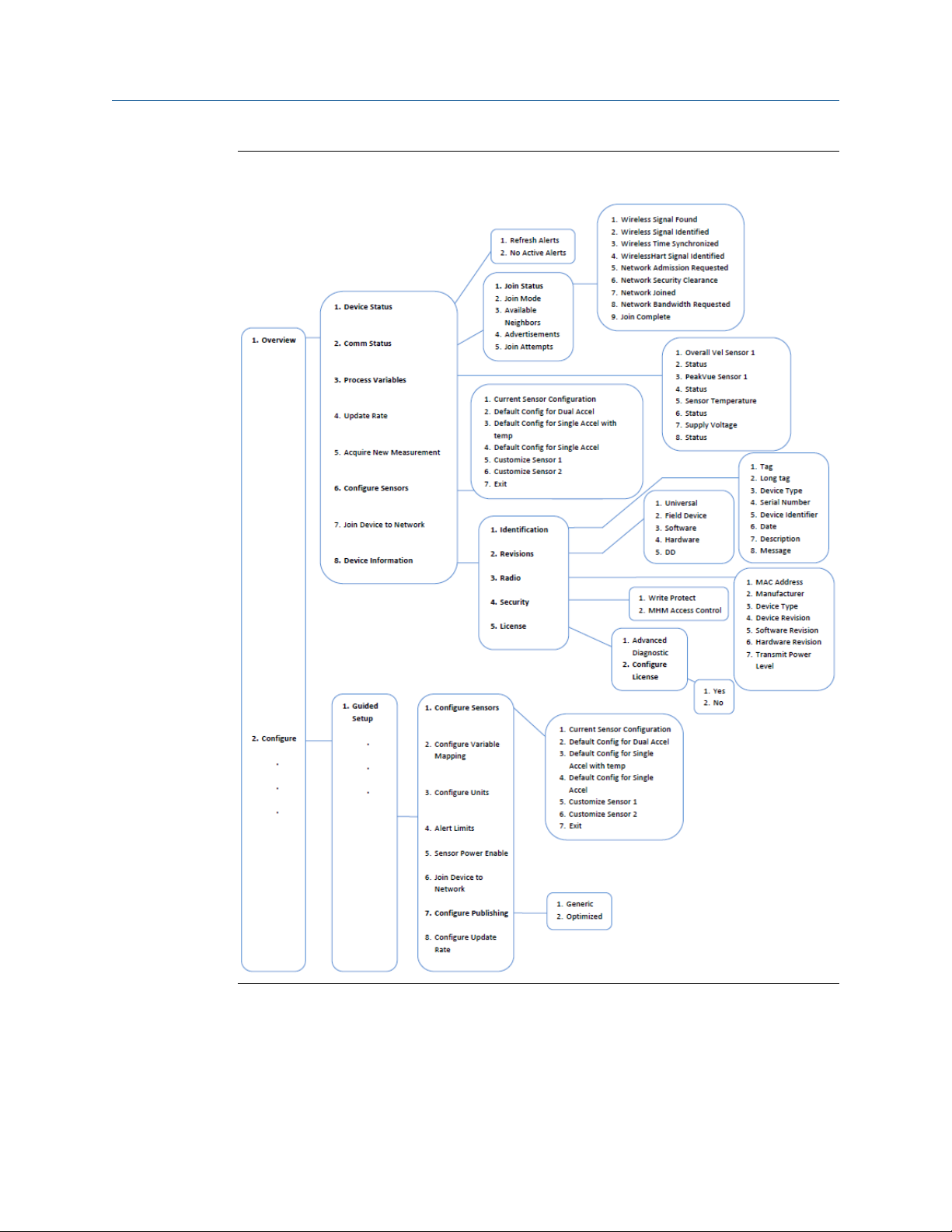
Figure 2-4 through Figure 2-15 show the Field Communicator configuration menu trees for
CSI 9420 using a Rev 4 DD. For ease of operation, you can access some common tasks in
several locations of the menu structure.
MHM-97408, Rev 15 19
Page 26
Configuration
Field Communicator menu tree for CSI 9420, one accelerometer: 1 of 4Figure 2-4:
20 MHM-97408, Rev 15
Page 27
Configuration
Field Communicator menu tree for CSI 9420, one accelerometer: 2 of 4Figure 2-5:
MHM-97408, Rev 15 21
Page 28
Configuration
Field Communicator menu tree for CSI 9420, one accelerometer: 3 of 4Figure 2-6:
22 MHM-97408, Rev 15
Page 29
Configuration
Field Communicator menu tree for CSI 9420, one accelerometer: 4 of 4Figure 2-7:
MHM-97408, Rev 15 23
Page 30
Configuration
Figure 2-8:
Field Communicator menu tree for CSI 9420, one accelerometer with
temperature: 1 of 4
24 MHM-97408, Rev 15
Page 31

Configuration
Figure 2-9:
Field Communicator menu tree for CSI 9420, one accelerometer with
temperature: 2 of 4
MHM-97408, Rev 15 25
Page 32

Configuration
Figure 2-10:
Field Communicator menu tree for CSI 9420, one accelerometer with
temperature: 3 of 4
26 MHM-97408, Rev 15
Page 33

Configuration
Figure 2-11:
Field Communicator menu tree for CSI 9420, one accelerometer with
temperature: 4 of 4
MHM-97408, Rev 15 27
Page 34

Configuration
Field Communicator menu tree for CSI 9420, two accelerometers: 1 of 4Figure 2-12:
28 MHM-97408, Rev 15
Page 35

Configuration
Field Communicator menu tree for CSI 9420, two accelerometers: 2 of 4Figure 2-13:
MHM-97408, Rev 15 29
Page 36

Configuration
Field Communicator menu tree for CSI 9420, two accelerometers: 3 of 4Figure 2-14:
30 MHM-97408, Rev 15
Page 37

Configuration
Field Communicator menu tree for CSI 9420, two accelerometers: 4 of 4Figure 2-15:
MHM-97408, Rev 15 31
Page 38

Configuration
2.2.1 Field Communicator fast key sequences
The following fast key sequences assume that you are using a Rev 4 DD. Press Send to save
the changes to the device.
CSI 9420 network configurationTable 2-7:
Key sequence Menu items
Network ID
Broadcast Info
2, 2, 1
(Manual Setup)
2, 1
(Guided Setup)
Join Device to Network
Configure Publishing
Configure Update Rate
Transmit Power Level
Default Burst Config
Configure Sensors
Configure Variable Mapping
Configure Units
Alert Limits
Sensor Power Enable
Join Device to Network
Configure Publishing
Configure Update Rate
CSI 9420 common fast key sequencesTable 2-8:
Function Key sequence Menu items
LCD Mode
Power Source
General settings 2, 2, 3 (Manual Setup)
Alert setup 2, 3
Update rate
Publishing mode
Write protect 2, 2, 3, 5 (Manual Setup) Write Protect
2, 1, 8 (Guided Setup)
2, 2, 1, 5 (Manual Setup)
2, 1, 7 (Guided Setup)
2, 2, 1, 4 (Manual Setup)
Advanced Config
Units
Write Protect
MHM Access Control
Overall Velocity
PeakVue
Bias
Ambient Temperature
Supply Voltage
Configure Update Rate
Configure Publishing
32 MHM-97408, Rev 15
Page 39

Configuration
CSI 9420 common fast key sequences (continued)Table 2-8:
Function Key sequence Menu items
Power options 2, 2, 3, 2 (Manual Setup) Power Source
MHM Access Control 2, 2, 3, 6 (Manual Setup) MHM Access Control
Supply power to sensor 2, 1, 5 (Guided Setup) Sensor Power Enable
Configure variable mapping 2, 1, 2 (Guided Setup) Configure Variable Mapping
Device reset 3, 6, 5
Device Reset
Restore Factory Default Settings
MHM-97408, Rev 15 33
Page 40

Configuration
2.3 Configuration with AMS Device Manager
2.3.1 Configure wireless network credentials in AMS Device Manager
Prerequisites
Before performing operations in AMS Device Manager, first scan the CSI 9420 with a wired
HART modem. Right-click the HART Modem icon in Device Explorer and select Scan All
Devices.
Note
Configuring the wireless network is only applicable using a wired HART modem and cannot be done
using WirelessHART devices.
Procedure
1. Right-click the CSI 9420 device and select Methods > Join Network.
2. Enter the network ID for the wireless network in the Join Device to Network screen
and click Next.
You can obtain the network ID from the Smart Wireless Gateway web server. Click
Setup > Network > Settings.
3. Enter the Join Key in the screens that follow, and click Next.
4. Select the Accept new join key option, and click Next.
5. Click Finish when done.
34 MHM-97408, Rev 15
Page 41

2.3.2 Right-click menu
The right-click menu of the CSI 9420 device in AMS Device Manager provides a quick link
to the Configure, Compare, Service Tools, and Overview windows, as well as to other
context menus available for the device. This document only discusses the Overview,
Configure, and Service Tools windows; for more information on the other context menus,
refer to AMS Device Manager Books Online.
In the Device Explorer view, select the wireless network where the transmitter is
connected and right-click the transmitter to display the context menus.
CSI 9420 right-click menuFigure 2-16:
Configuration
MHM-97408, Rev 15 35
Page 42

Configuration
Overview
Overview windowFigure 2-17:
The Overview window provides a glimpse of the status of the CSI 9420, including the
primary purpose variables associated with it.
You can also access the following shortcuts from this page:
• Device Information
• Configure Sensors
• Join Device to Network
• Acquire New Measurement
36 MHM-97408, Rev 15
Page 43

Configuration
Device Information
From the Overview window, click Device Information to display relevant device information.
Device Information windowFigure 2-18:
Click the Identification tab to display the device tag, long tag, device type, serial number,
identifier, and description.
Click the Revisions tab to display the universal, field device, software, hardware, and DD
revision numbers.
Click the Radio tab to display the device MAC address, manufacturer, device type, revision
numbers, and transmit power level.
Click the Security tab to display Write Protect information and to view whether MHM Access
Control is enabled.
Click the License tab to display installed licensable features such as the Advanced
Diagnostics application.
Click License tab > Configure License to configure/change installed licenses.
MHM-97408, Rev 15 37
Page 44

Configuration
Configure Sensors
From the Overview window, click Configure Sensors to display installed sensors and current
sensor configurations.
Sensor Configuration windowFigure 2-19:
Click the Select Sensor Configuration drop-down to select a sensor configuration to apply to
the installed sensors.
38 MHM-97408, Rev 15
Page 45

Configuration
Join Device to Network
From the Overview window, click Join Device to Network to enter network identifiers and join
keys that will enable the transmitter to join a wireless network.
Join Device to Network windowFigure 2-20:
MHM-97408, Rev 15 39
Page 46

Configuration
Acquire New Measurement
From the Overview window, click Acquire New Measurement to display measurement
statistics for Velocity, PeakVue, bias, and sensor temperature for installed sensors. This
also displays supply voltage and ambient temperature information for the transmitter.
Measurement Statistics windowFigure 2-21:
40 MHM-97408, Rev 15
Page 47

Configure
Configuration
Configure windowFigure 2-22:
The Configure window lets you configure device settings.
Important
To be able to edit configuration settings, select Current in the Time drop-down menu at the bottom of
the screen.
Guided Setup
Guided Setup lets you configure device settings in a guided step-by-step process.
Click Configure Sensors to display or configure installed sensors.
Click Configure Variable Mapping to display or specify which measurements are reported as
the Primary, Secondary, Third, and Fourth variables.
Click Configure Units to configure units for Overall Velocity, PeakVue, and temperature.
Click Alert Limits to define the lower range and upper range values and alert limits for
Advisory, Maintenance, and Failure for each of the process variables. You can also
configure alert reporting from here.
Click Sensor Power Enable to supply power to the sensor for a specific amount of time.
MHM-97408, Rev 15 41
Page 48

Configuration
Note
Sensor Power Enable is only available when the device is connected to AMS Device Manager using a
USB or serial HART modem and when the device is connected to a Field Communicator. This feature
is not available when the device is connected to AMS Device Manager using a WirelessHART
connection.
Click Join Device to Network to enter network identifiers and join keys that will enable the
transmitter to join a wireless network.
Click Configure Publishing to set how parameters are published (generic or optimized).
Click Configure Update Rate to set how often the device acquires and reports new
measurements (update rate) and to specify the number of times the transmitter skips data
acquisitions between updates to the gateway (PowerSave Skip Multiplier).
Manual Setup
Manual Setup lets you configure device settings manually.
Click the Wireless tab to display wireless network information for the transmitter.
Wireless tabFigure 2-23:
Click Join Device to Network to enter network identifiers and join keys that will enable the
transmitter to join a wireless network.
Click Configure Publishing to set how parameters are published (generic or optimized).
42 MHM-97408, Rev 15
Page 49

Configuration
Click Configure Update Rate to set how often the device acquires and reports new
measurements (update rate) and to specify the number of times the transmitter skips data
acquisitions between updates to the gateway (PowerSave Skip Multiplier).
Click Default Burst Configuration to reset the burst configuration to default values.
Click Refresh Effective Acquisition Rate to refresh the value in the Effective Acquisition Rate
field.
Click the Sensor tab to display current sensor configurations. You can also edit the sensor
sensitivity value from this page.
Sensor tabFigure 2-24:
Click Configure Sensor x to configure the parameters for the specific sensor.
Click Restore Sensor Default to reset the sensor parameters to default values.
MHM-97408, Rev 15 43
Page 50

Configuration
Click the General Settings tab to display or edit general transmitter settings.
General Settings tabFigure 2-25:
Click the LCD Mode drop-down to enable or disable the LCD, or to set it to troubleshooting
mode.
Click the Power Source drop-down to select the transmitter power source.
Select the units for measurement variables from the Overall Velocity, PeakVue, and
Temperature drop-down menus.
Click the MHM Access Control drop-down to enable or disable Access Control for AMS
Machinery Manager. Access Control allows AMS Machinery Manager to make changes to
the CSI 9420 configuration.
CAUTION!
If the device will be commissioned in a HART DCS host (e.g., DeltaV or Ovation), do not enable
AMS Machinery Manager to make changes to the configuration.
Click the Write Protect drop-down to specify whether variables can be written to the device.
44 MHM-97408, Rev 15
Page 51

Click the Mapping tab to specify which measurements are reported as the Primary,
Secondary, Third, and Fourth variables.
Mapping tabFigure 2-26:
Configuration
MHM-97408, Rev 15 45
Page 52

Configuration
Click the Device Information tab to display the device tag, long tag, device type, serial number,
device identifier, and description, and to display the universal, field device, software,
hardware, and DD revision numbers.
Device Information tabFigure 2-27:
46 MHM-97408, Rev 15
Page 53
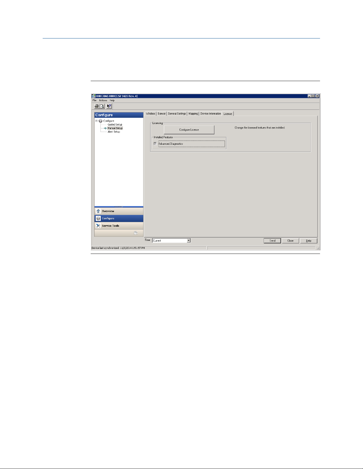
Click the License tab to display installed licensable features such as the Advanced
Diagnostics application.
License tabFigure 2-28:
Configuration
Click Configure License to configure/change installed licenses.
MHM-97408, Rev 15 47
Page 54

Configuration
Alert Setup
Alert Setup lets you configure the upper and lower range values and alarm limits for
Overall Velocity, PeakVue, Bias, Sensor Temperature, Ambient Temperature, and Supply
Voltage.
Alert SetupFigure 2-29:
Click the corresponding sensor/device variable tab and select the Report Advisory, Report
Maintenance, or Report Failure check boxes to generate alarms when actual measured values
exceed the thresholds specified. When these check boxes are not selected, no alarm is
reported.
Click Restore Defaults to restore default alarm thresholds for the selected variable.
48 MHM-97408, Rev 15
Page 55

Service Tools
Service Tools windowFigure 2-30:
Configuration
The Service Tools window displays alert conditions. These include hardware and software
malfunctions or parameters with values beyond specifications.
Alerts
Click Alerts to display active alerts for the device.
MHM-97408, Rev 15 49
Page 56

Configuration
Variables
Click Variables to display graphical gauges of sensor and device variables.
VariablesFigure 2-31:
Click the Mapped Variables tab to display graphical gauges of variables and their mappings.
Click the Sensor Variables tab to display graphical gauges of the variables for each connected
sensor.
Click the Device Variables tab to display graphical gauges of ambient temperature and supply
voltage variables.
50 MHM-97408, Rev 15
Page 57

Configuration
Trends
Click Trends to display hour-long trends for each of the four measurement variables (PV, SV,
TV, and QV).
TrendsFigure 2-32:
Note
The trend plots begin when Trends is selected, and continue to build as long as this remains selected.
MHM-97408, Rev 15 51
Page 58

Configuration
Spectra
Click Spectra to display spectral and analysis parameter data and to configure spectral data
acquisition settings. You can import spectral data to AMS Machinery Manager for further
analysis.
Note
You must have the Advanced Diagnostics application license to view this feature. For more
information on the Advanced Diagnostics application, see Section 2.4.1.
SpectraFigure 2-33:
The Fmax settings define the default frequency range of the thumbnail spectra for Velocity
and PeakVue. If you enable the Average Velocity option in AMS Machinery Manager, you
can configure the high-resolution Velocity Analytical spectrum to return 400 or 800 lines
of resolution, with averaging. If the Average Velocity option is not enabled in AMS
Machinery Manager, the spectrum is calculated at 1600 lines of resolution, with no
averaging.
When vibration data is acquired, a PeakVue waveform is sampled for 3.2 seconds. If you
set the PeakVue True Fmax to 1000 Hz, the first 1.6 seconds of the PeakVue waveform is
used for the analytical spectrum. If you set the Fmax to 500 Hz, the entire 3.2 second
PeakVue waveform is used to calculate the analytical spectrum. Regardless of what you
choose in Fmax, the overall PeakVue trend parameter is calculated over the entire 3.2
second waveform.
52 MHM-97408, Rev 15
Page 59

Configuration
Click Velocity Spectrum x and PeakVue Spectrum x to display spectral plots of the latest
acquired data for Velocity and PeakVue for connected sensors.
Velocity spectrumFigure 2-34:
MHM-97408, Rev 15 53
Page 60

Configuration
PeakVue spectrumFigure 2-35:
54 MHM-97408, Rev 15
Page 61

Click the Energy Bands tab to display calculated energy band values.
Energy Bands tabFigure 2-36:
Configuration
MHM-97408, Rev 15 55
Page 62

Configuration
Communications
Click Communications to display network join status information.
CommunicationsFigure 2-37:
Click the Join Mode drop-down to select when the transmitter attempts to join a network.
56 MHM-97408, Rev 15
Page 63

Maintenance
Click Maintenance to manage the device maintenance and log settings.
MaintenanceFigure 2-38:
Configuration
Click Routine Maintenance tab > Advertise to New Wireless Devices to enable the gateway to
search for new wireless devices on the network. This helps new devices join the network
faster.
Click the Event History tab to display transmitter events such as measurements, HART
transmissions, and wake actions.
Click the Log Configuration tab to configure event logging options. Data from event logs are
useful during a debug process.
Click the Transmission Statistics tab to display statistics related to radio transmission
operation such as communication interval between data requests.
Click the Reset/Restore tab to reset the device or to restore factory default settings.
MHM-97408, Rev 15 57
Page 64

Configuration
2.4 Configuration with AMS Machinery Manager
AMS Machinery Manager can change the data acquisition settings for CSI 9420 devices. If
the device is not commissioned in a HART DCS host (DeltaV or Ovation), you can allow
AMS Machinery Manager to configure settings to provide easier access. You need to
configure MHM Access Control in AMS Device Manager or in a Field Communicator to
allow AMS Machinery Manager to make configuration changes to the CSI 9420.
If the device is commissioned in a HART DCS host, manage the configuration completely
within the DCS. The DCS will generate an alert if you change the configuration externally.
For more details on how to change the configuration from AMS Machinery Manager, refer
to the Data Import topics in AMS Machinery Manager Help.
For device configurations managed by the DCS, you can still set independent alerts in AMS
Machinery Manager to allow you to get a notification without going to the DCS operator
(for example, you can set an alert at a lower threshold within AMS Machinery Manager).
If the primary HART host is AMS Device Manager, you can manage all alert configurations
and device update rates from AMS Machinery Manager. The independent alert levels are
still possible (for example: a different alert level in AMS Machinery Manager than in AMS
Device Manager). In this scenario, you have direct access to both settings. The HART alerts
are stored in the device and appear in AMS Device Manager and Alert Monitor. AMS
Machinery Manager alerts only appear when you are using the AMS Machinery Manager
software. This type of configuration is also acceptable if the DCS or PCS host is using
Modbus or OPC and not HART.
CAUTION!
If the CSI 9420 devices are commissioned and installed on a HART DCS or PCS that is managing
and archiving device configuration information, AMS Machinery Manager should NOT be used
to change the configuration. This will cause an alert in the DCS due to the mismatch. The
configuration may even be overwritten by the DCS, which can cause confusion.
2.4.1 Advanced Diagnostics application
The Advanced Diagnostics application is a licensed feature available in CSI 9420 devices.
Contact your Emerson Sales Representative or Product Support for additional details.
When this feature is enabled, you can view a compressed thumbnail spectrum from a
HART host, such as DeltaV or AMS Device Manager. The primary application however, is for
integration with AMS Machinery Manager.
This feature allows you to retrieve compressed thumbnail spectra, high-resolution spectra,
and analytical waveforms from the CSI 9420 and archive them in the AMS Machinery
Manager database. This energy band provides additional insight, over and above the
trended scalar values. This information provides a better indication of whether or not there
is a real problem and, if so, how severe the problem is. By using the energy band, you can
determine whether or not the vibration energy is periodic and at what frequency it is
occurring.
58 MHM-97408, Rev 15
Page 65

Configuration
Other configurable parameters for the energy band include:
• Effective Fmax for the thumbnail spectrum — For the velocity thumbnail
spectrum, AMS Machinery Manager uses 100% as the default Fmax.
• True Fmax for PeakVue — This allows the monitoring of a slower machine with
PeakVue. Choosing 1000 Hz Fmax uses about 1.6 seconds of data to produce a 1000
Hz analytical spectrum. Choosing 500 Hz Fmax uses about 3.2 seconds of data to
produce a 500 Hz analytical spectrum. The 1000 Hz Fmax is better for 1800–3600
RPM machines. The 500 Hz Fmax is better for slower machines.
Note
True Fmax for PeakVue can only be configured in AMS Machinery Manager (MHM Access
Control must first be enabled).
• Averaging for the high-resolution velocity spectrum — Averaging the velocity
spectrum reduces the effect of transients in the data. If you use averaging, the
frequency resolution of the high-resolution spectrum is 1.25 Hz/bin (800 lines) or 3
Hz/bin (400 lines). If you do not use averaging, the frequency resolution is 0.625 Hz/
bin. The Fmax for all high-resolution spectra is 1000 Hz. 400-line averaging is
enabled by default.
Data acquisitions can be on-demand, alert-based, or time-based. You can configure data
acquisition settings in the AMS Machinery Manager Data Import program.
An on-demand spectrum (usually a thumbnail) provides a quick look at the vibration
energy in the frequency domain. If you need more frequency resolution, you can obtain a
high-resolution spectrum or a waveform. You can store data in AMS Machinery Manager
database if the point is mapped.
You can configure time-based data acquisitions once; it happens automatically thereafter.
You can define the type of data to collect (compressed spectrum, high-resolution
spectrum, or waveform) and how often to collect and store data in the AMS Machinery
Manager database. AMS Machinery Manager automatically stores all time-based data
retrieved for future viewing and analysis.
With Alert-based data acquisitions, overall vibration and PeakVue measurements are
processed to determine the alert state of the equipment being monitored. Then you can
select at what alert level to trigger retrieval of the spectrum or waveform associated with
that sensor. Alert-based data acquisition typically results in a longer life for your Smart
Power Module.
Notes
• It is not necessary to transmit both waveform and spectrum from the CSI 9420. The spectrum
is about half as much data to transmit as a waveform. If you need the waveform, the spectrum
does not have to be transmitted because the software calculates the spectrum from the
stored waveform.
• When using a power module, use care when configuring time-based retrieval of energy band.
Transmitting high-resolution spectrum or waveforms consumes more energy and reduces the
life of the power module.
MHM-97408, Rev 15 59
Page 66

Configuration
When using a power module, the maximum recommended time-based acquisition rates
are:
• Thumbnail spectrum — Once per day
• High-resolution spectrum — Once every two weeks
• Waveform — Once per month
On-demand data collection is not expected to have a significant impact on power module
life. If you are using a power module, keep in mind that even on-demand acquisitions can
have an adverse effect on the power module life if you request data, especially highresolution data, too frequently.
For more information on these data acquisitions, refer to the Data Import topics in AMS
Machinery Manager Help.
Enable Advanced Diagnostics application (standard)
You can remotely upgrade an installed CSI 9420 that is already part of a wireless mesh
network using either AMS Wireless Configurator or AMS Device Manager. There is no need
to walk to the device or remove it from the field.
Notes
• If your CSI 9420 is not yet installed in the field, refer to
Enable Advanced Diagnostics application (alternative) for instructions on how to perform the
upgrade using a HART modem or a 375 or 475 Field Communicator.
• If you purchased an Emerson Smart Wireless Gateway, an installation DVD for AMS Wireless
Configurator should have been included in your shipment. Otherwise, contact Product
Support.
1. In AMS Device Manager, select the CSI 9420 device that you want to configure.
2. Verify that the device is Rev 4.
60 MHM-97408, Rev 15
Page 67

Configuration
Verify device revisionFigure 2-39:
Note
If you have an older device revision, a factory upgrade may be possible in some cases. Contact
Product Support for more information.
3. Right-click the CSI 9420 device and select Configure.
4. From the Configure window, select Current from the Time drop-down menu.
5. Click Manual Setup > License tab > Configure License.
6. Select Yes to enable the Advanced Diagnostics application.
This displays the serial number and request number. Call or email Product Support
and provide this information. Product Support will issue a registration key.
7. Enter the registration key and click Next.
8. Click Finish when done.
MHM-97408, Rev 15 61
Page 68

Configuration
Enable Advanced Diagnostics application (alternative)
If your CSI 9420 is not installed on a wireless network, you can perform the upgrade using
either a HART modem or a 375 or 475 Field Communicator.
WARNING!
The hazardous area rating available with the CSI 9420 does not permit either of the following
operations to be performed in a hazardous area. Do NOT open the device and connect to the
wired HART terminals in a hazardous area without taking the appropriate safety precautions
required by local, national, or international regulations.
Note
Connecting directly to the wired HART terminals on the CSI 9420 temporarily takes the device off of
the wireless network. If in range, it automatically rejoins the wireless network after the wired
connection is removed.
Method 1 - Using a wired HART modem
1. Launch AMS Device Manager.
2. Connect the CSI 9420 to an AMS Device Manager PC directly using a HART modem.
3. Follow the steps in Enable Advanced Diagnostics application (standard).
Method 2 - Using a 375 or 475 Field Communicator
1. Use the lead set to connect the Field Communicator to the CSI 9420 terminal block.
2. Power on the Field Communicator, and select HART Application from the main menu.
Depending on the Device Descriptor (DD) file in your CSI 9420, you may get a
warning message. Click CONT to proceed to the main menu.
3. Select Configure or press 2 on the keypad.
4. Select Manual Setup or press 2 on the keypad.
5. Select License or press 6 on the keypad.
6. Select Configure License or press 2 on the keypad.
7. Select Yes or press 1 on the keypad.
This displays the serial number and request number. Call or email Product Support
and provide this information. Product Support will issue a registration key.
8. Enter the registration key in the space provided and press ENTER.
2.4.2 CSI 9420 Data Collection: Overview
Data collection on the CSI 9420 includes taking an acquisition and storing it in memory
where it is available to be transmitted. AMS Machinery Manager obtains data from a CSI
9420 through the Data Import Server communication to the gateway device. You can view
or change data collection settings through AMS Machinery Manager, in the Data Import
program. You can set up policies and fine-tune your data collection based on time or
alerts.
62 MHM-97408, Rev 15
Page 69

Configuration
To make changes to a CSI 9420, AMS Device Manager settings must allow AMS Machinery
Manager to make changes.
Note
In some cases, if the gateway device is connected to a HART host such as DeltaV, any changes made
using the AMS Machinery Manager software will be rejected. In such cases, contact your DeltaV
administrator or an instrument technician who is authorized to make the required configuration
changes.
Alert-based data collection (Enable Store on Alert)
When you chose an alert-based data collection, overall vibration and PeakVue
measurements are processed to determine the alert state of the equipment being
monitored. Then you can select at what alert level to trigger retrieval of the spectrum or
waveform associated with that sensor. Alert-based data collection typically results in a
longer life for your Smart Power Module.
Time-based data collection (Disable Store on Alert)
When you choose time-based data collection, you can store waveforms, high-resolution
spectra, and thumbnail spectra are requested on a timer. The same information is
collected periodically without regard to the device's alert status. Time-based data
collection typically shortens the life of your Smart Power Module.
CSI 9420 Publishing Policy
The Data Import program provides an easy credit-based system to control how often data
is collected and transmitted from each of your CSI 9420 transmitters. You can collect ondemand acquisitions without impacting the CSI 9420 Publishing Policy.
On-demand acquisitions
When you collect on-demand acquisitions you do not impact the CSI 9420 Publishing
Policy. Time-based or Alert-based acquisition requests will continue according to the
acquisition parameters for that device. All acquisitions, however, impact the life of your
Smart Power Module.
2.4.3 CSI 9420 publishing policy
The CSI 9420 publishing policy is a credit-based system to control automated data
requests and publishing rates. It helps you easily limit data traffic and data collection on
your CSI 9420 transmitters. For CSI 9420 transmitters with a Smart Power Module, a
publishing policy also helps extend the life of the power module by limiting the data
collection and publishing. The publishing policy does not prevent on-demand readings.
You can collect an on-demand reading from the CSI 9420 at any time.
The publishing policy may help if you have many transmitters and have some of the
following concerns:
• You want to conserve the life of your Smart Power Module.
• You may have a control environment.
• You want to limit how often you request data.
MHM-97408, Rev 15 63
Page 70

Configuration
• You want to limit how often you collect and store data.
Consider the following example in which a CSI 9420 is configured for a 60 minute update
rate and to request the PeakVue spectrum whenever the PeakVue value exceeds 10 g's. If
the measurement stays above 10 g's for an extended period of time, AMS Machinery
Manager, without a publishing policy, would request a new spectrum with every
measurement or once every hour. Each subsequent spectrum adds relatively little value in
terms of diagnostic capability, but continues to consume power, which needlessly
shortens the life of the power module. It also consumes unnecessary bandwidth, which
might jeopardize the system's ability to retrieve pertinent diagnostic data from other
devices. The default CSI 9420 publishing policy would restrict duplicate transmissions from
this particular transmitter for two weeks. If the PeakVue level were still above 10 g at that
time, then the publishing policy would permit the transmitter to send through an
additional spectrum. This pattern would continue every 2 weeks until the issue is resolved.
How a publishing policy works
The publishing policy is based on gateway credits, device credits, and a polling interval.
Credits are consumed by automated data collection based on the acquisition type. Ondemand acquisitions do not consume credits. The credits are applied and used per polling
interval. If the polling interval is too short, a device may send data too often, clog the
network bandwidth, and run down the power module. Therefore, you should set the
polling interval to the longest time period that is practical.
Device credit consumption by acquisition typeTable 2-9:
Acquisition Credit
Spectrum (time-based or alert-based) 1
Waveform (time-based or alert-based) 2
Spectrum or Waveform (on-demand) 0
You can determine if a device has consumed all of its credits by viewing the CSI 9420
device status. In Data Import, expand the Device Hierarchy to a CSI 9420, right-click the
CSI 9420, and select Get Status. A status message at the bottom of the screen displays the
date and time when the device will be eligible to collect data automatically.
Data storage and retrieval order with alert-based data collection
Combining a publishing policy with alert-based automated data collection provides more
control over data collection, while ensuring you have the latest data when the conditions
worsen. If more than one transmitter sends alerts at the same time, the requests are
handled on a first come, first served basis. Newer transmitters (units with software rev 6.0
or higher) will retain the alert data in a protected memory buffer until it is retrieved by AMS
Machinery Manager. For older transmitters (units with software below rev 6.0), AMS
Machinery Manager will retrieve whatever data is contained in the transmitter's memory at
the time the request is processed. Also, with a newer transmitter, if the condition gets
worse while the data is waiting to be retrieved, the transmitter will update its stored data
with the latest measurement due to the higher alert level.
64 MHM-97408, Rev 15
Page 71

Configuration
How to apply a publishing policy
You can apply a publishing policy globally to a Data Import Server or individually to each
gateway device.
• Apply a publishing policy to a Data Import Server to affect each gateway monitored
by that server.
• Apply a publishing policy to one gateway device to affect only the CSI 9420
transmitters connected to that gateway device.
2.4.4 Maximum network size and publishing policy settings
The maximum network size for use with Emerson's Smart Wireless Gateway is defined in
Table 2-10.
Maximum network sizeTable 2-10:
Number of wireless devices Update rate (in seconds)
12 1
25 2
50 4
100 8+
You can have up to 100 CSI 9420 devices on a single gateway, as the HART variables (i.e.
scalar values) never have an update rate faster than 60 seconds. The update rate is
typically once every 60 minutes.
The maximum network size decreases as you add different types of wireless devices to
your network and when you collect high-resolution data. For example, if 5 temperature
transmitters are broadcasting at a 1 second update rate, you will be able to add fewer CSI
9420 devices on this gateway than if the network contained only CSI 9420 devices. When
you collect high-resolution data from a CSI 9420, such as vibration spectra and waveforms,
the network can accommodate fewer wireless devices.
AMS Machinery Manager controls spectrum and waveform collection. The software
features a publishing policy that limits the amount of data broadcast from a single device
or over a single gateway. Figure 2-40 shows the menu to configure the publishing policy in
the (Modbus) Data Import program. Table 2-11 shows the recommended (default)
publishing policy settings. The default settings allow only 4 devices to send a full set of
diagnostic data in a 24-hour period and no device will send data more often than every two
weeks. This ensures that diagnostic data does not compete with process data, and that no
single device dominates the available bandwidth.
MHM-97408, Rev 15 65
Page 72

Configuration
CSI 9420 publishing policy menuFigure 2-40:
Recommended (default) publishing policy settingsTable 2-11:
Network
size
N
Interval
(D.HH:MM)
N/4 days
(but never less
than 14.00:00)
Gateway
credits
N*8 8
Device
credits Notes
High-resolution data limited
only to 4 devices per day with
most frequent collection interval
of 2 weeks for 1-64 devices.
After 64 devices, the collection
interval increases to (N/4) days.
AMS Machinery Manager v5.61 features an auto-calculate button that populates the CSI
9420 Publishing Policy menu with default values shown in Table 2-11.
If a gateway is dedicated to vibration monitoring and will not be routing any process data,
then you can customize the publishing policy to allow more diagnostic data to be
collected. Follow these steps:
1. Use the settings in Table 2-12 and Table 2-13 to achieve the maximum network size
as indicated.
66 MHM-97408, Rev 15
Page 73

Configuration
Table 2-12:
Maximum network size when collecting velocity and PeakVue
spectra only (no waveforms)*
Network size
12 1.00:00 48
25 3.12:00 100
50 7.00:00 200
100 30.00:00 400
*Set-up for average velocity spectrum and PeakVue spectrum.
Table 2-13:
Maximum network size when collecting velocity spectrum and
Interval
(D.HH:MM)
Gateway credits Device credits
PeakVue waveform*
Network size
12 1.00:00 72
25 3.12:00 150
50 7.00:00 300
100 30.00:00 600
*Set-up for average velocity spectrum and PeakVue waveform.
Interval
(D.HH:MM)
Gateway credits Device credits
4
6
2. Set up efficient data collection as follows:
• Use/create a well-formed network which conforms to best practices as described
in the WirelessHART System Engineering Guide.
• Collect an averaged spectrum for overall vibration (recommended). Do not
collect the waveform used to calculate the overall vibration value in the device
itself. Starting in AMS Machinery Manager v5.61, the spectrum can be 400 lines
instead of 800 lines, which further increases the availability of bandwidth. If you
require the waveform from overall vibration, you can collect it on demand.
• For PeakVue, collect the waveform; the spectrum is always collected with the
waveform. You need the waveform in order to use Auto-correlation to look for
periodicity in the waveform. Auto-correlation helps you distinguish between
impacting that is the result of under-lubrication or pump cavitation versus actual
bearing damage.
MHM-97408, Rev 15 67
Page 74

Configuration
2.4.5 Waveform or spectrum time
The amount of time required to get a waveform or spectrum varies significantly depending
on the network size, network topology, and other installed applications competing for
wireless bandwidth. Demand-based acquisitions use a special high-bandwidth mechanism
that can transfer a 4096-point waveform in less than 5 minutes in optimum conditions,
although it can take as much as 1 hour in fully loaded networks. Time-based acquisitions
run at a lower bandwidth and typically take at least 30 minutes to acquire the same
waveform.
Refer to the Data Import topics in AMS Machinery Manager Help for more details.
Energy Band trends
The transmitted thumbnail spectra, regardless of effective Fmax, also include Energy Band
parameters which cover the entire frequency range. The Energy Bands for a 1000 Hz
spectrum are:
• 0 Hz – 65 Hz
• 65 Hz – 300 Hz
• 300 Hz – 1000 Hz
The Energy Band parameters can only be trended in AMS Machinery Manager, and they are
trended in the same way as the other scalar parameters. The device does not publish these
values—requesting these wakes the device just like any other special data request.
Trend values are a good way to view on-demand data from your CSI 9420 powered by a
Smart Power Module because these trend values come from the Smart Wireless Gateway's
cache. Viewing on-demand trends does not cause the CSI 9420 to collect or transmit data
as on-demand spectra and waveforms do.
The maximum (fastest) recommended storage rate for the Energy Band parameters is
every 8 hours.
Refer to the Data Import topics in AMS Machinery Manager Help for more information.
68 MHM-97408, Rev 15
Page 75

3 Setup
Topics covered in this chapter:
• Power the CSI 9420
• Sensors
• Liquid Crystal Display (LCD)
• Ground the transmitter
3.1 Power the CSI 9420
Prerequisites
Install the Smart Wireless Gateway and ensure it is functioning properly before installing
the CSI 9420 and all other wireless devices.
Procedure
Setup
1. Remove the transmitter back cover to access the power connections.
2. Provide power to the transmitter:
• For the battery-powered version, plug in the power module.
• For the externally powered version, connect a 10–28 VDC (24 V nominal) power
supply to the bottom two screw terminals on the right.
Note
When selecting the power supply, note that each CSI 9420 has a peak current draw of 40 mA
when awake and powering sensors.
3. Pull the wiring through the threaded conduit entry.
Ensure that the grommet fits the wire properly and does not leak.
Note
The wire must snugly fit in the grommet feed-through in the cable gland to prevent ingress of
water and other contaminants. If using one of the grommets for the standard low-power
accelerometers, use a cable with a diameter between 0.125 to 0.250 in. (3.175 - 6.35 mm) to
maintain a good seal. If a good seal is not possible with the wire selected, use an alternative
grommet that provides a good seal.
Additional recommendations for power wiring:
• Install a Ferrite EMI filter inline with the wire to block electrical noise (included with
package). Refer to Section 6.1.3 for more information.
• Use 22 gauge or larger wiring (keep current requirements in mind when connecting
multiple transmitters inline).
MHM-97408, Rev 15 69
Page 76

Setup
Tip
Power up wireless devices in order of proximity to the Smart Wireless Gateway, beginning with the
closest device to the gateway. This results in a simpler and faster network installation.
3.2 Sensors
Each of the CSI 9420 signal inputs uses accelerometers to make vibration measurements.
The term "sensor" applies to both an accelerometer and an accelerometer with embedded
temperature. The CSI 9420 uses special low-power sensors to reduce power consumption
and increase power module life. The sensor is available with or without embedded
temperature.
3.2.1 Sensor operating limits
Sensor operational rangesTable 3-1:
Channel DC bias range DC input range AC input range
Accelerometer 1 2–3 VDC 0–5 VDC 0.5–4.5 V (+/-80 g's peak)
Accelerometer 2 2–3 VDC 0–5 VDC 0.5–4.5 V (+/-80 g's peak)
Temperature 1 N/A -40°C to 125°C N/A
The accelerometers require a DC bias. The CSI 9420 provides the necessary bias and
measures it to verify correct sensor operation. The nominal bias voltage is 2.5 V. If the bias
voltage is outside of the 2–3 V range, the device generates a failed alert for the associated
sensor. The DC input range represents the operational DC range of the signal input. The AC
input range represents the operational AC range of the signal input.
3.2.2 Sensor handling
Note
Each sensor requires a standard 1/4–28-inch mounting location.
CAUTION!
Do not drop, hammer, or impact the sensor housing before, during, or after installation.
CAUTION!
Do not exceed the specified torque when tightening a stud-mounted sensor. Over-tightening a
sensor will damage the sensing element and void the manufacturer’s warranty.
70 MHM-97408, Rev 15
Page 77

Setup
CAUTION!
Although the integral cable has a built-in strain relief, do not use excessive force when pulling
the cable. Do not exert more than 5-lb of force directly on the sensor connection during
installation. If possible, secure the cable to the machine near the point of sensor installation.
CAUTION!
Do not exert more than 5-lb pull force directly on sensor/cable connection during wire pulls.
For sensors that have been mounted before pulling the cable through the conduit or
raceway to the CSI 9420, leave the cable bundled and secured to the machine. Permanent
signal degradation takes place when cables are damaged. Do not step on, kink, twist, or
pinch cables. Also take note of the placement of the cable bundle. Do not place bundles in
a manner that may cause strain at the sensor/cable connection.
WARNING!
If the sensor is installed in a high-voltage environment and a fault condition or installation
error occurs, the sensor leads and transmitter terminals could carry lethal voltages. Use
extreme caution when making contact with the leads and terminals.
For high-voltage environments, attach the sensor leads first before connecting to a power
source.
Tip
Use crimp-on ferrules or lugs to improve long-term reliability of sensor wiring.
3.2.3 Sensor mounting/attachment tools and supplies
Mounting tools
• Drill
• Spot face or end mill tool
The spot face tool attaches to a standard electric drill and provides a machined surface that
is at least 1.1 times greater than the diameter of the sensor. The spot face tool also drills a
pilot hole that can then be tapped for a stud mounted sensor.
You can purchase the spot face tool from Emerson (MHM P/N 88101), or you can
substitute a spot face tool with similar characteristics as required. Contact your local sales
representative for assistance.
MHM-97408, Rev 15 71
Page 78

Setup
Spot face or end mill toolFigure 3-1:
Attachment tools and supplies
• 40-200 inch-lb torque wrench with 1/8 in. hex bit
Suggested vendor: Grainger (P/N 4YA74)
Description: 3/8" drive inch-lb torque wrench. You can substitute with any torque
wrench with a range of 40 to 70 inch-lb and less than 5 inch-lb increments.
• 1/4-28" taps and tap handle
• 9/16" open-end wrench
• 1/8" hex Allen key
• Wire brush
• Plant-approved cleaner/degreaser
• Plant-approved semi-permanent thread locker (e.g. Loctite)
For epoxy mount, you also need the following:
• 2-part epoxy (e.g. Loctite Depend [Emerson P/N A92106] or comparable)
• A212 Mounting Pads
A212 mounting padFigure 3-2:
• (Optional) Grinder – to create a sufficiently flat mounting surface
72 MHM-97408, Rev 15
Page 79

3.2.4 Prepare the sensor mount
Stud mount (preferred)
Stud mount provides increased reliability, improved frequency response, and increased
signal sensitivity.
Prerequisites
The mounting location must provide a flat surface of at least 0.5 in. (12.7 mm) in diameter
and a case thickness exceeding 0.4 in. (10.2 mm). If this is not possible, use the epoxy
mount method instead
Procedure
1. Prepare the spot face or end mill tool by setting the drill bit depth to a minimum of
0.325 in. (8.255 mm).
2. Using a wire brush and plant-approved cleaner, clean and degrease the surface area.
3. Keeping the spot face and end mill tool perpendicular to the machine surface, drill
into the mounting location until the surface is smooth to the touch with no
noticeable irregularities. This may require the spot face tool to remove as much as
0.04 in. (1.016 mm) or more from the surface.
Setup
Note
If the spot face is not uniform on all sides, it indicates that the spot face tool is not
perpendicular to the mounting surface, and the resulting surface will not allow the sensor to
be mounted properly. See Section A.7 for illustrations of the correct milling process.
4. Using 1/4-28 in. tap set, tap a pilot hole to a minimum depth of 0.25 in. (6.35 mm).
See Section A.7 for an illustration of tapping a pilot hole.
Epoxy mount (alternative)
If it is not practical to drill into the machine casing, then the epoxy mount method is
acceptable.
Procedure
1. If the equipment surface has a radius of curvature that is less than 4 in. (100 mm),
grind a flat surface approximately 0.5 in. (12.7 mm) in diameter.
2. Using a wire brush and plant-approved cleaner, clean and degrease the surface area.
3. Using a 2-part epoxy (such as Emerson P/N A92106), spray the activator onto the
mounting surface. Place a light coat of epoxy on the surface of the mounting pad
and hold firmly against the machine spot face surface for 1 minute.
Note
If the adhesive does not set within 1 minute, it indicates that too much epoxy is applied or
that the mounting surface is not prepared properly. Repeat steps 2–3.
MHM-97408, Rev 15 73
Page 80

Setup
3.2.5 Attach the sensors
Figure 3-3 shows a typical accelerometer, mounting stud, and mounting pad used with the
CSI 9420. The mounting pad is only necessary when doing an epoxy mount.
Accelerometer, mounting stud, and optional mounting padFigure 3-3:
A. accelerometer
B. mounting stud (included with the accelerometer)
C. mounting pad
Prerequisites
Whenever possible, mount sensors to the machine while pulling cables. If you have to
mount the sensor at another time, secure the bundled cable to the machine and protect it
from damage.
Procedure
1. Using a plant-approved cleaner/degreaser, remove any lubricating fluid used during
the tapping process and if necessary, clean the mounting stud threads.
2. Rub a small amount of semi-permanent thread locker onto the mounting location.
74 MHM-97408, Rev 15
Page 81

Apply thread locker onto mounting locationFigure 3-4:
3. Using a 1/8 in. Allen key (English mounting stud) or a 4 mm Hex Allen key (metric
mounting stud), loosely screw the mounting stud into the mounting location.
Setup
The mounting location is the machine surface when using stud mount and the
mounting pad when using epoxy mount.
4. Using a torque wrench with 1/8 in. hex bit, torque to 7–8 ft-lb (9.5–10.8 N-m) to
tighten the mounting stud.
Tighten the mounting studFigure 3-5:
MHM-97408, Rev 15 75
Page 82

Setup
For stud mount: If the mounting stud is still not seated against the spot face after
you apply the correct torque force, it indicates that the tap hole is not deep enough.
Remove the mounting and tap a deeper hole.
5. Apply a thin coat of semi-permanent thread locker to the threads on the sensor
housing.
6. Place the sensor onto the mounting stud and hold it to create the least amount of
cable strain and cable exposure. While holding the sensor, hand-tighten the 9/16 in.
captive nut and use a torque wrench with 9/16 in. open end to finish tightening to
2–5 ft-lb (2.7–6.8 N-m).
Hand-tighten the captive nutFigure 3-6:
If the mounting stud does not disengage from the sensor, use a flathead screwdriver
to hold the stud and turn the hex nut counter-clockwise with a wrench.
76 MHM-97408, Rev 15
Page 83

3.2.6 Secure the sensor cables
WARNING!
All wiring should be installed by a trained and qualified electrician. Wiring must conform to all
applicable local codes and regulations. Follow local codes and regulations regarding wire type,
wire size, color codes, insulation voltage ratings, and any other standards.
Using an appropriately sized cable clamp, secure the sensor cable to the machine
approximately 4–5 in. (100–125 mm) from the mounting location. Do not curl into a
bending radius of less than 2.8 in. (71 mm).
Securing a cable with temporary cable anchorFigure 3-7:
Setup
If the pulling of cables is not currently scheduled, secure the bundled sensor cables so that
no strain is placed on the integral sensor/cable connectors. Do not let the bundled cable
hang from the sensors. Do not place cables on plant floors, maintenance access areas,
and/or footholds that may cause damage to the cables.
MHM-97408, Rev 15 77
Page 84

Setup
3.2.7 Conduit installation guidelines
WARNING!
All wiring should be installed by a trained and qualified electrician. Wiring must conform to all
applicable local codes and regulations.
• Adhere to IEEE 1100 specifications for grounding.
• Do not exceed a 40 percent fill for conduits.
• Route the conduit away from power trays using these guidelines:
6 in. 110 VAC
12 in. 220 VAC
24 in. 440 VAC
• Attach the conduit to the NPT threaded holes on the side of the CSI 9420.
3.2.8 Connect the sensors
WARNING!
If the sensor is installed in a high-voltage environment and a fault condition or installation
error occurs, the sensor leads and transmitter terminals could carry lethal voltages. Use
extreme caution when making contact with the leads and terminals.
Procedure
1. Remove the transmitter back cover.
2. Attach the sensor leads. Follow the wiring diagram in Figure 3-8 to connect one
sensor, the wiring diagram in Figure 3-9 to connect two sensors, and the wiring
diagram in Figure 3-10 to connect one sensor with temperature.
Note
You can connect one or two accelerometers to the CSI 9420. You can connect only one
accelerometer with a temperature sensor.
78 MHM-97408, Rev 15
Page 85

Setup
Connecting one sensorFigure 3-8:
A. Connector 1 – red wire
B. Connector 2 – white wire
C. Connector 3 – blank
D. Connector 4 – black wire
MHM-97408, Rev 15 79
Page 86

Setup
Connecting two sensorsFigure 3-9:
A. Connector 1 – two red wires, one from each accelerometer
B. Connector 2 – white wire from one accelerometer
C. Connector 3 – white wire from other accelerometer
D. Connector 4 – two black wires, one from each accelerometer
80 MHM-97408, Rev 15
Page 87

Setup
Connecting one sensor (accelerometer with temperature)Figure 3-10:
A. Connector 1 – red wire
B. Connector 2 – white wire
C. Connector 3 – green wire (temperature wire)
D. Connector 4 – black wire
3. Connect the power module or external DC power.
4. Verify the connection through the status on the LCD (if available).
5. Reattach and tighten the cover.
Use a strapping wrench to tighten the cover until it will no longer turn and the black
O-ring is no longer visible. This ensures that water, water vapor, or other gases do
not penetrate into the housing.
Note
You can use crimp-on ferrules or lugs to improve long-term reliability of sensor wiring.
MHM-97408, Rev 15 81
Page 88

Setup
3.3 Liquid Crystal Display (LCD)
Note
If you purchased the CSI 9420 without the optional LCD, and you want to add an LCD, an upgrade kit
is available (P/N A9400LCDM, A9400LCD-SS, or 00753-9004-0002). Contact Product Support for
more information.
3.3.1 Install the LCD
WARNING!
While you can perform this modification for either CSI 9420 devices that are certified as
intrinsically safe, for non-rated CSI 9420 devices that carry no hazardous area certification, or
for CSI 9420 devices that are certified as non-incendiary (e.g. Class I, Div 2 or Zone 2 rated),
only an Emerson Product Service Center personnel should remove and reinstall the LCD .
Failure to do so may void the hazardous location certification.
Installing the LCDFigure 3-11:
Procedure
1. Remove the LCD cover.
CAUTION!
The front electronics end cap (the cap covering the LCD) is certified for Class I, Division I
in appropriate gas environments (check the nameplate on the device for details).
Exposing the electronics to a production environment may allow particulates, moisture,
and other airborne chemicals to enter into the device, which could lead to
contamination and potential product performance issues.
2. Insert the four-pin connector into the interface board, rotate the LCD to the correct
position, and snap the LCD in place.
82 MHM-97408, Rev 15
Page 89

If the LCD pins are inadvertently removed from the interface board, carefully reinsert the pins before snapping the LCD in place.
After installation, you can remove the LCD by squeezing the two tabs and pulling
gently. You can then rotate it in 90-degree increments and snap it back in place.
3. Attach the LCD cover.
Use a strapping wrench to tighten the cover until it will no longer turn and the black
O-ring is no longer visible.
Sealing the end capFigure 3-12:
Setup
A. Improperly sealed end cap. Black O-ring is still visible.
B. Properly sealed end cap. Black O-ring is no longer visible.
Important
Moving one LCD around to multiple devices, on an “as need” basis, is NOT recommended.
This can cause reliability problems over time. The connector pins on the LCD are not designed
for repeated connect/disconnect.
3.3.2 Enable the LCD
When you enable the LCD, the CSI 9420 displays information about its network state and
its measurements. This is helpful for configuration, installation, and commissioning. The
LCD provides a visual indication on the status of the device and shows its current
measurements.
Transmitters ordered with the LCD are shipped with the display installed but with the LCD
disabled/turned off. You need to enable the LCD using a Field Communicator or using AMS
Device Manager.
Enable the LCD using a 375 or 475 Field Communicator
1. Use the lead set to connect the Field Communicator to the CSI 9420 terminal block.
2. Turn on the Field Communicator.
3. Select Configure > Manual Setup > General Settings > LCD Mode > Periodic Display.
Options available for LCD configuration include:
• Not installed – Use this setting if the LCD is not installed.
MHM-97408, Rev 15 83
Page 90

Setup
• Periodic Display – Use this setting to show only relevant data. This setting does not
extend the wake cycle.
• Troubleshooting Display – Use this setting when troubleshooting the transmitter.
• Off – Use this setting to disable the LCD.
Enable the LCD using AMS Device Manager
1. Launch AMS Device Manager and locate the network where the CSI 9420 is
connected.
2. Right-click the CSI 9420 device and select Configure > Manual Setup.
3. Click the General Settings tab and from the LCD Mode drop-down menu, select Periodic
Display.
Options available for LCD configuration include:
• Not installed – Use this setting if the LCD is not installed.
• Periodic Display – Use this setting to show only relevant data. This setting does not
extend the wake cycle.
• Troubleshooting Display – Use this setting when troubleshooting the transmitter.
• Off – Use this setting to disable the LCD.
Note
When operating the CSI 9420 with the Smart Power Module, disable the LCD in the transmitter
configuration after installation to maximize power module life. While the LCD module itself
consumes very little power, having it activated will alter the operating cycle of the transmitter in
such a way that can impact the power module life by up to 15–20%.
3.3.3 Turn on the LCD
1. Remove the LCD cover.
CAUTION!
The front electronics end cap (the cap covering the LCD) is certified for Class I, Division I
in appropriate gas environments (check the nameplate on the device for details).
Exposing the electronics to a production environment may allow particulates, moisture,
and other airborne chemicals to enter into the device, which could lead to
contamination and potential product performance issues.
2. Press the DIAG button to turn the LCD on.
This displays the Tag name, Device ID, Network ID, Network Join Status, and Device
Status screens.
3. Attach the LCD cover.
84 MHM-97408, Rev 15
Page 91

Use a strapping wrench to tighten the cover until it will no longer turn and the black
O-ring is no longer visible. Refer to Figure 3-12 for an illustration on how to properly
seal the end cap.
3.4 Ground the transmitter
The transmitter operates with the housing, either floating or grounded. However, the
extra noise in floating systems affects many types of readout devices. If the signal appears
noisy or erratic, grounding the transmitter at a single point may solve the problem.
You can reduce electrostatic current in the leads induced by electromagnetic interference
by shielding. Shielding carries the current to the ground and away from the leads and
electronics. If the transmitter end of the shield is adequately grounded to the transmitter
and the transmitter is properly grounded to the earth ground, very minimal current enters
the transmitter.
If the ends of the shield are left ungrounded, a voltage is created between the shield and
the transmitter housing, and between the shield and earth at the element end. The
transmitter may not be able to compensate for this voltage, causing it to lose
communication and/or generate an alarm. Instead of the shield carrying the current away
from the transmitter, the current flows through the sensor leads and into the transmitter
circuitry where it interferes with circuit operation.
Setup
Each accelerometer contains a drain wire that is connected to the sensor shield. This wire
should be connected to the internal grounding screw attached to the housing near the
terminal block.
Ground the transmitter in accordance with local, national, and international installation
codes. You can ground the transmitter through the process connection, the internal case
grounding terminal, or the external grounding terminal.
MHM-97408, Rev 15 85
Page 92

Setup
86 MHM-97408, Rev 15
Page 93

4 Operation and maintenance
Topics covered in this chapter:
• Verify status and operation
• Power module maintenance
4.1 Verify status and operation
Verify the status and operation of the CSI 9420 through the following:
• LCD
• Field Communicator
• Smart Wireless Gateway
LCD
Operation and maintenance
If the LCD is installed and enabled, it should display the measured values at the configured
update rate during normal operation.
Remove the front cover of the LCD and press the DIAG button to display the Tag name,
Device ID, Network ID, Network Join Status, and Device Status screens and make
measurements.
CAUTION!
The front electronics end cap (the cap covering the LCD) is certified for Class I, Division I in
appropriate gas environments (check the nameplate on the device for details).
Exposing the electronics to a production environment may allow particulates, moisture, and
other airborne chemicals to enter into the device, which could lead to contamination and
potential product performance issues. In all cases, whenever opening the front end cap, be
sure to seal it completely afterwards by tightening until the black O-ring is no longer visible.
Table 4-1 shows the LCD screens when the CSI 9420 connects to a network.
LCD network status screensTable 4-1:
Searching for
network Joining the network
Connected to the
network
Operational and
ready to send data
MHM-97408, Rev 15 87
Page 94

Operation and maintenance
For more information on LCD screen messages, refer to Appendix C.
Field Communicator
You can verify the status of the CSI 9420 and configure it using a Field Communicator.
Table Table 4-2 shows the fast key sequences you can use to configure and connect the CSI
9420 to a network. See the Section 2.2 and Section 2.2.1 for more information on the Field
Communicator menu trees.
Note
HART Wireless transmitter communication requires a CSI 9420 Device Descriptor file (DD). The DD is
included on the DVD that came with the device. Refer to the Field Communicator User's Manual for
more details on DDs or go to
http://www2.emersonprocess.com/en-US/brands/Field-Communicator/Pages/SysSoftDDs.aspx for
instructions on adding a DD for CSI 9420.
Key sequence Menu item
2, 2, 1 (Manual setup) Network ID
2, 1(Guided setup) Configure Sensors
Field Communicator fast key sequence - connecting to a networkTable 4-2:
Broadcast Info
Join Device to Network
Configure Publishing
Configure Update Rate
Transmit Power Level
Default Burst Config
Configure Variable Mapping
Configure Units
Alert Limits
Sensor Power Enable
Join Device to Network
Configure Publishing
Configure Update Rate
Note
The CSI 9420 does not publish any data to the gateway while a Field Communicator or HART modem
is attached to it. After removing the leads from the Field Communicator/HART modem, the CSI 9420
senses that this connection has been removed and resumes publishing data to the gateway;
however, this process can take several minutes. Pressing the "CONFIG" button on the local operator
interface (when the CSI 9420 is not already engaged in performing another task) forces the CSI 9420
to switch operating modes.
Smart Wireless Gateway
From the Smart Wireless Gateway web server, navigate to the Explorer page. This page
shows if the device has joined the network and if it is communicating properly.
88 MHM-97408, Rev 15
Page 95

Operation and maintenance
The Explorer page displays the transmitter tag name, PV, SV, TV, QV, time of last update,
and update rate (burst rate). A green status indicator means that the device is working
properly. A red indicator means there is a problem with either the device or its
communication path.
Note
It is normal for the CSI 9420 to have a red “X” on the screen until the sensor is installed.
Smart Wireless GatewayFigure 4-1:
Click on a tag name to display more information about the device.
If the CSI 9420 is configured with the Network ID and Join Key, and sufficient time for
network polling has passed, the transmitter will then be connected to the network.
The most common cause of incorrect operation is that the Network ID or Join Key are not
set correctly in the device. The Network ID and Join Key in the device must match those
found on the Smart Wireless Gateway. From the Smart Wireless Gateway, click Setup >
Network > Settings to display the Network ID and Join Key. Make sure the setting for "Show
join key" is set to Yes.
MHM-97408, Rev 15 89
Page 96

Operation and maintenance
4.2 Power module maintenance
The Smart Power Module contains two “C” size primary lithium/thionyl chloride cells. Each
cell contains approximately 2.5 grams of lithium, for a total of 5 grams in each pack.
Actual power module life can vary dramatically based on operating parameters—including
whether high-resolution data such as vibration waveforms and/or spectra are being
retrieved from the device.
Handling
Under normal conditions, the power module materials are self-contained and are not
reactive as long as the batteries and the power module pack integrity are maintained. Take
care to prevent thermal, electrical, or mechanical damage. Protect the contacts to prevent
premature discharge.
CAUTION!
Use caution when handling the power module pack. The power module pack can be damaged
if dropped from heights in excess of 20 feet.
WARNING!
Power module hazards remain even when cells are discharged.
Environmental considerations
As with any battery, consult local, national, and international environmental rules and
regulations for proper management of spent batteries. If no specific requirements exist,
you are encouraged to recycle through a qualified recycler. Consult the materials safety
data sheet for power module-specific information.
Replacement
When the power module needs to be replaced, remove the power module cover and the
power module pack. Replace the pack (P/N MHM-89002, Rosemount P/N 00753- 9220XXXX, or Rosemount Model # 701PBKKF) and replace the cover. Tighten to specifications
and verify the operation.
Shipping
The unit is shipped without the power module installed. Unless you are specifically
instructed to do otherwise, always remove the power module pack from the unit prior to
shipping.
The U.S. Department of Transportation, International Air Transport Association (IATA),
International Civil Aviation Organization (ICAO), and European Ground Transportation of
Dangerous Goods (ADR) regulate the transportation of primary lithium batteries
The shipper is responsible for complying with these or any other local requirements.
Consult current regulations and requirements before shipping.
90 MHM-97408, Rev 15
Page 97

Velocity, PeakVue, and temperature
5 Velocity, PeakVue, and temperature
Topics covered in this chapter:
• Overall Velocity
• PeakVue
• Temperature
5.1 Overall Velocity
The Overall Velocity measurement provides a summation of the low-frequency vibration
energy, which indicates fault conditions such as imbalance, misalignment, looseness, and
late-stage bearing problems.
The CSI 9420 uses (lower-frequency) Overall Velocity in conjunction with (higherfrequency) PeakVue to provide a holistic solution across all frequencies while optimizing
the usage of the limited power and bandwidth available in a wireless device. The majority
of developing fault conditions manifest in one or both of these key parameters.
The difference between the standard vibration waveform and the associated PeakVue
waveform is shown in Figure 5-1 and Figure 5-2. Overall Vibration indicates energy from
shaft rotation, expressed in units of RMS velocity per the ISO 10816 standard. PeakVue, on
the other hand, filters out the rotational energy to focus on impacting. Impacting is
expressed in units of Peak acceleration. This indicates key mechanical problems such as
rolling element bearing faults, gear defects, and under-lubrication.
MHM-97408, Rev 15 91
Page 98

Velocity, PeakVue, and temperature
Velocity waveformFigure 5-1:
PeakVue waveformFigure 5-2:
92 MHM-97408, Rev 15
Page 99

Velocity, PeakVue, and temperature
While PeakVue is very useful for providing an early indication of impact-related faults in
rolling-element bearings, there are many general applications where a lower-frequency
measurement is more appropriate. Also, virtually all vibration analysts are very familiar
with the Overall Velocity measurement and use it as part of their existing vibration
programs. While it may not be possible to obtain a measurement result comparable to the
PeakVue value reported by the CSI 9420 with a non-CSI handheld vibration analyzer, the
Overall Velocity measurement is common throughout the industry and should be easy to
correlate with results from handheld instruments.
There are, however, a number of different methods for measuring and reporting Overall
Velocity, so ensure that the measurement conditions are similar when trying to duplicate
the value reported by the CSI 9420 with a handheld. The CSI 9420 uses ISO 10816, which
defines a measurement bandwidth of 2 Hz to 1 kHz. The ISO 10816 general fault levels at
various turning speeds are shown in Figure 5-3.
General fault levelsFigure 5-3:
Depending on the type of machine being monitored, the values shown in this graph should
be multiplied by the service factors given in Table 5-1.
Service factor multiplierTable 5-1:
Machinery type Service factor
Single-stage Centrifugal Pump, Electric Motors, Fans 1.0
Non-critical Chemical Processing Equipment 1.0
MHM-97408, Rev 15 93
Page 100

Velocity, PeakVue, and temperature
Machinery type Service factor
Turbine, Turbine Generator, Centrifugal Compressor 1.6
Miscellaneous Equipment 2.0
Figure 5-3 shows the Overall Velocity thresholds for root-mean-square (RMS) velocity in
units of inches per second. Particularly, in digital acquisition systems, it is customary to
measure and calculate with RMS quantities. While it is accepted practice in the industry to
convert between RMS and peak values using the 1.4142 conversion factor, it is not
technically correct to do so except for a pure sinusoidal waveform. For this reason, the CSI
9420 measures, calculates, and reports Overall Velocity in RMS, and it is necessary to
multiply by 1.4142 to get the corresponding peak levels if this is the preferred format.
Alert level Velocity (in RMS)
Advise 0.14 in/s
Maintenance 0.35 in/s
Failed 1.0 in/s
Service factor multiplier (continued)Table 5-1:
Default velocity levels in CSI 9420Table 5-2:
5.2 PeakVue
PeakVue™ is a patented Emerson technology that is very useful for isolating highfrequency phenomena associated with developing faults, especially in rolling-element
bearings.
The premise for PeakVue is that the high-frequency components are not readily detected
with more conventional measurements such as Overall Velocity, low-frequency energy
(LFE), or digital overall. This is because the low-frequency measurements either average
the energy or provide an energy summation over a relatively large frequency band, and the
relative amount of energy that is typically contributed by the high-frequency components
is quite small. As a result, even large "spikes" are difficult to detect with classic techniques.
The difference in the vibration waveform and the associated measurement for overall
vibration versus PeakVue is shown in Figure 5-5 and Figure 5-6. The overall vibration is well
below the established advisory and maintenance alert levels indicating that the machine is
running well. In contrast, the PeakVue graph shows that the values have increased from
zero, and that they are already crossing the advisory alert level and approaching the
maintenance alert level. This early warning about impending defects is key to maintaining
good machine health.
The PeakVue algorithm isolates the peak energy of interest to provide early indications of
developing bearing faults such as inner and outer race defects, ball defects, and lubrication
problems. Any type of "impacting" fault, where metal is contacting metal, is readily visible
with PeakVue long before there is any significant increase in Overall Vibration. PeakVue is
especially useful for monitoring rolling-element bearings.
94 MHM-97408, Rev 15
 Loading...