

Page 1

Introduction
The MVME147 MPU VMEmodule contains a port to the Small Computer
Systems Interface (SCSI) bus. The hardware interface is the WD33C93 SCSI
interface controller.
To relieve you of having to follow SCSI bus protocol, the SCSI firmware allows
you to pass commands to the bus through high level command packets.
Standard command packets are furnished, as well as custom SCSI sequence
packets that you may easily modify to f it particular applications. With this
method, the firmware interface can greatly speed up your software
development cycle.
The SCSI firmware resides in two 128K x 8 EPROMs and is co-resident with
MVME147Bug, the debug monitor for the MVME147 MPU VMEmodule.
Features
The SCSI firmware offers the following features:
❏ Custom SCSI sequence packets that allow creation of customized
functions
❏ TARGET role
❏ Multitasking -- up to 64 concurrent peripheral devices
❏ High level support of SCSI devices
❏ Interrupt mode allows real-time applications
❏ Polled mode -- non-interrupt operation
❏ DMA with memory/scatter/gather
❏ Multiple-user interface allows concurrent operation through independent
drivers
❏ Six entry points
❏ Thirty-one "canned" or standard function packets
GENERAL INFORMATION
1
Modes of Operation
When using the SCSI firmware, you have a choice of two modes of operation:
Interrupt mode and polled mode.
Page 2

1
GENERAL INFORMATION
Interrupt mode is the most processor-efficient mode of operation.
Multitasking is allowed for TARGETs that support arbitration, reselection,
and the message-out phase.
When using the interrupt mode, you must specify the interrupt level in the
packet description (refer to the packet descriptions in Chapter 7).
The processor is returned to the caller; i.e., the driver in most applications,
whenever the SCSI bus is slowed down (between phases), or whenever the
TARGET disconnects with a pending reselection; this allows commands on the
bus to be overlapped.
Polled mode is a slow, processor-inefficient mode of operation.
Provided for the user who cannot tolerate interrupts.
This mode is selected by specifying level 0 in the user packets.
Only a single thread is provided on the SCSI bus.
When you branch to the command entry, the processor stays in the SCSI
firmware until the command is finished or until interaction is required (refer
to the MVME147 SCSI Firmware E ntry Points section that follows to perform a
command in this mode).
Exceptions; e.g., bus parity errors are checked by polling the registers in the
WD33C93. This checking method is slow.
Therefore, this non-interrupt polled mode is recommended only for
applications that cannot tolerate interrupts.
MVME147 SCSI Firmware Entry Points
The SCSI firmware provides six entry points via the branch table located in the
non-volatile RAM and contains jump instructions to the SCSI firmware in the
debugger EPROMs. You are advised to use the non-volatile RAM entry
addresses instead of the ROM addresses because in future debugger releases
the SCSI firmware may move within the EPROMs. The branch table offsets
are:
1. $FFFE077C (command entry)
2. $FFFE0782 (reactivation entry)
3. $FFFE0788 (interrupt entry)
4. $FFFE078E (FUNNEL command entry)
5. $FFFE0794 (come-again entry)
1-2
Page 3

Note
Note
MVME147 SCSI Firmware Entry Points
1
6. $FFFE079A (RTE entry)
Within the SCSI firmware, which can stand alone without
the debug monitor, the first six longwords are the branch
table entries referenced above. The hex offsets provided
reside within the non-volatile RAM.
The following are descriptions of the six entry points. For more detailed
descriptions of their use, refer to the Interface Rules for Multiple Callers section
in Chapter 5.
$FFFE077C: COMMAND ENTRY
Branches to FUNNEL entry.
$FFFE0782: REACTIVATION ENTRY
Branches to FUNNEL entry. All preprocessed commands are
activated in the interrupt service routine through software
interrupt.
$FFFE0788: INTERRUPT ENTRY
This entry point is used as the interrupt service routine
address for vectors on the MVME147 module. Vector $45
(offset $114 from VB R) is the WD33 C93 in terrupt vector used
by the SCSI firmware. Vector $46 (offset $118 from VBR) is the
DMA channel interrupt vector and vector $4B (offset $12C
from VBR) is the software interrupt vector used by the SCSI
firmware to service queued commands.
The SCSI firmware initializes these vectors.
The following intermediate return resumes with an
interrupt which gives
control to the interrupt entry:
$02: WAIT FOR INTERRUPT (OPEN)
Intermediate status indicating that an WD33C93 interrupt
brings the processor control back to the SCSI firmware. The
MVME147 can accept more commands if it is currently
disconnected from the SCSI bus (refer to the SCSI Firmware
1-3
Page 4

1
GENERAL INFORMATION
Interrupt Structure paragraph in Chapter 4) or SCSI bus
activity is slowed down. Additional commands may be sent
to the SCSI firmware for a different peripheral device.
$FFFE078E: FUNNEL COMMAND ENTRY
This entry point is used by applications that require multiple
interfaces to the SCSI firmware. Unlike the single user
command entry, you may issue commands anytime the
firmware does not require an RTE to be performed. If an RTE
is required, and you wish to send a command at the same
time, you may accomplish both by using the RT E entry
(described below). The use of the FUNNEL command entry
causes the FUNNEL module to examine the state of the SCSI
bus, determine if the bus is currently in use, and send the
command to the bus if it is not in use. If the bus is currently
in use, the FUNNEL module checks if the device is not busy
so it can preprocess or queue the command and return to the
caller with an intermediate status of $A002. This
preprocessed or queued command is processed and sent to
the SCSI bus when the bus is free.
$FFFE0794: COME-AGAIN ENTRY
Branches to FUNNEL entry. All the queued commands are
serviced in the interrupt service routine through software
interrupt.
$FFFE079A: RTE ENTRY
The SCSI firmware notifies the user/caller that an RTE
instruction needs to be executed by the RTE bit (13) of the
returned status word. If this bit is 0, an RTE is required; if this
bit is 1, an RTE is not required (the SCSI firmware does not
execute the RTE instruction so as not to preempt a task in a
VERSAdos or SYSTEM V/68 environment). SCSI firmware
users may inherit an RTE from another caller because of the
multiple caller interface. When an RTE is inherited from
another caller, the use of the RTE entry may be required to
send down a new command before executing an RTE
instruction.
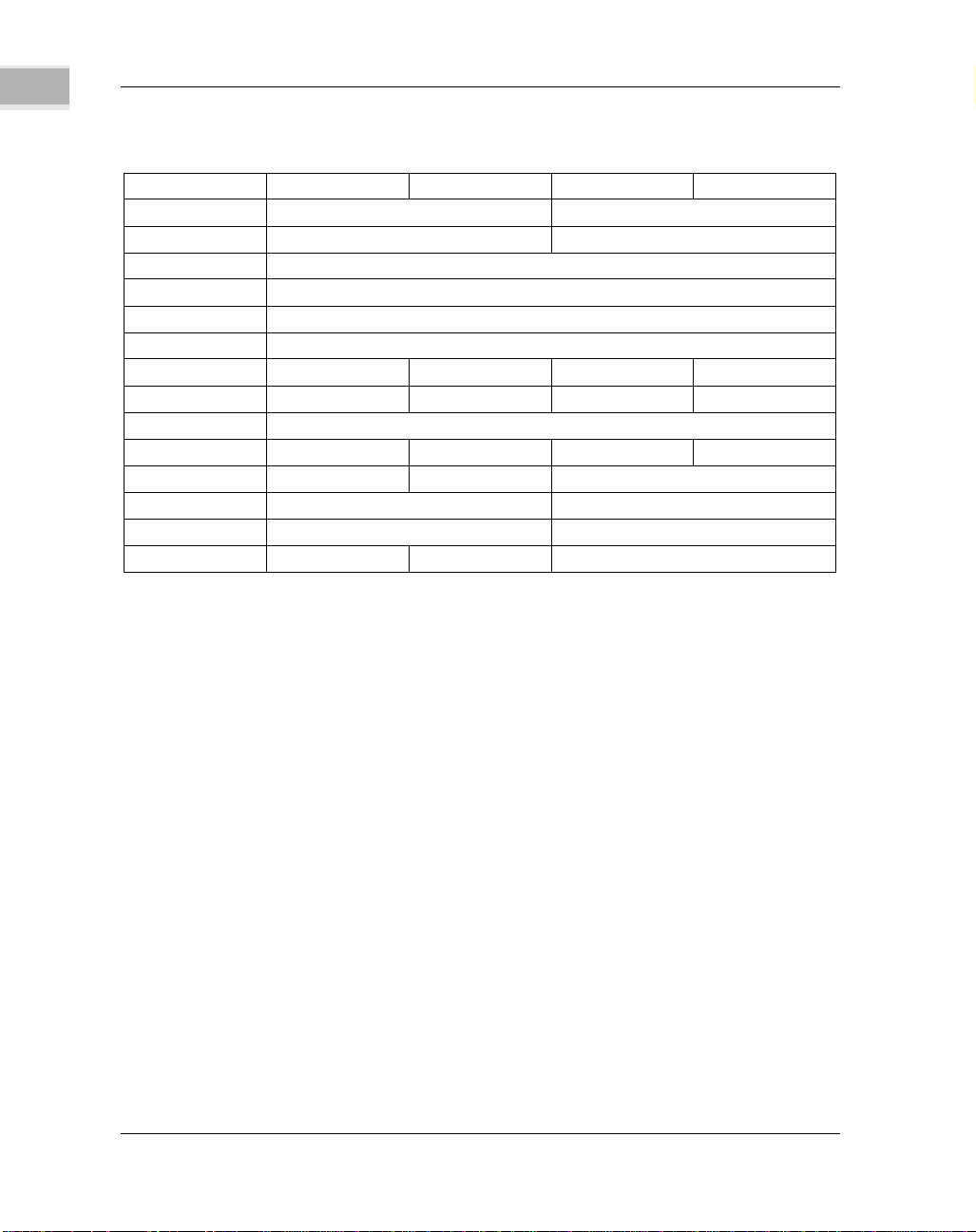
Equipment Supported
The following list shows the cont roller type assignments for SCSI controllers
explicitly supported by the SCSI firmware, and the drives supported by each.
/f3Note, however, that Motorola does not n ecessarily endorse or r ecommend
1-4
Page 5

Equipment Supported
any particular controller, nor does Motorola ass ume responsibility for the
operation of equipment manufactured by non-Motorola companies. Refer to
Appendix A for information on how to use this firmware program.
1
CONTROLLE
R
CODE TYPE
0D Floppy TEAC FD235J 2
0E Winchester Televideo
0F Winchester Common
10 Winchester Seagate WREN
11 Winchester M icropolis 1375 900475-11-2B 1,2
12 Streaming Archive Viper
DEVICE P ART
MANUFACTUR
ER/MODEL
1002921-1B 1,2,3
7000/7400/3500
Floppy
Tape
Command Set
Floppy
77774620 1,2
III 94161
Winchester Seagate WREN
IIIHH 94211
Winchester Seagate SWIFT
94351-126
Winchester Seagate SWIFT
94351-201
2060s
Tape
Streaming Archive Viper
2150s
Tape
Streaming Tanberg 3620
(8533) 60Mb
Tape
Streaming Tanberg 3640
(8534) 120M b
Tape
75912134 1,2
22100-007 1,2
22300-004 1,2
NUMBER NOTES
1,2,3
1,2
1,2
6
6
1-5
Page 6

1
GENERAL INFORMATION
CONTROLLE
R
CODE TYPE
CONTROLLE
R
CODE TYPE
13 Winchester Seagate WREN
14 Winchester Seagate ST
16 1/2" Tape Kennedy
17 Winchester Synchronous
DEVICE P ART
Streaming Tanberg 3660
Tape
Cassette TEAC MT-
Tape
DEVICE P ART
Winc hester Seagate WREN V
Winches ter Ma xt or 43 80S 2
Winches ter Ma xt or 87 60S 2
Winchester Seagate ST
Winchester Seagate ST
Winchester Seagate ST
Winchester Miniscribe 1,2
1/2" Tape HP 88780A 2
MANUFACTUR
ER/MODEL
(8535) 150M b
2ST/45S2
MANUFACTUR
ER/MODEL
IV 94171
94181
157N/M
125N/M
1096N
296N/M
9612/9662
Common
Command Set
NUMBER NOTES
6
2
NUMBER NOTES
77777000 1,2
77777750 2
1,2,5
1,2,5
1,2,5
1,2,5
U92-9662-0004 2
2
1-6
Page 7

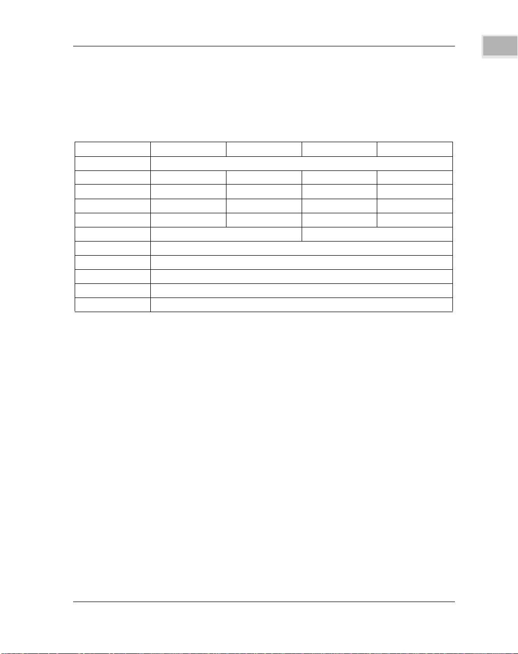
Equipment Supported
1
CONTROLLE
R
CODE TYPE
18 8mm Tape Exabyte EXB-
DEVICE P ART
Floppy 2,3
Devices Supported Under Common Command Set
Winchester Televideo
Floppy Televideo
Winchester Seagate WREN
Winchester Seagate WREN
Winchester Micropolis 1375 900475-11-2B 1,2
Winchester Seagate WREN
Winc hester Seagate WREN V
Winchester Seagate SWIFT
Winchester Seagate SWIFT
Winches ter Ma xt or 43 80S 2
Winches ter Ma xt or 87 60S 2,4
Devices Supported Under Synchronous Common Command Set
Winc hester Seagate WREN V
Winches ter Ma xt or 43 80S 2,4
Winches ter Ma xt or 87 60S 2,4
MANUFACTUR
ER/MODEL
8200
7000/7400/3500
7000/7400/3500
III 94161
IIIHH 94211
IV 94171
94181
94351-126
94351-201
94181
NUMBER NOTES
820010-009 2
1,2
1002921-1B 1,2,3
77774620 1,2
1,2
77777000 1,2,4
77777750 2,4
75912134 1,2
1,2
77777750 2,4
NO
TE:
1. Supported in firmware revision 1.0 and later.
2. Supported in firmware revision 2.0 and later.
1-7
Page 8

1
GENERAL INFORMATION
3. Common Command Set for floppy matches SCSI II rather than revision 17B.
4. Under Common Command Set the cache is not enabled on these devices.
5. Seagate /M means Motorola proprietary.
6. Firmware assembly order number is: 966096. Order number for tape drives is
(85xx) as shown with drive type. Order from: Tanberg Data A/S, Data
Storage Division, P.O. Box 9, Korsvoll N-0808, Osl o 8, Norwa y, Phone +47 2 18
90 90 or Tanberg Data Tech. Center, 1077 Business Center Circle, Newbury
Park, CA 91320, Pho n e +1 (80 5) 37 5- 2 50 0 .
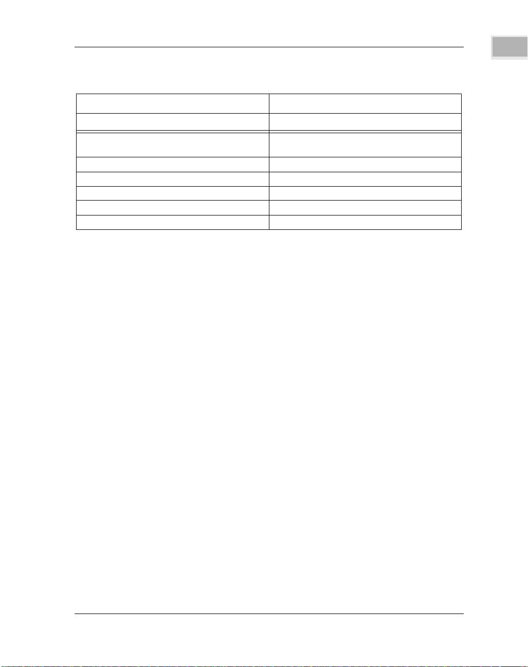
Related Documentation
The publications listed in the following table may provide additional helpful
information. If not shipped with this product, they may be purchased from
Motorola’s Literature Distribution Center, 616 West 24th Street, Tempe, AZ
85282; telephone (602) 994-6561. Non-Motorola documents may be obtained
from the sources listed.
MOTOROLA
DOCUMENT TITLE PUBLICATION NUMBER
MVME147 MPU VMEmodule User’s Manual MVME147
MVME147S MPU VMEmodule User’s
Manual
MVME147Bug Debugging Package User’s
Manual
MVME712A/MVME712AM/MVME712B
Transition
Module and MVME147P2 Adapter Board
User’s Manual
MVME712M Transition Module and
MVME147P2
Adapter Board User’s Manual
MVME147S
MVME147BUG
MVME712A
MVME712M
1-8
Page 9
DOCUMENT TITLE PUBLICATION NUMBER
M68000 16/32-Bit Microprocessor
Programmer’s
Reference Manual
M68000 Family VERSAdos System Facilities M68KVSF
Reference Manual
VERSAdos to VME Hardware and Software MVMEDOS
Configuration User’s Manual
M68000UM
NOTE: Although not shown in the abo v e list, each Motorola
Computer Group manual publication number is suffixed with
characters which represent the revision level of the document,
such as /D2 (the second revision of a manual); supplement
bears the same number as the manual but has a suffix such as
/A1 (the first supplement to the manual).
The following publications are available from the sources indicated.
Manual Terminology
1
MOTOROLA
SCSI Guide Book; Adaptive Data Systems, Inc., 2627 Pomona Boulevard,
Pomona, CA 91768
SCSI Small Computer Systems Interface; draft X3T9.2/82-2, Revision 14;
Computer and business Equipment Manufacturers Association, 311 First
Street, N.W., Suite 500, Washington, D.C. 20001
WD33C92 and WD33C93 SCSI Bus Interface Controller Data Manual; Western
Digital, 2445 McCabe Way, Irvine, CA 92714.
Common Command Set (CCS) of the Small Computer System Interface ( SCSI)
X3T9.2/85-52 - Revision 4B; Computer and Business Equipment
Manufacturer’ s Association, 311 First Street, N.W., Suite 500, Washington D.C.
20001
Manual Terminology
Throughout this manual, a convention has been maintained whereby data and
address parameters are preceded by a character which specifies the numeric
format as follows:
1-9
Page 10

1
GENERAL INFORMATION
$ dollar specifies a hexadecimal
number
% percent specifies a binary number
& ampersand specifies a decimal number
Unless otherwise specified, all address references are in hexadecimal
throughout this manual.
An asterisk (*) following the signal name for signals which are level significant
denotes that the signal is true or valid when the signal is low.
An asterisk (*) following the signal name for signals which are edge significant
denotes that the actions initiated by that signal occur on high to low transition.
In this manual, assertion and negation are used to specify forcing a signal to a
particular state. In particular, assertion and assert refer to a signal that is active
or true; negation and negate indicate a signal that is inactive or false. These
terms are used independently of the voltage level (high or low) that they
represent.
1-10
Page 11

Introduction
The SCSI firmware requests "canned" functions from SCSI disk controllers and
from SCSI tape controllers. Some of these functions are disk read and write,
disk format, tape read and write, and tape positioning operations. The
"canned" functions are only provided for the supported SCSI devices that are
listed in the Equipment Support ed section in Chapter 1.
If you want to perform a function that is not "canned", or you want to
communicate with SCSI devices that are not supported by the SCSI firmware,
you do not have to rewrite the SCSI firmware. Any SCSI operation may be
performed through the use of the custom SCSI packet.
A custom SCSI packet may be used for a variety of needs. Following are some
typical needs:
1. You need to perform a command on a suppor ted SCSI disk controller that
is not "canned" in the SCSI firmware. (For example, an offline COPY
command is not supported directly by the SCSI firmware. You may
perform this COPY command through the custom SCSI packet.)
2. You wish to interface the MVME147 module to a SCSI optical disk
controller.
3. You wish to request linked commands from a disk controller.
CUSTOM SCSI PACKETS
2
There are three classes of custom SCSI packets, described in the following
sections. They are:
Initiator role custom packet
TARGET enable custom packet
TARGET sequence custom packet
Initiator Role Custom Packet
The initiator role custom packet is shown in the following table.
Even Byte \
Odd Byte \
Page 12
2
CUSTOM SCSI PACKETS
FC B8 74 30
+$00 Controller LUN Device LUN
+$02 Status Byte 0 Status Byte 1 (No te 1)
+$04 Script Pointer (MSW)
+$06 Script Pointer (LSW)
+$08 Command Table Pointer (MSW) (Note 2)
+$0A Command Table Pointer (LSW) (Note 2)
+$0C 0000
+$0E Flag = 0 0 0 0
+$10 Scatter/Gather Count
+$12 0000
+$14 0 0 Function Code (1C)
+$16 Interrupt Level Vector Number
+$18 Status Byte 2 Status Byte 3 (No te 1)
+$1A 0 0 Retry Count
$00 00000xxx Controller logical unit
number
$01 00000xxx Device logical unit
number
$02 xxxxxxxx Status from SCSI
firmware (byte 0)
(Note 1)
$03 xxxxxxxx Status from SCSI
firmware (byte 1)
(Note 1)
$04 xxxxxxxx xxxxxxxx Script pointer (MSW)
$06 xxxxxxxx xxxxxxxx Script pointer (LSW)
$08 xxxxxxxx xxxxxxxx Command table
pointer (MSW) (Note
2)
$0A xxxxxxxx xxxxxxxx Command table
pointer (LSW) (Note
2)
$0C 00000000 00000000 Reserved
2-2
Page 13

Initiator Role Custom Packet
$0E 00000000 Initiator role
(TARGET
enable/sequence bit
undefined)
$0F 00000000 Reserved
$10 xxxxxxxx xxxxxxxx Scatter/gather entry
count. No retry
on firmware if
scatter/gather DMA
is used
because command
scatter/gath er ta ble
could
be modified after the
command is complete
if disconnect/reselect
occurred.
$12 00000000 00000000 Reserved
$14 00000000 Reserved
$15 00011100 SCSI function ($1C =
custom SCSI )
$16 00000xxx Interrupt level (7 to
0)(0 = polled mode)
$17 xxxxxxxx Vector number to use
upon return
$18 xxxxxxxx Status from SCSI
firmware (byte 2)
(Note 1)
$19 xxxxxxxx Status from SCSI
firmware (byte 3)
(Note 1)
$1A 00000000 Reserved
$1B 0000xxxx Retry count --
number of SCSI
command
retries (refer to
scatter/gathe r r etry
count
above)
2
2-3
Page 14

2
CUSTOM SCSI PACKETS
NOTES:
1. Refer to Chapter 3.
2. Command Table = 384 bytes
RAM work area.
This first class is used for command execution and/or message passing
through the MVME147 SCSI firmware while the module is playing the
initiator role. According to SCSI definition, an initiator is a SCSI device
(usually a host system) which requests an operation to be performed by
another SCSI device; a TARGET is a SCSI device which performs an operation
requested by an initiator. Initiator role custom packets request operations to
be performed by other SCSI devices. For the initiator role, certain data
structures are needed by the SCSI firmware. These are:
1. SCRIPT: A "script" is a sequence of SCSI bus phases that the initiator
expects the TARGET to perform when executing a requested command.
For example, a disk read (under SCSI rules) would typically require the
following SCSI bus phases:
MESSAGE-OUT: The IDENTIFY message is sent from the initiator to the
TARGET. This message contains the identification of the desired logical
unit of the selected disk controller that the initiator wishes to read. The
message also indicates whether the initiator is capable of reselection.
COMMAND: The Command Descriptor Block (CDB) is sent during the
command phase to specify the block number to read, the logical unit to
read from, the number of blocks to read, and whether the command is
linked.
DATA-IN: The actual data is transferred from the TARGET to the initiator
during the data-in phase.
STATUS: The disk controller sends the status of the command that was
executed during this phase.
MESSAGE-IN: During this phase, the disk controller sends a message
describing the execution of the command it just executed. The linked
command information would appear in the message sent during this
phase, for example.
BUS DISCONNECT: After a disk controller sends a command complete
message, it disconnects from the SCSI bus by releasing the BSY* signal.
The justification for a script is as follows. On the SCSI bus, the TARGET
is always the SCSI device that dictates the sequence of bus phases that
occurs during a communication with th e initiator (this communication is
2-4
Page 15

Initiator Role Custom Packet
commonly called a "thread"). The script allows the SCSI firmware to
follow the TARGET bus sequences and also allows the firmware to resume
a disconnected thread once a disconnect/ rese lect occurs. Because the SBC
allows "multithreading" of SCSI commands on the SCSI bus, a script is
necessary to resume any disconnected threads. Without a script, the SCSI
firmware would not have any way to check whether the TARGET
performed the command that was requested through the CDB.
The following table gives the possible SCSI bus phases.
2
PHASE
Bus Free No activity on the bus. SEL* and BSY* are not
Arbitration SCSI devices arbitrate for the use of the bus by
(Re)Selection One SCSI device selects another device by
Information Transfer Phases: Command
initiator
to TARGET
Status TARGET
Data
in
Data
out
Message
in
DIRECTION NOTES
activated.
activating BSY* and their ID.
activating SEL* along with its ID and th e ID for
the other device.
A command
tells the
TARGET
what is
requested by
the initiator.
The CDB is
passed
during this
phase.
The status of a particular command is passed to
to initiator
TARGET
to initiator
initiator
to TARGET
TARGET
to initiator
initiator. Examples: good, busy, check.
Data is transferred from the TARGET to the
initiator as a result of a data phase requested in
the CDB.
Data is transferred from the initiator to the
T A RGE T a s a result of a data pha se r equested in
the CDB.
Messages are sent to the initiator to send bus,
command, and controller information.
Examples: command complete, save data
pointer, restore data pointer, message reject.
2-5
Page 16

2
CUSTOM SCSI PACKETS
PHASE
Message
out
DIRECTION NOTES
initiator
to TARGET
Messages are sent to the TARGET to send bus,
command, and controller information.
Examples: identify, initiator detected error,
abort, device reset.
Scripts only specify the information transfer phases. The bus free, arbitration,
and selection phases do not need to be specified in a script. The script codes
that are understood by the MVME147 SCSI firmware are listed in the
following table. (Note that TARGET role scripts are described in the Target
Sequence Custom Packet section in this chapter.
CODE
$00 END OF SCRIPT Init iator
DISCONNECT TARGET
$04 COMMA N D PHASE Initi ator and TARGET
$08 DATA-OUT PHASE Initiator and TARGET
$0C DATA-IN PHASE Initiator and TARGET
$10 STATUS PHASE Initiator and TARGET
$14 MESSAGE-OUT PHASE Initiator and TARGET
$18 MESSAGE-IN PHASE Initiator and TARGET
$1C END OF SCRIPT TARGET
NOT DEFINED Initiator
$20 TARGET WAIT, TARGET
NO DISCONNECT
$24 TARGET WAIT, TARGET
DISCONNECT
$28 TARGET WAIT, TARGET
NO DISCONNECT
DATA RECEIVED
$2C TARGET WAIT, TARGET
DISCONNECT
DATA RECEIVED
BUS PHASES ROLE
2-6
Page 17

Initiator Role Custom Packet
If you suspect data integrity error, you can set up the SCSI script to execute the
data phase and then disconnect from the bus (script code 0x2c) or just return
as an intermediate return without disconnect from the bus (script code 0x28).
Firmware executes the data phase and then returns the firmware parity error
status, if any, command packet, and command table back to you.
You can examine the data as well as the firmware status to decide what SCSI
status should be returned to initiator. After the status is determined, a new
TARGET sequence command packet needs to be sent to firmware with status,
message (for message-in phase), and proper scripts to complete the SCSI bus
command.
For the previous disk read example, the script would be:
$14,$04,$0C,$10,$18,$00.
The above sequence of codes may be written anywhere in the MVME147accessible space. It may even be ROMed. The script pointer in the custom
SCSI packet is the address of the first entry of the script. In the example, it
would point to the $14. Therefore, the message-out phase should always be
the first phase in any initiator script.
2. COMMAND TABLE (384 bytes of RAM). The second data structure
required by the SCSI firmware for the execution of a custom SCSI packet
is a Command Table.
2
For unsupported controllers, the control of certain functions (parity checking,
DMA, linked commands, SCSI rules, DMA scatter/gather, SYNC/ASYNC
transfer) is dictated to the firmware through the status/flag byte of the
Command Table.
The CDB is one of the pieces of the command table. The user of the initiator
role custom SCSI packet loads the CDB to be passed to the SCSI target that is
to be selected. The initiator role custom SCSI packet has a Command Table
pointer which is the address of the first word of this data structure. Unlike the
script, the Command Table must be in MVME147-accessible RAM because the
firmware writes to portions of the table. All the user accessible pieces of the
Command Table are shown in the following table.
Even Byte \
Odd Byte \
2-7
Page 18

2
CUSTOM SCSI PACKETS
FC B8 74 30
+$00 Status/Flag Byte Retry Count (00)
+$02 Link Pointer (MSW)
+$04 Link Pointer (LSW)
+$06 Command Length
+$08 SCSI Command Descriptor Block (CDB)
+$0A SCSI Command Descriptor Block (CDB)
+$0C SCSI Command Descriptor Block (CDB)
+$0E SCSI Command Descriptor Block (CDB)
+$10 SCSI Command Descriptor Block (CDB)
+$12 SCSI Command Descriptor Block (CDB)
+$14 SCSI Status Initiator SCSI Address (0 t o 7)
+$16 Data Length (MSW)
+$18 Data Length (LSW)
+$1A Data Pointer (MSW) (Note 1)
+$1C Data Pointer (LSW) (Note 1)
+$1E Me ssa ge-In Length
+$20 Message-In Pointer (MSW)
+$22 Message-In Pointer (LSW)
+$24 Message-Out Length
+$26 Message-Out Pointer (MSW)
+$28 Message-Out Pointer (LSW)
+$2A Reserved
+$2C Reserved
.
.
.
+$60 Sector Number in Error (MSW)
+$62 Sector Number in Error (LSW)
+$64 SCSI Con troller Status 0 0
+$66 T ransfer Address
2-8
Page 19
Initiator Role Custom Packet
Even Byte \
Odd Byte \
FC B8 74 30
+$68 T ransfer Address
+$6A 0000
+$6C 0000
+$6E 0000
+$70 0000
+$72 Command Offset
+$74 Sense Data Block
.
.
.
+$9E Sense Data Block
2
$00 xxxxxxxx Status/flag byte
0....... Lnk -- link flag bit
disabled
1....... Lnk -- link command
tables, support
linked commands
.0...... Parity disabled
.1...... Parity enabled --
MVME147 checks
SCSI
bus parity
..0..... DMA on
..1..... DMA off flag --
disable DMA for data
out/in
...0.... CSCSI -- custom
sequence flag: checks
2-9
Page 20

2
CUSTOM SCSI PACKETS
status (Note 2)
...1.... CSCSI -- does not
check SCSI status
(Note 2)
....0... SCSI firmware uses
SCSI rules (Note 3)
....1... SASI mode flag --
firmware uses SASI
rules (Note 3)
.....1.. SG -- scatter/gather
enable, use data
points to
scatter/gather table.
During
custom SCSI packet,
you have to set this
bit if scatter/ gather
DMA operation is
required
.....0.. SG -- scatter/gather
disable
2-10
......1. SYNC -- synchronous
transfers enable
On INITIATOR role,
SCSI firmware
initiates synchronous
data transfer
request.
On TARGET role,
SCSI firmware
initiates synchronous
data transfer
request IF initiator
DOES NOT do so
before first data
phase.
Page 21

Initiator Role Custom Packet
......0. ASYNC --
asynchronous
transfers enable
$01 00000000 Retry count (must be
00)
$02 xxxxxxxx xxxxxxxx Link pointer (MSW) --
for linked commands.
Valid only if link flag
bit = 1
$04 xxxxxxxx xxxxxxxx Link pointer (LSW)
$06 xxxxxxxx xxxxxxxx Command length --
length of the CDB
(in bytes)
$08 xxxxxxxx xxxxxxxx SCSI command
descriptor block
(CDB)
SCSI draft revision
17B allows 12 bytes
maximum length
(Note 4)
$0A xxxxxxxx xxxxxxxx SCSI (CDB)
$0C xxxxxxxx xxxxxxxx SCSI (CDB)
$0E xxxxxxxx xxxxxxxx SCSI (CDB)
$10 xxxxxxxx xxxxxxxx SCSI (CDB)
$12 xxxxxxxx xxxxxxxx SCSI (CDB)
$14 xxxxxxxx SCSI status
On INITIATOR role,
this is the copy of
status on
$64.
On T ARGET role, you
can set SCSI status
here.
Bit 0(LSB), 5 and 6 is
vendor unique. Bit 7
is reserved. The
status set here is
ORed with
2
2-11
Page 22

2
CUSTOM SCSI PACKETS
the firmware status
($64) and sent to
initiator.
If you determine to
use bit 1-4, such as
data
parity error, the
firmware non-zero
status on
bit 1-4 has higher
priority. You should
load
this byte with the
appropriate status
and set
up the SCSI script for
status phase before
the
target sequence
packet is sent.
$15 xxxxxxxx Initiator SCSI addr ess
in TARGET mode (0
to 7)
(only used in
TARGET mode)
$16 xxxxxxxx xxxxxxxx Data length (MSW) --
number of bytes
expected during data-
in or data-out phase
$18 xxxxxxxx xxxxxxxx Data length (LSW)
$1A xxxxxxxx xxxxxxxx Data pointer (MSW) -
- to memory area
where firmwar e reads
(data out) or writes
(data-in) (contiguous
buffer)
$1C xxxxxxxx xxxxxxxx Data pointer (LSW)
2-12
Page 23

Initiator Role Custom Packet
$1E xxxxxxxx xxxxxxxx Message-in length --
bytes expected
during message-in
(max=258 for
extended
messages)
$20 xxxxxxxx xxxxxxxx Message-in pointer
(MSW) -- to RAM
buffer where
firmware stores
received
messages
$22 xxxxxxxx xxxxxxxx Message-in pointer
(LSW)
$24 xxxxxxxx xxxxxxxx Message-out length --
bytes expected
to be transferred in
message-out phase,
has to be non-zero if
message-out phase
is required (max=258
for extended
messages)
$26 xxxxxxxx xxxxxxxx Message-out pointer
(MSW) -- to RAM
buffer where
firmware takes
messages to
transfer to TARGET
$28 xxxxxxxx xxxxxxxx Message-out pointer
(LSW)
$2A xxxxxxxx xxxxxxxx Reserved
$2C xxxxxxxx Reserved
..
..
..
$60 xxxxxxxx xxxxxxxx Sector number in
error (MSW)
2
2-13
Page 24

2
CUSTOM SCSI PACKETS
$62 xxxxxxxx xxxxxxxx Sector number in
error (LSW)
$64 xxxxxxxx Initiator role - Status
byte from SCSI
controller
(unchanged)
TARGET r ole -
firmware determined
SCSI
status
$65 xxxxxxxx Reserved
$66 xxxxxxxx xxxxxxxx Trans fer address -- for
a read or writ e.
This is the address of
the next byte to be
transferred.
$68 xxxxxxxx xxxxxxxx Trans fer address -- for
a read or writ e.
This is the memory
address of the next
byte to be transfe rred.
.
.
.
.
$72 xxxxxxxx Command error
status byte (valid
following
a command error
$0B) -- SCSI
command in
error.
$73 xxxxxxxx Offset within packet.
$74 xxxxxxxx xxxxxxxx Sense data block
(controller-
dependent).
This is the
information returned
by the
2-14
Page 25

Initiator Role Custom Packet
controller follow ing a
check status and
a request sense data
command. Valid
informatio n if bit 14
(additional status)
is set.
This block is
firmware private area
and only
used on the
INITIATOR role.
.
.
$9E xxxxxxxx xxxxxxxx Sense data block
.
.
2
NOTE
S:
1. Points to scatter/gather table if scatter/gather bit = 1 in byte 0.
2. If = 0 and if status is "check", SCSI firmware interprets returned SCSI
status, and sends a request sense command to t he con troller; if status is =
busy, infinite retries are performed. If = 1, SCSI firmware does not read
the SCSI status from the command table, and returned status word in the
packet reflects only firmware status.
3. Must be 0. MVME147 SCSI firmware ONLY supports SCSI devices.
4. In TARGET mode, the CDBs is received from the SCSI bus and it will be
returned to the user without any modif ication with CDB length. When a
target LUN is not enabled or when ’target device reset’ or ’abort’ message
is received, the CDB received by the target role firmware will not be
returned to the user. Instead, a error code will be returned.
Example: Sending linked commands to a disk controller
You intend to implement a read-modify-write function for your particular
operating system. The benefit of linking commands on the SCSI bus is a better
utilization of bus bandwidth. When two commands are linked, the TARGET
does not disconnect between commands. After the message-in phase
completes one command, the TARGET switches to command phase for the
second command. The arbitration and selection phases are eliminated for the
2-15
Page 26

2
CUSTOM SCSI PACKETS
second command. The following linked command example may be
performed on the Archive 2150 disk controller (it supports linked commands).
The SCSI firmware does not support linked command with flag.
PACKET FOR THE LINKED COMMAND EXAMPLE:
PACKET DC.W $0400 CONTROLLER LEVEL=4, DEVICE LUN=0
DS.W 1 RETURNED STATUS WORD (BYTES 0 AND 1)+2
DC.L LSCRIPT SCRIPT POINTER +4
DC.L CT1 COMMAND TABLE POINTER +8
DC.W 0 RESERVED +C
DC.W 0 INITIATOR ROLE CUSTOM SEQUENCE +E
DC.W 0 RESERVED +10
DC.W 0 RESERVED +12
DC.W $001C FUNCTION CODE=CUSTOM SCSI SEQUENCE +14
DC.W $0260 INTERRUPT LEVEL 2, VECTOR $60 +16
DS.W 1 STATUS BYTES 2 AND 3 +18
DC.W 3 RETRY COUNT=3 +1A
SCRIPT for a READ followed by a WRITE:
2-16
LSCRIPT DC.B $14 MESSAGE OUT (IDENTIFY)
DC.B $04 COMMAND (READ)
DC.B $0C DATA IN
DC.B $10 STATUS
DC.B $18 MESSAGE IN
DC.B $04 COMMAND (WRITE)
DC.B $08 DATA OUT
DC.B $10 STATUS
DC.B $18 MESSAGE IN
DC.B $00 END OF SCRIPT
(LINKED COMMANDS REQUIRE AS MANY COMMAND TABLES AS
THERE ARE PIECES OF THE
LINKED COMMAND. I.E. FOR A READ/WRITE LINKED COMMAND, 2
TABLES ARE REQUIRED)
Page 27

Initiator Role Custom Packet
*****************************COMMAND TABLE FOR THE FIRST
COMMAND**************
CT1 DC.B %11000000
* X LINK FLAG ON
* X PARITY CHECKING ENABLED
* X DMA ENABLED
* X CUSTOM SEQ. FLAG=> FIRMWARE CHECKS STATUS
* X FIRMWARE USES SCSI RULES (RESELECT, ETC.)
* X RESERVED
X NO SCATTER/GATHER OPERATION
X ASYNC SCSI TRANSFER
DC.B 0 RETRY COUNT=0
DC.L CT2 THE ADDRESS OF THE SECOND COMMAND TABLE
DC.W 6 COMMAND LENGTH = 6 (GROUP 0 COMMAND)
DC.B $08 READ COMMAND
DC.B $00 LUN=0, BLOCK ADDR MSB=0
DC.B $00 BLOCK ADDR
DC.B $86 (FULL BLOCK ADDR=$00086)
DC.B $04 4 BLOCKS REQUESTED
DC.B $03 CONTROL BYTE: FLAG BIT=1, LINK BIT=1.
* see *NOTE below the second command table.
DC.B 00 DON’T CARE
DC.B 00 DON’T CARE
DC.B 00 DON’T CARE
DC.B 00 DON’T CARE
DC.B 00 DON’T CARE
DC.B 00 DON’T CARE
DS.B 01 USER’S STATUS BYTE IS STORED HERE
DC.B 07 SCSI INITIATOR ADDRESS = $07
DC.L $400 4 BLOCKS * $100 BYTES/BLOCK= $400 BYTES
DC.L BUFF DATA BUFFER ADDRESS
DC.W 1 MESSAGE IN AREA ALLOCATION= 1 BYTE
DC.L MSIN1 MESSAGE IN AREA POINTER
DC.W 1 MESSAGE OUT AREA ALLOCATION = 1 BYTE
DC.L MSOUT1 MESSAGE OUT AREA POINTER
DS.B 342 REMAINING OF THE 384 BYTE COMMAND TABLE
MSIN1 DS.B 1 MESSAGE IN AREA FOR COMMAND TABLE #1
MSOUT1 DC.B $C0 THE IDENTIFY MESSAGE FOR LUN 0, WITH
RESELECTION
BUFF DS.B $400 4 BLOCK DATA BUFFER
2
2-17
Page 28

2
CUSTOM SCSI PACKETS
*****************************COMMAND TABLE FOR THE WRITE
COMMAND**************
CT2 DC.B %01000000
* X LINK FLAG OFF
* X PARITY CHECKING ENABLED
* X DMA ENABLED
* X CUSTOM SEQ. FLAG=> FIRMWARE CHECKS STATUS
* X FIRMWARE USES SCSI RULES (RESELECT, ETC.)
* X RESERVED.
X NO SCATTER/GATHER
X ASYNC SCSI TRANSFER
DC.B 0 RETRY COUNT=0
DC.L 0 NO LINK ADDRESS PROVIDED.
DC.W 6 COMMAND LENGTH = 6 (GROUP 0 COMMAND)
DC.B $0A WRITE COMMAND
DC.B $00 LUN=0, BLOCK ADDR MSB=0
DC.B $00 BLOCK ADDR
DC.B $86 (FULL BLOCK ADDR=$00086)
DC.B $04 4 BLOCKS REQUESTED
DC.B $00 CONTROL BYTE: FLAG BIT=0, LINK BIT=0.
DC.B 00 DON’T CARE
DC.B 00 DON’T CARE
DC.B 00 DON’T CARE
DC.B 00 DON’T CARE
DC.B 00 DON’T CARE
DC.B 00 DON’T CARE
DS.B 01 USER’S STATUS BYTE IS STORED HERE
DC.B 07 SCSI INITIATOR ADDRESS = $07
DC.L $400 4 BLOCKS * $100 BYTES/BLOCK= $400 BYTES
DC.L BUFF DATA BUFFER ADDRESS
DC.W 1 MESSAGE IN AREA ALLOCATION= 1 BYTE
DC.L MSIN2 MESSAGE IN AREA POINTER
DC.W 1 MESSAGE OUT AREA ALLOCATION = 1 BYTE
DC.L MSOUT2 MESSAGE OUT AREA POINTER
DS.B 342 REMAINING OF THE 384 BYTE COMMAND TABLE
MSIN2 DS.B 1 MESSAGE IN AREA FOR COMMAND TABLE #1
MSOUT2 DC.B $00 NO MESSAGE OUT PHASE FOR THE SECOND
COMMAND.
2-18
Page 29

TARGET Enable Custom Packet
Note
A linked command with the flag bit set is not supported,
and the flag bit is ignored if it is set.
TARGET Enable Custom Packet
The TARGET enable custom packet is shown in the following table.
Even Byte \
Odd Byte \
FC B8 74 30
+$00 Controller LUN Device LUN
+$02 Status Byte 0 Status Byte 1 (No te 1)
+$04 Not Used
+$06 Not Used
+$08 Command Table Pointer (MSW) (Note 2)
+$0A Command Table Pointer (LSW) (Note 2)
+$0C 0000
+$0E Flag = C 0 0 0
+$10 0000
+$12 0000
+$14 0 0 Function Code (1C)
+$16 Interrupt Level Vector Number
+$18 Status Byte 2 Status Byte 3 (No te 1)
+$1A 0 0 Retry Count
2
$00 00000xxx Controller logical unit
number
$01 00000xxx Device logical unit
number
$02 xxxxxxxx Status from SCSI
firmware (byte 0)
(Note 1)
2-19
Page 30

2
CUSTOM SCSI PACKETS
$03 xxxxxxxx Status from SCSI
firmware (byte 1)
(Note 1)
$04 xxxxxxxx xxxxxxxx Not used
$06 xxxxxxxx xxxxxxxx Not used
$08 xxxxxxxx xxxxxxxx Command table
pointer (MSW) (Note
2)
$0A xxxxxxxx xxxxxxxx Command table
pointer (LSW) (Note
2)
$0C 00000000 00000000 Reserved
$0E 1....... TARGET role
.1...... TARGET enable
..000000 Reserved
$0F 00000000 Reserved
$10 00000000 0000 0000 Reserved
$12 00000000 0000 0000 Reserved
$14 00000000 Reserved
$15 xxxxxxxx SCSI function ($1C =
Custom SCSI
sequence)
$16 00000xxx Interrupt level (7 to 1)
$17 xxxxxxxx Vector number to use
upon return
$18 xxxxxxxx Status from SCSI
firmware (byte 2)
(Note 1)
$19 xxxxxxxx Status from SCSI
firmware (byte 3)
(Note 1)
$1A 00000000 Reserved
$1B 00000000 Retry count must be 0
NOTES:
2-20
1. Refer to Chapter 3.
2. Command table = 384 bytes
RAM work area.
Page 31

TARGET Enable Custom Packet
This second "class" of custom packets is used to enable TARGET role service
by the MVME147 SCSI firmware. All eight SCSI-defined logical units can be
independently serviced through the firmware. Each logical unit needs to be
enabled separately. In other words, a TARGET enable packet is sent for each
logical unit that you want to service. The TARGET enable packet should not
be deallocated even after TARGET is enabled and command is received (final
return for TARGET enable). It is recommended that you use the same packet
for TARGET enable and TARGET sequence. The last packet should be saved
until the next TARGET command is received.
Packet description:
WORD $00: CONTROLLER LUN -- This is the target SCSI address of the
MVME147. Because target firmware already knows the SCSI
address this field is used to compare with the known target
SCSI address. If the address does not match, an ID error is
reported when the packet is received.
DEVICE LUN -- This number (0 through 7) specifies which
TARGET logical unit is to be enabled. All eight may be
enabled, but only one is enabled per TARGET enable call.
WORD $02: STATUS bytes 0 and 1 -- These status bytes are the codes
returned to you by the firmware. (For code definitions, refer
to Chapter 3.)
2
WORDS $04 and $06:
SCRIPT POINTER -- The script pointer is not used by the
firmware for the TARGET enable call.
WORDS $08 and $0A:
COMMAND TABLE POINTER -- This is the pointer to the
command table (384 bytes of RAM). Each TARGET logical
unit needs one command table. No sharing of command
tables is allowed among the enabled logical units. When a
TARGET command is complete, this command table must not
be deallocated because of future use. However, the command
table area could be used by subsequent TARGET commands.
WORD $0E=$C000:
This code classifies the custom packet as a TARGET enable
call to the firmware.
WORD $14: The code of $1C classifies the packet as a custom packet.
2-21
Page 32

2
CUSTOM SCSI PACKETS
WORD $16: The interrupt level must be no-zero because TARGET role
support is not used in non-interrupt mode. (If TARGET role
support were done in polled mode, nothing else would be
able to run on the MVME147 other than the TARGET
firmware because the microprocessor would poll for a
selection as a TARGET.) The vector number is used to
provide the return path to you. (You take over that vector and
point it to your service routine.)
IMPLEMENTATION NOTE: It is highly recommended that
you assign a unique return vector for each enabled TARGET
logical unit in order to keep the service of each LUN separate
and independent from the other LUNs.
WORD $18: Not used by the firmware for the TARGET enable call.
WORD $1A: Not used by the firmware for the TARGET enable call.
TARGET Sequence Custom Packet
The TARGET sequence custom packet is shown in the following table.
Even Byte \
Odd Byte \
FC B8 74 30
+$00 Controller LUN Device LUN
+$02 Status Byte 0 Status Byte 1 (No te 1)
+$04 Script Pointer (MSW)
+$06 Script Pointer (LSW)
+$08 Command Table Pointer (MSW) (Note 2)
+$0A Command Table Pointer (LSW) (Note 2)
+$0C 0000
+$0E Flag = 8 0 0 0
+$10 0000
+$12 0000
+$14 0 0 Function Code (1C)
+$16 Interrupt Level Vector Number
+$18 Status Byte 2 Status Byte 3 (No te 1)
2-22
Page 33

TARGET Sequence Custom Packet
+$1A 0 0 Retry Count
$00 00000xxx Controller logical unit
number
$01 00000xxx Device logical unit
number
$02 xxxxxxxx Status from SCSI
firmware (byte 0)
(Note 1)
$03 xxxxxxxx Status from SCSI
firmware (byte 1)
(Note 1)
$04 xxxxxxxx xxxxxxxx Script pointer (MSW)
$06 xxxxxxxx xxxxxxxx Script pointer (LSW)
$08 xxxxxxxx xxxxxxxx Command table
pointer (MSW) (Note
2)
$0A xxxxxxxx xxxxxxxx Command table
pointer (LSW) (Note
2)
$0C 00000000 00000000 Reserved
$0E 1....... TARGET role
.0...... TARGET sequence
..000000 Reserved
$0F 00000000 Reserved
$10 00000000 00000000 Reserved
$12 00000000 00000000 Reserved
$14 00000000 Reserved
$15 xxxxxxxx SCSI function ($1C =
custom SCSI
sequence)
$16 00000xxx Interrupt level (7 to 1)
$17 xxxxxxxx Vector number to use
upon return
$18 xxxxxxxx Status from SCSI
firmware (byte 2)
(Note 1)
2
2-23
Page 34

2
CUSTOM SCSI PACKETS
$19 xxxxxxxx Status from SCSI
firmware (byte 3)
(Note 1)
$1A 00000000 Reserved
$1B 0000xxxx Retry count must be 0
NOTES:
1. Refer to Chapter 3.
2. Command Table = 384 bytes
RAM work area.
This third "class" of custom packets is used to service received commands and
messages for an enabled MVME147 TARGET logical unit. When an initiator
selects the MVME147 as a TARGET, the firmware switches to TARGET role,
determines which logical unit is desired by the initiator, and returns to the
TARGET service routine (through the vector supplied in the TARGET enable
packet) for user service of the initiator request. If the initiator that selected the
MVME147 as a TARGET does not send an illegal message, the TARGET role
firmware sequences the SCSI bus to the command phase, read in a CDB, store
the CDB in the command table provided through the TARGET enable packet,
and return through the vector provided for the selected logical unit for
command service. If the command was received, a final status of $xx17 or an
intermediate status of $xx06 is stored in the status word of the particular LUN
packet. The final status code of $xx17 is returned if an IDENTIFY WITH
RESELECTION message was received. The intermediate status code of $xx06
is returned if ATN* was not asserted during selection or if an IDENTIFY
WITHOUT RESELECTION message was received. You then use a TARGET
sequence packet to service the command.
IMPLEMENTATION NOTE: The SCSI firmware DOES provide information
to you as to which SCSI initiator is requesting service from the TARGET in
command table byte offset $15.
2-24
Packet description:
WORD $00: CONTROLLER LUN -- This binary number must match the
SCSI level of the MVME147 as in Target Enable Custom
Packet.
DEVICE LUN -- This number identifies the particular logical
unit to service an initiator request.
WORD $02: STATUS bytes 0 and 1 -- This is the firmware status word that
tells you how your packet was serviced (finished, error, etc.).
Page 35

Note
TARGET Sequence Custom Packet
2
WORDS $04 and $06:
SCRIPT POINTER -- The address of the TARGET script to be
performed to service the initiator request.
In TARGET role, the MVME147 controls the SCSI bus. The
TARGET script tells the firmware which information transfer
phases to cycle through to service the initiator request that
was encoded in the CDB.
In TARGET role, the names of the information transfer
phases are consistent with initiator role. By SCSI
definition, transfer direction is always referenced to the
initiator. That is, the message in pha se is a message tr ansfer
INTO the initiator. For T ARGET ro le the message-in phase
is still INTO the initiato r (notice it is OUT of th e TARGET).
TARGET scripts to service commands do not include
command phases. Below are examples of TARGE T scripts for
two CDBs; one is a receive CDB and the other is a send CDB.
Example 1: Receive (peripheral device type = processor
devices)
CDB byte 0: $08 Command is a receive
CDB byte 1: $20 The desired LUN is 1
CDB byte 2: $00 Allocation length MSB
CDB byte 3: $04 Allocation length
CDB byte 4: $00 Allocation length LSB
CDB byte 5: $00 Control byte=0: no link, no flag
Target script for example 1:
DC.B $0C DATA-IN PHASE
DC.B $10 STATUS PHASE
DC.B $18 MESSAGE-IN PHASE
DC.B $1C END OF TARGET SCRIPT
The command table contains the information required to
carry out the bus phase. For example, the data pointer tells
the firmware where the buffers are located in MVME147accessible memory.
1. During the data-in phase, the $400 bytes are sent to the initiator.
2. During the status phase, the GOOD status is sent to the initiator.
2-25
Page 36

2
CUSTOM SCSI PACKETS
3. During the message-in phase, the COMMAND COMPLETE message is
sent to the initiator.
4. The END OF TARGET SCRIPT code causes the firmware to disconnect
from the bus and return to you (through the vector provided in the
TARGET sequence packet) with a final status of $xx18, indicating the
TARGET script was completed successfully.
Example 2: Send (peripheral device type = processor d evices):
CDB byte 0: $0A Command is a write
CDB byte 1: $20 The desired LUN is 1
CDB byte 2: $00 Allocation length MSB
CDB byte 3: $03 Allocation length
CDB byte 4: $00 Allocation length LSB
CDB byte 5: $00 Control byte=0: no link, no flag
Target script for example 2:
DC.B $08 DATA OUT PHASE
DC.B $10 STATUS PHASE
DC.B $18 MESSAGE IN PHASE
DC.B $1C END OF TARGET SCRIPT
2-26
1. During the data-out phase, the initiator writes data to the MVME147 . The
byte count is $300.
2. During the status phase, the GOOD status is sent.
3. During the message-in phase, the COMMAND COMPLETE message is
sent.
4. The end of TARGET script code causes the firmware to disconnect from
the SCSI bus and return to you through the vector provided in the
TARGET sequence packet.
WORDS $08 and $0A:
COMMAND TABLE POINTER -- The address of the
TARGET role command table. Below is a description of the
requirements of the TARGET command table.
TARGET COMMAND TABLE DESCRIPTION:
CT word 00: (Byte 0 -- status/flag byte.)
Bit assignments:
Page 37

TARGET Sequence Custom Packet
D7 = Not used by the TARGET role firmware. (This is the link bit.
Command linking is not accomplished with the use of this
bit.)
D6 = Not used by the TARGET role firmware. (This is the parity
bit. )
D5 = Not used by the TARGET role firmware. (This is the DMA
disables bit. DMA is used in TARGET role: 0 = DMA, 1 = no
DMA)
D4 = MUST be zer o. No t used b y the TARGET role firmware. (This
is the interpret bit and only relevant for initiator role.)
D3 = Not used by the TARGET role firmware. (This is the
SASI/SCSI rule bit. The TARGET role module determines
which rule to follow by the initiator assertion of ATN and the
re-select option bit of the IDENTIFY message.)
D2 = This is a scatter/gather bit. If DMA is enabled, the data
pointer in the command table could be used to point to the
scatter/gather table if this bit is 1.
D1 = 1 = SYNC transfer enable.
0 =ASYNC transfer enable.
D0 = Reserved.
2
(Byte 01): Not used by the TARGET role firmware. Must be set to $00.
CT words $02 and $04: LINK POINTER. Not used by the TARGET role
firmware.
CT word $06: COMMAND LENGTH. Not used by the TARGET sequence ca ll.
(The CDB received from initiator is stored in the command table that was
provided in the TARGET enable call. You may use the same command tables
for the enable and sequence calls to interpret receive CDB, but the TARGET
sequence call does not make use of the command length and of the CDB itself.)
CT words $08 through $12: COMMAND DESCRIPTOR BLO CK. Not used by
the TARGET sequence call. (Refer to CT word 06 above for command length.)
CT word $14, even byte: User SCSI STATUS. For a TARGET sequence, you can
set the vendor unique bits in the status byte. The MVME147 SCSI firmware
sends the contents of this byte ORed with the firmware SCSI status byte in
offset $64 if a status phase code is encountered in the TARGET script. (Odd
byte $15: initiator SCSI address which is interfacing with the TARGET role
firmware.)
2-27
Page 38

2
CUSTOM SCSI PACKETS
CT words $16 and $18: DATA LENGTH. The number of bytes to transfer
during either the data-in or the data-out phase. Not used if DMA is enabled
and SG bit is set in status/fla g byte in word o.
CT words $1A and $1C: DATA POINTER. If a DATA-IN code is in the
TARGET script, the firmware starts transferring data FROM the contiguous
data buffer pointed to by this pointer. If a DATA-OUT code is in the TARGET
script, the firmware starts transferring data TO the contiguous data buffer
pointed to by this pointer. This pointer points to SG table if DMA S G is used.
CT word $1E: MESSAGE-IN LENGTH. Not used by the TARGET role
firmware for the message byte count in the message-in phase.
CT words $20 and $22: M ESSAGE-IN POINTER. If a message-in code is in the
TARGET script, the firmware sends the messages from message-in buffer
where this pointer points.
CT word $24: MESSAGE-OUT LENGTH. Not used by the TARGET role
firmware.
CT words $26 and $28: MESSAGE-OUT POINTER. If the initiator that is
threaded to the MVME147 sends an extended message to the MVME147, the
firmware stores it in the message buffer that is pointed to by this pointer. (The
ATN condition is only serviced if the ATN signal is asserted during selection
or certain phases. The initial IDENTIFY message is handled internally by the
firmware for threading purposes. If the ATN condition arises during a phase
that can be serviced, the message that is received from the initiator is stored in
the buffer pointed to by this message-out pointer.)
2-28
CT word $64, even byte : TARGET role firmware SCSI status byte set by
firmware during target sequence packet execution..
The remaining bytes of the command table are reserved.
Packet word $0E=$8000:
This word classifies the custom SCSI packet as a TARGET sequence.
Packet word $14=$001C:
This word classifies the packet as a custom SCSI sequence.
Packet word $16:
The interrupt level must be non-zero because TARGET role is only supported
for interrupt mode. The vector number provides the return path for the
firmware to you.
Packet word $18:
Page 39

TARGET Sequence Custom Packet
STATUS BYTES 2 and 3. Not used by the TARGET role firmware.
Packet word $1A:
RETRY COUNT. Not used by the TARGET role firmware.
2
2-29
Page 40

2
CUSTOM SCSI PACKETS
2-30
Page 41

PACKET RETURN STATUS
Packet Return Status
When packets are returned to the user, they contain two status words: one
with an offset of $02 and the other with an offset of $18, as shown in the tables
below, respectively. The first table details the status codes contained in the
word at offset $02. Refer to the Interface Rules for the SCSI Firmware section in
Chapter 5 for additional information. Also, refer to the command table
returned fields.
Status word offset $02
1508 0700
3
Control Flags
Bits 12-8 (reserved)
Bit 13 (RTE FLAG) (of interest only to the
programmer)
1 = This return was not preceded by an
interrupt and is the first return since
command entry. In this case, no RTE is
required.
0 = This return was preceded by an interrupt
and is not the first return, therefore,
an RTE is required to continue processing from where an interrupt occurred.
Register A3 has a pointer to a register
save area (D0-D7, A0-A6).
Bit 14 (ADDITIONAL ST ATUS)
1 = External status is valid.
0 = External status is not valid.
Status Code (Refer to Table 3-1)
Page 42

3
PACKET RETURN STATUS
Bit 15 (FINALSTAT)
1 = Intermediate return.
0 = Final status.
The script processing completed successfully, OR the script processing
encountered a fatal error.
Note
*(L1
*(L2
*(L3
*(L4
Status word offset $18
This does not mean that the operation that the
user requested on the SCSI was successful. The
status is contained in the status code (bits 7-0.)
3-2
1512 1108 0704 0300
SCSI
Phase Reserved Flags
Status (0 if not used)
| Bit 0
(RES)
Reserved)
Bit 1
(ILI)
Incorrect
length
indicator.
Request Sense
Page 43

Bit 2 (EOM)
End of
media.
Bit 3 (FM)
Filemark
Bit 4 (COMMAND
RETRY)
1 = Retries were
performed.
Bit 5 (COMMAND RE-
TRY OVERFLOW)
1 = Retry overflow.
The command
was retried
"retry count"
times.
Packet Return Status
3
Bits 6 and 7 (reserved)
*(L1
*(L2
*(L3
*(L4
*(L5
*(L6
*(L7
Return Status Packet
Even Byte \
Odd Byte \
3-3
Page 44

3
PACKET RETURN STATUS
FC B8 74 30
+$00
+$60 Block Number in Error (MSW)
+$62 Block Number in Error (LSW)
+$64 SCSI Con troller Status 0 0
+$66 T ransfer Address
+$68 T ransfer Address
+$6A 0000
+$6C 0000
+$6E 0000
+$70 0000
+$72 Command Offset
+$74 Sense Data Block
+$9E Sense Data Block
.
.
.
.
$60 xxxxxxxx xxxxxxxx Block number in err or
(MSW) -- This is the
returned information
bytes taken from
bytes
3-6 following an err or
from a SCSI device
and a request sense
command.
$62 xxxxxxxx xxxxxxxx Block number in err or
(LSW)
$64 xxxxxxxx Status byte from SCSI
controller
(unchanged)
$65 xxxxxxxx Reserved
$66 xxxxxxxx xxxxxxxx Trans fer address -- for
a read or writ e.
3-4
Page 45

Packet Return Status
This is the memory
address of the next
byte
to be transferred.
$68 xxxxxxxx xxxxxxxx Trans fer address -- for
a read or writ e.
.
.
$72 xxxxxxxx Command error
$73 xxxxxxxx Offset within packet.
$74 xxxxxxxx xxxxxxxx Sense data block
.
.
$9E xxxxxxxx xxxxxxxx Sense data block
.
.
status byte (valid
following
a command error
$0B)
.
.
3
Table 3-1. Packet Status Codes
CODE
MEANING NOTES
Intermediate Return
Codes
$02 Wait for interrupt; command
door open. OK to send new
commands for other devices
to firmware.
$04 A message has been received.
You must interpret.
$06 (TARGET mode) received a
command from initiator, no
disconnect allowed.
$08 (TARGET mode) data
received from initiator, user
must interpret then continue
with new t_seq.
1
1
1
1,9
3-5
Page 46

3
PACKET RETURN STATUS
Table 3-1. Packet Status Codes
CODE
MEANING NOTES
Intermediate Return
Codes
$09 (TARGET mode) data
received from initiator with
parity error, user must
interpret then continue with
new t_seq.
Final Return Codes
$00 GOOD. Script processing is
OK.
$01 Undefined problem. 2
$02 TARGET has Received Data
without error, and user may
interpret then continue with
new t_seq.
$03 Interrupt handler was
entered with no pending IRQ
($F00050).
$04 Reselection not expected
from this TARGET.
$05 TARGET thinks it is working
on linked commands but the
command table does not.
$06 Linked command has error
status code; command has
been aborted.
$07 Received an illegal message. 2
$08 The message we have tried to
send was rejected.
$09 TARGET Encountered a
parity error in data
transfer(in) phase and user
must interpret then continue
with new t_seq.
1,9
2
2
2
2
2
2
2
2
3-6
Page 47

Table 3-2. Packet Status Codes (cont’d)
Packet Return Status
3
CODE
$0A SCSI bus reset received (A1 pointing to packet list). (Refer to the
SCSI Bus Reset Packet section in Chapter 7.)
$0B Command error (bad command code, bad timing, or command
door was closed when a command was received) = 00. Custom
SCSI sequence: controller level not equal to "147 local level", or
interrupt no t on. Fo rmat: for mat with d efects on a con - tro ller t ype
not supported. Controller reset: controller not SCSI type. Space
(tape): undefined mode. Mode select (tape): undefined controller
type. Mode sense (tape): undefined controller type.
$0C Size error (invalid format code). 2
$0D Bad ID in packet or local ID. 2
$0E Error in attach (not previously attached, bad device LUN,
unsupported controller).
$0F Busy error (device has a command pending). 2
$10 There is disagreement between initiator and TARGET regarding
the number of bytes that are to be transferred.
$11 Received a BERR* while in DMA mode. 2
$12 Selection time-out. TARGET does not respond. 2
$13 SCSI protocol violation. Controller reset: controller not SCSI. 2
$14 Script mismatch. CHECK STATUS. If SCSI status within
command table (offset $14 for initiator role) is zero, then assume
script mismatch, otherwise use SCSI packet status.
$15 Script mismatch. The TARGET sequence of operation did not
match the script.
$16 I llegal SCSI state machine transition. 2
$17 Command has been received (TARGET r ole). Disconnect allowed. 2
$18 Script complete in TARGET role. 2
$19 Script complete and new command loaded (TARGET role linked
command).
$1A TARGET module called. TARGET role not supported. 2
MEANING NOTES
2
2
2
2
2
2
2
3-7
Page 48

3
PACKET RETURN STATUS
Table 3-3. Packet Status Codes (cont’d)
CODE
$1B TARGET module rejected an initiator message and returned with
this status to a particular LUN service routine.
$1C TARGET module sent a check status wi th an "illegal reques t" sense
block to some initiator because the particular LUN that the
initiator wanted was not enabled.
$1D TARGET module sent a busy status to the calling initiator because
the particular LUN that the initiator wanted was already busy
servicing a command.
$1E TARGET received ABORT message from the SCSI initiator. 2
$1F TARGET received DEVICE RESET message from the SCSI
initiator.
MEANING NOTES
Request-Sense-Data Error-Class 7 Codes
(Controller-Dependent)
$20 NO SENSE. Indicates that there is no specific sense key
information to be reported for the designated logical unit.
$21 RECOVERED ERROR. Indicates that the last command
completed successfully with some recovery action performed by
the TARGET. Details can be determined by examining the
additional sense bytes and information bytes.
$22 NOT READY. Indicates that the logical unit addressed cannot be
accessed. Operator intervention may be required to correct this
condition.
$23 MEDIUM ERROR. Indicates that the TARGET detected a
nonrecoverable error co ndition that was probably caused by a flaw
in the medium or an error in recording data.
$24 HARDWARE ERROR. Indicates that the TARGET detected a
nonrecoverable hardware failure (for example, controller failure,
device failure, parity er ror, etc.) while performing the command or
during self test.
$25 ILLEGAL REQUEST. Indicat es that ther e was an illegal para meter
in the command descriptor block or in the additional parameters
supplied as data.
2
2
2
2,3
2,3
2,3
2,3
2,3
2,3
3-8
Page 49

Table 3-4. Packet Status Codes (cont’d)
Packet Return Status
3
CODE
$26 UNI T ATTENTION. Indicates that the removable media may
have been changed or the TARGET has been reset.
$27 D ATA PROTECT. I ndicates that a command that reads or writes
the medium was attempted on a block that is protected from this
operation.
$28 BLANK CHECK. Indicates that a write-once read-multiple dev ice
or a sequential access device encountered a blank bl ock while
reading or a write-once read-multiple device encountered a
nonblank block while wri tin g.
$29 VENDOR UNIQUE. Used for reporting vendor unique conditions
(for Saber AP = format complete).
$2A COPY ABORTED. Indicates that a copy or a copy and verify
command was aborted due to an error condition.
$2B ABORTED COMMAND. Indicates that the TARGET aborted the
command. The init iator may be able to reco ver by trying the
command again.
$2C EQUAL. Indicates a search data command has satisfied an equal
comparison.
$2D VOLUME OVERFLOW. Indicates that a buffered peripheral
device has reached an end-of-medium and data remains in the
buffer that has not been written to the medium. A recover
buffered data command may be issued to read the unwritten data
from the buffer.
$2E MISCOMPARE. Indicates that the source data did not match the
data read from the medium.
$2F RESERVED. This sense key is reserved. 2,3
MEANING NOTES
SCSI Status Returned in Status Phase
$31 SCSI status = $02. CHECK. 2,4
$32 SCSI st atus = $04. CONDITION MET. 2,4
$34 SCSI status = $08. BUSY. 2,4
$38 SCSI status = $10. INTERMEDIATE/GOOD. 2,4
$3A SCSI status = $14. INTERMEDIATE/CONDITION MET/GOOD. 2,4
$3C SCSI status = $18. RESERVATION CONFLICT. 2,4
2,3
2,3
2,3
2,3
2,3
2,3
2,3
2,3
2,3
3-9
Page 50

3
PACKET RETURN STATUS
Table 3-5. Packet Status Codes (cont’d)
CODE
MEANING NOTES
Request-Sense-Data Error-Class 0 through 6 Codes
(Controller-Dependent)
$40 NO ERROR STATUS. 2,5,6
$41 NO INDEX SIGNAL. 2,5,6
$42 NO SEEK COMPLETE. 2,5,6
$43 WRITE FAULT . 2,5,6
$44 DRIVE NOT READY. 2,5,6
$45 DRIVE NOT SELECTED. 2,5,6
$46 N O TRACK 00. 2,5,6
$47 MULTIPLE DRIVES SELECTED. 2,5,6
$49 CARTRIDGE CHANGED. 2,5,6
$4D SEEK IN PROGRESS. 2,5,6
$50 ID ERROR. ECC error in the data field. 2,5,7
$51 DATA ERROR. Uncorrectable data error during a read. 2,5,7
$52 ID ADDRESS MARK NOT FOUND. 2,5,7
$53 DATA ADDRESS MARK NOT FOUND. 2,5,7
$54 SECTOR NUMBER NOT FOUND. 2,5,7
$55 SEEK ERROR. 2,5,7
$57 WRITE PROTECTED. 2,5,7
$58 CORRECTABLE DATA FIELD ERROR. 2,5,7
$59 B AD BLOCK FOUND. 2,5,7
$5A FORMAT ERROR. (Check track command. 2,5,7
$5C UNABLE TO READ ALTERNATE TRACK ADDRESS. 2,5,7
$5E ATTEMP TED TO DIRECTLY ACCESS AN ALTERNATE TRACK. 2,5,7
$5F SEQUENCER TIME OUT DURING TRANSFER. 2,5,7
$60 INVALID COMMAND. 2,5,8
$61 ILLEGAL DISK ADDRESS. 2,5,8
$62 ILLEGAL FUNCTION. 2,5,8
$63 VOLUME OVERFLOW. 2,5,8
3-10
Page 51

Packet Return Status
3
NO
TES
:
1. Intermediate return codes. Bit 15-1, actual word=$80xx, $90xx, etc.
2. Final return codes.
3. Sens e key s tatus co des for Req uest-Sen se-Data er ror -- cl ass 7. A n of fset of $20 i s
added to all sense key codes.
4. The SCSI status sent from the controller is ANDed with $1E, shifted right one
bit, and $30 added.
5. Sense key status codes for Request-Sense-Data error -- classes 0-6. An offset of
$40 is added to all sense key codes.
6. Drive error codes.
7. Controller error codes.
8. Command errors.
9. Intermediate return codes, the no disconnection is allowed according to the
script.
3-11
Page 52

3
PACKET RETURN STATUS
3-12
Page 53

SCSI FIRMWA RE
INTERRUPT STRUCTURE
SCSI Firmware Interrupt Structure
The SCSI interface firmware was designed for processor efficiency. Whenever
the SCSI bus is in a state that does not need monitoring, the firmware releases
the processor so it may perform other functions such as user tasks and lower
priority events. In these cases, an interrupt brings processor control back to
the firmware.
A return vector is provided to the SCSI firmware in all cases through the
packet pointed to by register A2. Whenever the firmware returns to the user
through this return vector, it flags whether the processor was brought back to
the firmware through an external interrupt. This flagging is done by the RTE
FLAG bit in the status word stored in the user packet. If the bit = 1, no RTE is
to be performed by the user. If the bit = 0, eventually an RTE is required by the
user to return the processor to the interrupted task.
Similarly, whenever the RTE instruction is to be executed, the user must
restore the registers before executing the RTE. This restoration of registers is
mandatory to properly restore the task that was interrupted. Upon a return
through the user vector, address register A3 contains an address of a save area
where the registers were saved. If A3 = 0, then no registers were saved (that
is, no interrupt was taken and the RTE FLAG bit should be a 1 ).
4
Processor control is returned to the user in a variety of ways:
Intermediate status:
$02 Wait for interrupt (open)
$04 Message received
$06 Command received (TARGET role)
or Final status.
Refer to the Interface Rules for a Sing le Caller section in Chapter 5 for details.
For the intermediate statuses, control is given back to the firmware in two
ways. One is through an WD33C93 interrupt (WAIT FOR INTERRUPT
(OPEN)). The other return mechanism is through a direct branch or jump into
Page 54

4
SCSI FIRMWARE INTERRUPT STRU CTURE
the REACTIVATION entry point of the SCSI firmware. The WAIT FOR
INTERRUPT (OPEN) status is usually given when a part icular TARGET is
"threaded" to the MVME147 on the SCSI bus, and is slow in transitioning
between information transfer phases. A bus phase interrupt brings the
processor back to the SCSI firmware to finish the command execution that was
temporarily slowed down by the TARGET.
For the WAIT FOR INTERRUPT (OPEN) status, the user may send a new
command because the SCSI bus is free.
The second method of returning control involves the d irect br anch or jum p to
the REACTIVATION entry point of the firmware. For all the statuses involved
(WAIT TIME, MESSAGE RECEIVED, COMMAND RECEIVED), the
MVME147 is the current SCSI bus initiator and the user may only service the
current "thread".
The SCSI firmware was designed to operate in both interrupt and noninterrupt modes. When the user chooses the interrupt mode of operation, the
WD33C93 interrupt is enabled at the level specified in command packet in the
MVME147 interrupt handler. Vector number $45 is used by the WD33C93 f or
the SCSI bus interrupts and the SCSI firmware initializes vector offset $114 to
point to the SCSI firmware interrupt handler.
Whenever processor control is passed to the SCSI firmware interrupt handler,
the MC68030 interrupt mask must be at a level no lower than that specified in
the command packet. As processor control is switched out of the interrupt
handler, the MC68030 interrupt mask is still at the same level.
4-2
Page 55

Introduction
This chapter covers information essential in writing a driver to support the
SCSI interface in interrupt mode. A driver for non-interrupt mode is a trivial
subset of the interrupt mode driver. The approach taken is to describe the
major sections of a driver that need to be written. The examples shown have
been extracted from the VERSAdos SCSI driver, and are dependent on the
driver interface to the VERSAdos operating system. For this interface, see
Figure 5-1. For details of the interaction between the driver and the SCSI
firmware, see Figure 5-2.
Any driver that communicates to the SCSI firmware starts by building (for
single callers) a command packet in memory and calling the command entry
point SCSI_CMD in the MVME147Bug. The address of the packet is
contained in register A2.
Access to the six SCSI entry points is provided through the use of a jump table
located within the beginning of the MVME147 debug monitor. The jump table
entry points and their SCSI firmware functions are shown in the following list.
WRITING A DRIVER
5
SCSI_CMD
SCSI_ACTV
SCSI_INT
SCSI_FUN
SCSI_CA
SCSI_RTE
Interrupts from the SCSI controller chip are through vector $45 (offset $114).
Interrupts from the MVME147 SCSI DMA channel are through vector $46
(offset $118). The self interrupts from the MVME147 SCSI firmware use the
vector $4B (offset $12C) to return control to SCSI firmware. The S CSI firmware
sets these vectors to point to its interrupt entry point.
EQU $FFFE077C SCSI command entry.
EQU $FFFE0782 SCSI command
reactivation entry.
EQU $FFFE0788 SCSI interrupt entry.
EQU $FFFE078E FUNNEL command
entry.
EQU $FFFE0794 Come-again entry .
EQU $FFFE079A RTE entry.
Page 56

5
WRITING A DRIVER
Return from the SCSI firmware to the driver is done through the vector
supplied in the packet. The VERSAdos driver uses vector $4E (offset $138),
and tape driver uses vector $4D (offset $134). These vectors must be initialized
to point to a driver routine which handles the return. Refer to the Interface
Rules for the SCSI Firmware section in this chapter for details on the return.
The SCSI firmware can accept six commands (average) per peripheral device.
A busy error may be returned if too many commands are received for a device
depending on the firmware current activities. Until one command has been
completed, or abnormally terminated, no other command may be dispatched
to the firmware. Commands to any other device may be issued after a "wait
for interrupt (open)" ($02) intermediate status, or final status is returned from
the SCSI firmware to the driver. For more information, refer to the Interface
Rules for the SCSI Firmware section in this chapter.
Figure 5-1. SCSI Disk Driver Interface to VERSAdos
Figure 5-2. SCSI Disk Driver
Building the Packet
Chapter 2 provides the details necessary to build the command packet. After
the packet has been built, it needs to be passed to the SCSI firmware.
Passing Commands to the SCSI Firmware
Passing control from the driver to the SCSI firmware can be do ne by j umping
directly to the firmware from the driver. The return from the firmware back
to the driver is through the vector supplied within the packet. Because the
SCSI firmware can only accept six commands (average) for each device, you
may need to do internal queuing if more commands need to be sent to a
particular device.
Interface Rules for the SCSI Firmware
SCSI firmware may be called by single or multiple callers.
A single caller to the SCSI firmware is a driver or a server that provides a
single return path from the firmware. In other words, a single SCSI return
routine handles the status codes that the firmware passes. This definition does
not imply that only one return routine is used for interpretin g status
5-2
Page 57

Interface Rules for the SCSI Firmware
information; it does imply that only one routine handles the exit conditions
dictated by bit 13 of the second word in the user packet (also known as the
status word).
Multiple callers of the SCSI firmware are separate, independent drivers that
handle SCSI returns without knowledge of other drivers/callers. This
definition implies that more than one routine handles the exit conditions
dictated by bit 13 of the first returned status word.
Interface Rules for Multiple Callers
Rule 1: COMMANDS ARE SENT TO FUNNEL
COMMAND ENTRY.
You send a command by loading the address of your packet in address register
A2 and jumping to the FUNNEL command entry ($FFFE078E). The system
must be in supervisory mode and the interrupt mask must the equal specified
in the packet.
A command may be sent to the FUNNEL command entry almost any time,
except as noted below.
5
A command may not be sent to the FUNNEL command entry point after the
following returned intermediate status codes have been received (all
intermediate status codes have bit 15 set):
1. ($xx04) Message received.
2. ($xx06) Command received (TARGET role)
The above intermediate status codes are returned when a TARGET is threaded
and on the SCSI bus. These cases require entry to the RTE entry to complete
the firmware-specified actions. Refer to Rule 2 below.
You may send a command to the FUNNEL command entry on all final status
returns except:
Final status with bit 13 clear, indicating that an RTE is to be executed. (In this
case, a new command may be sent by entering the firmware at the SCSI_RTE
entry, $FFFE079A. Register A3 must remain intact.)
IMPLEMENTATION NOTE: Your interface driver or interface server usually
has the command entry processing and command status processing
decoupled. In other words, commands are sent to the SCSI firmware as a
result of a subroutine call or as a result of a TRAP call to your driver or server.
5-3
Page 58

5
WRITING A DRIVER
Command status processing is the result of a firmware return to the vector
specified in the command packet. If this decoupling exists, the command
entry execution can only occur if the processor is not tied up performing SCSI
firmware functions or performing command status functions. That is, for the
processor to execute the command entry functions, it cannot be at the same
time executing command status functions. At the time the command is passed
to the driver/server, the command entry code may go ahead and send the
command to the firmware without hesitation.
Rule 2: INTERMEDIATE RETURNS MUST
REENTER AT
REACTIVATION OR RTE ENTRY.
The following is a list of intermediate status return codes provided by the
firmware (intermediate status codes have bit 15 set):
$xx02: The SCSI firmware returns this code if a disconnect occurred
on the bus or if firmware is waiting for SCSI controller chip to
interrupt. Again, no action is required for this status other
than servicing the RTE (13) bit.
5-4
$xx04: A message was received by the firmware that was either
uninterpretable or was received in TARGET role. You are
responsible for the interpretation of extended messages in
initiator and TARGET roles. The MVME147 is still threaded
on the bus when this status is passed to the user. The user
routine is responsible for interpreting the message and for the
proper return point. If bit 13 of the returned status is set, the
return is to the reactivation entry ($FFFE0782), and if bit 13 of
the returned status is clear, the return is to the RTE entry
($FFFE079A) and register A3 must remain intact. For this
status, an RTE is only "remembered for the next exit". If the
RTE bit is 0 with this status, an RTE is required. If this
condition occurs, address register A3 is pointing to a register
list.
$xx06: In TARGET role, a command has been received and the SCSI
firmware stored in the command table. The firmware returns
this intermediate status to alert you to service the command
and to return to either the reactivation entry ($FFFE0782) no
Page 59

Interface Rules for the SCSI Firmware
RTE required, or the RTE entry ($FFFE079A) RTE required as
status code $xx04 above. This intermediate status only
happens when the TARGET role is enabled.
CAUTION
Care must be taken not to modify the contents of
register A3 when the RTE entry is taken.
Rule 3: ALL FINAL RETURNS MUST EXIT (THE
DRIVER)
PROPERLY THROUGH RTE, COME-
AGAIN, OR
REACTIVATION.
All final status code returns use bits 15 through 13 of the status word in the
packet (second word of the user’ s packet) to tell you about the condition of the
SCSI firmware and of the SCSI bus.
5
BIT 15: FINAL=(0)/INTERMEDIATE=(1) STATUS bit. For all final
status return codes, this bit is 0.
BIT 14: ADDITIONAL STATUS bit. For all final status returns, if this
bit is 1, additional status may be found in the additional status
area (CT +$74). If this bit is 0, no additional status is provided.
BIT 13: RTE bit. If this bit is a 0, an RTE is required to finish an
interrupt thread. When this bit is 0, A3 contains a pointer to a
register save area where D0 through D7 and A0 through A6
were saved. If the RTE is to be executed, the registers in the
register save area must first be restored. If this bit is a 1, no
RTE is to be executed.
The return mechanism on the final status co des only involve bits 13 of the user
status word (packet word 2). You MUST follow the priority scheme below if
you wish to interface to the SCSI firmware successfully.
RETURN CODE:
5-5
Page 60

5
WRITING A DRIVER
IF BIT 13 IS SET THEN
RETURN TO THE CALLER OF YOUR CODE THROUGH
(command 1. AN RTS IF HE CALLED YOU WITH A BSR/JSR
thread) 2. AN RTE IF HE CALLED YOU WITH A TRAP THAT
REQUIRES AN RTE RETURN.
ELSE: (bit 13 is clear)
1. RESTORE THE REGISTER SET POINTED TO BY A3.
(interrupt 2. SOMEHOW PERFORM THE RTE REQUIRED BY THE
FIRMWARE.
thread) SOME OPERATING SYSTEMS HAVE A COMMON
INTERRUPT
HANDLER THAT PERFORMS ALL RETURNS FROM
INTERRUPT
PROCESSING. IN THIS CASE, EXECUTE THE COMMON
INTERRUPT HANDLER TO PERFORM THE RTE. IF THE
PARTICULAR OPERATING SYSTEM OF THE USER
DOES NOT
HAVE A COMMON INTERRUPT HANDLER, EXECUTE THE
RTE INSTRUCTION.
ENDIF.
5-6
END OF RETURN CODE.
As can be seen from the return algorithm, the preprocessed packet and the
packet queuing process is done through the software interrupt (vector $4B) set
by the firmware and is transparent from user tasks. Here are the reasons:
1. A preprocessed packet has already run through the firmware BLDPCKT
(build
command packet) module and is ready to communicate with the initiator
or TARGET
on the SCSI bus. The only reason that this command packet did not make
it
to the bus was that a selection or a reselection interrupt of the MVME147
beat
this packet to the bus. It is imperative that this packet run next.
2. A packet was sent to the FUNNEL entry for processing. Because the bus
and
device wait queue was occupied at the instant the packet arrived, the
Page 61

Interface Rules for the SCSI Firmware
FUNNEL
module queued the
request and returned to you with a $A002 intermediate status code.
In order for this packet to resume processing, the firmware sets the
software
interrupt to reenter the interrupt entry point ($FFFE0788).
3. The RTE condition receives third priority because if an RTE instruction
was effectively executed before the command pending or before the
queued
commands were serviced, the command pending or the queued
commands would never
be serviced.
EXCEPTIONS TO THE RETURN ALGORITHM:
Rule 4. THE SCSI FIRMWARE CAN ONL Y
PROCESS SIX
COMMAND PACKETS, IN AVERAGE, PER
PERIPHERAL
DEVICE AT A TIME.
5
The firmware has a 64 entry funnel queue for all the devices (1 per device
in average).
An index of the SCSI peripheral devices exists in the firmware in order to
provide threading information for command overlap on the SCSI bus. This
index
is called the attach table. One entry per peripheral device provides pointers
to the user packets, and command tables. In each command table, there is a 4
entry private wait queue for each device (each one points to a command
packet).
When a peripheral device
is given a command packet, its respective entry in the attach table is marked
"busy". If you send a command packet for a peripheral device that is
marked "busy", a busy error is returned if both private wait queue and
FUNNEL
queue are full. You may not see this busy
5-7
Page 62

5
WRITING A DRIVER
error because if a subsequent command is queued in the FUNNEL queue or
the
wait queue, no busy error is given.
In average, a device could have one packet in FUNNEL queue, four packets in
wait queue, and an active command in attach table.
INTERFACE RULE SUMMARY FOR SCSI FIRMWARE USERS WITH
MULTIPLE CALLERS:
A typical system with multiple callers may have the following interfaces:
1. Disk driver: Handles all requests for SCSI disks.
2. Tape driver: Handles all requests for SCSI tapes.
3. TARGET LUN 0 service handler: Services requests for SCSI device
level for the MVME147 as a TARGET and services logical unit 0 of the
MVME147
TARGET.
5-8
4. TARGET LUN 1 service handler: Services requests for logical unit 1
of the MVME147 TARGET.
5. TARGET LUN 2 service handler: Services requests for logical unit 2
of the MVME147 TARGET.
6. TARGET LUN 3 service handler: Services requests for logical unit 3
of the MVME147 TARGET.
7. TARGET LUN 4 service handler: Services requests for logical unit 4
of the MVME147 TARGET.
8. TARGET LUN 5 service handler: Services requests for logical unit 5
of the MVME147 TARGET.
Page 63

Interface Rules for the SCSI Firmware
9. TARGET LUN 6 service handler: Services requests for logical unit 6
of the MVME147 TARGET.
10. TARGET LUN 7 service handler: Services requests for logical unit 7
of the MVME147 TARGET.
The summary below is intended to help users who have multiple callers to
the SCSI firmware.
1. INTERMEDIATE RETURNS:
xx02: PERFORM AN RTE (HOWEVER REQUIRED) IF BIT 13 OF
THE
RETURNED STATUS WORD IS 0 OR RETURN TO THE
CALLER
OF THE DRIVER/SERVER BY THE APPROPRIATE
METHOD.
E.G. IF THE DRIVER IS CALLED BY A BSR, AN RTS
SHOULD BE USED.
5
xx04: AFTER APPROPRIATE PROCESS, RETURN TO THE
REACTIVATION
ENTRY ($FFFE0782) IF
BIT 13 OF THE RETURNED STATUS WORD IS 1, OR
RETURN
TO THE RTE ENTRY ($FFFE079A) IF BIT 13 OF THE
RETURNED STATUS WORD IS 0.
xx06: SAME RULE AS FOR xx04 ABOVE.
xx08: INITIATOR DATA RECEIVED, USER MUST INTERPRET
THEN CONTINUE WITH
NEW TARGET SEQUENCE PACKET BY FOLLOWING
SAME RULE AS FOR xx04 ABOVE.
5-9
Page 64

5
WRITING A DRIVER
xx08: SIMILAR TO xx08 ABOVE, ONLY THE DATA RECEIVED
HAS SOME PARITY ERROR
OCCURRED.
2. FINAL RETURNS:
ST ATUS WORD BIT 13: IF CLEAR, SOMEHOW RESTORE
REGISTER
(RTE) SET AND PERFORM AN RTE. IF SET,
THE FIRST RETURN FROM THE SCSI
FIRM-
WARE (COMMAND THREAD) AND THE
USER
SHOULD RETURN TO WHOMEVER
CALLED
THE DRIVER (RTS, ETC.).
SAMPLE RETURN CODE FOR ONE OF MANY CALLERS OF THE SCSI
FIRMWARE:
Note
5-10
It may not be clear to the casual reader that address
register A3 is not modified in this return code. If
an RTE is to be executed, address register A3 points
to the register save area. The subroutine
RESTORE_REG uses register A3 to restore the
registers D0 through D7 and A0 through A6. If a reentry
to the RTE entry is executed, the address register A3
must remain intact.
(SCSI_RET: is the label that is pointed to by the vector provided in the
user packet.)
SCSI_RET:
Page 65

Interface Rules for the SCSI Firmware
MOVE.W 2(A2),D0 STATUS WORD TO D0.
BTST #15,D0 FINAL/INTERMEDIATE STATUS?
BEQ FINALSTAT IF 0, THE RETURN IS A FINAL ONE.
******************************************************************
************
*THE FOLLOWING CODE CHECKS ALL ALLOWED INTERMEDIATE RETURN CODES.
*
CMP.B #$02,D0 WAITING FOR AN INTERRUPT? (BUS CLEAR)
IF <EQ> THEN
BRA RET_OUT NO NEW COMMANDS TO SEND BECAUSE NO QUEUING
NECESSARY
* FOR MULTIPLE CALLERS, THE SCSI FIRMWARE QUEUES COMMANDS WHEN THE
BUS IS
* BUSY.
* BECAUSE OF THIS REASON, NO COMMAND QUEUING IS NECESSARY IN THE
DRIVER. IF
* THERE IS NO QUEUING IN THE DRIVER, THE DRIVER WILL NOT HAVE A NEW
COMMAND
* TO SEND WHENEVER AN INTERMEDIATE OR FINAL RETURN OCCURS. THE
COMMANDS ARE
* ALWAYS SENT AS THEY ARRIVE TO THE DRIVER.
* ’RET_INT’ is the user’s code to handle the return from interrupt
process.
ENDI
5
CMP.B #$04,D0 MESSAGE INTERPRETATION?
IF <EQ> THEN
BSR INTERPRET INTERPRET IS A MESSAGE INTERPRETATION
ROUTINE
BRA RET_INT
ENDI
CMP.B #$06,D0 COMMAND RECEIVED FOR THE TARGET?
IF <EQ> THEN
BSR SERVCMD SERVCMD IS TARGET ROLE COMMAND SERVICE
ROUTINE
BRA RET_INT
ENDI
5-11
Page 66

5
WRITING A DRIVER
******************************************************************
************
**
* THE CODE BELOW HANDLES FINAL RETURN CODES.
FINALSTAT:
BSR POSTSTAT POSTSTAT IS A SUBROUTINE THAT POSTS FINAL
STATUS
* POSTSTAT RETURNS THE Z BIT=1 IF STATUS IS O.K.
******************************************************************
************
**
* THE CODE BELOW IS A COMMON EXIT CODE FOR THIS DRIVER.
RET_OUT
BTST #13,D0 RTE REQUIRED?
IF <EQ> THEN
BSR RESTORE _REG A3 IS THE INPUT TO THIS REGISTER REST ORE
ROUTINE
RTE EXECUTE THE RTE FOR THE SCSI FIRMWARE
ENDI
* THERE ARE ONLY TWO WAYS TO ACTUALLY ’EXIT’ THIS CALLER ROUTINE.
* 1. IS TO EXIT VIA THE EXECUTION OF AN RTE. (A TASK WAS INTE RRUPTED
BY THE
* SCSI BUS AND THE EXECUTION OF THE RTE WILL RESUME THAT TASK.)
*
* 2. A ROUTINE CALLED THIS DRIVER BY A SUBROUTINE CALL. IT IS RETURNED
TO WITH
* THE EXECUTION OF AN RTS.
*
* ALL OTHER ’EXITS’ GO BACK TO THE SCSI FIRMWARE (FOR THIS
EXAMPLE).
RTS
5-12
Page 67

Interface Rules for the SCSI Firmware
* RESTORE REGISTERS FOR SCSI ROUTINE
* The driver must restore the registers the SCSI firmware has used.
* A3 is pointing to a list of the registers to restore.
* The following code is for 68010 or newer processor a nd could be more
* efficient if more advanced processor as 68020, 68030 is used.
* Entry: A3 = Pointer to register list of registers to
* restore.
* Exit: Back to caller.
RESTORE_REG:
MOVE.L #14,D0 Number of longwords to move
= 15.
ADDA.L #60,A3 Start from bottom
of register
list.
RSTRLOOP MOVE.L -(A3),-(SP) Store on the stack
for MOVEM
instruction.
DBRA D0,RSTRLOOP
5
MOVEM.L (SP)+,D0-D7/A0-A6 Restore registers.
REST_OUT RTS
END
******************************************************************
************
Interface Rules for a Single Caller
You can use the same rules as provided for multiple callers. By doing so, a
second or third caller may later be added without the necessity of modifying
the initial caller routine. By using the rules for multiple callers, a user also
expects the firmware to do more work than would otherwise have to be don e
5-13
Page 68

5
WRITING A DRIVER
by the driver -- specifically, command queuing. If you choose to follow the
rules for multiple callers, the firmware queues command packets for you
whenever the bus is busy.
For example, if a user of the SCSI interface only has disk applicati ons, only a
SCSI disk driver for the particular operating system may need to be written. If
the rules for multiple callers are used, then at a later time, a SCSI tape driver
for the same operating system may be added without affecting the old disk
driver (assuming that the tape driver returns are vectored through a different
vector than the SCSI disk driver). Refer to the Interface Rules for Multiple Callers
section in this chapter for details.
5-14
Page 69

TARGET ROLE ROUTINES
Introduction
According to SCSI definitions, an initiator is an SCSI device that initiates a
command on the bus to be executed by the TARGET; a TARGET is an SCSI
device that is selected by an initiator and executes what is requested by the
initiator. The MVME147 is capable of playing both the initiator and TARGET
roles with the WD33C93 SCSI interface chip. Because most of the SCSI
protocol is performed outside the WD33C93, the TARGET role routines of the
MVME147 SCSI firmware provide the means of supporting command
execution and message passing for the MVME147 operating as a processor
device TARGET on the SCSI bus. As defined by the SCSI draft revisions 17 and
earlier, only three commands for processor-type devices are considered
standard; these are: SEND (0A), RECEIVE (08), and REQUEST SENSE (03).
The contents of the data sent are not define d by SCSI standard and are totally
interpretable by the user application. An entire decoding scheme could be
built around the three basic commands for interprocessor communication
over the SCSI bus.
MVME147 SCSI Firmware Background
6
The MVME147 SCSI firmware provides routines that supports initiator role on
the SCSI bus. Execution of disk reads, writes, and formats are provided by
read, write, and format packets, respectively. Another important support of
SCSI execution is also provided by the custom SCSI sequence packets of the
MVME147 firmware. With the custom SCSI sequence, you pass a pointer to a
particular "script" (a sequence of information transfer phase codes) and a
pointer to the data that supports this script to the firmware, along with the
code for the custom SCSI sequence and also provides a re turn vector for status
and processor control. With this particular interface, the firmware performs
any sequence of SCSI information transfer phases that you require. The
TARGET role routines provide the missing half for these custom SCSI
sequences -- execution of scripts in the TARGET role.
The SCSI bus makes allowance for only eight SCSI devices. Each SCSI device
is allowed to service eight peripheral devices. If all peripheral devices were
present on the SCSI bus, there would be a maximum of 64. The MVME147
SCSI firmware developes a method of indexing the devices on the SCSI bus.
This index is the "attach table", a table of 64 entries, each entry peculiar to a
Page 70

6
TARGET ROLE ROUTINES
particular device on the SCSI bus. The indexing is accomplished b y simply
splitting the 64 entries into 8 entries of 8 peripheral devices. Each block of
eight devices corresponded to each SCSI device. The MVME147 is one of these
SCSI devices. Seven other SCSI devices may be added to the SCSI bus to
perform some application. As long as there is another SCSI device that can
play the initiator role on the bus, then the MVME147 may also play the
TARGET role on the bus. The eight entries under the SCSI device entry deal
with TARGET support of eight peripheral devices. In other words, the SCSI
firmware TARGET role routines allow support of eight peripheral devices
associated with the MVME1 47.
The method of addressing these peripheral devices is through the concept of
logical units. Because the MVME147 supports eight logical units on the SCSI
bus, LUN 0 may be a printer, LUN 1 may be an RS-232C port, and LUNs 2
through 7 may be some I/O devices on the VMEbus (as an example). Each
logical unit is independent of the other as far as the SCSI firmware is
concerned. To keep this independent feature, each service module for each
logical unit should provide a different return vector to the SCSI firmware.
SCSI Versus SASI Rules
As far as the SCSI firmware is concerned, a SCSI system is one that supports
arbitration, reselection, and the message-out phase. Typically, a SASI system
contains only one initiator and at least one TARGET. A SASI system with only
one initiator and no reselection clearly does not require bus arbitration because
only one SCSI device ever tries to acquire the bus. With these rules in place, it
is clear that for the MVME14 7 to operate bo th as an initia tor and as a TARGET
on the SCSI bus, you must have a SCSI system; one that supports arbitration,
reselection, and the message-out phase. (The message-out phase is required
for identification of reselectability after the selection phase and for
identification of the peripheral logical unit immediately following reselection.)
If the MVME147 is to operate only as a TARGET on the SCSI bus with on ly one
initiator on the same bus, then you may use a SASI system with the MVME147
as a TARGET only.
MVME147 SCSI Firmware T ARGET Role Structure Requirements
The following sections describe the data structures required by the SCSI
firmware for the TARGET role custom sequence packets. Refer to Chapter 2.
Custom Sequence Packet
Custom Sequence packets are detailed in Chapter 2.
6-2
Page 71

Script
MVME147 SCSI Firmware TARGET Role Structure Requirements
6
Command Table pointer
Script pointer
Interrupt level 7 through 1
Return vector
TARGET enable/TARGET sequence
Control number = MVME147 level
Peripheral device LUN (0 through 7)
Below are the TARGET role script codes for SCSI bus phases.
$00 DISCONNECT
$04 COMMAND PHASE
$08 DATA-OUT PHASE
$0CDATA-IN PHASE
$10 STATUS PHASE
$14 MESSAGE-OUT PHASE
$18 MESSAGE-IN PHASE
$1CEND OF SCRIPT
$20 TARGET WAIT, NO DISCONNECT ALLOWED
$24 TARGET WAIT, DISCONNECT ALLOWED
$28 TARGET WAIT, NO DISCONNECT, DATA RECEIVED
$2CTARGET WAIT, DISCONNECT, DATA RECEIVED
Command Table
A command table is shown in the Initiator Role section in Chapter 2.
Status/Control B yte
Link Pointer
Link (used in the TARGET module).
Parity (implemented in the TARGET module).
DMA (implemented in the TARGET module).
CSCSI (check SCSI status).
SG (implemented with DMA in the TARGET module).
SYNC/ASYNC (implemented in the TARGET module).
Forward link pointer to the next command table (not used in
the first release).
6-3
Page 72

6
TARGET ROLE ROUTINES
Data Area Only one direction allowed per command. If multiple
directions of data transfer are required, linked commands
could provide a solution.
Message-In Area (user defined)
For messages to be sent to the initiator.
Message-Out Area (user defined)
258 byte maximum for extended message for messages sent
by initiator.
Command Count
The number of bytes command received in the command
area.
Command Area(s)
Commands are stored in this 12-byte-maximum area.
Status Area This status byte is sent if the status phase is encountered in the
script.
Data Area Count
Data transfer count.
Data Area Pointer
Pointer to the data area described below. DATA-IN: to the
initiator, DATA- OUT: from the initiator.
Message-In Area Count
Number of message bytes to be sent to the initiator.
Message-In Area Pointer
Pointer to the message-in area described below. Messages
sent to the initiator.
Message-Out Area Count (not used)
Message-Out Area Pointer
Pointer to the message-out area described below. Messages
received from the initiator.
Enabling TARGET Role
1. Prepare a custom sequence packet as described in the TARGET Enable
Custom Sequence Packet section in Chapter 2, with the code of TARGET
6-4
Page 73

Note
Note
Enabling TARGET Role
6
enable (word $0E = $C000), and with the following data structures
reserved for TARGET role service.
a. Command Table (384 bytes )
During the TARGET role, when the TARGET ena ble packet
is issued to the firmware, neither the custom command
packet nor the command table shall be deallocated because
firmware uses both areas for subsequent TARGET service .
b. Message-out area (the SCSI standard allows for a 258-byte extended
message)
In SCSI terms, all transfer direct ions are referen ced to the
initiator. For exa mple, the data ou t phase is a d ata phas e for
data OUT of the initiator and INTO the TARGET.
Therefore, the message-out area mentioned above is for
message STORAGE from the initiator to the TARGET.
c. Take over the return vector specified in the packet of 1. above. Put the
service routine address in the vector.
d. Load address register A2 with the address of the custom sequence packet
described in 1. above.
e. Enter the SCSI firmware through the FUNNEL entry point ($ FFFE078E) at
interrupt level 2. (For a description of the FUNNEL module, refer to the
SCSI Firmware Entry Points section in Chapter 1.
f. Examine the returned final status for a code of $xx17. This is a signal that
the firmware has acknowledged the enable packet and the initiator
command has been received. (This status may be preceded by a $A002 if
the bus is occupied at the time that the enable packet was sent to the
firmware.)
g. The service of the TARGET LUN is now interrupt-driven by the initiator.
A selection interrupt causes the firmware to examine enabled TARGET
LUNs and load commands and/or messages into the designated areas for
service. If a command is received for an enabled TARGET logical unit,
then the firmware returns to you with either a $xx17 final status (SCSI
mode) or an intermediate status of $xx06 (SASI mode or initiator not
supporting disconnection), indicating that the CDB has been loaded into
6-5
Page 74

6
TARGET ROLE ROUTINES
the user command table. The service of this command is provided by you.
This service is provided by a custom SCSI sequence -- TARGET sequence,
which is described in the next section.
IMPLEMENTATION NOTE: The TARGET LUN is deciphered from the
identify message sent immediately after the selection phase. If the LUN
identified during this phase is not enabled by you, the firmware rejects the
message (by sending the MESSAGE REJECT message) and then
disconnect from the bus. If an identify message is rejected, it is a signal
that some other LUN on this MVME147 TARGET address must be
enabled, otherwise the SCSI firmware would not have responded to the
selection in the first place. If a selection interrupt is ignored because the
TARGET role was not enabled in the firmware, the firmware ignores the
interrupt after the SEL signal is removed from the bus. In any case, if this
happens, the SCSI bus is tied up unless the initiator times out and gives up
by removing its signals from the bus.
Servicing the TARGET Requests
After a particular LUN is enabled for TARGET role, a selection interrupt
begins the interrupt-driven service for TARGET role and the TARGET role
stays enabled until the system is reinitialized. (The selection interrupt enable
through the WD33C93 is turned on and only reinitialization turns the
interrupt enable off. Disabling the selection interrupt is accomplish ed b y
clearing the select enable register in the WD33C93 and/or turning the PCC
SCSI interrupt enable off through the module control register.) Issuing a board
reset also disables TARGET role on the MVME147.
6-6
If TARGET role is enabled, a selection of the MVME147 causes the firmware to
respond to the selection by asserting the BSY signal. The follo wing sequence
is typical of SCSI rules.
If the ATN line is asserted with SEL, the firmware takes the SCSI bus to the
message-out phase and reads the message. The firmware then takes the S CSI
bus to the command phase, reads the command ( 6, 10, or 12 bytes), and stores
the command count and the command in the command table. If the received
message is "identify" and if the identified LUN has been enabled, the firmware
continues and save the messages and command in command table area. No
command interpretation is done in the firmware; this job is left for the user
application. If disconnect is allowed then next phase directed by the firmware
is the message-in phase: the DISCONNECT message is sent. Then a bus
disconnect is performed by releasing the BSY signal. The first TARGET role
Page 75

Servicing the TARGET Requests
service performed by the firmware is now complete. Finishing some
housekeeping, the firmware returns to the user service routine for the selected
LUN and gives it a final status code of $xx17.
If initiator is not supporting disconnect, no message-in phase and the TARGET
role returns an intermediate status $xx06 for command received.
If firmware is not enabled, the target role will response to ’inquiry’, ’request
sense’ commands with some meaningful data. Also, it will return "Not Ready"
to ’test unit ready’, ’send’, and ’send diagnostic’ commands. To all other
commands before target enabled, an ’Illegal request’ will be returned.
Now comes your turn to perform the required services.
The CDB that was received by the TARGET role firmware during the
command phase was stored in the command buffer that was allocated when
you issued the TARGET enable packet to the firmware. (The command table
pointer points to this command buffer; refer to the TARGET Enable Custom
Sequence Packet section in Chapter 2, words $08 and $0A -- command table
pointer.) You may wish to service the processor device standard commands
SEND ($0A) and RECEIVE ($08). The service of commands is totally
application driven. The SEND and RECEIVE commands are probably
sufficient to establish processor communication over the SCSI bus. Following
is an example of each service. "Example"
6
Example: Servicing the SEND command through the TARGET sequence
firmware packet.
STEP 1: Command Interpretation
Below is the CDB for a SEND command.
bit.....7...6...5...4...3...2...1...0...
byte 0 : 0 0 0 0 1 0 1 0 (OP CODE)
byte 1 : l u n - - - - -
(LUN|reserved)
byte 2 : Transfer length (M S byte) (Transfer
length)
byte 3 : Transfer length (middle byte) (Transfer
length)
byte 4 : Transfer length (L S byte) (Transfer
length)
byte 5 : v u - - - - f l (control
byte)
6-7
Page 76

6
TARGET ROLE ROUTINES
v u = vendor unique
- = reserved
f= flag
l = link
The operation code of $0A is for the SEND command. The LUN should match
the logical unit for the MVME147 TARGET. The transfer length tells you how
many bytes are going to be exchanged during the data-out phase.
The flag and link bits are handled by the firmware and you only have to load
a "INTERMEDIATE STATUS/GOOD STATUS" if the link bit was set and a
"GOOD STATUS" if the link bit was clear. If the link bit is set, you load a
"LINKED COMMAND COMPLETE" message into the message-in buffer. If
both the link and flag bits are set, you load a "LINKED COMMAND
COMPLETE WITH FLAG" message into the message-in buffer. If neither the
link nor the flag bits are set, you should load a "COMMAND COMPLETE"
message-into the message-in buffer. (The status byte is part of the command
table -- word $14. The message-in buffer is pointed to by words $20 and $22
of the command table.) (Link and flag features not supported on the first
release of the TARGET module.)
STEP 2: Script Preparation
The SEND command requires the following script:
$08 : DATA-OUT PHASE
$10 : STATUS PHASE
$18 : MESSAGE-IN PHASE
$1C : END OF T A RGET SCRIPT
Note
The SCSI firmware automatically performs the arbitration
and reselection of the disconnected initiator. The
IDENTIFY message is also automatically sent to the
disconnected initiator, therefore, the initial message-in
phase should not be in the script for a SEND command.
6-8
Page 77

Servicing the TARGET Requests
STEP 3: Data Preparation
a. Decode the transfer length from the command descriptor block and load
this length into the command table words $16 and $18 -- data length.
b. Decode the link bit and store the status to be sent to the initiator during the
status phase into the STATUS word (MSB) of the command table -- word
$64, even byte.
c. Decode the link and flag bits and store the proper message to be presented
during the message-in phase into the message-in buffer (pointed to by
words $20 and $22 of the command table).
d. Create a TARGET sequence custom SCSI sequence packet as described in
the TARGET Sequence Custom Sequence Packet section in Chapter 2. This
packet should contain a pointer to the script described above and to the
command table that was created or used. (You may wish to use the same
command table that was provided for the T ARGET enable call to the SCSI
firmware.)
STEP 4: Call the SCSI Firmware
Point address register A2 to the packet created in Step 3d.
above and jump into the SCSI firmware through the FUNNEL
command entry.
6
Example: Servicing the RECEIVE command through the TARGET sequence
firmware packet.
STEP 1: Command Interpretation
Below is the CDB for a RECEIVE command.
bit.....7...6...5...4...3...2...1...0...
byte 0 : 0 0 0 0 1 0 0 0 (OP CODE)
byte 1 : l u n - - - - -
(LUN|reserved)
byte 2 : Transfer length (M S byte) (Transfer
length)
byte 3 : Transfer length (middle byte) (Transfer
length)
byte 4 : Transfer length (L S byte) (Transfer
length)
byte 5 : v u - - - - f l (control
byte)
6-9
Page 78

6
TARGET ROLE ROUTINES
v u = vendor unique
- = reserved
f= flag
l = link
The operation code of $08 is for the RECEIVE command. The LUN should
match the logical unit for the MVME147 TARGET. The transfer length tells
you how many bytes are going to be exchanged during the data-out phase.
The flag and link bits should be treated in the same manner as for the SEND
command example above. (Not supported on the first release.)
STEP 2: Script Preparation
The RECEIVE command requires the following script:
$0C : DA TA-IN PHASE
$10 : STATUS PHASE
$18 : MESSAGE-IN PHASE
$1C : END OF T A RGET SCRIPT
Note
6-10
The SCSI firmware automatically performs the arbitration
and reselection of the disconnected initiator. The
IDENTIFY message is also automatically sent to the
disconnected initiator, therefore, the initial message-in
phase should not be in the script for a RECEIVE command.
STEP 3: Data Preparation
a. Decode the transfer length from the CDB and load this length into the
command table words $16 and $18 -- data length.
b. Decode the link bit and store the status to be sent to the initiator during the
status phase into the STATUS word (MSB) of the comman d table -- word
$64, even byte.
Page 79

Servicing the TARGET Requests
c. Decode the link and flag bits and store the proper message to be presented
during the message-in phase into the message-in buffer (pointed to by
words $20 and $22 of the command table).
d. Create a TARGET sequence custom SCSI sequence packet as described in
the TARGET Sequence Custom Sequence Packet section in Chapter 2. This
packet should contain a pointer to the script described above and to the
command table that was created or used. (You may wish to use the same
command table that was provided for the T ARGET enable call to the SCSI
firmware.)
STEP 4: Call the SCSI firmware
Point address register A2 to the packet created in Step 3d
above and jump into the SCSI firmware through the FUNNEL
command entry.
After the proper service script and command table have been prepared by the
user, a second custom SCSI sequence -- TARGET sequence packet must be
issued to the firmware. This packet is intended to service the command that
was just received. A script is passed to the firmware to be executed
immediately following the reselection of the disconnected initiator. The
firmware automatically performs the message-in phase with the identify
message to reestablish the disconnected thread. This information transfer
phase (message-in) should NOT be in the script.
6
The phases are performed as instructed by the script until a "$1C=FINISHED"
is encountered. This is the signal for the firmware to either disconnect from
the bus or to begin service of the next part of a linked command. The link
information is passed to the firmware through the con trol byte of the CDB. If
the link bit is set, the firmware makes the transition to the command phase,
stores the received command and command count into the command table,
makes the transition to the message-in phase, and issues a disconnect message
followed by a SCSI bus disconnect. Some housekeeping later, the firmware
returns to the user service routine with a final status of $xx19, stating that a
command has been received following the completion of the ea rlier command
serviced in a link. The service process then repeats.
If the serviced command has not been linked and a disconnect has been
performed instead, the firmware cleans up some details and returns to the user
service routine with a $xx18 final status.
A custom SCSI sequence -- TARGET sequence is shown in the TARGET
Sequence Custom Packet section in Chapter 2.
6-11
Page 80

6
TARGET ROLE ROUTINES
6-12
Page 81

Introduction
Command packets for the SCSI functions are listed in Table 7-1. The command
packets are described in detail in the following paragraphs.
SCSI
FUNCTION CODE DESCRIPTION
$00 Read (use new read, refer to $70 below)
$04 Write (use new write, refer to $74 below)
$08 Attach (use new di sk attach, refer to
$0C Detach (all devices)
$10 Format (with/without defect list)
$14 Assign Alternate Sector
$18 Reserved
$1C Custom SCSI Sequence (refer to Chapter 2)
$20 SCSI Bus Reset
$24 SCSI Controller Reset
$28 Tape Attach (use new tap e attach, refer
$2C Erase
$30 Rewind
$34 Read Block Limits
$38 Space (blocks, filemarks, sequential
$3C Write Filemarks
$40 Verify CRC
$44 Tape Mode Select
$48 Tape Mode Sense
SCSI PACKETS
7
Table 7-1. SCSI Functions
$78 below)
to $6C below)
filemarks, end of data)
Page 82

7
SCSI PACKET S
Table 7-2. SCSI Functions (cont’d)
SCSI
FUNCTION CODE DESCRIPTION
$4C Reserved
$50 Inquiry
$54 Load/Unload
$58 Recover Buffer Data
$5C Request Sense Data
$60 Check Status
$64 Reserve Device
$68 Release Device
$6C New Tape Attach
$70 New Read (disk and tape)
$74 New Write (disk and tape)
$78 New Disk Attach
$7C Open (read of first blocks of a device)
Read/Write Packet
For common command set refer to Appendix A.
DISK. Commands sent to the controller are: Read ($28), and Write ($2A).
For a read or write function, the maximum number of bytes that can be
transferred in a single call is 16Mb. If you need more, the command must be
broken up into several calls. For controller type 13, the command control field
can turn on/off the cache within the drive. If th e drive currently has cach e in
the opposite state as the command control field cache bit, a mode select of page
38 is sent to the controller to turn on/off the cache prior to the read/write
command.
TAPE. Commands sent to the controller are: read ($08) and write ($0A).
A tape read or write operation starts at the current position and must be in the
correct mode (refer to the appropriate controller manual). To write, the
controller must be in general mode or write mode. General mode occurs after
a tape positioning command that does not read the tape data (space-to-end-ofrecorded-media). Also, the controller can be at Beginning Of Tape (BOT),
7-2
Page 83

Read/Write Packet
space-to-end-of-recorded-media, or write command. To read, the controller
must be at BOT or following a space-blocks, space-filemarks, or read
command.
The command control field gives the user the ability to read forward or reverse
(if supported by drive) and the ability to suppress ill eg al length indication (if
supported by drive).
DISK and TAPE.
For scatter/gather operation, a non-zero value in the scatter/gather count
indicates the memory and scatter/gather address field is the address of the
scatter/gather table. The number of sectors field must be filled in and is also
used to calculate the total byte count.
The details of a read/write packet are shown below.
New Packet
Even Byte \
Odd Byte \
7
FC B8 74 30
+$00 Controller LUN Device LUN
+$02 Status Byte 0 Status Byte 1 (No te 1)
+$04 Memory Address (MSW) (Note 2)
+$06 Memory Address (LSW) (Note 2)
+$08 Sector Number (MSW)
+$0A Sector Number (LSW)
+$0C Number of Sectors to Transfer (MSW)
+$0E Number of Sectors to Transfer (LSW)
+$10 Scatter/Gather Count
+$12 0000
+$14 Command Control Function Code (70, 74)
+$16 Interrupt Level Vector Number
+$18 Status Byte 2 Status Byte 3 (No te 1)
7-3
Page 84

7
SCSI PACKET S
$00 00000xxx Controller logical unit
number
$01 00000xxx Device logical unit
number
$02 xxxxxxxx Status from SCSI
firmware (byte 0)
(Note 1)
$03 xxxxxxxx Status from SCSI
firmware (byte 1)
(Note 1)
$04 xxxxxxxx xxxxxxxx Memory Address
(MSW)/scatter/gathe
r
table address if
scatter/gath er co unt
> 0
$06 xxxxxxxx xxxxxxxx Memory Address
(LSW)/scatter/gather
table address if
scatter/gath er co unt
> 0
$08 xxxxxxxx xxxxxxxx Sector Number
(MSW)
$0A xxxxxxxx xxxxxxxx Sector Number (LSW)
$0C xxxxxxxx xxxxxxxx Number of sectors to
transfer/number
of logical
blocks/bytes to
transfer (MSW)
(Note 7)
$0E xxxxxxxx xxxxxxxx Number of sectors to
transfer/number
of logical
blocks/bytes to
transfer (LSW)
(Note 7)
$10 xxxxxxxx xxxxxxxx Scatter/gather count,
number of entries
7-4
Page 85

Read/Write Packet
in SG table, if zero,
SG is disabled
$12 00000000 00000000 Reserved
$14 xxxxxxxx Command Control
0....... Cache ON for type 13
controller only
1....... Cache OFF for type
13 controller only
.0...... Tape read forward for
tape devices that
support this
.1...... Tape re ad rev erse for
tape devices that
support this
..0..... Tape do not suppress
illegal length
indication for tape
devices that support
this
..1..... Tape suppress illegal
length indication
for tape devices that
support this
$15 xxxxxxxx SCSI function ($70 =
Read, $74 = Write)
$16 00000xxx Interrupt level (7
through 0)
(0 = polled mode)
(Notes 3, 5)
$17 xxxxxxxx Vector number to use
upon return
(Notes 4, 5)
$18 xxxxxxxx Status from SCSI
firmware (byte 2)
(Note 1)
$19 xxxxxxxx Status from SCSI
firmware (byte 3)
(Note 1)
7
7-5
Page 86

7
SCSI PACKET S
NOTE
S:
Old Packet Supported for Compatibility
Even Byte \
Odd Byte \
1. Refe r to Chapter 3.
2. Refer to the following scatter/gather table form at.
3. The interrupt level of this firmware can be from level 0 to 7. It should be
kept the same throughout the firmware execution; i.e., when the user has
chosen a specific interrupt level, it must not be changed until there is no
outstanding command.
4. The return vector should point to the user return routine at all times for
the proper return path.
5. Because both the interrupt vector and the return vector use the Vector
Base Register (VBR) to locate the proper address to resume the operation,
the VBR should not be changed if there are any outstanding SCSI
commands.
6. During scatter/gather operation, no automatic RETRY is performed by
SCSI firmwar e and the sc atte r/gath er table contents co uld be modi fied by
the firmware when the command is completed.
7. For tape, if the previous tape attach had both physical bytes per block and
logical bytes per block = 0 (variable block size). This field is number of
bytes to transfe r.
FC B8 74 30
+$00 Controller LUN Device LUN
+$02 Status Byte 0 Status Byte 1 (No te 1)
+$04 Memory Address (MSW) (Note 2)
+$06 Memory Address (LSW) (Note 2)
+$08 Sector Number (MSW)
+$0A Sector Number (LSW)
+$0C Number of Sectors to Transfer
+$0E 0000
+$10 Scatter/Gather Count
7-6
Page 87

Read/Write Packet
+$12 0000
+$14 Command Control Function Code (00, 04)
+$16 Interrupt Level Vector Number
+$18 Status Byte 2 Status Byte 3 (No te 1)
$00 00000xxx Controller logical unit
number
$01 00000xxx Device logical unit
number
$02 xxxxxxxx Status from SCSI
firmware (byte 0)
(Note 1)
$03 xxxxxxxx Status from SCSI
firmware (byte 1)
(Note 1)
$04 xxxxxxxx xxxxxxxx Memory Address
(MSW)/scatter/gathe
r
table address if
scatter/gath er co unt
> 0
$06 xxxxxxxx xxxxxxxx Memory Address
(LSW)/scatter/gather
table address if
scatter/gath er co unt
> 0
$08 xxxxxxxx xxxxxxxx Sector Number
(MSW)
$0A xxxxxxxx xxxxxxxx Sector Number (LSW)
$0C xxxxxxxx xxxxxxxx Number of sectors to
transfer/number
of logical
blocks/bytes to
transfer
$0E 00000000 00000000 Reserved
$10 xxxxxxxx xxxxxxxx Scatter/gather count,
number of entries
7
7-7
Page 88

7
SCSI PACKET S
in SG table, if zero,
SG is disabled
$12 00000000 00000000 Reserved
$14 xxxxxxxx Command Control
0....... Cache ON for type 13
controller only
1....... Cache OFF for type
13 controller only
.0...... Tape read forward for
tape devices that
support this
.1...... Tape re ad rev erse for
tape devices that
support this
..0..... Tape do not suppress
illegal length
indication for tape
devices that support
this
..1..... Tape suppress illegal
length indication
for tape devices that
support this
$15 xxxxxxxx SCSI function ($00 =
Read, $04 = Write)
$16 00000xxx Interrupt level (7
through 0)
(0 = polled mode)
(Notes 3, 5)
$17 xxxxxxxx Vector number to use
upon return
(Notes 4, 5)
$18 xxxxxxxx Status from SCSI
firmware (byte 2)
(Note 1)
$19 xxxxxxxx Status from SCSI
firmware (byte 3)
(Note 1)
7-8
Page 89

Read/Write Packet
7
NOTE
1. Refe r to Chapter 3.
S:
2. Refer to the following scatter/gather table form at.
3. The interrupt level of this firmware can be from level 0 to 7. It should be
kept the same throughout the firmware execution; i.e., when the user has
chosen a specific interrupt level, it must not be changed until there is no
outstanding command.
4. The return vector should point to the user return routine at all times for
the proper return path.
5. Because both the interrupt vector and the return vector use the Vector
Base Register (VBR) to locate the proper address to resume the operation,
the VBR should not be changed if there are any outstanding SCSI
commands.
6. During scatter/gather operation, no automatic RETRY is performed by
SCSI firmwar e and the sc atte r/gath er table contents co uld be modi fied by
the firmware when the command is completed.
DMA Scatter/Gather Table Entry
Each scatter/gather table entry has two longwords: first one is DMA memory
address, second is control/byte count.
310
DMA MEMORY ADD RESS (32 -BIT)
X0000101XXXX
XXXX
|function code (3 bits)
1 = link to next entryFor example $5 is
0 = no link, last entryused here (supervisory
data space)
XXXX
XXXX
XXXX
XXXX
7-9
Page 90

7
SCSI PACKET S
NOTES:
There may be any number of scatter/gather entries.
The scatter/gather table must be in local MVME147 RAM (the DMA
channel does not table walk offboard RAM).
Table address must be longword aligned.
Attach/Detach Packet (all devices)
For common command set refer to Appendix A. The following SCSI
commands are executed during an attach:
COMMAND
DEVICE NAME COMMAND NOTES
SCSI
Wincheste
r
Reserve device $16 Executed on attach if reserve-
Release device $17 Executed on detach if reserve-
Test unit ready $00 Checks whether the selected
Mode sense $1A To check the block size. If the
CONTROLLER
on-attach/release-on- deta ch b it
is set in packet. A reserve
device command is sent to the
controller. A reserve device
command can be used in a
multi-initiator SCSI en vironment to reserve the device.
on-attach/release-on- detac h b it
is set in packet. A release
device command is sent to the
controller and the firmware
clears an internal attach flag. A
release device command can be
used in a multi-initiator SCSI
environment to release the
device.
device is ready.
block size in the packet is
different than the
controller/drive setting, all
reads/writes are blocked an d
an "attach error" is returned.
7-10
Page 91

Attach/Detach Packet (all devices)
7
COMMAND
DEVICE NAME COMMAND NOTES
TAPE Rewind $01 A rewin d command is sent (2.0
Reserve device $16 Executed on attach if reserve-
Release device $17 Executed on detach if reserve-
Mode select $15 This command configures the
Test unit ready $00 Checks whether the selected
CONTROLLER
firmware and later) because
many tape devices require the
tape to be at BOT to send a
mode select command.
on-attach/release-on- deta ch b it
is set in packet. A reserve
device command is sent to the
controller. A reserve device
command can be used in a
multi-initiator SCSI en vironment to reserve the device.
on-attach/release-on- detac h b it
is set in packet. A release
device command is sent to the
controller, and the firmware
clears an internal attach flag. A
release device command can be
used in a multi-initiator SCSI
environment to release the
device.
controller for operat-ional
parameters.
device is ready.
An attach is required before any other commands may be sent to the SCSI
firmware (except custom SCSI sequence or Bus Reset).
An attach call initializes the SCSI firmware pointers and internal flags. A RAM
work area is used by SCSI firmware for building internal pointers and also
contains the command sent to the SCSI controller. The RAM work a rea should
not be reallocated until the device is detached or reset.
7-11
Page 92

7
SCSI PACKET S
Some SCSI controllers return a "check" status on the first command sent to
them after power-up or reset. The SCSI firmware retries the command if the
controller returns "unit attention" request sense information and if you put a
number that was one or greater into the retry field in the attach packet.
Otherwise, the request-sense data is returned to you. You can then retry the
command.
The first table below shows the details of an attach/detach packet for disk. The
second table shows the details of a attach packet for streaming tape. A third
table details the 384-byte ($180-byte) work area specified in the attach packet
and used for all subsequent commands. The work area is normally not
examined by you except when the "additional status" bit is set (refer to the
packet status codes in Chapter 3). On most operations involving data transfer
(except scatter/gather) in which DMA is used, the "sector number in error",
"transfer address", and "command error word" can be used to assist error
handling.
New Packet
Even Byte \
Odd Byte \
FC B8 74 30
+$00 Controller LUN Device LUN
+$02 Status Byte 0 Status Byte 1 (No te 1)
+$04 0 0 Step Rate
+$06 0 0 Number of Heads
+$08 Number of Cylinders
+$0A Precompens ation Cylinder
+$0C Logical Sectors per Track
+$0E 0000
+$10 SCSI Disk Attributes
+$12 Controller Type Drive Type
+$14 0 0 Function Code (7 8)
+$16 Interrupt Level Vector Number
+$18 Status Byte 2 Status Byte 3 (No te 1)
+$1A 0 0 Retry Count
+$1C Physical Bytes per Block
7-12
Page 93

Attach/Detach Packet (all devices)
7
+$1E +$20 Pointer RAM
Work Area
(MSW)
Pointer RAM
Work Area
(LSW)
+$28 Alt Sectors per Zone No. Alt Cyls to Reserve
$00 00000xxx Controller logical unit
$01 00000xxx Device logical unit
$02 xxxxxxxx Status from SCSI
$03 xxxxxxxx Status from SCSI
$04 00000000 Reserved
$05 xxxxxxxx Step Rate -- number
$06 00000000 Reserved
$07 xxxxxxxx Number of heads on
$08 xxxxxxxx xxxxxxxx Number of cylinders
$0A xxxxxxxx xxxxxxxx Precompensation
$0C xxxxxxxx xxxxxxxx Logical sectors per
$0E 00000000 00000000 Reserved
$10 xxxxxxxx xxxxxxxx SCSI drive attributes
+$24 Logical Bytes per
Block
+$22
+$26
number (SCSI
address 0-7)
number (0-7)
firmware (byte 0)
(Note 1)
firmware (byte 1)
(Note 1)
of 40 intervals per
step (a value of 0
defaults to 6 ms)
drive
on drive
cylinder
track, physic al = this
plus alternate sectors
per zone if zone =
track
7-13
Page 94

7
SCSI PACKET S
........ .......0 FM encoding, single
density
........ .......1 MFM encoding,
double density
........ ......0. Single track density
(media TP I = ½ drive
TPI,
double step)
........ ......1. Double track density
(media TPI = drive
TPI)
........ ........ Reserved
........ ....0... 250K bits/sec data
rate (5¼ inch)
........ ....1... 500K bits/sec data
rate (8 inch)
........ ...0.... Floppy media
........ ...1.... Rigid media
........ ..0..... No reserve on attach;
no release on detach
........ ..1..... Reserve on attach;
release on detach
........ .0...... Non-buffered seeks
........ .1...... Buffered seeks
........ 0....... Standard IBM format,
256b sectors are 128 in
track 0
........ 1....... Non-standard; all
sectors same size,
even
track 0
.......0 ........ Soft-sectored media
.......1 ........ Hard-s ec tored media
......0. ........ Fixed media drive
......1. ........ Removable media
drive
........ ........ Reserved
....0... ........ Zone = track
....1... ........ Zone = cylinder
7-14
Page 95

Attach/Detach Packet (all devices)
$12 xxxxxxxx Controller type (refer
to controller type
table)
$13 00000000 Drive type (0 =
random access drive)
$14 00000000 Reserved
$15 xxxx1x00 SCSI function ($08 =
attach, $78 = new
attach,
$0C = detach)
$16 000000xx Interrupt level (7
through 0) (0 = polled
mode)
$17 xxxxxxxx Vector number to use
upon return
$18 xxxxxxxx Status from SCSI
firmware (byte 2)
(Note 1)
$19 xxxxxxxx Status from SCSI
firmware (byte 3)
(Note 1)
$1A 00000000 Reserved
$1B xxxxxxxx Retry count: number
of SCSI commands
(if this is set to 0, the
firmware disables
correction and turns
off retries in the
controller. Also, the
firmware does not
automatically retry
the SCSI command
except
"unit attention" and
"not diagnostics".)
$1C xxxxxxxx xxxxxxxx Sector/block size in
bytes (MSW)
$1E xxxxxxxx xxxxxxxx Sector/block size in
bytes (LSW)
7
7-15
Page 96

7
SCSI PACKET S
$20 xxxxxxxx xxxxxxxx Address of 384-byte
SCSI RAM area
(MSW)
$22 xxxxxxxx xxxxxxxx Address of 384-byte
SCSI RAM area
(LSW)
This SCSI RAM work
area cannot be
deallocated or moved
except after a detach
or reset command.
The firmware uses
this
area for the SCSI CDB
and local pointers
and variables.
$24 xxxxxxxx xxxxxxxx Logical bytes per
block must be an
$26 xxxxxxxx xxxxxxxx integer multiple of
physical bytes per
block and if track 0 is
half the density of the
rest of the disk, then
the sectors per track
field must be an even
value. This prevents
a
half sector overrun of
data.
$28 xxxxxxxx Defines the number
of alternate sectors
per
zone to reserve for
alternates. The zone
can
be described as either
a track or a cylinder,
as specified by bit 11
of the SCSI drive
7-16
Page 97

Attach/Detach Packet (all devices)
attributes (byte offset
$10).
$29 xxxxxxxx Alternate cylinders
defines the number of
alternate cylinders
per disk that are to be
reserved at the end of
the disk for
alternates.
7
NOTE:
1. Refer to Chapter 3.
Old Packet Supported for Compatibility
Even Byte \
Odd Byte \
FC B8 74 30
+$00 Controller LUN Device LUN
+$02 Status Byte 0 Status Byte 1 (No te 1)
+$04 0 0 Step Rate
+$06 0 0 Number of Heads
+$08 Number of Cylinders
+$0A Precompens ation Cylinder
+$0C Logical Sectors per Track
+$0E 0000
+$10 SCSI Disk Attributes
+$12 Controller Type Drive Type
+$14 0 0 Function Code (08, 0C)
+$16 Interrupt Level Vector Number
+$18 Status Byte 2 Status Byte 3 (No te 1)
+$1A 0 0 Retry Count
+$1C Physical Bytes per Block
+$1E Alt Sectors per Zone No. Alt Cyls to Reserve
7-17
Page 98

7
SCSI PACKET S
+$20 RAM Work Area Address (MSW)
+$22 RAM Work Area Address (LSW)
$00 00000xxx Controller logical unit
number (SCSI
address 0-7)
$01 00000xxx Device logical unit
number (0-7)
$02 xxxxxxxx Status from SCSI
firmware (byte 0)
(Note 1)
$03 xxxxxxxx Status from SCSI
firmware (byte 1)
(Note 1)
$04 00000000 Reserved
$05 xxxxxxxx Step Rate -- number
of 40 intervals per
step (a value of 0
defaults to 6 ms)
$06 00000000 Reserved
$07 xxxxxxxx Number of heads on
drive
$08 xxxxxxxx xxxxxxxx Number of cylinders
on drive
$0A xxxxxxxx xxxxxxxx Precompensation
cylinder
$0C xxxxxxxx xxxxxxxx Logical sectors per
track, physic al = this
plus alternate sectors
per zone if zone =
track
$0E 00000000 00000000 Reserved
$10 xxxxxxxx xxxxxxxx SCSI drive attributes
........ .......0 FM encoding, single
density
........ .......1 MFM encoding,
double density
7-18
Page 99

Attach/Detach Packet (all devices)
........ ......0. Single track density
(media TP I = ½ drive
TPI,
double step)
........ ......1. Double track density
(media TPI = drive
TPI)
........ ........ Reserved
........ ....0... 250K bits/sec data
rate (5¼ inch)
........ ....1... 500K bits/sec data
rate (8 inch)
........ ...0.... Floppy media
........ ...1.... Rigid media
........ ..0..... No reserve on attach;
no release on detach
........ ..1..... Reserve on attach;
release on detach
........ .0...... Non-buffered seeks
........ .1...... Buffered seeks
........ 0....... Standard IBM format,
256b sectors are 128 in
track 0
........ 1....... Non-standard; all
sectors same size,
even
track 0
.......0 ........ Soft-sectored media
.......1 ........ Hard-s ec tored media
......0. ........ Fixed media drive
......1. ........ Removable media
drive
........ ........ Reserved
....0... ........ Zone = track
....1... ........ Zone = cylinder
$12 xxxxxxxx Controller type (refer
to controller type
table)
7
7-19
Page 100

7
SCSI PACKET S
$13 00000000 Drive type (0 =
random access drive)
$14 00000000 Reserved
$15 xxxx1x00 SCSI function ($08 =
attach, $78 = new
attach,
$0C = detach)
$16 000000xx Interrupt level (7
through 0) (0 = polled
mode)
$17 xxxxxxxx Vector number to use
upon return
$18 xxxxxxxx Status from SCSI
firmware (byte 2)
(Note 1)
$19 xxxxxxxx Status from SCSI
firmware (byte 3)
(Note 1)
$1A 00000000 Reserved
$1B xxxxxxxx Retry count: number
of SCSI commands
(if this is set to 0, the
firmware disables
correction and turns
off retries in the
controller. Also, the
firmware does not
automatically retry
the SCSI command
except
"unit attention" and
"not diagnostics".)
$1C xxxxxxxx xxxxxxxx Sector/block size in
bytes
$1E xxxxxxxx Defines the number
of alternate sectors
per
zone to reserve for
alternates. The zone
can
7-20
 Loading...