

Emerson LR125 Installation Guide
Installation Guide
English – November 2014
Type LR125
Introduction
This installation guide provides instructions for
installation, startup and adjustment. To receive a copy
of the instruction manual, contact your local Sales
Ofce or view a copy at www.fisherregulators.com.
For further information refer to: Type LR125 Instruction
Manual, D103576X012.
P.E.D. Categories
This product may be used as a safety accessory
with pressure equipment in the following Pressure
Equipment Directive 97/23/EC categories.
PRODUCT SIZE CATEGORY FLUID TYPE
DN 25 and 50 / 1 and 2 in. SEP Liquid
DN 80 and 100 / 3 and 4 in. II Liquid
Specications
Main Valve Body Sizes, End Connection Styles
and Structural Design Ratings
See Table 1
Outlet (Control) Pressure Ranges
See Table 3
Main Valve Minimum Differential Pressure
See Table 5
Maximum Inlet Pressure
Type LR125 Main Valve: See Table 1
Type MR95H Pilot: See Table 2
Type 112 Restrictor: 103 bar / 1500 psig
Temperature Capabilities
See Table 4
Main Valve Internal Inlet Strainer Sizes
DN 25 / 1 in.:
12 Mesh (1.68 mm / 0.0661 in.)
DN 50, 80 and 100 / 2, 3 and 4 in.:
10 Mesh (2 mm / 0.0787 in.)
(1)
(1)
(1)
(1)
(2)
(2)
If the regulator vents uid or a
leak develops in the system, it
indicates that service is required.
Failure to take the regulator out of
service immediately may create a
hazardous condition.
Personal injury, equipment damage
or leakage due to escaping uid
or bursting of pressure containing
parts may result if this regulator is
overpressured or is installed where
service conditions could exceed the
limits given in the Specications
section or where conditions exceed
any ratings of the adjacent piping or
piping connections.
To avoid such injury or damage,
provide pressure-relieving or
pressure-limiting devices (as required
by the appropriate code, regulation
or standard) to prevent service
conditions from exceeding limits.
Additionally, physical damage to the
regulator could result in personal
injury and property damage due to
escaping uid. To avoid such injury
and damage, install the regulator in a
safe location.
Clean out all pipelines before installation of the
regulator and check to be sure the regulator has
not been damaged or has collected foreign material
during shipping. For NPT bodies, apply pipe
compound to the external pipe threads. For anged
bodies, use suitable line gaskets and approved
piping and bolting practices. Install the regulator in
any position desired, unless otherwise specied,
but be sure ow through the body is in the direction
indicated by the arrow on the body.
Installation
It is important that the regulator be
WARNING
!
Only qualied personnel shall install or
service a regulator. Regulators should
be installed, operated and maintained
in accordance with international and
applicable codes and regulations and
Fisher® instructions.
1. The pressure/temperature limits in this Installation Guide and any applicable standard or code limitation should not be exceeded.
2. Nominal sieve opening.
www.fisherregulators.com
installed so that the vent hole in the
spring case is unobstructed at all
times. For outdoor installations, the
regulator should be located away
from vehicular trafc and positioned
so that water, ice and other foreign
materials cannot enter the spring
case through the vent. Avoid placing
the regulator beneath eaves or
downspouts and be sure it is above
the probable snow level.
Note
D103576XUS2
Type LR125
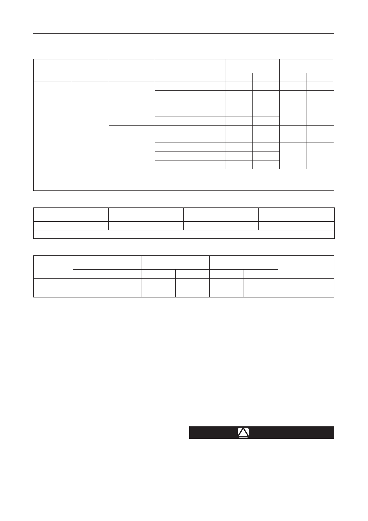
Table 1. Type LR125 Main Valve Body Sizes, End Connection Styles, Structural Design Ratings and
Maximum Operating Inlet Pressure
MAIN VALVE BODY SIZE
DN IN. bar psig bar psig
25, 50, 80
and 100
1. The pressure/t emperature lim its in this Instal lation Gu ide and any a pplic able st andard o r code li mitation shou ld not be exc eeded.
2. Ratin gs and end c onnec tions for other than ASME standard can usually b e provid ed. Cont act your local S ales Of ce for assist ance.
3. Maxi mum col d worki ng pres sure (CWP) p er ASME B16. 34 or pr oduct b ulletin limit, w hicheve r is lowes t. Temperatu re may dec rease these maximum pr essure.
4. Not available for 4 in. / DN 100 body size.
1, 2, 3
and 4
MAIN VALVE BODY
MATERIAL
WCC Steel
CF8M
Stainless steel
END CONNECTION STYLES
NPT or SWE (1 and 2 in. only) 103 1500 20.7 300
CL150 RF 20.0 290 20.0 290
CL300 RF 51.7 750
PN 16/25/40 RF
NPT (1 and 2 in. only) 99.2 1440 20.7 300
CL150 RF 19.0 275 19.0 275
CL300 RF 49.6 720
PN 16/25/40 RF
Table 2. Type MR95H Pilot Maximum Operating Pressure
BODY SIZE
1/2 NPT Steel or Stainless steel 20.7 bar / 300 psig 20.7 bar / 300 psig
1. The pressure/t emperature lim its in this Insta llatio n Guide and any appl icabl e standard or co de limit ation should no t be exceed ed.
BODY AND SPRING
CASE MATERIAL
MAXIMUM INLET PRESSURE MAXIMUM OUTLET PRESSURE
(1)
STRUCTURAL DESIGN
(2)
(4)
(4)
40.0 580
40.0 580
RATING
(1)
(3)
MAXIMUM OPERATING
INLET PRESSURE
20.7 300CL600 RF 103 1500
20.7 300CL600 RF 99.2 1440
(3)
Table 3. Outlet (Control) Pressure Ranges
SPRING WIRE
DIAMETER
5.26
5.94
7.19
PILOT
Type MR95H
OUTLET PRESSURE RANGE
bar psig mm In. mm In.
1.0 to 2.1
1.7 to 5.2
4.8 to 10.3
15 to 30
25 to 75
70 to 150
Overpressure Protection
The recommended pressure limitations are
stamped on the regulator nameplate. Some type of
overpressure protection is needed if the actual inlet
pressure exceeds the maximum operating outlet
pressure rating. Overpressure protection should
also be provided if the regulator inlet pressure
is greater than the safe working pressure of the
downstream equipment.
Regulator operation below the maximum pressure
limitations does not preclude the possibility of
damage from external sources or debris in the line.
The regulator should be inspected for damage after
any overpressure condition.
0.207
0.234
0.283
SPRING
FREE LENGTH
63.5
65.9
62.0
2.50
2.60
2.44
SPRING PART NUMBER
AND COLOR
1E395627022, Yellow
1D7455T0012, Green
1E395727192, Red
completed and relief valves properly adjusted,
slowly open the upstream and downstream
shutoff valves.
Adjustment
To change the outlet pressure, loosen the jam nut
and turn the adjusting screw clockwise to increase
outlet pressure or counterclockwise to decrease it.
Monitor the outlet pressure with a test gauge during
the adjustment. Tighten the jam nut to maintain the
desired setting.
Taking Out of Service (Shutdown)
Startup
The regulator is factory set at approximately
the midpoint of the spring range or the pressure
requested, so an initial adjustment may be required
to give the desired results. With proper installation
2
WARNING
!
To avoid personal injury resulting from
sudden release of pressure, isolate the
regulator from all pressure before
attempting disassembly.
 Loading...