

Emerson LR125 Instruction Manual
Instruction Manual
November 2014
Type LR125
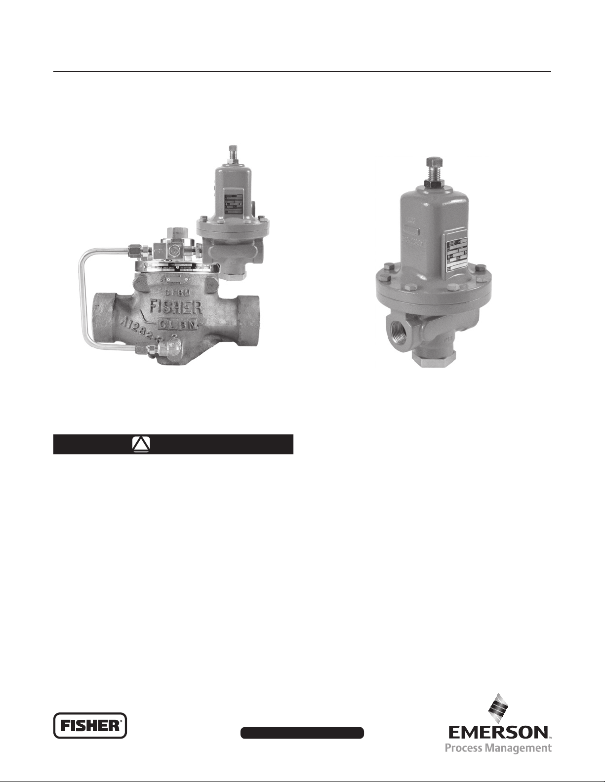
Type LR125 Pressure Reducing Liquid Regulator
TYPE LR125 REGULATOR
Figure 1. Type LR125 Pressure Reducing Liquid Regulator and Type MR95H Pilot
WARNING
!
Failure to follow these instructions or
to properly install and maintain this
equipment could result in bursting of the
equipment and/or chemical contamination
causing property damage and personal
injury or death.
Fisher® regulators must be installed,
operated and maintained in accordance
with federal, state and local codes, rules
and regulations and Emerson Process
Management Regulator Technologies, Inc.
(Emerson™) instructions.
If the regulator discharges process
uid or a leak develops in the system,
service to the unit may be required.
TYPE MR95H PILOT
Failure to correct trouble could result in a
hazardous condition.
Call a quali ed service person to service
the unit. Installation, operation and
maintenance procedures performed
by unquali ed personnel may result
in improper adjustment and unsafe
operation. Either condition may result in
equipment damage or personal injury.
Only a quali ed person must install or
service the regulator.
The Type LR125 is designed for liquid
service. Do not operate the regulator
in applications where temperatures are
below the process uid’s freezing point
or above its boiling point which are
dependent on the process uid and the
application pressures.
www.fisherregulators.com
D103576X012

Type LR125
Specications
Specications for the Type LR125 regulator are shown below. Other information for the main valve appears on the
nameplate. The control spring range for the pilot is marked on the nameplate of Type MR95H pilot.
Main Valve Body Sizes, End Connection Styles
and Structural Design Ratings
(1)
See Table 1
Maximum Inlet Pressures
Type LR125 Main Valve: See Table 1
(1)
Type MR95H Pilot: See Table 2
Type 112 Restrictor: 1500 psig / 103 bar
Outlet (Control) Pressure Ranges
See Table 3
Type LR125 Main Valve (continued)
Cage: Stainless steel
Spring: Stainless steel
Top Plug: Stainless steel
Bottom Plug: Stainless steel
Internal Inlet Strainer: Stainless steel
Diaphragm: Nitrile (NBR) or Fluorocarbon (FKM)
O-rings: Nitrile (NBR) or Fluorocarbon (FKM)
Flanged Locknut: Stainless steel
Backup Rings: Polytetrauoroethylene (PTFE)
Upper Spring Seat: Stainless steel
Main Valve Plug Travel
1 in. / DN 25: 0.37 in. / 9.4 mm
2 in. / DN 50: 0.68 in. / 17 mm
3 in. / DN 80: 0.98 in. / 25 mm
4 in. / DN 100: 1.19 in. / 30 mm
Main Valve Minimum Differential Pressures
(1)
See Table 5
Main Valve Internal Inlet Strainer Sizes
1 in. / DN 25:
12 Mesh (0.0661 in. / 1.68 mm)
(2)
2, 3 and 4 in. / DN 50, 80 and 100:
10 Mesh (0.0787 in. / 2 mm)
Temperature Capabilities
(2)
(1)
See Table 4
Pressure Registration
External: 1/2 NPT
Spring Case Vent
Type Y602-12
Construction Materials
Type LR125 Main Valve
Body: WCC Steel, CF8M or CF3M Stainless steel
Bonnet: LF2 Steel or 316/316L Stainless steel
Indicator Protector and Cover: Plastic
Indicator Stem: Stainless steel
Indicator Fitting: Stainless steel
Travel Indicator Plug: Stainless steel
Type MR95H Pilot
Body: WCC Steel or CF8M Stainless steel
Spring Case: WCC Steel or CF8M Stainless steel
Orice: Stainless steel
Diaphragm: Neoprene (CR) or Fluorocarbon (FKM)
Disk: Nitrile (NBR) or Fluorocarbon (FKM)
Mounting Parts
Pilot Mounting Pipe Nipple: Plated steel or
Stainless steel
Pipe Fittings: Plated steel or Stainless steel
Tubing: Stainless steel
Type 112 Restrictor
Body: 15-5 Stainless steel
Groove Valve: Stainless steel
Retainer: Stainless steel
Pipe Plug: Stainless steel
O-rings: Nitrile (NBR) or Fluorocarbon (FKM)
Options
• Pre-piped Pilot Supply
• Travel Indicator
Bonnet Bushing: Stainless steel
1. The pressure/temperature limits in this Instruction Manual and any applicable standard or code limitation should not be exceeded.
2. Nominal sieve opening
Introduction
Scope of the Manual
This instruction manual provides installation, startup,
adjustment, maintenance and parts ordering information
for Type LR125 pressure reducing regulator, 1/2 NPT
Type MR95H pilot and Type 112 restrictor.
2
Product Description
The Type LR125 pilot-operated, pressure reducing
regulator is used for liquid applications and include a
Type 112 restrictor and a 1/2 NPT Type MR95H pilot.
Pilot Type Description
Type MR95H — Pressure reducing pilot for 15 to
150 psig / 1.0 to 10.3 bar outlet pressures. Designed
to handle inlet pressures up to 300 psig / 20.7 bar.
Type LR125
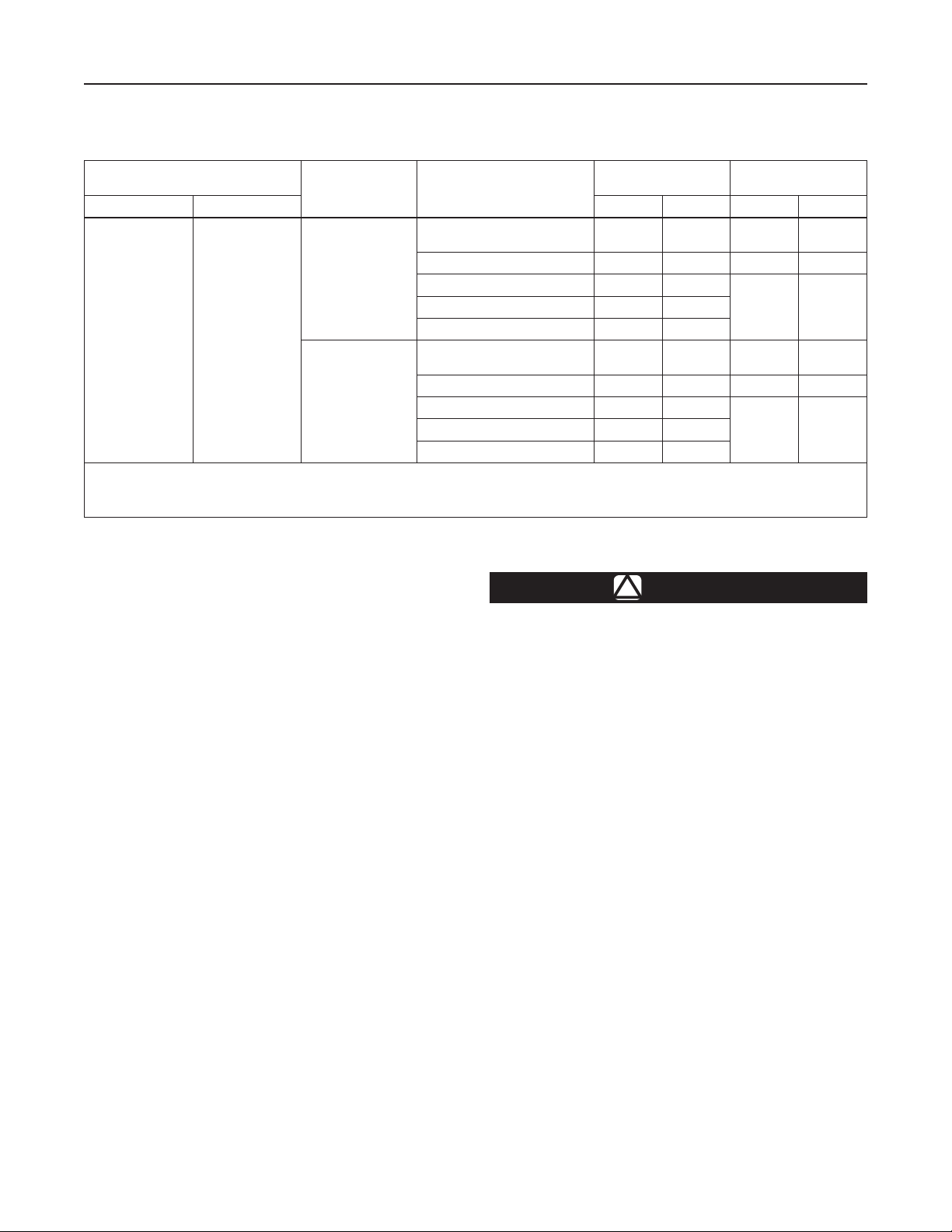
Table 1. Type LR125 Main Valve Body Sizes, End Connection Styles, Structural Design Ratings
and Maximum Operating Inlet Pressures
MAIN VALVE BODY SIZES
In. DN psig bar psig bar
1, 2, 3 and 4 25, 50, 80 and 100
1. The pressure/temperature limits in this Instruction Manual and any applicable standard or code limitation should not be exceeded.
2. Ratings and end connections for other than ASME standard can usually be provided. Contact your local Sales Ofce for assistance.
3. Maximum cold working pressure (CWP) per ASME B16.34 or product bulletin limit, whichever is lowest. Temperature may decrease these maximum pressures.
4. Not available for 4 in. / DN 100 body size.
Principle of Operation
MAIN VALVE BODY
MATERIAL
WCC Steel
CF8M Stainless
Steel
END CONNECTION STYLES
NPT or SWE
(1 and 2 in. only)
CL150 RF 290 20.0 290 20.0
CL300 RF 750 51.7
PN 16/25/40 RF
(1 and 2 in. only)
CL150 RF 275 19.0 275 19.0
CL300 RF 720 49.6
PN 16/25/40 RF
(4)
NPT
(4)
Type LR125 Installation
(1)
STRUCTURAL DESIGN
(2)
1500 103 300 20.7
580 40.0
1440 99.2 300 20.7
580 40.0
RATING
(3)
MAXIMUM OPERATING
INLET PRESSURE
300 20.7CL600 RF 1500 103
300 20.7CL600 RF 1440 99.2
(3)
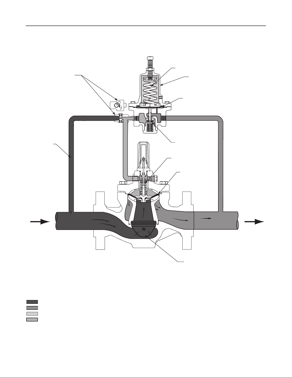
As long as the outlet (control) pressure is above
the outlet pressure setting, the pilot valve plug or
disk remains closed (Figure 2). Force from the main
spring, in addition to inlet pressure bleeding through
the restrictor, provide downward loading pressure to
keep the main valve diaphragm and plug assembly
tightly shutoff.
When the outlet pressure decreases below the pilot
outlet pressure setting, the pilot plug or disk assembly
opens. Loading pressure bleeds downstream through
the pilot faster than it can be replaced through the
supply line. This reduces loading pressure on top of
the main valve diaphragm and plug assembly and
lets the unbalanced force between inlet and loading
pressure overcome the main spring force to open the
Type LR125 diaphragm and plug assembly.
As the outlet pressure rises toward the outlet pressure
setting, it compresses the pilot diaphragm against
the pilot control spring and lets the pilot valve plug
or disk close. Loading pressure begins building on
the Type LR125 diaphragm and plug assembly. The
loading pressure, along with force from the main
spring, pushes the diaphragm and plug assembly onto
the tapered-edge seat, producing tight shutoff.
WARNING
!
Personal injury, equipment damage or
leakage due to escaping process uid
or bursting of pressure-containing
parts may result if this regulator is
overpressured or is installed where
service conditions could exceed
the limits given in Specications
section or where conditions exceed
any ratings of the adjacent piping or
piping connections.
To avoid such injury or damage, provide
pressure-relieving or pressure-limiting
devices (as required by the appropriate
code, regulation or standard) to prevent
service conditions from exceeding limits.
Additionally, physical damage to the
regulator could break the pilot off the
main valve, causing personal injury
and property damage due to escaping
process uid. To avoid such injury
and damage, install the regulator in a
safe location.
3
Type LR125
TYPE 112 RESTRICTOR
CONTROL SPRING
TYPE MR95H PILOT
DIAPHRAGM
SUPPLY
LINE
VALVE PLUG
MAIN SPRING
DIAPHRAGM AND
PLUG ASSEMBLY
INTERNAL STRAINER
M1215
INLET PRESSURE
OUTLET PRESSURE
ATMOSPHERIC PRESSURE
LOADING PRESSURE
4
Figure 2. Type LR125 Operational Schematic
Type LR125
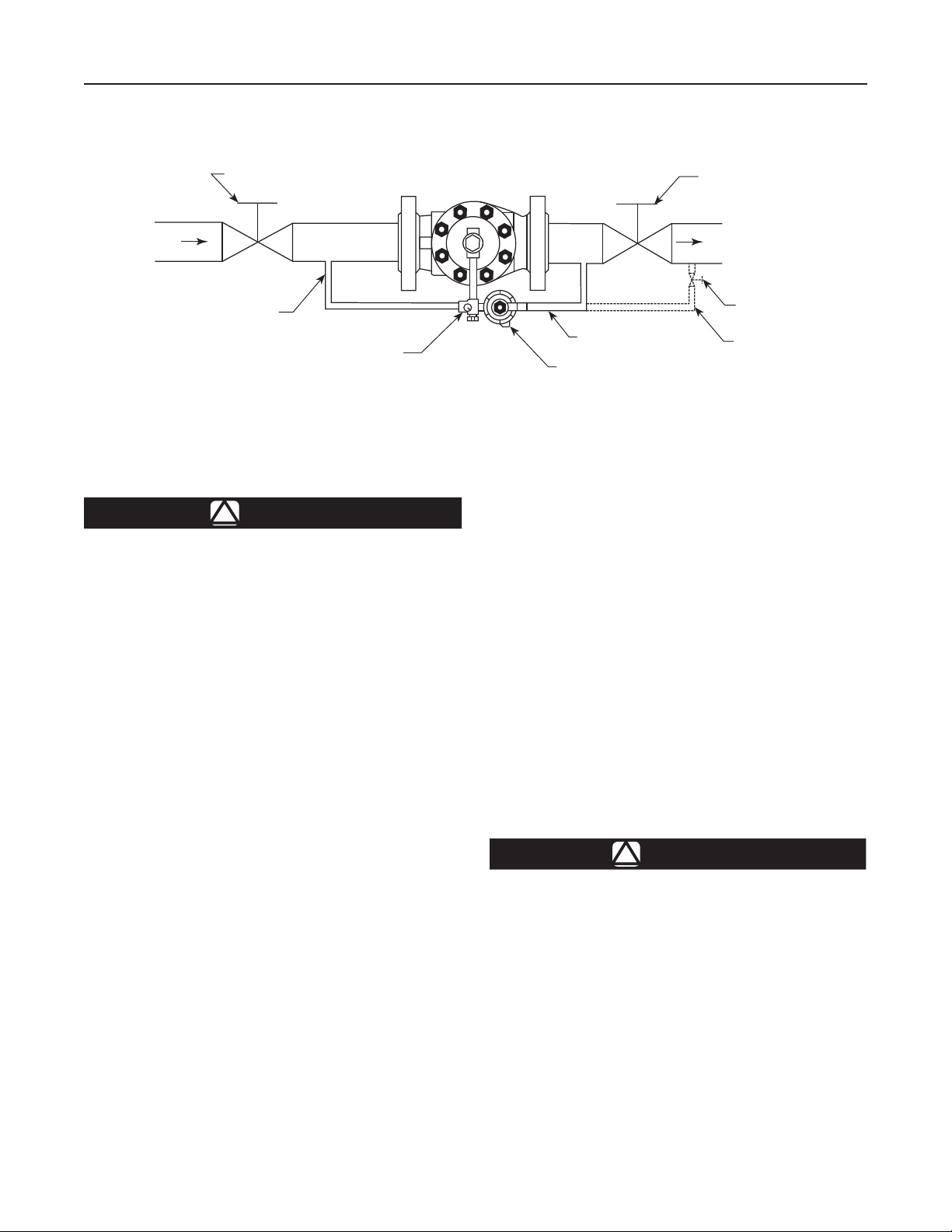
BLOCK VALVE
INLET
SUPPLY PRESSURE LINE
B2605_A
TYPE MR95H PILOT INSTALLATION WITH PILOT EXHAUST INTO CONTROL LINE
WARNING
!
RESTRICTOR
Figure 3. Typical Type LR125 Installation Schematic
Liquid pressure control systems should
be designed using engineering practices
to eliminate quick control starting or
stopping of the ow stream, which can
produce water hammer.
The robust design of the Type LR125 allows this
regulator to be installed indoors or outdoors. This
regulator is designed to withstand the elements.
The powder paint coating protects against minor
impacts, abrasions and corrosion. When installed
outdoors, the Type LR125 does not require protective
housing. However, the Type MR95H pilot should be
oriented so that the pilot spring case vent is pointed
down. Otherwise, make sure the vent is protected
so that rain, moisture, insects or any debris will not
accumulate inside or block the vent assembly.
When installed indoors, no remote venting is required
except on the pilot spring case. Refer to Step 5 of the
following procedure for the correct venting practices.
1. Only personnel quali ed through training and
experience should install, operate and maintain a
regulator. Before installation, make sure that there
is no damage to or debris in the regulator. Also,
make sure that all tubing and piping are clean
and unobstructed.
BLOCK VALVE
OUTLET
HAND VALVE
CONTROL LINE
TYPE MR95H PILOT
ALTERNATE CONTROL LINE
Note
The Type LR125 internal inlet strainer
is intended to prevent occasional
large particles from entering the main
valve. If the owing media contains
continuous particles, upstream ltration
is recommended before the main
valve and in the pilot supply piping.
See the Speci cations section for the
corresponding mesh size of the internal
inlet strainer.
2. A Type LR125 regulator may be installed in any
orientation, as long as ow through the regulator
matches the direction of the arrow on the main
valve body and the pilot vent is pointed down.
However, for easier maintenance, install the
regulator with the bonnet up.
CAUTION
Provide adequate support to the bonnet
when disassembling Type LR125
pressure reducing regulator installed in
a vertical installation or other application
where the bonnet is not oriented upward.
Without adequate support, the bonnet
may fall and cause physical injury when
the cap screws are loosened.
3. The standard pilot mounting position is as shown in
Figure 1. Other mounting positions are available.
5
Type LR125
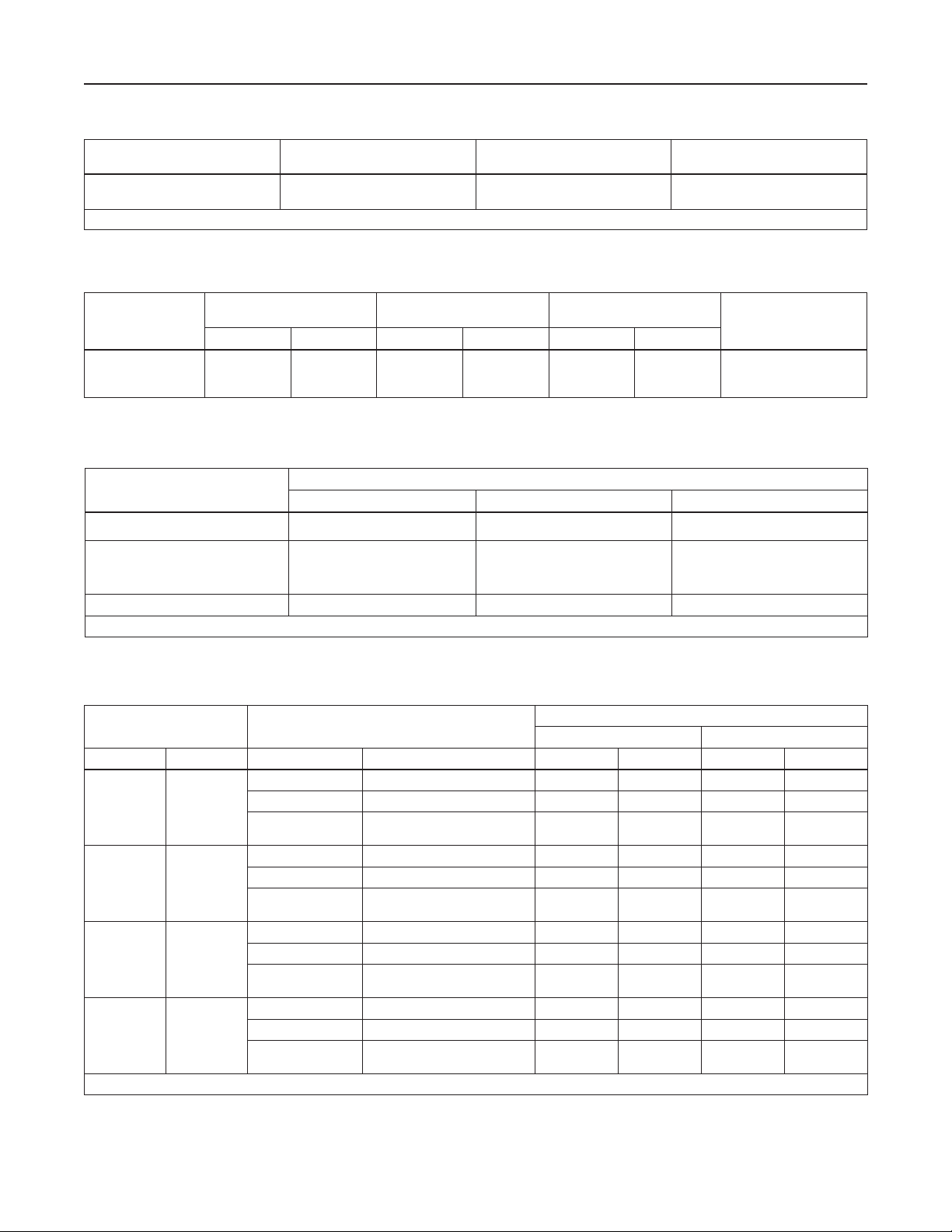
Table 2. Type MR95H Pilot Maximum Operating Pressures
BODY SIZE
1/2 NPT
1. The pressure/temperature limits in this manual, and any applicable standard or code limitation should not be exceeded.
BODY AND SPRING
CASE MATERIAL
Steel
Stainless Steel
MAXIMUM INLET PRESSURE MAXIMUM OUTLET PRESSURE
300 psig / 20.7 bar 300 psig / 20.7 bar
(1)
Table 3. Outlet (Control) Pressure Ranges
PILOT
Type MR95H
OUTLET PRESSURE RANGE
SPRING WIRE
DIAMETER
psig bar In. mm In. mm
15 to 30
25 to 75
70 to 150
1.0 to 2.1
1.7 to 5.2
4.8 to 10.3
0.207
0.234
0.283
5.26
5.94
7.19
SPRING
FREE LENGTH
2.50
2.60
2.44
63.5
65.9
62.0
SPRING PART NUMBER
AND COLOR
1E395627022, Yellow
1D7455T0012, Green
1E395727192, Red
Table 4. Diaphragm Material Selection Information
CRITERIA
17E68 Nitrile (NBR) (Standard) 17E97 Nitrile (NBR) 17E88 Fluorocarbon (FKM)
Liquid Temperature -20 to 150°F / -29 to 66°C 0 to 150°F / -18 to 66°C 0 to 250°F / -18 to 121°C
Best for low pressure differential
General Applications
service or cold temperature
applications
Heavy Particle Erosion Fair Excellent Good
1. Fluorocarbon (FKM) is limited to 200°F / 93°C in hot water.
DIAPHRAGM MATERIAL
Best for abrasive or erosive service
applications
Best for high temperature applications
(1)
Table 5. Main Valve Minimum Differential Pressures
MAIN VALVE BODY SIZE DIAPHRAGM
In. DN Diaphragm Code Diaphragm Material psid bar d psid bar d
17E68 (Standard) Nitrile (NBR), Low Minimum Differential 30 2.1 30 2.1
1 25
2 50
3 80
4 100
1. See Table 1 for Type LR125 main valve structural design ratings and Table 2 for Type MR95H pilot rating.
17E97 Nitrile (NBR), High Erosion Resistance 35 2.5 35 2.5
17E88
17E68 (Standard) Nitrile (NBR), Low Minimum Differential 18 1.2 19 1.3
17E97 Nitrile (NBR), High Erosion Resistance 24 1.7 24 1.7
17E88
17E68 (Standard) Nitrile (NBR), Low Minimum Differential 21 1.5 28 1.9
17E97 Nitrile (NBR), High Erosion Resistance 23 1.6 23 1.6
17E88
17E68 (Standard) Nitrile (NBR), Low Minimum Differential 16 1.1 30 2.1
17E97 Nitrile (NBR), High Erosion Resistance 16 1.1 34 2.3
17E88
Fluorocarbon (FKM),
High Temperature Capability
Fluorocarbon (FKM),
High Temperature Capability
Fluorocarbon (FKM),
High Temperature Capability
Fluorocarbon (FKM),
High Temperature Capability
30 2.1 30 2.1
18 1.2 19 1.3
21 1.5 28 1.9
16 1.1 30 2.1
(1)
MINIMUM DIFFERENTIAL, PERCENT OF CAPACITY
For 90% Capacity For 100% Capacity
6

Type LR125
4. Apply a good grade of pipe compound to the
external pipeline threads for a threaded body,
or use suitable line gaskets for a anged body.
Use approved piping procedures when installing
the regulator.
CAUTION
A regulator may leak toxic chemical to
the environment. In toxic or hazardous
liquid service, leaked chemical may
accumulate and cause personal injury,
death or property damage due to
escaping uid.
To prevent such injury or damage,
provide piping or tubing to vent the
hazardous liquid to a remote, safe
location away from air intakes or any
hazard-prone location. The exhaust
piping must be designed and installed to
guard against excessive ow restriction.
Protect the vent line or stack opening
against condensation or clogging.
5. If system operation during maintenance is required,
install isolating and vent valves as needed.
6. A clogged pilot spring case vent may cause
the regulator to function improperly. To prevent
plugging (and to keep the spring case from
collecting moisture, corrosive chemicals or other
foreign material) point the vent down, orient it to
the lowest possible point on the spring case or
otherwise protect it. Protect the vent assembly
from icing, moisture or debris that may cause
blockage, as required. Inspect the vent regularly
to make sure it has not been plugged. To remotely
vent a spring case, remove the vent and install
obstruction-free tubing or piping into the 1/4 NPT
vent tapping. Provide protection on a remote vent
by installing a screened vent cap onto the remote
end of the vent pipe.
7. As shown in Figure 3, run a supply pressure line
from the upstream pipeline to the restrictor inlet
(use 3/8 NPT outer diameter tubing or larger).
Install a lter or strainer upstream of the restrictor,
if needed, to keep the supply source from clogging
the restrictor or pilot. Inspect and clean this lter
regularly to make sure it has not been plugged
which can prevent proper regulator operation.
8. Install a downstream pressure control line with
a minimum size of 1/2 in. / 13 mm (as shown
in Figure 3) to the pilot control line or outlet
connection. Connect the other end of the control
line at a minimum of 8 to 10 pipe diameters
downstream of the regulator in a straight run of
pipe. Do not place a control line connection in a
turbulent area, such as in or directly downstream
of a swage or elbow. Signicant restrictions in
the control line can prevent proper pressure
registration. When using a hand valve, it should be
a full ow valve, such as a full port ball valve.
9. Good piping practices usually require swaging up
to larger downstream piping to obtain reasonable
downstream uid velocity.
Startup and Adjustment
Note
Tables 1 and 2 show the maximum inlet
pressures for specic constructions.
Use pressure gauges to monitor inlet
pressure, outlet pressure and any
intermediate pressure during startup.
Startup
1. Make sure all block and vent valves are closed.
2. Back out the pilot adjusting screw.
3. Set the restrictor to the “4” position.
4. SLOWLY OPEN the valves in the following order:
a. Pilot supply and control line valve(s), if used
b. Inlet block valve
c. Outlet block valve
5. Set the pilot to the desired outlet (control) pressure
according to the pilot adjustment procedure.
Pilot Adjustment
The factory setting of the regulator can be varied
within the pressure range stamped on the nameplate.
To change the outlet pressure, loosen the jam nut
(key 17, Figure 15) and turn the adjusting screw
(key 15) clockwise to increase outlet pressure or
counterclockwise to decrease it. Monitor the outlet
pressure with a test gauge during the adjustment.
Tighten the locknut to maintain the desired setting.
All regulator springs can be backed off to provide zero
outlet. Recommended outlet pressure ranges available
and color codes of the respective springs are shown
in Table 3.
7
Type LR125
Regulator Performance 2 4 6 8
Accuracy
Hysteresis
Stability
Speed of Response (Demand Decrease)
Speed of Response (Demand Increase)
Increased Performance Decreased Performance
Regulator Performance
2 4 6 8
Accuracy
Hysteresis
Stability
Speed of Response (Demand Decrease)
Speed of Response (Demand Increase)
Increased Performance Decreased Performance
Regulator Performance
2 4 6 8
Accuracy
Hysteresis
Stability
Speed of Response (Demand Decrease)
Speed of Response (Demand Increase)
Increased Performance Decreased Performance
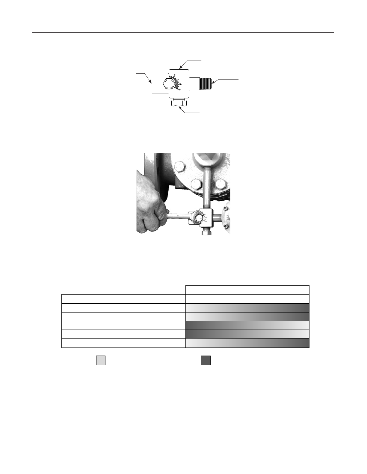
112 Restrictor Adjustment Guide
112 Restrictor Adjustment Guide
112 Restrictor Adjustment Guide
PILOT SUPPLY CONNECTION: 1/4 NPT PIPE
CONNECTS TO UPSTREAM PILOT SUPPLY TAP
LOADING CONNECTION: 1/4 NPT PIPE CONNECTS TO
TYPE LR125 DIAPHRAGM LOADING PORT
OUTLET CONNECTION: 1/4 NPT PIPE
CONNECTS TO PILOT INLET CONNECTION
11B5004-A
OPTIONAL LOADING CONNECTION:
1/4 NPT NORMALLY PLUGGED
Figure 4. Type 112 Restrictor
W4559_1
RESTRICTOR ADJUSTMENT
REGULATOR PERFORMANCE 2 4 6 8
Accuracy
Hysteresis
Stability
Speed of Response (Demand Decrease)
Speed of Response (Demand Increase)
TYPE 112 RESTRICTOR SETTING
Increased Performance
RESTRICTOR ADJUSTMENT GUIDE
Figure 5. Restrictor Adjustment
8
Decreased Performance
 Loading...