

Page 1
Product Bulletin
2052 Actuator
D103295X012
November 2014
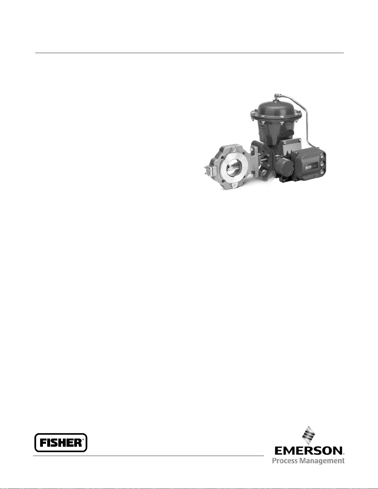
Fisherr 2052 Diaphragm Rotary Actuator
Fisher 2052 spring-and-diaphragm rotary actuators are
used on rotary-shaft valve bodies for throttling or
on-off applications. The 2052 may be used for
throttling service with a positioner, or it may be used
for on-off service without a positioner. The 2052 has an
ISO 5211 mating interface that allows installation to
non-Fisher valves. Refer to separate bulletins for valve
and positioner information.
Features
61.1:2052
n Compact design, smaller actuators-- Ensures
reduced valve/actuator envelope dimensions
leading to greater mounting versatility for both
skids and process plants, where space is at a
premium.
n Compatible with DVC2000, DVC6200, and
DVC6000 digital valve controllers; and 3610J and
3620J positioners-- The new actuator allows
linkage-less feedback, via a contact-less magnetic
array, from the lever to the end-mounted DVC2000.
Integral window mounting of the DVC6200,
DVC6000, 3610J, and 3620J is also available.
n Clamped lever to reduce lost motion-- The clamping
of the lever onto a splined valve shaft, coupled with
the single pivot linkage, reduces lost motion
between the actuator and the valve. The typical
cumulative deadband for a Fisher rotary control
valve assembly results in 0.5% or less variability.
n No bench set required-- The new nested spring
design requires no bench set. This also simplifies the
actuator selection process, see table 3.
n ISO 5211 mounting with optional insert-- The
actuator can now be mounted directly onto
non-spline shafts, such as Square and Double D. This
allows the actuator, with its enhanced control, to
mount on a wider range of valves conforming to ISO
5211.
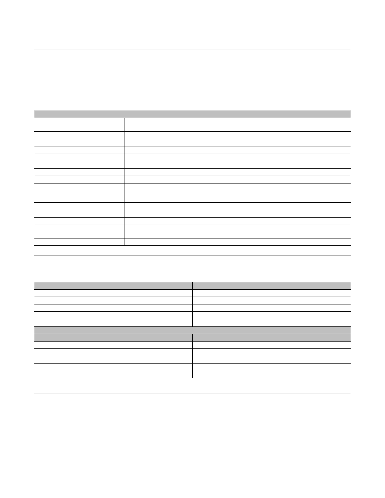
W9418-2
Fisher Control-Diskt Valve with 2052 Actuator and
FIELDVUE™ DVC6200 Digital Valve Controller
n Adjustable travel stops standard-- Provides the
ability to adjust or change the travel range by 30
degrees in either direction without removing the
actuator or the addition of extra parts.
n Fail-safe mechanism contains no aluminum-- All
parts in the fail-safe mechanism (made of steel, cast
iron, and ductile iron) ensure the actuator will
maintain safety integrity in the event of a fire.
n Powder paint as standard-- The Emerson Process
Managementt powder paint finish offers an
excellent corrosion-resistant finish to all external
steel and cast iron parts.
n NAMUR VDE/VDI 3845 bolt pattern for accessory
mounting-- Meeting the global standard ensures
compatibility for most accessories, enabling quick
and easy mounting.
n Field reversible, right- or left-hand mounting-- The
actuator/valve assembly action can be converted
from push-down-to-open to push-down-to-close, or
vice-versa, without additional parts.
n Declutchable and top-mounted handwheels--
Available for all sizes.
www.Fisher.com
Page 2
Product Bulletin
61.1:2052
November 2014
2052 Actuator Specifications and Materials of
Construction
See tables 1 and 2.
Table 1. Fisher 2052 Actuator Specifications
Specifications
Actuator Mounting Connections
Actuator Sizes See table 3
Operating Pressure
Maximum Diaphragm Casing Pressure Size 1, 2, and 3 Actuators: 5 barg (73 psig)
Pressure Connection See table 4
Torque Output See table 5
Actuator Temperature Capabilities
Operation Field reversible between PDTC and PDTO; right- and left-hand mounting, any angle of orientation
Approximate Weight
Controller/Positioners Available DVC2000, DVC6020, DVC6030, DVC6200, 3610J, 3620J, 4190, C1
Adjustable Travel Stops Standard adjustable up and down stops capable of 30 degrees of adjustment per stop.
Accessories Available 846, 646, 2625, and 67C Series, switches, i2P-100, VBL, DXP, GOt
Handwheel
Operational Lockout
1. The pressure/temperature limits in this bulletin should not be exceeded.
2. Lockout and declutchable handwheel cannot be used together on size 2 and size 3 actuators.
(1)
(1)
(2)
Splined shaft connection, ISO 5211 actuator-to-bracket connection
Top-mounted handwheel: Optional on Size 1, 2, and 3 actuators
Declutchable handwheel
Available for customer-supplied padlock to lock the actuator in the spring-fail position
Size 1: F07, Size 2: F10, Size 3: F14
See table 5
-45 to 80_C (-50 to 176_F)
Size 1: 22.2 kg (49 lb)
Size 2: 54.4 kg (120 lb)
Size 3: 113 kg (250 lb)
(2)
: Optional on Size 1, 2, and 3 actuators
2052 Actuator
D103295X012
Table 2. Materials of Construction
Component Material
Top Casing Steel
Housing Cast Iron
Diaphragm Nitrile and nylon standard
Lever Ductile iron
Diaphragm Plate Cast iron
OPTIONAL TOP-MOUNTED HANDWHEEL ASSEMBLY
Component Material
Handwheel Cast iron
Handwheel Stem Aluminum-Bronze
Top Casing Assembly Steel
O-ring Nitrile
Pusher Plate Steel
Contents
Features 1.....................................
2052 Actuator Specifications and Materials
of Construction 2............................
Options 3.....................................
Tables
Actuator and Shaft Size Availability 4.............
Torque versus Actuator Size 5...................
Pressure Connections 5........................
Dimensions 5.................................
Mounting Style 10.............................
2
Page 3
2052 Actuator
D103295X012
Product Bulletin
61.1:2052
November 2014
Options
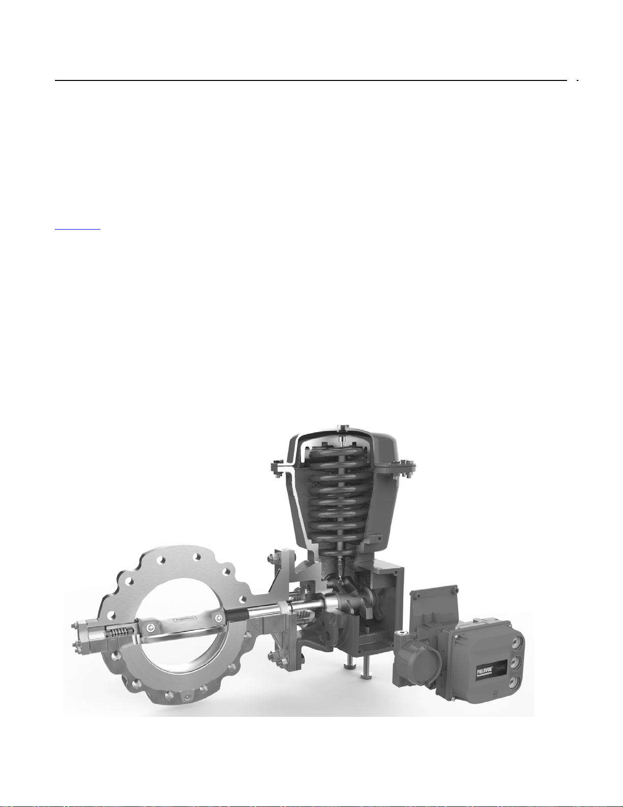
Top-Mounted Handwheel: For infrequent use as a
manual actuator (see figure 2). For repeated or daily
manual operation, the unit should be equipped with a
declutchable handwheel actuator.
Declutchable Handwheel Actuator: An end-mounted
manual actuator can be used to provide on-site control
and to provide override capabilities. See bulletin
61.8:1078
declutchable handwheel is not compatible with the
lockout option on the size 2 and size 3 actuators.
Limit Switches:
for one or two single-pole, double-throw contacts, or
J GO proximity switches for one or two single-pole,
double-throw contacts are available. See separate
bulletins for limit switch information.
Position Indicating Switch: TopWorxt DXP M21GNEB
switch for one through six single pole, double throw
switch contacts are available. See separate bulletin for
position indicating switch information.
Figure 1. Fisher 2052 Assembly
for handwheel actuator specifications. The
J Micro-Switch or NAMCO switches
Positioner: For precise positioning of the valve control
element, the actuator should be equipped with a
positioner. For additional information, contact your
Emerson Process Management sales office with
complete service conditions.
Optional Lockout Option: An actuator locking
mechanism is available, which can be used to keep the
actuator in a locked position (the same as the
spring-fail position) during maintenance. The padlock
is customer supplied. The lockout option on the size 2
and size 3 actuators is not compatible with the
declutchable handwheel.
Cold Service Construction: For services with ambient
temperatures down to -60_C (-76_F). This
construction is suitable for cold climate regions per
GOST 15150. Contact your Emerson Process
Management sales office for details. Note that the
current SIL certification for the 2052 actuator is only
relevant for the standard temperature ratings shown in
table 1. Not available with the top-mounted
handwheel option.
3
Page 4
Product Bulletin
61.1:2052
November 2014
Figure 2. Top-Mounted Handwheel
2052 Actuator
D103295X012
W9484
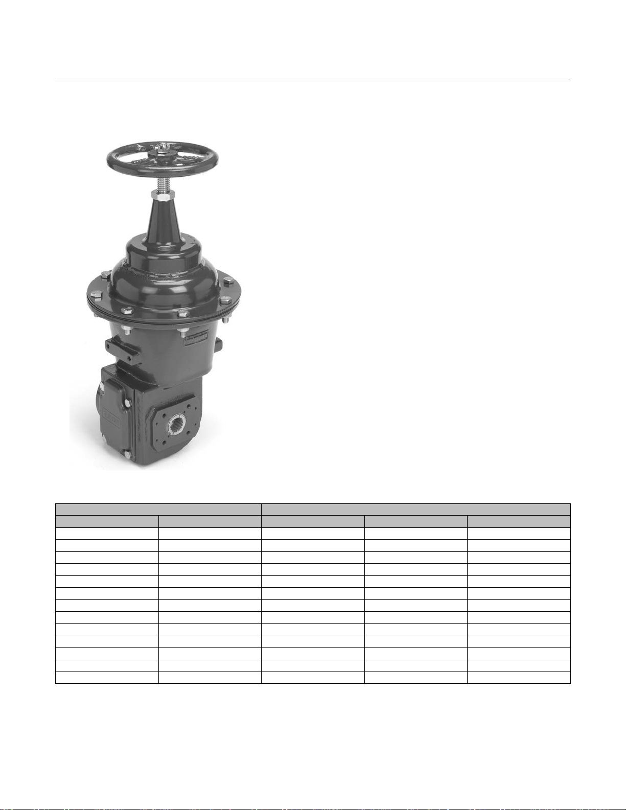
Table 3. Actuator and Shaft Size Availability
SHAFT SIZE ACTUATOR SIZE
mm Inches 1 2 3
12.7 1/2 X
14.3 x 15.9 9/16 x 5/8 X X
15.9 5/8 X X
19.1 3/4 X X X
22.2 7/8 X X
25.4 1 X X
28.6 x 31.8 1-1/8 x 1-1/4 X X
31.8 1-1/4 X X
31.8 x 38.1 1-1/4 x 1-1/2 X
38.1 1-1/2 X
39.7 x 44.5 1-9/16 x 1-3/4 X
44.5 1-3/4 X
50.8 2 X
4
Page 5

Product Bulletin
2052 Actuator
D103295X012
Table 4. Pressure Connections
ACTUATOR
SIZE
1 standard optional not available optional
2 standard optional not available optional
3 not available standard optional not available
1/4 NPT 1/2 NPT 3/4 NPT G 1/4
PRESSURE CONNECTION
Table 5. Torque versus Actuator Size
ACTUATOR
SIZE AND
ACTION
1 (PDTO)
1 (PDTC)
2 (PDTO)
2 (PDTC)
3 (PDTO) 327 2890 327 2890 631 5580 631 5580
3 (PDTC) 280 2480 557 4930 584 5170 930 8230
1. Do not interpolate between operating pressures. Consult your Emerson Process Management sales office for assistance.
2 barg (29 psig)
NSm lbfSin NSm lbfSin NSm lbfSin NSm lbfSin
25.5
25.5
105
105
(1)
226
226
930
930
3 barg (44 psig)
25.5
36.2
105
175
OPERATING PRESSURE
(1)
Torque
226
320
930
1550
4 barg (58 psig)
51.2
51.2
210
210
(1)
453
453
1860
1860
November 2014
4.7 barg (68 psig)
51.2
72.4
210
320
61.1:2052
(1)
453
641
1860
2840
Table 6. Dimensions
ACTUATOR
SIZE
1 245 9.65 267 10.51 29 1.14 103 4.06 107 4.21 71 2.80
2 350 13.78 424 16.69 49 1.93 187 7.36 170 6.69 84.5 3.33
3 496 19.53 592 23.31 64 2.52 254 10.0 185 7.28 92 3.62
C E F H P Y
mm Inches mm Inches mm Inches mm Inches mm Inches mm Inches
Table 7. Actuator / Valve Body Mounting Dimensions
VALVE SHAFT DIAMETER
mm Inches mm Inches mm Inches mm Inches
Style F Mounting: Control-Disk, Vee-Ball™, 8532, 8510B, 8560, and 8580 Eccentric Disk Valves
12.7 - 15.9 1/2 - 5/8 A 117 4.62 - - - - - - 14.2 0.56
19.1 - 25.4 3/4 - 1 B 152 6.00 32 1.25 14.2 0.56
31.8 - 38.1 1-1/4 - 1-1/2 B 235 9.25 46 1.81 17.5 0.69
44.5 - 50.8 1-3/4 - 2 B 273 10.75 51 2.00 20.6 0.81
12.7 1/2 A 117 4.62 - - - - - - 11.0 0.44
15.9 - 25.4 5/8 - 1 B 146 5.75 32 1.25 11.0 0.44
31.8 - 38.1 1-1/4 - 1-1/2 B 210 8.25 51 2.00 17.5 0.69
FIGURE 6 REFERENCE
Style G Mounting: 9500 Series Valves
T U W
5
Page 6

Product Bulletin
61.1:2052
November 2014
Table 8. Actuator / Valve Body Mounting Dimensions
VALVE SHAFT DIAMETER
mm Inches mm Inches mm Inches mm Inches
12.7 1/2 135 5.3
15.9 5/8 135 5.3 148.5 5.8
19.1 3/4 158 6.2 171.5 6.8 179 7.0
25.4 1 171.5 6.8 179 7.0
31.8 1-1/4 169.5 6.7 177 7.0
38.1 1-1/2 177 7.0
44.5 1-3/4 316 12.4
50.8 2 316 12.4
Size 1 Size 2 Size 3
V
Table 9. Actuator / Valve Body Mounting Dimensions
ACTUATOR SIZE
1 207 8.1 171 6.7 1/4 NPT
2 289 11.4 305 12.0 1/4 NPT
3 398 15.67 356 14.0 1/2 NPT
mm Inches mm Inches NPT Connection Used
Hc Jc R
2052 Actuator
D103295X012
Table 10. NAMUR Instrument Mounting Dimensions
ACTUATOR SIZE
1 80 30 30.4 35
2 130 30 48.34 55
3 130 30 65 75
J K L N
mm mm mm mm
Table 11. ISO 5211 Mounting Information
ACTUATOR SIZE F SIZE
1 F07 70 M8 16.5
2 F10 102 M10 29.0
3 F14 140 M16 49.0
A B AA BB
mm mm mm mm
Table 12. ISO 5211 Square Insert Sizes Available
SQUARE SIZE ACTUATOR SIZE
mm 1 2 3
9 X
11 X X
14 X X X
19 X X
22 X X
27 X
36 X
See table 12
6
Page 7

2052 Actuator
D103295X012
Figure 3. Dimensions (also see tables 6, 7, and 8)
C DIAMETER
Product Bulletin
61.1:2052
November 2014
E
GG00138-A
H
F
P
Y
(Y)
V
7
Page 8

Product Bulletin
61.1:2052
November 2014
Figure 4. Handwheel Dimensions (also see tables 6 and 9)
Jc DIA
Hc
R
2052 Actuator
D103295X012
E
GE38370_1
Figure 5. Mounting Yokes Dimensions (also see table 7)
T
W DIA
GE38375_1
U
T
W DIA
REFERENCE A REFERENCE B
8
Page 9

2052 Actuator
D103295X012
Figure 6. NAMUR Instrument Mounting Dimensions (also see tables 10 and 11)
45_
Product Bulletin
61.1:2052
November 2014
2X M3
K
1
N
L
GG06029_B
N is the outside diameter of the lever hub.
1
J
Figure 7. ISO 5211 Square Lever Insert Dimensions (also see table 11)
4X M5
A
4X B
BB
AA
VIEW C-C
9
Page 10

Product Bulletin
61.1:2052
November 2014
Figure 8. Fisher 2052 Actuator Mounting Styles (also see table 13)
2052 Actuator
D103295X012
LEFT HAND MOUNTING
STYLE D SHOWN
STYLE D
4
2
3
POSITION 1
STANDARD
4
STYLE C
3
RIGHT HAND MOUNTING
VALVE
INLET
2
FLOW
VALVE
INLET
FLOW
STYLE A
4
STYLE B SHOWN
STYLE B
POSITION 1
STANDARD
2
3
4
2
3
GE37285-B
Table 13. Fisher 2052 Actuator Mounting Styles
MOUNTING
(SEE FIGURE
8)
RIGHT-HAND
LEFT-HAND
LEFT-HAND
(Optional)
1. PDTC = Push Down To Close. PDTO = Push Down To Open.
(1)
ACTION
PDTC CCW A A A CW NA B
PDTO CCW B B B CW NA A
PDTC CCW D D NA CW C C
PDTO CCW C C NA CW D D
PDTC CW C NA NA NA NA NA
PDTO CW D NA NA NA NA NA
Ball/Plug
Rotation to
Close
V150, V200,
V300 Series
CV500 and
V500
VALVE
V250
Ball/Plug
Rotation to
Close
V250
8510, 8510B,
8532, 8560,
8580, 9500,
Control-Disk
10
Page 11

2052 Actuator
D103295X012
Product Bulletin
61.1:2052
November 2014
11
Page 12

Product Bulletin
61.1:2052
November 2014
2052 Actuator
D103295X012
Neither Emerson, Emerson Process Management, nor any of their affiliated entities assumes responsibility for the selection, use or maintenance
of any product. Responsibility for proper selection, use, and maintenance of any product remains solely with the purchaser and end user.
Fisher, Control-Disk, FIELDVUE, GO, TopWorx, and Vee-Ball are marks owned by one of the companies in the Emerson Process Management business unit of
Emerson Electric Co. Emerson Process Management, Emerson, and the Emerson logo are trademarks and service marks of Emerson Electric Co. All other
marks are the property of their respective owners.
The contents of this publication are presented for informational purposes only, and while every effort has been made to ensure their accuracy, they are not
to be construed as warranties or guarantees, express or implied, regarding the products or services described herein or their use or applicability. All sales are
governed by our terms and conditions, which are available upon request. We reserve the right to modify or improve the designs or specifications of such
products at any time without notice.
Emerson Process Management
Marshalltown, Iowa 50158 USA
Sorocaba, 18087 Brazil
Chatham, Kent ME4 4QZ UK
Dubai, United Arab Emirates
Singapore 128461 Singapore
www.Fisher.com
E 2008, 2014 Fisher Controls International LLC. All rights reserved.
12
 Loading...