

Page 1
Slurry Vee-Ball Valve
D103154X012
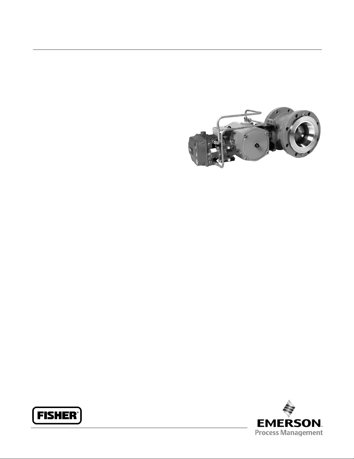
Fisherr V150S
Slurry Vee-Ball™ Control Valve
The Fisher V150S Slurry Vee-Ball valve mates with
CL150 raised face flanges. Rugged construction, highly
wear-resistant trim materials, and an unrestricted
straight through flow path make the design ideal for
controlling the most abrasive of slurries.
A shaft with a choice of drive connections will allow a
variety of power operated actuators and valve
positioners or controllers to be used.
W8512
The design is particularly effective in minimizing
erosive damage to the adjoining pipework, thereby
providing greater operational safety and service life
when compared with other valve types.
Features
Fully protective trim–The valve body, shaft, and
bearings are fully protected by hard wear-resistant
trim materials.
Pipeline and flange protection–The throttled flow
stream is guided through a specially shaped flow
ring to minimize turbulence and impingement on
thepipewall.Thevalvecanbematchedtothebore
size of the inlet and outlet piping in order to prevent
turbulence being generated by the step resulting in
scouring erosion of the flange faces, unexpected
leakage, and expensive rework. In addition, both
the inlet and outlet valve flange faces are protected
by a portion of the hard trim.
Fisher V150S Slurry Vee-Ball Control Valve
Long Service Life–The Vee-Ball design, when used in
reverse flow mode, keeps the high velocity down
stream of the vena contracta within the flow ring
bore at the outlet of the valve. Compared with other
styles of valves, the exit flow is essentially parallel
with the flow ring wall and a minimum of flow
impingement occurs. Combined with a choice of
hard wear-resistant materials, a significantly long
life is obtained.
Easily replaceable trim parts allow the valve to be
overhauled at predetermined intervals and the
valve body used again during repeated operational
cycles.
Ease of installation–Full flanging on the valve body
allows the valve body to be easily aligned c entrally
with the pipe flanges, an essential requirement in
avoiding erosion across the flange faces.
Excellent Flow Control–Precise contouring of the
V-notch ball provides a modified equal percentage
flow characteristic. When combined with a valve
actuator/controller system having minimal lost
motion, improved process control can be obtained.
Product Bulletin
51.3:V150S
February 2013
(continued on page 2)
www.Fisher.com
Page 2

Product Bulletin
51.3:V150S
February 2013
Slurry Vee-Ball Valve
D103154X012
Features (continued)
Quick and Easy Maintenance–All trim parts are
retained without the use of press fits or screw
threads exposed to the process fluid. See figure 1.
Structural Integrity–The valve body, complete with
flanges, is made from a one-piece casting. No
welding is employed. No O-ring seals are used. Use
of a flanged valve body does not require the use of
extra long studs.
The shaft seal is made from well-proven PTFE
chevron ring packing with the means for external
adjustment.
Options
A PSZ (partially stabilized zirconia) ceramic flow ring
insert is available with HCI (high chrome iron) or PSZ
ceramic ball for particularly aggressive slurry
services with extended lifetime requirements. The
ceramic insert offers substantial increase in flow
ring lifetimes.
Trim materials are available to meet the
requirements of corrosive/erosive slurries.
See table 2.
The“FlowOvertheTop”V-NotchBalloffersan
alternative to the standard V-Notch Ball in scaling
applications.
The drive shaft is available with either a double D or
splined actuator connection to accommodate a
choice of actuation between a spring-opposed
diaphragm or a rack and pinion.
2
Page 3

Slurry Vee-Ball Valve
D103154X012
Specifications
Product Bulletin
51.3:V150S
February 2013
Valve Sizes
J NPS 3, J 4, J 6, J 8, J 10, and J 12
End Connection
V150S: CL150 Raised-face flange
Face to Face Dimension
Seefigure2
Maximum Inlet Pressure
Consistent with pressure-temperature ratings per
ASME B16.34 but do not exceed the material
temperature capabilities shown below or the pressure
drop limitations
Maximum Shut Off Pressure
See tables 3 and 4
Shutoff Classification
Class I per ANSI/FCI 70-2 and IEC 60534-4
(Class II and better not available). A defined initial
maximum leak rate can be provided subject to review
of service conditions.
Construction Materials
Standard Construction: See table 1
Temperature Capability
For Trim 1: 427_C(801_F) maximum
For Trims 2 and 3: 230_C(446_F) maximum
For materials: See table 1
Flow Characteristic
Approximately equal percentage
Dimensions
See figures 2 and 3
Flow Direction
Reverse flow recommended (into concave face of
ball, out through the flow ring)
Flow Coefficients
See Fisher Catalog 12
Maximum Ball Rotation
90 degrees
Valve Installation
Shaft axis to be horizontal
Actuator Mounting
Right-hand or left-hand, as viewed from upstream
end of valve
Valve/Actuator Action
With diaphragm or piston rotary actuator and splined
shaft, the valve is field-reversible between PDTC or
PDTO:
rod closes valve) and
(extending actuator rod opens valve)
Actuator Size Selection
Contact your Emerson Process Management sales
office for information
Approximate Weight
NPS 3: 15 kg (33 lb)
NPS 4: 28 kg (62 lb)
NPS 6: 45 kg (99 lb)
NPS 8: 82 kg (180 lb)
NPS 10: 120kg(265lb)
NPS 12: 178kg(390lb)
J push-down-to-close (extending actuator
J push-down-to-open
3
Page 4

Product Bulletin
51.3:V150S
February 2013
Table 1. Standard Construction Materials
MATERIAL TEMPERATURE CAPABILITY
Part Material
Minimum Maximum Minimum Maximum
Valve Body Carbon Steel ASTM A216 WCC -29 427 -20 800
Body Liner High Chrome Iron ASTM A532 Class IIIType A -29 427 -20 800
V-Notch Ball
Flow Ring
Flow Ring Retainer Carbon Steel ASTM A105 -29 427 -20 800
Bearing Shroud High Chrome Iron ASTM A532 Class IIIType A -29 427 -20 800
Bearing S44004 58Rc -29 427 -20 800
Drive Shaft S17400 Cond.H1025 -29 427 -20 800
Follower Shaft S17400 Cond.H1025 -29 427 -20 800
Shaft Pins S42000 -29 427 -20 800
Gaskets Graphite SST Laminate -198 538 -325 1000
Packing Set
Packing Box Ring and Follower S31600 -198 538 -325 1000
Studs B8M Class 2 -45 538 -50 1000
Nuts S31600 -45 538 -50 1000
Retainer Screws and Clips S31600 -45 538 -50 1000
Spring S30400 -29 427 -20 800
Plug S31600 -45 538 -50 1000
High Chrome Iron ASTM A532 Class IIIType A -29 427 -20 800
PSZ Ceramic (optional) -29 427 -20 800
High Chrome Iron ASTM A532 Class IIIType A -29 427 -20 800
HCI with Ceramic Insert (optional) -29 230 -20 450
PTFE V-ring -46 230 -50 450
Graphite -198 538 -325 1000
_C _F
Slurry Vee-Ball Valve
D103154X012
Table 2. Trim Levels
Trim Level Ball Flow Ring Valve Body Liner Bearing Shrouds
1 (standard) HCI (High Chrome Iron) HCI HCI HCI
2 HCI HCI with ceramic insert HCI HCI
3 Ceramic Ball HCI with ceramic insert HCI HCI
4
Page 5

Slurry Vee-Ball Valve
D103154X012
Product Bulletin
51.3:V150S
February 2013
Table 3. Maximum Allowable Shutoff Pr essure Drops
(Valve Body Ratings) based on Carbon Steel Material.
Consult the tables for both trim and body limits.
TEMPERATURE
RANGE
_C Bar
-46 to-29 ---
-29 to 38 20.0
93 17.9
149 15.9
204 13.8
232 12.8
260 11.7
316 10.7
343 9.65
371 8.62
399 6.55
427 5.52
_F Psi
-50 to-20 ---
-20 to100 290
200 260
300 230
400 200
450 185
500 170
550 155
600 140
650 125
700 110
750 95
800 80
PRESSURE RATING
WCC CL150
Table 4. Maximum Allowable Shutoff Pressure Drops
based on Standard Trim.
Note: Do not exceed the pressure/temperature
rating of the valve or mating flanges
TEMPERATURE
RANGE
_C Bar
-29 to427 47.0 27.5 28.3 27.5 15.2 13.8
_F Psi
-20 to800 680 400 410 400 220 200
1. Refer totable 3.
3 4 6 8 10 12
VALVE SIZE, NPS
Figure 1. V150S Cutaway View
W9177
5
Page 6

Product Bulletin
51.3:V150S
February 2013
Slurry Vee-Ball Valve
D103154X012
Table 5. Fisher V150S Dimensions
VALVE SIZE
DN mm
80 165 80.0 235 140 130 104 98.0 19.1 152 31.8 14.2
100 194 102 214 152 140 117 98.0 19.1 152 31.8 14.2
150 230 111 214 175 164 124 112 25.4 152 31.8 14.2
200 304 184 208 220 231 195 124 31.8 235 46.0 17.5
250 385 235 208 250 261 235 132 31.8 235 46.0 17.5
300 455 291 208 300 304 270 132 38.1 235 46.0 17.5
NPS Inch
3 6.49 3.15 9.26 5.51 5.12 4.11 3.86 0.75 6.00 1.25 0.56
4 7.62 4.02 8.44 5.98 5.53 4.61 3.86 0.75 6.00 1.25 0.56
6 9.06 4.38 8.44 6.89 6.45 4.90 4.40 1.00 6.00 1.25 0.56
8 11.96 7.25 8.19 8.66 9.11 7.68 4.90 1.25 9.25 1.81 0.69
10 15.16 9.26 8.18 9.84 10.26 9.25 5.19 1.25 9.25 1.81 0.69
12 17.91 11.47 8.18 11.81 11.97 10.63 5.19 1.50 9.25 1.81 0.69
1. Stud length associated with clearance dimension “M”is longer than standard length specified in ASME B16.5.
2. Clearance necessary to removeflange bolts.
A B D G K M
V150S DIMENSIONS
(2)
(1)
(2)
N
SDiameter T U W
Figure 2. V150S Dimensions (see table 5)
SDIAMETER
U
E0875
T
W
B
A
MN
G K D
SIZE
3 THROUGH 12
6
Page 7

Slurry Vee-Ball Valve
D103154X012
Product Bulletin
51.3:V150S
February 2013
Table 6. Fisher V150S Dimensions for Double D Shaft
Drive
VALVE
SIZE
DN mm
80 83 19.0 25.4 14.2 95 25
100 83 19.0 25.4 14.2 95 25
150 83 25.4 25.4 17.5 95 25
200 83 31.8 25.4 20.6 133 38
250 89 31.8 25.4 20.6 133 38
300 89 38.1 38.1 25.4 133 38
NPS Inch
10 3.5 1.25 1.0 0.81 5.25 1.5 5/8-11
12 3.5 1.5 1.5 1.0 5.25 1.5 5/8-11
1. This nominal valve shaft diameteris the shaft d iameter through the packing box.
Use this diameter when selecting Fisher actuators.
E S
3 3.25 0.75 1.0 0.56 3.75 1.0 1/2-13
4 3.25 0.75 1.0 0.56 3.75 1.0 1/2-13
6 3.25 1 1.0 0.69 3.75 1.0 1/2-13
8 3.25 1.25 1.0 0.81 5.25 1.5 5/8-11
FLAT
(1)
LENGTH
FLAT
SIZE
T U W
see
below
Figure 3. V150S Dimensions for Double D Shaft Drive
(see table 6)
E
FLAT
LENGTH
38B2695-A
FLAT SIZE
S
T
W
U
7
Page 8

Product Bulletin
51.3:V150S
February 2013
Figure 4. Fisher V150S NPS 6 Valve
FLOW RING
FOLLOWER SHAFT
PLUG
Slurry Vee-Ball Valve
D103154X012
V-NOTCH BALL
FLOW RING RETAINER
GASKET
DRIVE SHAFT
SHAFT PIN
W8509
VALVE BODY
PACKING FOLLOWER
PACKING SET
BEARING
BEARING SHROUD
VALVE BODY LINER
Neither Emerson, Emerson Process Man agement, nor any of their affiliated entities assumes responsibility for the selection, use or maintenance
of anyproduct. Responsibility for proper selection, use, and maintenance of any product remains solelywith the purchaser and end user.
Fisher and Vee-Ball are marks owned by one of thecompanies in the Emerson Process Management business unit of Emerson Electric Co. Emerson Process
Management, Emerson, and the Emersonlogo are trademarks and service marksof EmersonElectric Co. All other marks are the property oftheir respective
owners.
The contents of this publication are presented for informational purposes only, and while every effort has been made to ensure their accuracy, they arenot
to be construed as warranties or guarantees, express or implied, regarding the products or services described herein or their use or applicability. All sales are
governed by our terms and conditions, which are availableupon request. We reserve the right to modify or improve the designs or specificationsof such
products at any time without notice.
Emerson Process Management
Marshalltown, Iowa 50158 USA
Sorocaba, 18087 Brazil
Chatham, Kent ME4 4QZ UK
Dubai, United Arab Emirates
Singapore 128461 Singapore
www.Fisher.com
E 2003, 2013 Fisher Controls International LLC. All rightsreserved.
8
 Loading...