

Page 1

Instruction Manual
MCK-1157
Types N480 and N481
October 1981
Types N480 and N481 Hose End Valves
WARNING
!
Install, use, and maintain per Fisher
instructions and all applicable federal,
state, laws and codes, and NFPA No. 58 or
Standards K61.1. Periodic inspection and
maintenance is essential.
Introduction
Types N480 and N481 hose end valves are intended
as quick-acting primary shutoff valves for the end of
the transfer hose on bobtail delivery trucks. Standard
valves can be used on propane, butane, and NH
3
service at ambient temperature. For other LP-gases
and compressed gases or other temperature conditions
consult the factory.
Type N480
—Includes a supplementary back check
assembly (Type M570) and is suitable for LP-gas
service only.
Type N481 —Without back check assembly, for use on
NH3 service only.
Installation
Apply suitable pipe compound to the 1-inch male pipe
threads of a hose coupling (Fisher Type M4100-16 or
equivalent). Screw the hose end valve on the hose
coupling using the wrenching flats on the valve’s inlet
connection. Use sufficient torque to make a tight seal
between the valve inlet and the hose coupling
.
The valve’s operating lever rests near the hose
connection when in the closed position. There must be
sufficient clearance between the operating lever and the
hose coupling to insure complete closure of the valve and
easy grasp of the operating lever.
Most hose couplings will work with the N480 or N481,
but if there is insufficient clearance, change the hose
coupling. If possible, store the hose end valve on the
delivery truck in a place protected from the elements.
Operation
When Type N480 or N481 is not connected to a
1 3/4-inch male Acme thread (such as a standard filler
connection), moving the operating lever to the open
position does not open the hose end valve, refer to view 3
1
LEVER CLOSED,
CONNECTED TO
FILLER VALVE
T40384
Figure 1. N480 Operational Schematic
in Figure 1. The valve must be attached to a male Acme
fitting, views 1 and 2 in Figure 1, before it will open.
Before attaching either the N480 or N481 to a filler valve,
make sure there is no dirt or other foreign material in
the top of the filler valve or in the hose end valve outlet.
Foreign material could be forced into the filler valve
causing damage and creating a hazardous malfunction.
Also make sure the hose end valve’s operating lever
the closed position, view 1 in Figure 1, before the valve
is attached to the filler valve. Otherwise the hose end
valve could open as it is threaded on to the filler valve.
As with many quick-acting valves, the
operating lever on the N480 or N481 can
snap closed with some force. Be careful
not to pinch a hand or fingers between the
operating lever and the body when closing
the valve.
!
As with any hose end valve, loosen
the connection on the filler valve slightly
to allow pressure to bleed off before
completely unscrewing the connection. If
pressure continues to bleed and does not
reduce, never unscrew the hose end valve
because either the filler valve or the hose
end valve has not shut off. Disconnecting
the hose end valve could permit the rapid
escape of gas.
2
LEVER OPEN,
CONNECTED TO
FILLER VALVE
CAUTION
WARNING
3
LEVER OPEN,
VALVE NOT
CONNECTED
is in
R
D450044T012
www.FISHERregulators.com/lp
Page 2
Types N480 and N481
Type N480 has a brass accessory back check
(Type M570) that can be tightened back onto filler valves
that fail to close. Then the N480 main valve can be
loosened from the back check. If the pressure bleeds
off between the N480 and the M570, the M570 can be
left on the filler valve until repairs can be made, and the
N480 main valve can be disconnected. Leave the M570
on a filler valve only until the tank can be emptied and
repair or replacement of the filler valve can be made.
If pressure does not bleed off between the N480 and
M570, there is still a problem. Do not disconnect until
the problem is corrected and the valves seal tightly. Try
quickly opening and closing the N480 or tapping the
sides of the valves to seat the check valves.
Should it be necessary to detach the M570 and leave
it on a ftiler valve, fit a new M570 to the N480 as soon
as possible. Do not use any model of back check
assembly other than the M570 because other models
could allow accidental opening of the N480 when
being carried.
Maintenance
Check the hose end valve periodically for signs of wear
or mechanical damage. The operating
should be kept free of obstructions. The surface of the
flow tube which seals against the filler valve’s gasket
should be kept free of large nicks. Check the coupler
for wear. If repair becomes necessary, contact a Fisher
distributor or the factory for information and assistance.
Do not use valves that leak or fail to operate correctly;
repairs should be made promptly.
lever and linkages
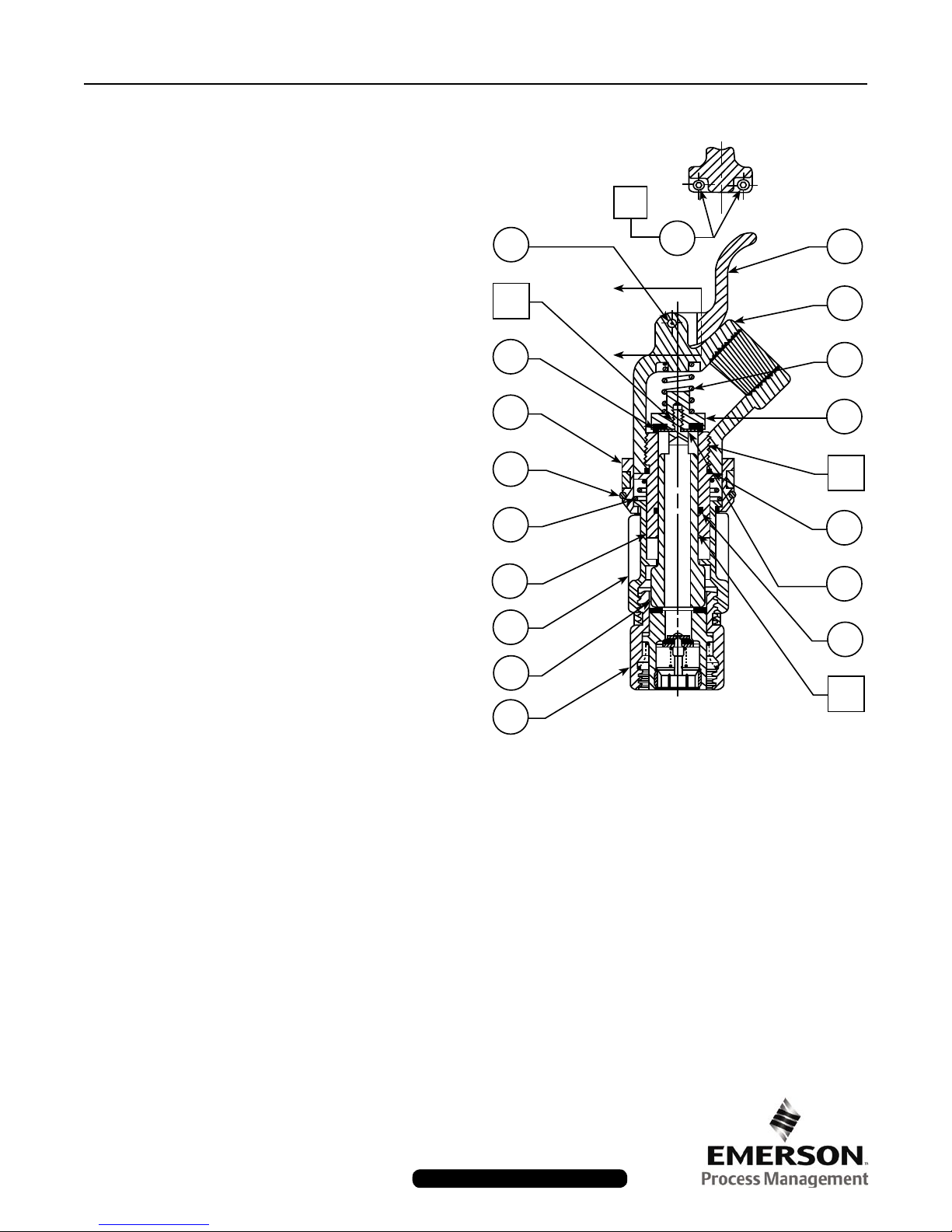
Parts List
Key Part Name
1 Body
2 Yoke (2 required)
3 Coupler
4 Handle
5 Dowel Pin
6 Guide
7 O-Ring
8 X-Ring
9 Flow Tube
10 Disc Holder
11 Disc
12 Washer
13 Flat Spring
SECTION: A ~ A
20
5
19
A
18
4
1
A
11
2
16
13
6
3
14
10
20
7
12
8
9
21
22
Figure 2. Type N480
Key Part Name
14 Spring
15 Linkage (2 required)
16 Snap Ring
17 Rivet (2 required)
18 Set Screw (2 required)
19 Apply Loctite No. 262
20 Apply Loctite No. 242
21 Apply Magnalube-G
22 Type M470
Fisher and Fisher Regulators are marks owned by Fisher Controls International, LLC. The Emerson logo is a trademark and service mark of Emerson Electric Co. All other marks are the
property of their respective owners.
The contents of this publication are presented for informational purposes only, and while every effort has been made to ensure their accuracy, they are not to be construed as warranties or guarantees, express
or implied, regarding the products or services described herein or their use or applicability. We reserve the right to modify or improve the designs or specifications of such products at any time
without notice.
Fisher does not assume responsibility for the selection, use or maintenance of any product. Responsibility for proper selection, use and maintenance of any Fisher product remains solely with
the purchaser.
Emerson Process Management
Fisher Controls International, LLC.
P.O. Box 8004
McKinney, Texas 75070, USA
Telephone: 1 (800) 588-5853
Telephone: 1 (469) 293-4201
©Fis her Cont rols Interna tio nal, LLC., 1981; All R igh ts Reserv ed
ed
www.FISHERregulators.com/lp
 Loading...