

Page 1

Instruction Manual
Patnáctka
D103697X012
June 2019
le bouton vert
pour mise en
service
Type B NG
Appuyez sur
V
/Rok
/
Conform PED art 3.3
Conforme DESP art 3.3
Page 2
DESCRIPTION
TYPE B NG REGULATOR
The Type B NG is a two-stage pressure reducing
regulator with an automatic safety device to
avoid outlet over-pressure (relief valve venting to
atmosphere) or stopping the gas ow in the event
of an abnormal drop in inlet or outlet pressure or
an excess ow condition.
Rearming is manual by using the push-button and
depending on models (B6 version only) a valve may
be associated. A removable vent lter is situated
in the inlet connection, and a vent screen (see
schematic, item V).
The underground model is treated for anti-corrosion
and is painted.
Maximum allowable pressure: 5 bar
Operating temperature: -20 / 60°C
INSTALLATION
CAUTION
• To be used with clean, dry and non-corrosive gas.
• All regulators, except for underground version,
must be protected from direct contact of water
and corrosive atmosphere due to construction
materials base with zinc, copper and aluminium
(cabinet installation recommended).
• Recommended installation positions : inlet and/
or outlet in vertical position.
• To avoid: vent facing upwards, without protector
or connector, in humid conditions (risk of water
penetration due to rain or condensation).
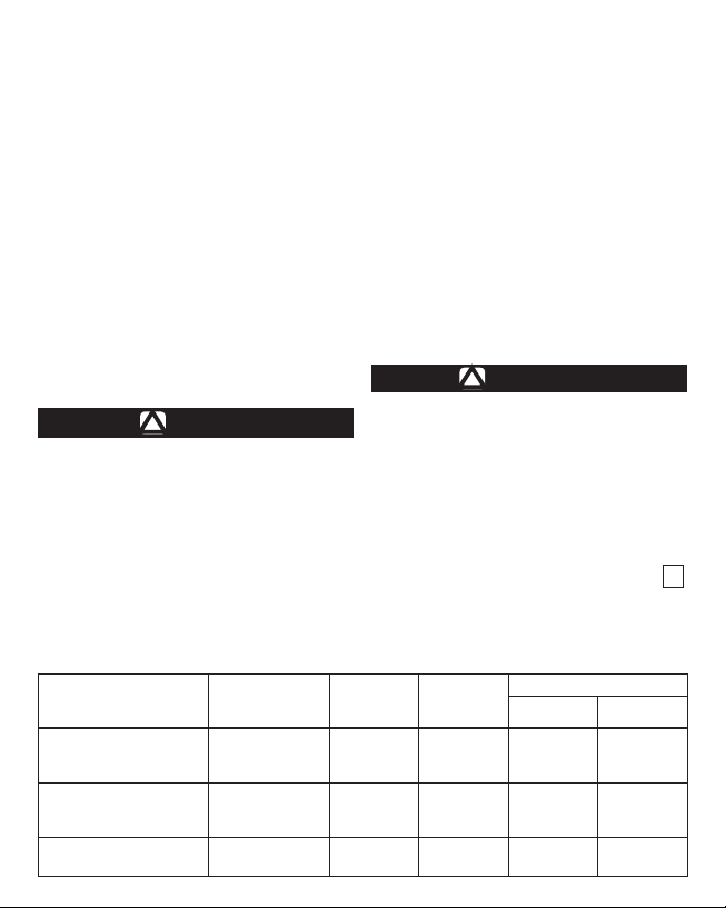
Gas Type Density
3
Manufactured gas (n)m
• Butane air
• Propane air
Natural gas (n)m
• Group L
• Group H
LP-gas kg/h
• Propane 1.56 2.017 37 7.2 12
/h
3
/h
1.20
1.15
0.64
0.61
Before connecting :
• Do not weld the inlet and outlet connections with
the regulator in place.
• Remove the protective capsules from the inlet
and outlet connections.
• Ensure that the pipeline is perfectly clean.
• Place the O-ring(s), (according to model)
greasing is recommended.
Connection
• Respect the gas ow direction indicated on the
regulator body.
• Respect the tightening torques by using a
dynamometric wrench (inlet with tight shuto
metal = 40 N•m, others according to O-ring used).
!
WARNING
Do not re-orientate the regulator after tightening
connections, under no circumstances should
the regulator be put under any geometrical or
dimensional consecutive force between inlet
and outlet sides.
When connecting the vent (residential areas,
underground) the diameter used should not be
inferior to 10 mm and should not be obstructed.
COMMISSIONING OR REARMING
Close the downstream valve (if existent). Open the
upstream valve. Press on the green button for a
few seconds, then release. Open the downstream
valve (if existent).
Volume
Weight
kg/m
1.552
1.487
0.827
0.789
Pressure
Setpoint
3
11
11
27
21
Nominal Flow
B6 B10
4
4
6
6
1
7
7
10
10
Page 3

Type B NG
Webadmin.Regulators@emerson.com
Fisher.com
Facebook.com/
EmersonAutomationSolutions
LinkedIn.com/company/emersonautomation-solutions
Twitter.com/emr_automation
Emerson Automation Solutions
Americas
McKinney, Texas 75070 USA
T +1 800 558 5853
Asia Pacic
Singapore 128461, Singapore
T +65 6777 8211
+1 972 548 3574
Europe
Bologna 40013, Italy
T +39 051 419 0611
D103697X012 © 2017, 2019 Emerson Process Management Regulator Technologies, Inc. All rights reserved. 06/19.
The Emerson logo is a trademark and service mark of Emerson Electric Co. All other marks are the property
of their prospective owners. Fisher™ is a mark owned by Fisher Controls International LLC, a business of
Emerson Automation Solutions.
The contents of this publication are presented for informational purposes only, and while every eort has been
made to ensure their accuracy, they are not to be construed as warranties or guarantees, express or implied,
regarding the products or services described herein or their use or applicability. All sales are governed by our
terms and conditions, which are available upon request. We reserve the right to modify or improve the designs
or specications of such products at any time without notice.
Emerson Process Management Regulator Technologies, Inc does not assume responsibility for the selection,
use or maintenance of any product. Responsibility for proper selection, use and maintenance of any
Emerson Process Management Regulator Technologies, Inc. product remains solely with the purchaser.
Francel SAS, 3 Avenue Victor Hugo,CS 80125, Chartres 28008, France
SIRET 552 068 637 00057 APE 2651B, N° TVA : FR84552068637, RCS Chartres B 552 068 637,
SAS capital 534 400 Euro
Middle East and Africa
Dubai, United Arab Emirates
T +971 4 811 8100
 Loading...