

Page 1
Instruction Manual
D101299X012
Fisherr RSS Lined Globe Valve
RSS Valve
September 2014
Contents
Introduction 1.................................
Scope of Manual 1.............................
Description 1.................................
Educational Services 2.........................
Specifications 3...............................
Installation 3..................................
Maintenance 5.................................
Packing Maintenance 8.........................
Replacing Packing and Bushing Inserts 8..........
Trim Maintenance 11..........................
Disassembly 11............................
Assembly 12..............................
Parts Ordering 13...............................
Parts List 13...................................
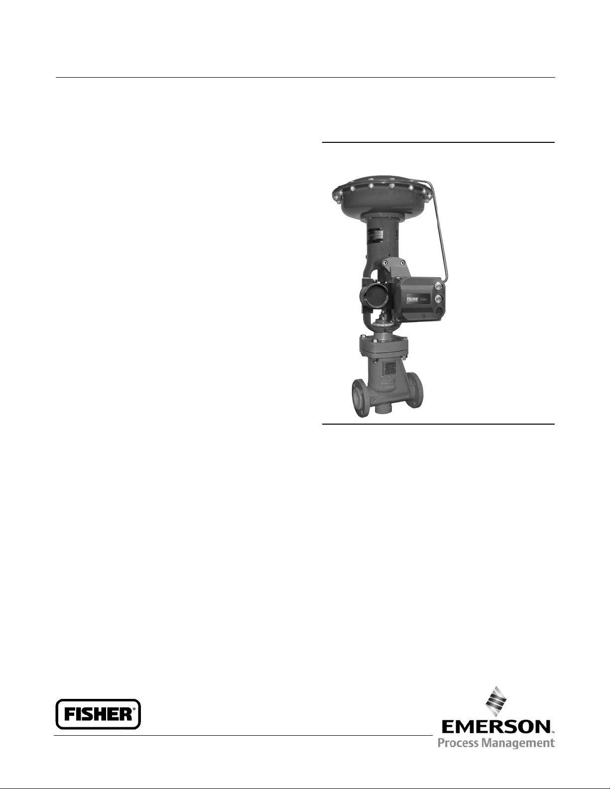
Figure 1. Fisher RSS Valve with 667 Actuator
and FIELDVUE™ DVC6200 Digital Valve Controller
W9164-2
Introduction
Scope of Manual
This instruction manual includes installation, maintenance, and parts information for NPS 1 through NPS 4 Fisher RSS
lined globe valves. Refer to separate manuals for instructions covering the actuator, positioner, and accessories.
Description
The RSS lined globe-style valve (figure 1) has pure-modified PTFE trim parts, push-down-to- close action, and positive
shutoff. This valve is intended for applications involving severely corrosive and toxic flowing media, and is well-suited
for pure media applications, as well. The RSS valve body provides an economical alternative to alloy valve bodies in a
wide variety of applications.
Do not install, operate, or maintain an RSS valve without being fully trained and qualified in valve, actuator, and
accessory installation, operation, and maintenance. To avoid personal injury or property damage, it is important to
carefully read, understand, and follow all the contents of this manual, including all safety cautions and warnings. If you
have any questions about these instructions, contact your Emerson Process Management sales office before
proceeding.
www.Fisher.com
Page 2
RSS Valve
September 2014
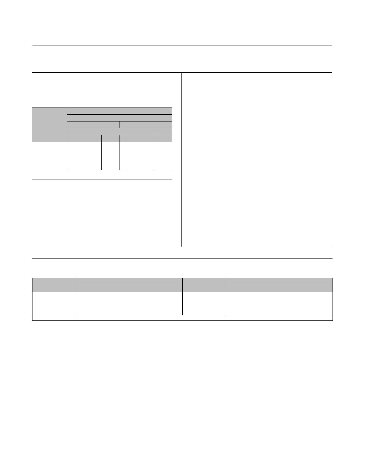
Table 1. Specifications
Instruction Manual
D101299X012
Valve Sizes
NPS J 1, J 1-1/2, J 2, J 3, and J 4
Application Limits
Liquid Service: For cavitating applications, contact
your Emerson Process Management sales office
Face-To-Face and Flange Compatibility
Gas Service: Velocity ± 0.33 MACH
DUCTILE IRON
VALVE SIZE,
NPS
ASME
1
1-1/2
2
3
4
1.ForANSI/ISAface-to-facedimensions,seefigure9.
2.ForENface-to-facedimensions,seefigure9.
Raised-Face Flange
CL150 CL300
(1)
X
X
X
X
X
Face-To-Face
(2)
EN
X
X
X
X
X
ASME
X
X
X
---
---
(1)
Maximum Inlet Pressures and Temperatures
(1)
EN
(2)
---
---
---
---
---
Temperature Capabilities
Positive Pressure Service: -29 to 180_C
(-20 to 360_F)
Vacuum Service: -29 to 180_C (-20 to 360_F)
Standard Flow Characteristic/Valve Plug Style
Equal percentage
Flow Direction
Up through the seat ring (see figure 7)
See table 2
Downstream/Outlet Pressure Ratings
(1)
See figures 3 and 4
Shutoff Classification
Class VI per ANSI/FCI 70-2 and IEC 60534-4
1. The pressure or temperature limits in this manual,and any applicable standard limitations should not be exceeded.
Packing Arrangement
Braided PTFE rings
Dimensions and Weights
Seefigure9
Table 2. Maximum Allowable Inlet Pressures and Temperatures
TEMPERATURE, _C
-29 to 38
93
149
180
1. Includes valves with CL300 flanges.
PRESSURE, BAR
Ductile Iron Ductile Iron
19.7
17.9
15.9
14.8
(1)
TEMPERATURE, _F
-20 to 100
200
300
360
PRESSURE, PSIG
285
260
230
215
Educational Services
For information on available courses for Fisher RSS valves, as w ell as a variety of other products, contact:
Emerson Process Management
Educational Services - Registration
Phone: 1-641-754-3771 or 1-800-338-8158
E-mail: education@emerson.com
http://www.emersonprocess.com/education
2
Page 3

Instruction Manual
D101299X012
RSS Valve
September 2014
Specifications
SpecificationsfortheRSSvalveareshownintable1.Ifthevalveisshippedwiththeactuator,someofthevalve
specifications are on the valve nameplate, which is attached to the actuator. If the valve is shipped without the
actuator, the valve nameplate is wired to the valve.
Installation
WARNING
Always wear protective gloves, clothing, and eyewear when performing any maintenance operations to avoid personal
injury.
Personal injury or equipment damage caused by sudden release of pressure can result if the valve is installed where service
conditions could exceed the limits given on the nameplate or in table 1 or 2, or figure 3 or 4. To avoid such injury or
damage, use pressure-limiting or pressure-relieving devices to prevent service conditions from exceeding these limits.
Check with your process or safety engineer for any other hazards that may be present from exposure to process media.
If installing into an existing application, also refer to the WARNING at the beginning of the Maintenance section in this
instruction manual.
CAUTION
When ordered, the valve configuration and construction materials are selected to meet particular pressure, temperature,
pressure drop, and controlled fluid conditions. Since some valve body/trim material combinations are limited in their
pressure drop and temperature ranges, do not apply any other conditions to the valve without first contacting your
Emerson Process Management sales office.
CAUTION
Before installing the valve, inspect it to be certain that the valve cavity is free of foreign material. Use extra care in handling
to avoid damage to the exposed lining on the flanges. Clean out all pipelines to remove scale, welding slag, and any other
foreign materials that could cause erosion of the valve body lining.
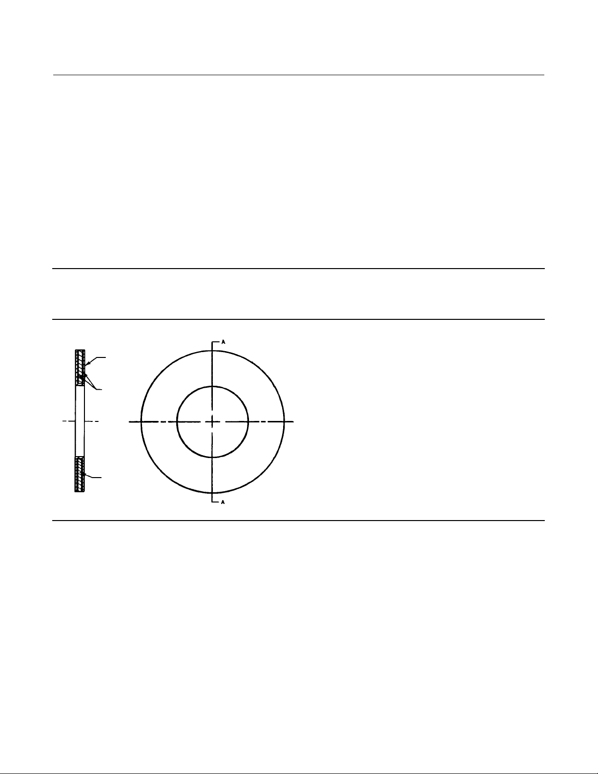
Use accepted piping practices when installing the valve in the pipeline. To minimize valve damage caused by expansion of
PTFE lined pipe, use a line flange gasket (figure 2). This gasket evenly distributes the piping loads across the valve flange
face and minimizes the potential for cutting or indenting the lined face on the valve flange.
3
Page 4
RSS Valve
September 2014
Instruction Manual
D101299X012
1. The control valve assembly should be installed in a horizontal pipeline with the valve stem in a vertical position.
Before installing in any other orientation, consult your Emerson Process Management sales office.
Flowthroughthevalvemustbeinthedirectionindicatedbythearrowcastonthevalve(figure7).
2. With a leak-off bonnet construction, remove the pipe plug (key 20, not shown) and install the leak-off piping into
thetappinginthebonnet(key2,figure10).
3. If continuous operation is required during inspection or maintenance, install a three-way bypass around the control
valve assembly.
4. For a valve used with a fail-closed actuator, remove the shim (key 24, not shown) from between the bonnet and the
travel stop. Discard the shim.
5. If the actuator and valve are shipped separately, refer to the appropriate actuator instruction manual for t he
actuator mounting procedure.
Note
Bench sets for Fisher 657 and 667 actuators must be adjusted after installation on the RSS valve. The heavy duty bellows on the
RSSvalvehasasignificantspringratethatmustbe included in the bench set for proper operation.
Figure 2. Typical Line Flange Gasket (Key 17)
A
PTFE
COMPOSITION
SECTION A-A
10B3224-C
A5039
STAINLESS STEEL
A
4
Page 5

Instruction Manual
D101299X012
RSS Valve
September 2014
Maintenance
Valve parts are subject to normal wear and must be inspected and replaced as necessary. Inspection and maintenance
frequency depends on the severity of service conditions. This section includes instructions for packing and trim
replacement. All these maintenance operations may be performed with the valve in the line.
WARNING
Avoid personalinjury or property damage from sudden release of process pressure or bursting of parts. Before performing
any maintenance operations:
D Do not remove the actuator from the valve while the valve is still pressurized.
D Always wear protective gloves, clothing, and eyewear when performing any maintenance operations to avoid personal
injury.
D Disconnect any operating lines providing air pressure, electric power, or a control signal to the actuator. Be sure the
actuator cannot suddenly open or close the valve.
D Use bypass valves or completely shut off the process to isolate the valve from process pressure. Relieve process pressure
from both sides of the valve. Drain the process media from both sides of the valve.
D Vent the power actuator loading pressure and relieveany actuator spring precompression.
D Use lock-out procedures to be sure that the above measures stay in effect while you work on the equipment.
D The valve packing box may contain process fluids that are pressurized, even when the valve has been removed from the
pipeline. Process fluids may spray out under pressure when removing the packing hardware or packing rings, or when
loosening the packing box pipe plug.
D Check with your process or safety engineer for any other hazards that may be present from exposure to process media.
Note
Whenever a line flange gasket (figure 2) seal is disturbed by removing the valve from the line, install a new gasket on reassembly.
This is necessary to ensure a good gasket seal.
5
Page 6

RSS Valve
September 2014
Figure 3. Downstream/Outlet Pressure Ratings (Positive Pressure Service)
1501005020
302
E0981
-29
232
217
203
188
174
159
145
130
116
101
87
gauge pressure (psi)
72.5
58
43.5
29
14.5
0
68
-20
HEAVY-DUTY BELLOWS WITH METAL SUPPORT RINGS
STANDARD PTFE BELLOWS
122 212
180_C
16
15
14
13
12
11
10
9
8
7
6
5
4
3
2
1
0
360_F
Instruction Manual
D101299X012
gauge pressure (bar)
NOTE: THE LINER DOES N OT LIMIT THE DOWNSTREAM PRESSURE RATING IN POSITIVE PRESSURE SERVICES.
Figure 4. Downstream/Outlet Pressure Ratings (Vacuum Service)
1501005020
E0980
14.5
7.25
4.35
2.9
1.45
0.72
0.43
0.29
0.14
vacuum (psia)
0.07
0.04
0.03
0.015
68 122 212 302
180_C
1
0.5
0.3
0.2
0.1
0.05
0.03
0.02
0.01
0.005
0.003
0.002
0.001
360_F
vacuum (bar)
THE PFA LINER CANNOT
BE USED IN THIS AREA
PFA LINING
6
Page 7

Instruction Manual
D101299X012
Figure 5. Bonnet, Travel Stop, and Seat Ring Installation Detail
VALVE
STEM
(KEY 5)
LOCKNUT
(KEY 10)
YOKE
LOCKNUT
(KEY 14)
TRAVEL
STOP
(KEY15)
0.6 mm
(O.020 INCH) GAP
BONNET
(KEY 2)
RSS Valve
September 2014
BONNET
LOCATING
DIAMETER
29B2880-B
E1021
EQUAL AT ALL BOLTING
LOCATIONS
BELLOWS
(KEY 6)
VALVE
PLUG
(KEY 3)
40B4191-E
SEAT RING
CONTACT SURFACE
SEAT RING
SEALING LEDGE
7
Page 8

RSS Valve
September 2014
Instruction Manual
D101299X012
Packing Maintenance
Key numbers are shown in figure 10.
The packing consists of braided packing rings (key 13). The packing box is only a safety measure in case of a leak
through the bellows (key 6). Therefore, the packing follower (key 11) is tightened to 1.13 NSm(10lbfSin) of torque
and then loosened one half turn. To detect a leak through the bellows (key 6), the bonnet (key 2) can be provided with
a connection for leak-off piping.
Replacing Packing and Bushing Inserts
Key numbers are shown in figure 10.
1. Isolatethecontrolvalvefromthelinepressure.Releasepressure from both sides of the valve and drain the process
media from both sides of the valve.
2. Exhaust all actuator pressure, and disconnect the operating lines from the actuator and any leak-off piping from the
bonnet (key 2). Disconnect the actuator stem connector, and then remove the actuator from the valve by
unscrewingtheyokelocknut(key14).
3. Remove any travel indicator parts, the locknut (key 10), and the travel stop (key 16) from the valve stem (key 5)
threads.
CAUTION
Follow the procedures as described in the next steps to prevent damage to the bonnet sealing surface and to prevent
packing box leakage.
4. Remove the packing follower (key 11). Unscrew the cap screws (key 7) and hex nuts (key 8) that secure the bonnet
(key 2) to the valve (key 1). Then, carefully lift the bonnet off and set it on a protective surface to prevent damage to
the bonnet sealing surface. If the valvestem,bellows,andvalveplug(keys5,6,and3)comeoutwiththebonnet,
remove these parts from the bonnet.
5. Remove bushing inserts, packing rings, and packing box ring (keys 13, 12, 28, and 29).
6. Clean the packing box, packing box ring, and packing follower.
7. Inspect the valve stem and packing box surfaces for any sharp edges that might cut the packing. Scratches or burrs
could damage new packing or cause packing box leakage. If the surface condition cannot be improved by light
sanding, replace the damaged parts.
8. Install bushing inserts (keys 28 and 29).
9. Install the bonnet (key 2) over the valve stem (key 5). Slide the bonnet down until it properly engages the bonnet
locating diameter (figure 5) of the valve.
Note
In order to ensure accurate positioning of the valve plug (key 3) and seat ring (key 4), clearance between the valve and bonnet at
all bolting locations (figure 5) must be equal and approximately 2.0 mm (0.080 inches) for NPS 1 through 4 valves. Be sure to
measure the clearance in the next step.
10. Tighten the cap screws and hex nuts (keys 7 and 8) in a crisscross pattern to a maximum torque value of 50 NSm
(37 lbfSft). To ensure accurate positioning of the valve plug (key 3) into the seat ring (key 4), check the gap between
8
Page 9

Instruction Manual
D101299X012
RSS Valve
September 2014
the valve and bonnet with a feeler gauge (figure 5). At all bolting locations, the gap must be equal and
approximately 2.0 mm (0.080 inches) for NPS 1 through 4 valves. In order to keep the gap equal, the individual
bolts may have to be tightened to different torque levels.
Note
Due to the cold flowing tendency of the valve liner, this procedure should be repeated upon installation and after the first thermal
cycle of the valve.
11. Install the packing rings, packing box ring, and packing follower (keys 13, 12, and 11) over the valve stem. Tighten
the packing follower to 1.13 NSm(10lbfSin)oftorquetoensurethepackingrings are seated. After the packing
rings are seated, loosen the packing follower one half turn.
12. Manually press the valve stem (key 5) into the valve until the valve plug contacts the seat ring.
CAUTION
Improper adjustment in step 13 might cause damage to trim parts. Perform this step carefully.
13. Thread the travel stop (key 16) onto the valve stem until there is a 0.5 mm (0.020 inch) gap between the bottom
surface of the travel stop legs and the top of the bonnet (figure 5).
14. Thread the locknut (key 10) onto the stem and tighten it against the travel stop.
15. Mount the actuator and secure it with the yoke locknut (key 14). Connect the actuator stem and valve stem
according to the procedure in the appropriate actuator instruction manual.
Figure 6. Typical Locking Rope Installation
W9165-1
WITH LOCKING ROPE PARTIALLY REMOVED WITH LOCKING ROPE INSTALLED
W9166-1
9
Page 10

RSS Valve
September 2014
Figure 7. Fisher RSS Valve Body Shown with Tool Used to Remove or Install Seat Ring
SEAT
RING
SEAT
RING
W4473
TOOL
Instruction Manual
D101299X012
Table 3. Seat Ring Tool Dimensions
VALVE
SIZE,
NPS
1
1-1/2
2
3
4
VALVE
SIZE,
NPS
1
1-1/2
2
3
4
A B C
36.9
37.2
54.0
54.2
65.1
65.3
91.3
91.5
105.9
106.2
A B C
1.45
1.46
2.13
2.14
2.56
2.57
3.59
3.60
4.17
4.18
DIMENSIONS (MILLIMETERS)
D E F G
47.2
47.5
63.9
64.1
76.2
76.5
103.7
104.2
118.2
118.5
54.8
55.6
71.8
72.6
83.7
84.5
111.9
112.7
126.2
127.0
6.4 4.8
7.1 5.6
7.1 5.6
7.1 5.6
7.1 5.6
DIMENSIONS (INCHES)
D E F G
1.86
1.87
2.52
2.53
3.00
3.01
4.09
4.10
4.66
4.67
2.16
2.19
2.83
2.86
3.30
3.33
4.41
4.44
4.97
5.00
1/4 3/16
9/32 7/32
9/32 7/32
9/32 7/32
9/32 7/32
7.9
7.6
7.9
7.6
7.9
7.6
7.9
7.6
7.9
7.6
0.31
0.30
0.31
0.30
0.31
0.30
0.31
0.30
0.31
0.30
190
222
222
300
300
7-1/2
8-3/4
8-3/4
11-7/
8
11-7/
8
Figure 8. Seat Ring Tool
7.9
(5/16)
30_
15.8
(5/8)
DE
A3520-1
139.7
(5-1/2)
A4
B4
C4
9.5
(3/8)
3.9
(5/32)
F
G
mm
(INCH)
10
Page 11

Instruction Manual
D101299X012
RSS Valve
September 2014
Table 4. Recommended Seat Ring Torque
Valve Size,
NPS
1
1-1/2
2
3
4
Newton
Meters
8
23
30
50
50
Pound-Force
Inches
71
---
---
---
---
Pound-Force
Feet
--17
22
37
37
Trim Maintenance
Key numbers are shown in figure 10.
Disassembly
1. Remove the actuator and the bonnet as described in steps 1 through 4 of the Replacing Packing and Bushing Inserts
section.
2. Inspect parts for wear or damage that would prevent proper operation of the valve.
3. To replace the bellows (key 6), unscrew the valve stem (key 5) in a counterclockwise rotation. Install the valve stem
into the new bellows with a clockwise rotation by hand. Do not overtighten.
4. To remove the valve plug (key 3), use pliers to remove the locking rope (key 9) that locks the valve plug to the
bellows(key6)asshowninfigure6.Thenunscrewtheplugfromthebellows.
Note
To avoid cold flow of the valve liner and deforming of the valve body seat ring threads and seat ring contact surfaces, promptly
install a replacement seat ring according to step 1 of the Assembly procedures.
5. Toremovetheseatring(key4),usetheseatringtool(figure7or8)thatcanbeorderedfromthePartsListsection
or made according to the dimensions in figure 8 and table 3. To avoid cold flow of the valve liner and deforming of
the valve body seat ring threads and seat ring contact surfaces, promptly install a replacement seat ring according
to step 1 of the Assembly procedures.
11
Page 12

RSS Valve
September 2014
Figure 9. Dimensions and Weights
ANSI/ISA CL150 FACE-TO-FACE DIMENSIONS
MATING WITH CL150 FLANGES
Valve
Size
NPS mm kg
1
1-1/2
2
3
4
NPS Inches Pounds
1
1-1/2
2
3
4
Valve
Size
NPS mm kg
1
1-1/2
2
NPS Inches Pounds
1
1-1/2
2
A B D
184.0
222.0
254.0
298.0
350.0
7.25
8.75
10.00
11.75
13.78
ANSI/ISA CL300 FACE-TO-FACE DIMENSIONS
A B D
197.0
235.0
267.0
7.75
9.25
10.50
Dimensions
83.0
97.0
107.0
121.0
176.0
3.27
3.82
4.21
4.76
6.94
MATING WITH CL300 FLANGES
90.0
101.0
115.0
3.54
3.97
4.53
185.0
225.0
230.0
340.0
350.0
7.28
8.86
9.06
13.39
13.78
Dimensions
185.0
225.0
230.0
7.28
8.86
9.06
Approximate
E
108.0
127.0
152.4
190.5
220.0
4.25
5.00
6.00
7.50
8.66
Approximate
E
123.8
156.0
165.0
4.87
6.14
6.50
Weight
10
17
20
39
42
23
36
43
86
92
Weight
11
18
20
25
40
45
E4
10B4744-G
A5216-1
Instruction Manual
D101299X012
MATCH LINE
FOR ACTUATOR
D
B
A
Assembly
CAUTION
To avoid damage to the seat ring sealing surface and/or threads in the valve body liner, make or order the seat ring tool
shown in figures 7 and 8. Installing the seat ring using other tools might cause permanent damage to the seat ring sealing
surface and/or threads allowing excessive leakage of the valve.
1. Install the seat ring (key 4) with the seat ring tool (figure 7 or 8) that can be ordered from the Parts List or made
according to the dimensions in table 3 and figure 8. Tighten the seat ring until contac t is felt between the sealing
ledge of the seat ring and its mating surface in the valve (figure 5). At this point, tighten the seat ring one quarter
turn or to the torque values listed in table 4.
2. To install the valve plug (key 3), screw the valve plug onto the bellows and insert the locking rope with pliers (figure
6).
3. Install the assembled valve plug, bellows, and valve stem (keys 3, 6, and 5). For metal bellows, install the gasket
(key 27).
4. Install the bonnet according to steps 9 and 10 of the Replacing Packing and Bushing Inserts procedure.
12
Page 13

Instruction Manual
D101299X012
RSS Valve
September 2014
5. Tighten the packing follower (key 11) to 1.13 NSm(10lbfSin)oftorquetoensurethepackingringsareseated.After
the packing rings are seated loosen the packing follower one half turn.
6. Perform steps 12 through 15 of the Replacing Packing and Bushing Inserts section.
Parts Ordering
Each valve body-bonnet assembly is assigned a serial number, which can be found on the valve nameplate. Refer to
this serial number when contacting your Emerson Process Management sales office for technical assistance. If the
valve is shipped with the actuator, the valve nameplate is attached to the actuator. If the valve is shipped without the
actuator, the valve nameplate is wired to the valve. When ordering replacement parts, refer to this serial number and
to the part number from the following Parts List.
WARNING
Use only genuine Fisher replacement parts. Components that are not supplied by Emerson Process Management should
not, under any circumstances, be used in any Fisher valve, because they may void your warranty, might adversely affect the
performance of the valve, and could cause personal injury and property damage.
Parts List
Note
Part numbers are shown for recommended spares only. Forpart
numbers not shown, contact your Emerson Process Management sales
office.
Except where indicated, sizes shown are valve body sizes.
Key Description Part Number
1 Valve Body or valve body/ring assembly
If you need a valve body or valve body/ring assembly as a
replacement part, order by valve size, serial number, and
desired material.
2 Bonnet/Bushing Assembly
If you need a bonnet/bushing assemblyas a replacement
part, order by valve size and stem diameter, serial number,
and desired material.
3* Valve Plug See following table
4* Seat Ring See following table
5* Valve Stem
Stainless steel
NPS 1 21B7543X012
NPS 1-1/2 & 2 21B7544X012
NPS 3 & 4 20B2511X012
6* Bellows Seefollowing table
7 Cap Screw
7Stud
8HexNut
9* Locking Rope, PTFE
NPS 1,1-1/2, & 2 20B2519X022
NPS 3& 4 20B2519X032
Key Description Part Number
10 Locknut
11 PackingFollower
12* Packing Box Ring
Stainless steel
NPS 1, 1-1/2, 2, 3,& 4 20B2495X012
13* Packing Ring, PTFE
NPS 1, 1-1/2, & 2 (2 req'd) 20B2504X012
NPS 3 & 4 (3 req'd) 20B2504X012
14 Yoke Locknut
16 TravelStop
17* Line Flange Gasket (for use only if specified, see figure 2),
PTFE/composition/stainlesssteel (2 req'd)
For CL150
NPS 1 10B3223X022
NPS 1-1/2 10B3224X022
NPS 2 10B3225X022
NPS 3 10B3226X022
NPS 4 10B3227X022
For CL300
NPS 1 11B5886X022
NPS 1-1/2 11B5887X022
NPS 2 11B5888X022
18 LineFlange Cap Screws (for NPS 2 useonly)
20 Pipe Plug (for use w/tapped bonnet only--not shown)
21 Seat Ring Tool (for use only if specified--see figure 7 or 8)
22 Nameplate Seal & Wire (not shown)
24* Shim (for use only w/fail-to-close actuator during
shipping [notshown]), aluminum 10B4192X012
25 Identification Plate, (not shown)
26 DriveScrew
28* Bushing Insert, Carbon-filled PTFE
NPS 1, 1-1/2, & 2 21B9345X042
NPS 3 & 4 (2 req'd) 21B9345X032
29* Bushing Insert, Carbon-filled PTFE
NPS 1, 1-1/2, & 2 21B9345X022
*Recommended spare parts
13
Page 14

RSS Valve
September 2014
Figure 10. Fisher RSS Valve Assembly
Instruction Manual
D101299X012
SEE VIEW A
40B4191-E
NOTE: KEYS 17, 19, 20,21, 22
23, 24, 25, AND 26 ARE NOT SHOWN
COMPLETE VALVE BODY ASSEMBLY
BELLOWS
BELLOWS
SUPPORT
RING
LOCKING
ROPE
SEE VIEW B
40B4191-E
VIEW A
DETAIL OF BONNET
FORNPS3AND4VALVES
14
A3598-3
VIEW B
VALVE
PLUG
DETAIL OF HEAVY DUTY
PTFE BELLOWS CONSTRUCTION
DETAIL OF NPS 3 AND 4 U-PLUG
Page 15

Instruction Manual
D101299X012
RSS Valve
September 2014
Key3*ValvePlugfor8through96mm(0.3125through4-inch)PortDiameters(IncludesLockingRope,Key9)
VALVE SIZE,
NPS
mm Inches
PORT DIAMETER
8
1
15
20
25
1-1/2
2
3
4
1. Inch equivalents of these metric port diameters have been roundedto common fractional diameters. Actualdiameter of the 15 millimeter port is 0.591 inches, of the 40 millimeter porti s
1.575 inches, and of the 96 millimeter port is3.780 inches.
2. NPS 1 valve with 15 mm (0.591 inch)travel.
25
40
30
50
50
80
65
96
(1)
PART NUMBER
0.3125
0.5
0.75
1
1
1.5
1.1875
2
2
3.1875
2.5
4
23B9209X022
23B9208X022
23B9207X022
23B9206X022
21B9632X062
21B9631X062
21B9634X062
21B9633X062
22B0701X062
22B0434X062
22B0702X062
21B5680X062
(2)
(2)
(2)
(2)
Key 4* Seat Ring
VALVE
SIZE,
NPS
mm Inches
8
1
15
20
25
1-1/2
2
3
4
1. Inch equivalents of these metric port diameters have been roundedto common fractional diameters. Actualdiameter of the 15 millimeter port is 0.591 inches, of the 40 millimeter porti s
1.575 inches, and of the 96 millimeter port is3.780 inches.
25
40
30
50
50
80
65
96
PORT
DIAMETER
(1)
0.3125
0.5
0.75
1
1
1.5
1.1875
2
2
3.1875
2.5
4
PART NUMBER
20B4169X032
20B4170X042
20B4172X042
20B2509X032
20B4174X032
20B2508X032
20B4164X032
20B2507X032
20B4159X032
20B2506X032
20B4157X032
20B2505X032
Key 6* Bellows
VALVE SIZE, NPS PORT DIAMETER PART NUMBER
1 All 29B2879X022
1-1/2 and2 All 29B2880X022
3and4 All 29B2881X022
15
Page 16

RSS Valve
September 2014
Instruction Manual
D101299X012
Neither Emerson, Emerson Process Management, nor any of their affiliated entities assumes responsibility for the selection, use or maintenance
of any product. Responsibilityfor proper selection, use, and maintenance of any product remains solely with the purchaser and end user.
Fisher and FIELDVUE are marks owned byone of the companies in the Emerson Process Management business unit of Emerson Electric Co. Emerson Process
Management, Emerson, and the Emerson logo are trademarks and service marks of Emerson Electric Co. All other marks are the property of their respective
owners.
The contents of this publication are presented for informational purposes only, and while every effort has been made to ensure their accuracy, they arenot
to be construed as warranties or guarantees, express or implied, regarding the products or services described herein or their use or applicability. All sales are
governed by our terms and conditions, which are available upon request. We reserve the rightto modify or improve the designs or specifications of such
products at any time without notice.
Emerson Process Management
Marshalltown, Iowa 50158 USA
Sorocaba, 18087 Brazil
Chatham, Kent ME4 4QZ UK
Dubai, United Arab Emirates
Singapore 128461 Singapore
www.Fisher.com
16
E 1986, 2014 Fisher Controls International LLC.All rights reserved.
 Loading...