

Emerson Fisher 161AY Series, Fisher 161EB Series, Fisher EZR, Fisher PRX Series Instruction Manual
Instruction Manual
D102600X012
August 2018
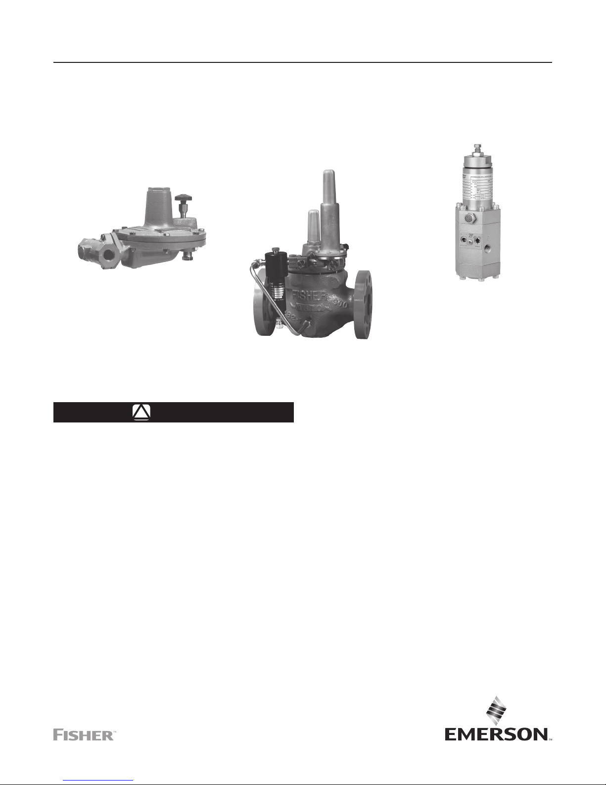
Type EZR Pressure Reducing Regulator
161AY SERIES PILOT
TYPE PRX PILOT
Type EZR
Figure 1. Type EZR Pressure Reducing Regulator
WARNING
!
Failure to follow these instructions or
to properly install and maintain this
equipment could result in an explosion
and/or re causing property damage and
personal injury or death.
Fisher™ regulators must be installed,
operated and maintained in accordance
with federal, state and local codes, rules
and regulations and Emerson Process
Management Regulator Technologies, Inc.
(Emerson) instructions.
If the regulator vents gas or a leak
develops in the system, service to the unit
may be required. Failure to correct trouble
could result in a hazardous condition.
Call a gas service person to service the
unit. Only a qualied person must install
or service the regulator.
TYPE EZR REGULATOR
Introduction
Scope of the Manual
This instruction manual provides installation,
startup, adjustment, maintenance and parts ordering
information for Type EZR pressure reducing regulator,
Types 112 restrictor, 161AY, 161EB and PRX Series
pilot. Any accessories used with this regulator are
covered in their respective instruction manuals.
Product Description
The Type EZR pilot-operated, pressure reducing
regulators are used for natural gas, air or other
non-corrosive gas applications and include a
Type 112 restrictor and a 161EB, 161AY or
PRX Series pilot.
Pilot Type Descriptions
Type 161AY—Low-pressure pilot with an outlet
pressure range of 6 in. w.c. to 7 psig / 15 mbar to
0.48 bar. Pilot bleeds (exhausts) downstream through
the sense (control) line.

Type EZR
Specications
Specications for the Type EZR regulator are shown below. The control spring range for the pilot is marked on the
spring case of 161EB Series pilots and on the nameplate of 161AY and PRX Series pilots. Other information for
the main valve appears on the nameplate.
Main Valve Body Sizes, End Connection Styles
and Structural Design Ratings
(1)(2)
See Table 1
Maximum Inlet Pressures and Pressure Drops
(1)
Main Valve: See Table 10
Pilots: See Table 3
Restrictor: 1500 psig / 103 bar
Outlet (Control) Pressure Ranges
See Table 2
Main Valve Plug Travel
NPS 1, 1-1/4 x 1, 2 x 1 /
DN 25, 32 x 25, 50 x 25: 0.37 in. / 9.4 mm
NPS 2 / DN 50: 0.68 in. / 17 mm
NPS 3 / DN 80: 0.98 in. / 25 mm
NPS 4 / DN 100: 1.19 in. / 30 mm
NPS 6 / DN 150: 1.5 in. / 38 mm
NPS 8 / DN 200: 1.75 in. / 44 mm
1. The pressure/temperature limits in this Instruction Manual and any applicable standard or code limitation should not be exceeded.
2. End connections for other than ASME standard can usually be provided, contact your local Sales Ofce for assistance.
Type 161AYM—The monitor version of the Type 161AY
pilot. The pilot bleed (exhaust) is isolated from the sense
(control) line. This pilot is used in monitoring systems
requiring an isolated pilot bleed (exhaust).
Type 161EB—High accuracy pilot with an outlet
pressure range of 5 to 350 psig / 0.34 to 24.1 bar.
Pilot bleeds (exhausts) downstream through the sense
(control) line.
Type 161EBM—The monitor version of the Type 161EB
pilot. The pilot bleed (exhaust) is isolated from the sense
(control) line. This pilot is used in monitoring systems
requiring an isolated pilot bleed (exhaust).
Type 161EBH—The high pressure version of the
Type 161EB pilot with an outlet pressure range from
250 to 700 psig / 17.2 to 48.3 bar.
Type 161EBHM—The high pressure version of the
Type 161EBM pilot with an outlet pressure range from
250 to 700 psig / 17.2 to 48.3 bar.
Minimum and Maximum Differential Pressures
See Tables 4 and 10
Proportional Bands
See Table 2
Process Temperature Capabilities
See Table 8
Pressure Registration
External
Options
• Integral Slam-Shut Device
• Pre-piped Pilot Supply and Pilot Bleed
• Travel Indicator
• Inlet Strainer
• Type 252 Pilot Supply Filter
• Trim Package
• Restricted Capacity Trim
• Pilot Diaphragm for Pressure Loading
and sensitivity, an integral restrictor adjustment which
allows adjustable opening and closing speeds and
a damper adjustment which adjusts inlet pressure
variability and loading pressure oscillations.
Type PRX/120-AP—Outlet pressure range of 435 to
1000 psig / 30.0 to 69.0 bar. The Type PRX/120-AP
can be used as the pilot on single-stage pressure
reducing regulators, as the monitor pilot or working
pilot in wide-open monitor systems or as the working
pilot for monitoring and working regulators in the
working monitoring systems.
Type PRX/125—Identical to the Type PRX/120 except
the restriction screw is removed. The Type PRX/125
can only be used as the monitor override pilot on
working monitor applications.
Type PRX/125-AP—Identical to the Type PRX/120-AP
except the restriction screw is removed. The
Type PRX/125-AP can only be used as the monitor
override pilot on working monitor applications.
Type PRX/120—Outlet pressure range of 14.5 to
435 psig / 1.00 to 30.0 bar. The Type PRX/120 can be
used as the pilot on single-stage pressure reducing
regulators or as the monitor pilot or working pilot in
wide-open monitor systems. The Type PRX has a
double diaphragm which provides increased accuracy
For applications requiring extremely
tight control, using a Type 161AYM,
161EBM, 161EBHM or PRX/120 pilot will
increase the accuracy of the regulator.
(1)
(1)
Note
2
Type EZR
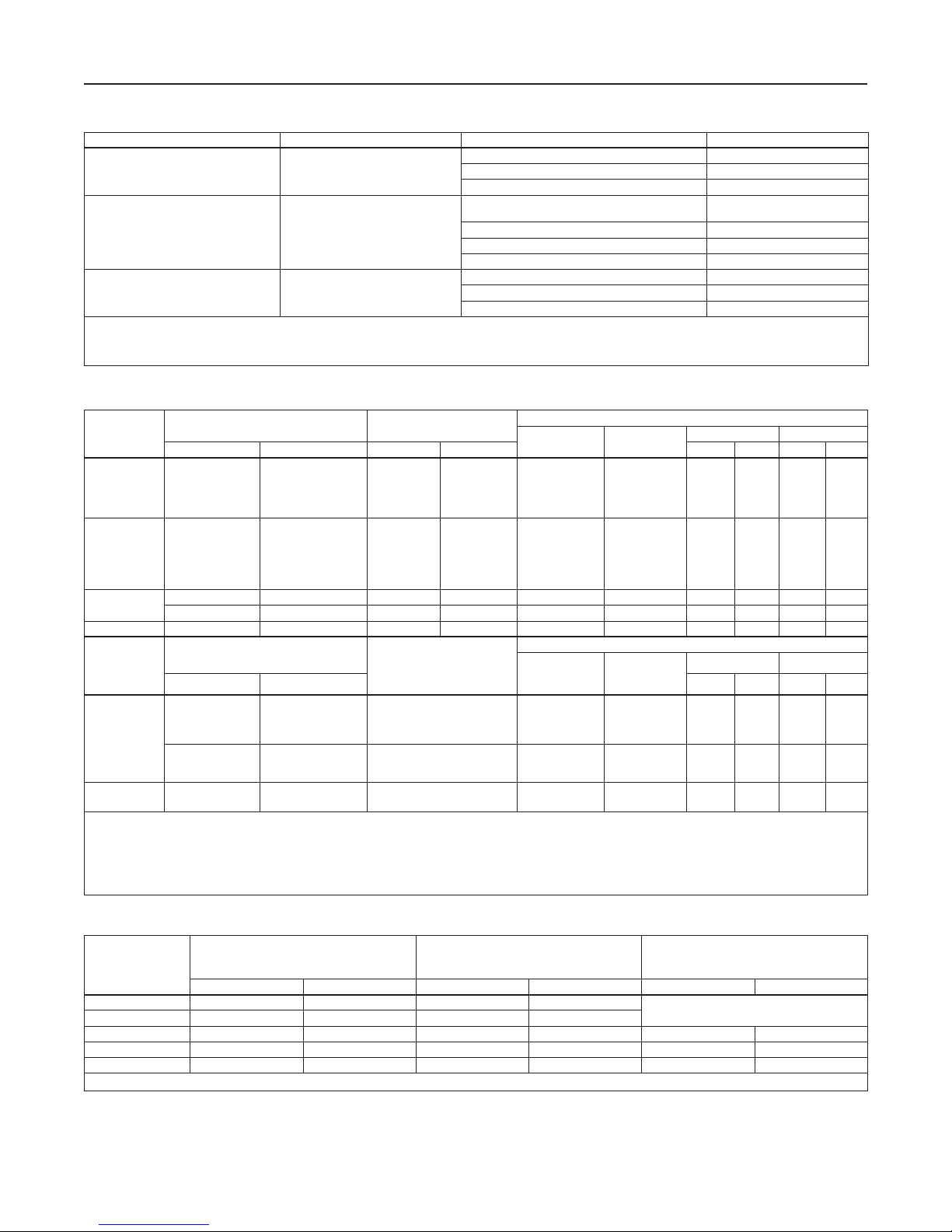
Table 1. Main Valve Body Sizes, End Connection Styles and Body Ratings
MAIN VALVE BODY SIZE, NPS / DN MAIN VALVE BODY MATERIAL END CONNECTION STYLE
2 x 1, 2, 3, 4 and 6 /
50 x 25, 50, 80, 100 and 150
(3)
1, 1-1/4 x 1
(4)
, 8 x 4
6 x 4
100,150 x 100, 200 x 100, 150,
200 x 150 and 300 x 150
, 2 x 1, 2, 3, 4,
(4)
(4)
, 6, 8 x 6
x 25, 50 x 25, 50, 80,
and 12 x 6
(4)
/ 25, 32
Cast iron
WCC Steel
NPT (NPS 2 x 1 and 2 / DN 50 x 25 and 50 only) 400 psig / 27.6 bar
CL125 FF 200 psig / 13.8 bar
CL250 RF 500 psig / 34.5 bar
NPT or SWE (NPS 1, 2 x 1 and 2 /
DN 25, 50 x 25 and 50 only)
CL150 RF 290 psig / 20.0 bar
CL300 RF 750 psig / 51.7 bar
CL600 RF or BWE 1500 psig / 103 bar
CL150 RF 290 psig / 20.0 bar
8 / 200 LCC Steel
CL300 RF 750 psig / 51.7 bar
CL600 RF 1500 psig / 103 bar
1. Ratings and end connections for other than ASME standard can usually be provided. Contact your local Sales Ofce for assistance.
2. See Tables 3, 8, 10 and 11 for diaphragm materials and additional pressure ratings.
3. Available in steel NPT only.
4. NPS 6 x 4, 8 x 4, 8 x 6, 12 x 6 / DN 150 x 100, 200 x 100, 200 x 150, 300 x 150 Types EZR and 399 bodies are not the same as the EW valve bodies and are not interchangeable.
Table 2. Outlet (Control) Pressure Ranges, Proportional Bands and Pilot Control Spring Information
(1)(3)
3 mbar
3 mbar
34 mbar
34 mbar
34 mbar
34 mbar
34 mbar
41 mbar
90 mbar
0.10
0.21
Part Number Color Code
(2)
1B653927022
(2)
1B537027052
(2)
1B537127022
(2)
1B537227022
(2)
1B537327052
(2)
17B1260X012
(2)
17B1262X012
(2)
17B1259X012
(2)
(2)
(2)
(5)
(5)
17B1261X012
17B1263X012
17B1264X012
17B1263X012 Blue 0.262 6.66 3.85 97.8
17B1264X012 Red 0.294 7.47 4.22 107
(1)
Part Number Color Code
M0255240X12
M0255230X12
M0255180X12
M0255220X12
M0255210X12
M0255200X12
M0255860X12
TYPE
OUTLET (CONTROL) PRESSURE RANGE PROPORTIONAL BAND
psig bar psig bar In. mm In. mm
161AY or
161AYM
161EB or
161EBM
161EBH or
161EBHM
(4)
161EB
TYPE
6 to 15 in. w.c.
0.5 to 1.2
1.2 to 2.5
2.5 to 4.5
4.5 to 7
5 to 15
10 to 40
30 to 75
70 to 140
130 to 200
200 to 350
250 to 450 17.2 to 31.0 3.5 0.24
400 to 700 27.6 to 48.2 7 0.48
30 to 300 2.1 to 20.7 6 0.41 15A9258X012 Green 0.243 6.17 1.88 47.7
OUTLET (CONTROL)
PRESSURE RANGE
15 to 37
34 to 83
83 mbar to 0.17 bar
0.17 to 0.31
0.31 to 0.48
0.34 to 1.0
0.69 to 2.8
2.1 to 5.2
4.8 to 9.7
9.0 to 13.8
13.8 to 24.1
1 in. w.c.
1 in. w.c.
0.5
0.5
0.5
0.5
0.5
0.6
1.3
1.5
3
ACCURACY CLASS (AC)
psig bar In. mm In. mm
14.5 to 26
23 to 44
PRX/120
PRX/125
PRX/120-AP
PRX/125-AP
1. Proportional band and Accuracy Class include outlet pressure drop plus hysteresis (friction), but do not include lockup.
2. Proportional band was determined with a pressure drop ranging from 50 to 150 psig / 3.5 to 10.3 bar. Approximately double the proportional band if the pressure drop is less than
50 psig / 3.5 bar.
3. With Type 112 restrictor set on 2. With Type PRX restrictor turn the restrictor screw one turn counterclockwise from fully seated.
4. Should only be used as the intermediate reduction pilot on the Type EZR worker/monitor systems.
5. Proportional band was determined with a pressure drop ranging from 100 to 300 psig / 6.9 to 20.7 bar. Approximately double the proportional band if the pressure drop is less than
100 psi / 6.9 bar.
41 to 80
73 to 123
116 to 210
203 to 334
319 to 435
435 to 1000 30.0 to 69.0 1% M0273790X12 Clear 0.335 8.51 3.93 99.8
1.00 to 1.8
1.6 to 3.0
2.8 to 5.5
5.0 to 8.5
8.0 to 14.5
14.0 to 23.0
22.0 to 30.0
2.5%
2.5%
2.5%
2.5%
1%
1%
1%
(1)
STRUCTURAL DESIGN RATING
1500 psig / 103 bar
PILOT CONTROL SPRING INFORMATION
Wire Diameter Free Length
Olive drab
Yellow
Light green
Light blue
Black
White
Yellow
Black
Green
Blue
Red
0.105
0.114
0.156
0.187
0.218
0.120
0.148
0.187
0.225
0.262
0.294
2.67
2.90
3.96
4.75
5.54
3.05
3.76
4.75
5.71
6.65
7.47
PILOT CONTROL SPRING INFORMATION
Wire Diameter Free Length
Yellow
Green
Blue
Black
Silver
Gold
Aluminum
0.110
0.126
0.138
0.157
0.177
0.197
0.236
2.79
3.20
3.50
3.99
4.50
5.00
5.99
3.75
4.31
4.13
3.94
4.13
3.75
3.75
4.00
3.70
3.85
4.22
2.16 54.9
2.16
2.00
2.00
95.2
109
105
100
105
95.2
95.2
102
94.0
97.8
107
54.9
50.8
50.8
(2)
TYPE
MAXIMUM INLET PRESSURE
psig bar psig bar psig bar
161AY 150 10.3 150 10.3
161EB and 161EBH 1500 103 1200 82.7
161AYM 150 10.3 150 10.3 150 10.3
161EBM and 161EBHM 1500 103 1200 82.7 1500 103
PRX Series 1480 102 1480 102 1480 102
1. Maximum pressure to prevent the casings from bursting during abnormal operation (leaking to atmosphere and internal parts damage may occur).
Table 3. Pilot Pressure Ratings
MAXIMUM EMERGENCY OUTLET PRESSURE OR
MAXIMUM EMERGENCY SENSE PRESSURE
MAXIMUM BLEED (EXHAUST) PRESSURE
(1)
FOR MONITOR PILOTS
- - - -
3
Type EZR
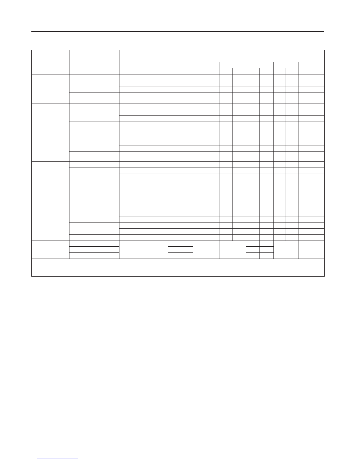
Table 4. Main Valve Minimum Differential Pressures
MAIN VALVE
BODY SIZE,
NPS / DN
1 and 1-1/4 x 1 /
25 and 32 x 25
2 x 1 / 50 x 25
2 / 50
3 / 80
4, 6 x 4 and, 8 x 4 /
100, 150 x 100
and 200 x 100
6, 8 x 6 and
12 x 6 /
150, 200 x 150
and 300 x 150
8 / 200
1. See Table 1 for structural design ratings, Table 3 for pilot ratings and Table 10 for maximum pressure ratings.
2. The yellow spring is only recommended for inlet pressures under 100 psig / 6.9 bar.
3. The red, black, purple, red stripe and black with white stripe springs are only recommended for applications where the maximum inlet pressure can exceed 500 psig / 34.5 bar.
4. 18B5955X012 (Red) is used on constructions with travel indicator while GE05504X012 (Purple) is used on non-travel indicator constructions.
MAIN SPRING PART
NUMBER AND
COLOR CODE
19B2400X012, Light Blue 17E68 and 17E88 24 1.7 29 2.0 31 2.2 24 1.7 31 2.2 40 2.8
GE12727X012, Black
19B2401X012,
Black with White Stripe
19B2400X012, Light Blue 17E68 and 17E88 24 1.7 29 2.0 31 2.2 24 1.7 31 2.2 40 2.8
19B2401X012,
Black with White Stripe
GE12501X012,
Red Stripe
19B0951X012, Yellow
18B2126X012, Green
18B5955X012, Red
GE05504X012, Purple
T14184T0012, Yellow
19B0781X012, Light Blue
19B0782X012, Black
T14184T0012, Yellow
18B8501X012, Green
18B8502X012, Red
19B0364X012, Yellow
19B0366X012, Green
19B0365X012, Red
GE09393X012, Yellow
GE09397X012, Red
(3)
(3)
(2)
(3)(4)
(3)(4)
(2)
(3)
(2)
(3)
(2)
(3)
(2)
(3)
DIAPHRAGM
MATERIAL
17E97 35 2.5 38 2.7 42 2.9 35 2.5 39 2.7 52 3.6
17E68 and 17E88 30 2.1 35 2.4 39 2.7 30 2.1 36 2.5 52 3.6
17E88 and 17E97 43 3.0 50 3.4 56 3.9 43 3.0 53 3.7 68 4.7
17E97 43 3.0 50 3.4 56 3.9 43 3.0 53 3.7 68 4.7
17E68 and 17E88 43 3.0 50 3.4 56 3.9 43 3.0 53 3.7 68 4.7
17E97 68 4.7 73 5.0 88 6.1 72 5.0 81 5.6 102 7.0
17E68 and 17E88 12 0.83 15 1.0 15 1.0 12 0.83 25 1.7 20 1.4
17E97 24 1.7 25 1.7 26 1.8 24 1.7 30 2.1 37 2.6
17E68 and 17E88 18 1.2 20 1.4 22 1.5 19 1.3 26 1.8 28 1.9
17E88 and 17E97 29 2.0 29 2.0 31 2.1 31 2.1 35 2.4 43 3.03
17E68 and 17E88 16 1.1 19 1.3 24 1.7 23 1.6 23 1.6 29 2.0
17E97 23 1.6 23 1.6 23 1.6 23 1.6 23 1.6 25 1.7
17E68 and 17E88 21 1.5 22 1.5 28 1.9 28 1.9 28 1.9 33 2.3
17E88 and 17E97 32 2.2 33 2.3 43 3.0 38 2.6 38 2.6 50 3.4
17E68 and 17E88 10 0.69 12 0.83 14 0.97 25 1.7 25 1.7 25 1.7
17E97 16 1.1 17 1.2 21 1.5 34 2.3 34 2.3 34 2.3
17E68 and 17E88 16 1.1 17 1.2 20 1.4 30 2.1 30 2.1 30 2.1
17E88 and 17E97 21 1.5 24 1.7 26 1.8 40 2.8 40 2.8 40 2.8
17E97 10 0.69 11 0.76 14 0.97 12 0.83 16 1.1 16 1.1
17E88 10 0.69 13 0.90 13 0.90 12 0.83 21 1.5 21 1.5
17E97 14 0.97 22 1.5 22 1.5 19 1.3 29 2.0 29 2.0
17E88 17 1.2 21 1.5 21 1.5 20 1.4 36 2.5 36 2.5
17E88 and 17E97 23 1.6 29 2.0 29 2.0 30 2.1 41 2.8 41 2.8
17E97
100% Trim 60% Trim 30% Trim 100% Trim 60% Trim 30% Trim
psi bar psi bar psi bar psi bar psi bar psi bar
16 1.1
26 1.8 30 2.1
MINIMUM DIFFERENTIAL, PERCENT OF CAGE CAPACITY
FOR 90% CAPACITY FOR 100% CAPACITY
- - - - - - - -
(1)
19 1.3
- - - - - - - -GE09396X012, Green 20 1.4 23 1.6
Principle of Operation
As long as the outlet (control) pressure is above
the outlet pressure setting, the pilot valve plug or
disk remains closed (Figure 2). Force from the main
spring, in addition to inlet pressure bleeding through
the Type 112 restrictor (the restrictor is integral in
the PRX Series pilots), provides downward loading
pressure to keep the main valve diaphragm and plug
assembly tightly shutoff.
When the outlet pressure decreases below the pilot
outlet pressure setting, the pilot plug or disk assembly
opens. Loading pressure bleeds downstream through
the pilot faster than it can be replaced through the
4
Type 112 restrictor. This reduces loading pressure on
top of the main valve diaphragm and plug assembly.
The force imbalance on the diaphragm allows the inlet
pressure to overcome the loading pressure and main
spring force and open the Type EZR diaphragm and
plug assembly.
As the outlet pressure rises toward the outlet pressure
setting, it compresses the pilot diaphragm against the
pilot control spring and allows the pilot valve plug or
disk close. Loading pressure begins building on the
Type EZR diaphragm and plug assembly. The loading
pressure, along with force from the main spring,
pushes the diaphragm and plug assembly onto the
tapered-edged seat, producing tight shutoff.

2
U
N
R
S
T
A
R
T
4
6
8
Type EZR
FLOW DIRECTION
B2625_2
161AY SERIES PILOT
TYPE 112 RESTRICTOR
TYPE 252 PILOT
SUPPLY FILTER
W7438_07/2008
TYPE EZR WITH TYPES 161EB PILOT, 112 RESTRICTOR AND 252 FILTER
161EB SERIES PILOT
MAIN SPRING
DIAPHRAGM AND
PLUG ASSEMBLY
E0790_09/2006
INLET PRESSURE
OUTLET PRESSURE
ATMOSPHERIC PRESSURE
LOADING PRESSURE
TYPE 252 SUPPLY FILTER
FLOW DIRECTION
TYPE EZR WITH PRX SERIES PILOT AND TYPE 252 FILTER
RESTRICTOR
PORT S
PORT L
MAIN SPRING
DIAPHRAGM AND
PLUG ASSEMBLY
Figure 2. Type EZR Operational Schematic
TYPE PRX PILOT
DAMPER
PORT B
PORT A
5
Type EZR
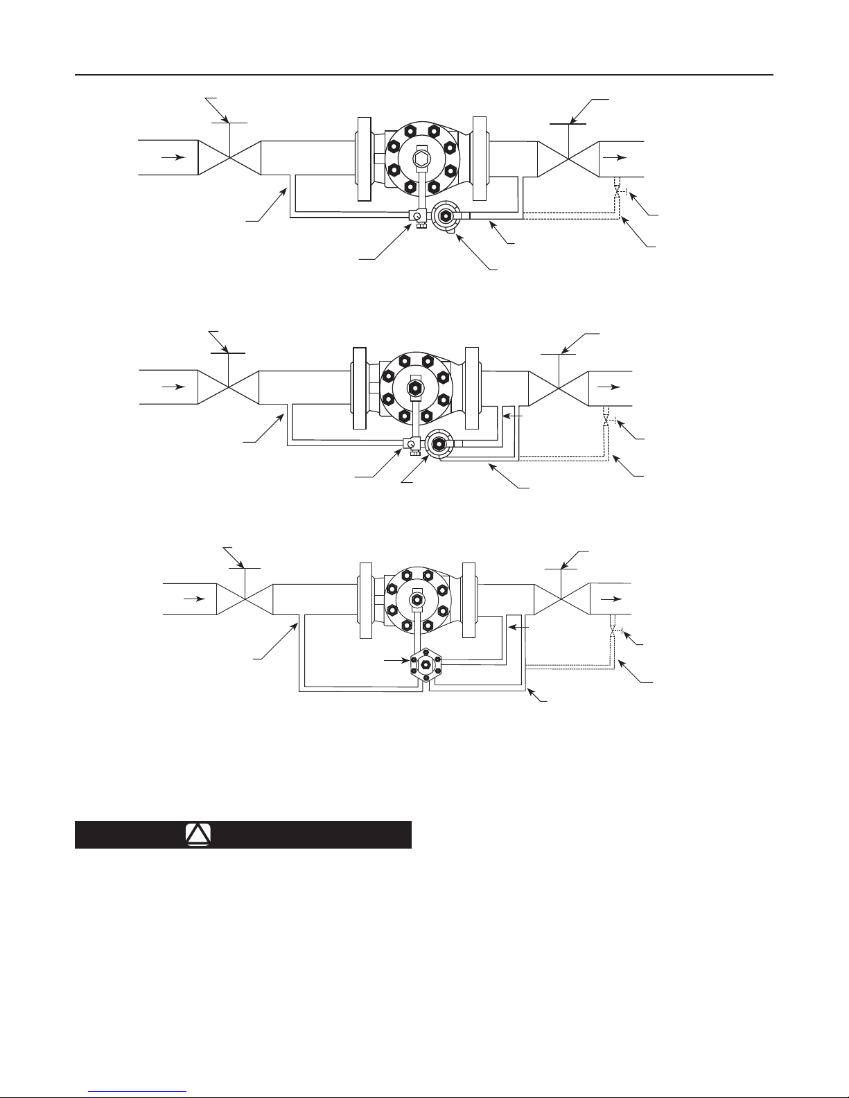
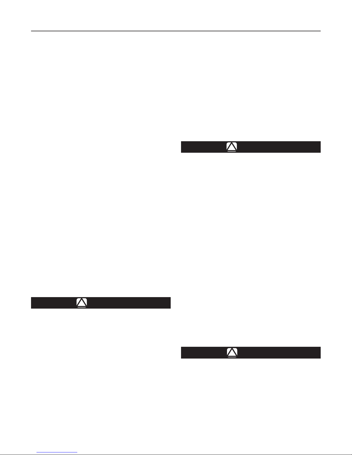
INLET
SUPPLY PRESSURE LINE
B2605_A
INLET
SUPPLY PRESSURE LINE
B2605_B
BLOCK VALVE
CONTROL LINE
RESTRICTOR
161 SERIES SINGLE PILOT INSTALLATION WITH PILOT EXHAUST INTO CONTROL LINE
BLOCK VALVE
RESTRICTOR
161 SERIES SINGLE PILOT INSTALLATION WITH SEPARATE PILOT EXHAUST LINE
161 SERIES
PILOT
161 SERIES PILOT
PILOT
EXHAUST
CONTROL LINE
BLOCK VALVE
BLOCK VALVE
OUTLET
HAND VALVE
ALTERNATE CONTROL LINE
OUTLET
HAND VALVE
ALTERNATE CONTROL LINE
BLOCK VALVE
INLET
SUPPLY PRESSURE LINE
TYPE PRX SINGLE-PILOT INSTALLATION WITH SEPARATE PILOT EXHAUST LINE
Figure 3. Typical Type EZR Single Installation Schematics
Type EZR Installation
WARNING
!
Personal injury, equipment damage or
leakage due to escaping gas or bursting
of pressure-containing parts may result
if this regulator is overpressured or is
installed where service conditions could
exceed the limits given in Specications
section on page 2 or where conditions
exceed any ratings of the adjacent
piping or piping connections.
TYPE PRX PILOT
BLOCK VALVE
OUTLET
PILOT
EXHAUST
CONTROL LINE
HAND VALVE
ALTERNATE CONTROL LINE
To avoid such injury or damage, provide
pressure-relieving or pressure-limiting
devices (as required by the appropriate
code, regulation or standard) to
prevent service conditions from
exceeding limits.
Additionally, physical damage to the
regulator could break the pilot off the
main valve, causing personal injury and
property damage due to escaping gas.
To avoid such injury and damage, install
the regulator in a safe location.
6
Type EZR
All Installations
The robust design of the Type EZR allows this
regulator to be installed indoors or outdoors. When
installed outdoors, the Type EZR does not require
protective housing. This regulator is designed
to withstand the elements. The powder paint
coating protects against minor impacts, abrasions
and corrosion.
When installed indoors, no remote venting is required
except on the pilot spring case. This regulator can
also be installed in a pit that is subject to ooding
by venting the pilot spring case above the maximum
possible ood level so the pilot setting can be
referenced at atmospheric pressure.
1. Only personnel qualied through training and
experience should install, operate and maintain a
regulator. Before installation, make sure that there
is no damage to or debris in the regulator. Also,
make sure that all tubing and piping are clean
and unobstructed.
Note
The Type EZR optional inlet strainer is
intended to prevent occasional large
particles from entering the main valve.
If the gas contains continuous particles,
upstream ltration is recommended.
When using an inlet strainer (key 23), do
not use the shim (key 23) and vice versa.
2. Type EZR regulator may be installed in any
orientation, as long as ow through the regulator
matches the direction of the arrow on the main
valve body. However, for easier maintenance,
install the regulator with the bonnet up.
CAUTION
When installing a Type EZR trim package
in an existing E-body, make sure ow is
up through the center of the cage and
down through the cage slots. In some
cases, correct ow path is achieved
by removing the body from the line
and turning it around. If this is done,
change the ow arrow to indicate the
correct direction. Damage may result
if ow is not in the correct direction.
After assembly, check the regulator for
shutoff and leakage to atmosphere.
Types EZR/399 restricted trim bodies
(NPS 6 x 4, 8 x 4, 8 x 6 and 12 x 6 /
DN 150 x 100, 200 x 100, 200 x 150 and
300 x 150) are different than EW valve
bodies and are not interchangeable.
Install trims only in correct restricted
trim bodies.
3. The standard pilot mounting position is as shown in
Figure 1. Other mounting positions are available.
4. Apply a good grade of pipe compound to the
external pipeline threads for a threaded body or
use suiTable line gaskets for a anged body. When
installing butt weld end connections, remove trim
before welding and make sure to use approved
welding practices. Use approved piping procedures
when installing the regulator.
CAUTION
A regulator may vent some gas to
the atmosphere. In hazardous or
ammable gas service, vented gas may
accumulate and cause personal injury,
death or property damage due to re
or explosion.
Vent a regulator in hazardous gas
service to a remote, safe location away
from air intakes or any hazardous
location. Protect the vent line or
stack opening against condensation
or clogging.
5. A clogged pilot spring case vent may cause the
regulator to function improperly. To prevent plugging
(and to keep the spring case from collecting moisture,
corrosive chemicals or other foreign material) point
the vent down, orient it to the lowest possible point
on the spring case or otherwise protect it. Inspect the
vent regularly to make sure it has not been plugged.
To remotely vent a spring case, remove the vent
and install obstruction-free tubing or piping into the
1/4 NPT vent tapping. Provide protection on a remote
vent by installing a screened vent cap onto the
remote end of the vent pipe. The 161AY Series pilot
has a vent restriction (key 55, Figure 20) to enhance
low ow stability. Do not remove this restriction.
WARNING
!
To avoid freeze-up because of pressure
drop and moisture in the gas, use
antifreeze practices, such as heating the
supply gas or adding a de-icing agent to
the supply gas.
7
Type EZR
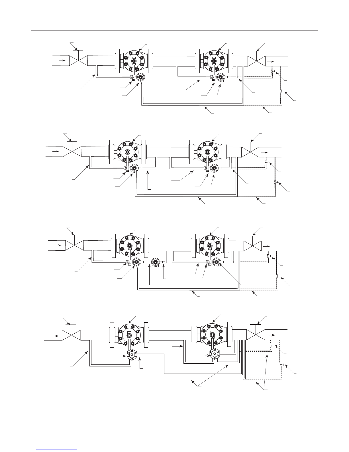
INLET
SUPPLY
PRESSURE LINE
INLET
SUPPLY
PRESSURE LINE
BLOCK VALVE
161 SERIES PILOT
RESTRICTOR
UPSTREAM REGULATOR
SUPPLY
PRESSURE
LINE
RESTRICTOR
DOWNSTREAM
REGULATOR
161 SERIES
PILOT
CONTROL LINE
BLOCK VALVE
CONTROL
LINE
ALTERNATE
CONTROL LINE
161 SERIES WIDE-OPEN MONITORING SYSTEM INSTALLATION
B2605_C
BLOCK VALVE
161 SERIES PILOT
RESTRICTOR
UPSTREAM REGULATOR
SUPPLY
PRESSURE
LINE
PILOT
EXHAUST
RESTRICTOR
DOWNSTREAM
REGULATOR
161 SERIES
PILOT
CONTROL LINE
BLOCK VALVE
CONTROL
LINE
OUTLET
ALTERNATE
CONTROL LINE
161 SERIES WIDE-OPEN MONITORING SYSTEM INSTALLATION WITH PILOT EXHAUST TO INTERMEDIATE PRESSURE
OUTLET
HAND VALVE
HAND VALVE
HAND
VALVE
HAND
VALVE
INLET
SUPPLY
PRESSURE LINE
B2605_D
INLET
SUPPLY
PRESSURE LINE
BLOCK VALVE BLOCK VALVE
RESTRICTOR
161 SERIES
MONITOR PILOT
MONITOR REGULATOR
CONTROL LINE
161 SERIES WORKING PILOT
SUPPLY
PRESSURE
LINE
CONTROL LINE
WORKING
REGULATOR
RESTRICTOR
161 SERIES
PILOT
ALTERNATE
CONTROL LINE
OUTLET
161 SERIES WORKING MONITORING SYSTEM INSTALLATION
BLOCK VALVE
TYPE PRX
PILOT
UPSTREAM REGULATOR
SUPPLY
PRESSURE
LINE
PILOT
EXHAUST
TYPE PRX
PILOT
CONTROL LINE
DOWNSTREAM
REGULATOR
BLOCK VALVE
ALTERNATE
CONTROL LINE
TYPE PRX WIDE-OPEN MONITORING SYSTEM INSTALLATION
Figure 4. Typical Type EZR Monitoring System Installation Schematics
HAND VALVE
OUTLET
HAND
VALVE
HAND
VALVE
HAND
VALVE
8
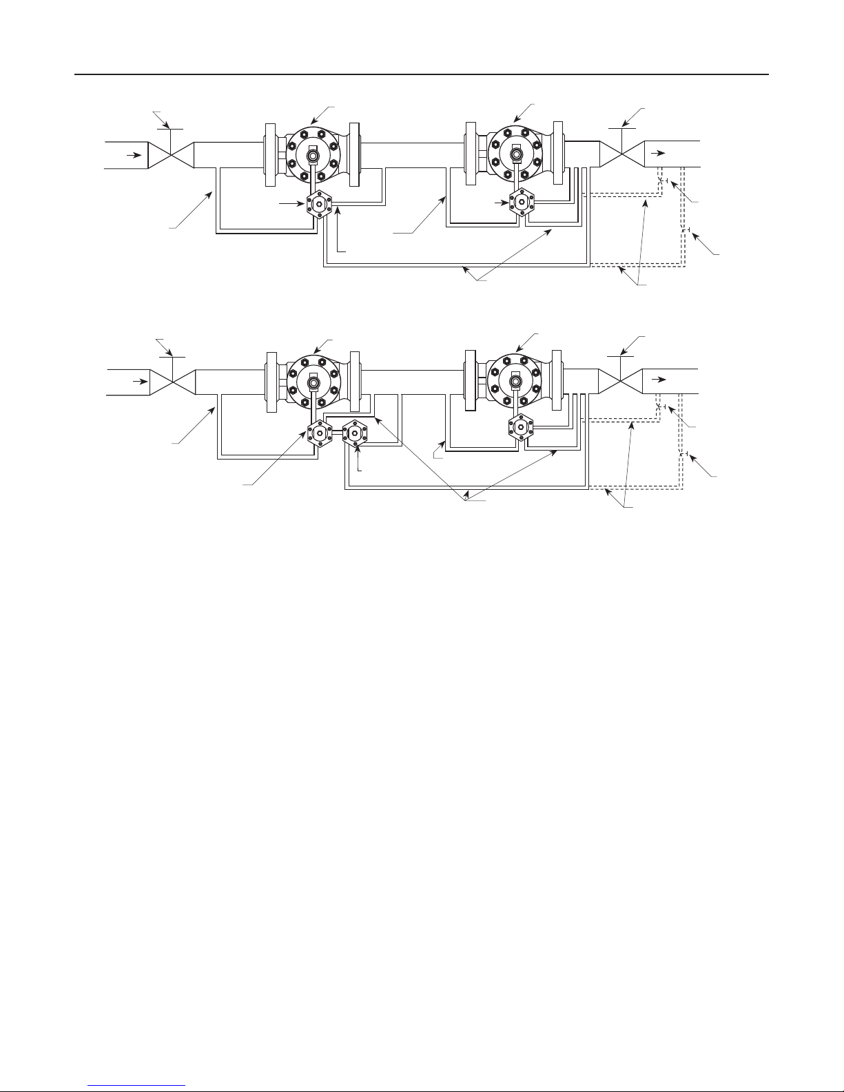
Type EZR
INLET
SUPPLY
PRESSURE LINE
TYPE PRX WIDE-OPEN MONITORING SYSTEM INSTALLATION WITH PILOT EXHAUST TO INTERMEDIATE PRESSURE
INLET
SUPPLY
PRESSURE LINE
(1) PLUGGED
BLOCK VALVE
BLOCK VALVE
TYPE PRX-120
WORKING PILOT
Figure 4. Typical Type EZR Monitoring System Installation Schematics (continued)
TYPE PRX
PILOT
UPSTREAM REGULATOR
TYPE PRX
SUPPLY
PRESSURE
LINE
PILOT
EXHAUST
MONITOR REGULATOR
A
L
B
(1)
L
S
A
S
TYPE PRX WORKING MONITOR SYSTEM INSTALLATION
B
TYPE PRX-125
MONITOR PILOT
PILOT
SUPPLY
PRESSURE
LINE
CONTROL LINE
CONTROL LINE
DOWNSTREAM
REGULATOR
WORKING
REGULATOR
BLOCK VALVE
OUTLET
ALTERNATE
CONTROL LINE
BLOCK VALVE
OUTLET
ALTERNATE
CONTROL LINE
HAND
VALVE
HAND
VALVE
HAND
VALVE
HAND
VALVE
6. As shown in Figure 3, run a supply pressure line
from the upstream pipeline to the restrictor inlet
(use 3/8 NPT outer diameter tubing or larger).
Install a Type 252 pilot supply lter upstream of
the restrictor, if needed, to keep the supply source
from clogging the restrictor or pilot. Inspect and
clean this lter regularly to make sure it has not
been plugged.
7. Install a downstream pressure control line (as
shown in the appropriate view of Figure 3) to the
pilot control line connection. Connect the other
end of the control line at a minimum of 8 to 10 pipe
diameters downstream of the regulator in a straight
run of pipe. Do not place a control line connection in
a turbulent area, such as in or directly downstream
of a swage or elbow. Signicant restrictions in
the control line can prevent proper pressure
registration. When using a hand valve, it should be
a full ow valve, such as a full port ball valve. With
a Type 161EBM, 161EBHM or 161AYM pilot or a
PRX Series pilot, run a downstream exhaust bleed
line to the downstream bleed line connection in the
pilot body assembly.
8. Good piping practices usually require swaging up
to larger downstream piping to obtain reasonable
downstream uid velocity.
Wide-Open Monitor Installations
1. Follow the procedures in the All Installations
section and then continue with step 2 of
this section.
2. Pilot supply for the downstream monitoring regulator
must be obtained between the two regulators as
shown in Figure 4. For sizing purposes, add the
minimum differential pressure for each regulator
together to establish the required pressure drop
across the station.
3. In a wide-open Type EZR monitoring system, system
lockup will be that of the worker regulator on both an
upstream monitor when the upstream pilot exhaust is
piped to the intermediate pressure and a downstream
monitor with upstream pilot exhaust piped to either
intermediate pressure or outlet pressure. With these
congurations, the diaphragm of the monitor regulator
will change position with every load change. On an
upstream monitor with the upstream pilot exhaust
piped to downstream, lockup will occur at the
monitor’s setpoint and the diaphragm of the monitor
regulator will be fully open during normal conditions.
9
Type EZR
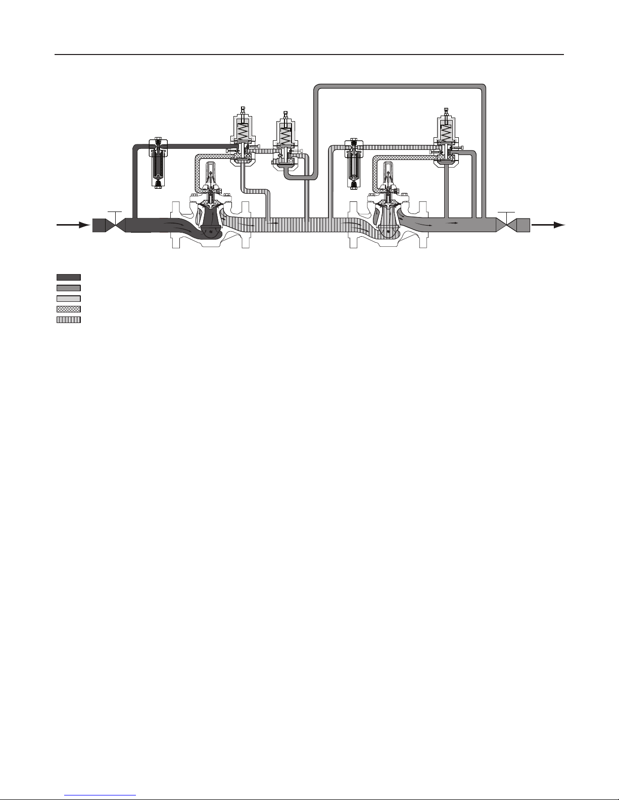
TYPE PRX/120
M1001_05/2016
INLET PRESSURE
OUTLET PRESSURE
ATMOSPHERIC PRESSURE
LOADING PRESSURE
INTERMEDIATE PRESSURE
INLET
FILTER
PILOT
S
L
A
TYPE PRX:
S- SUPPLY PORT
B- BLEED PORT
L- LOADING PORT
A - SENSING PORT
Figure 5. Type EZR-PRX-PRX Working Monitor Schematic
TYPE PRX/125
PILOT
B
S
A
INTERMEDIATE
Working Monitor Installations
On working monitor installations, the working monitor
regulator is always upstream and acts as a rst-stage
regulator through the working pilot during normal
operation. This arrangement allows the working
monitor’s performance to be observed at all times.
Then, should the second-stage regulator fail open,
the working monitor regulator assumes the entire
pressure reduction function of the system through the
monitoring pilot.
Use the following procedure when installing a working
monitor system.
1. Follow the procedures in the All Installations
section and then continue with step 2 of
this section.
2. Pilot supply pressure for the downstream
Type EZR regulator must be made directly
upstream of the Type EZR using
intermediate pressure.
3. Table 9 gives the spread between normal
distribution pressure and the minimum pressure at
which the monitor pilot can be set to take over if
the working regulator fails open.
4. Table 4 shows the minimum differential pressure
requirements across an individual regulator.
Because this application uses a rst-stage
TYPE PRX/120
PILOT
FILTER
B
S
L
B
A
OUTLET
and second-stage pressure reduction, add the
minimum differential pressure for each regulator
together to establish the required pressure drop
across the station. Do not exceed maximum pilot
ratings given in Table 3.
For Type PRX Working Monitor
As shown in Figure 5, run a supply pressure line
(use 3/8 NPT outer diameter tubing or larger) from the
upstream pipeline to the inlet (Port S) of the upstream
Type PRX-120 pilot. Install a Type 252 pilot supply
lter upstream of the pilot, if needed, to keep the
supply source from clogging the restrictor in the pilot.
Inspect and clean this lter regularly to make sure it
has not been plugged.
Connect the loading port (Port L) of the upstream
Type PRX-120 pilot to the bonnet of the upstream
Type EZR regulator. Connect the “B” port of the upstream
Type PRX-120 pilot to the “S” port of the upstream
Type PRX-125 pilot. Connect the “A” port (located on the
underside of the pilot) of the upstream Type PRX-120 pilot
to the intermediate pressure between the rst and second
Type EZR regulators as shown in Figure 5.
The “L” port of the upstream Type PRX-125 pilot is
plugged. Connect the “B” port of upstream
Type PRX-125 pilot to the intermediate pressure
between the rst and second Type EZR regulators.
10
Connect the “A” port of upstream Type PRX-125 pilot
downstream of both regulators.
The pilot supply pressure connection for the
downstream Type EZR regulator must be directly
upstream of the Type EZR using intermediate pressure
and connected to the “S” port of the downstream
Type PRX-120. Install a Type 252 pilot supply lter
upstream of the pilot, if needed, to keep the supply
source from clogging the restrictor in the pilot. Inspect
and clean this lter regularly to make sure it has not
been plugged. Connect the loading port (Port L) of the
downstream Type PRX-120 pilot to the bonnet of the
downstream Type EZR regulator. Connect the “A” and
“B” ports of the downstream Type PRX-120 pilot to
downstream pressure.
Startup and Adjustment
Note
Table 10 shows the maximum inlet
and differential pressures for specic
constructions. Use pressure gauges to
monitor inlet pressure, outlet pressure
and any intermediate pressure
during startup.
CAUTION
To prevent damage to the Type PRX pilot
during startup, the sense and bleed lines
of the Type PRX should be located on the
same side of the downstream block valve.
Keep sense and bleed lines separate.
Startup for Both Single-Regulator and
Monitoring Installations
1. Make sure all block and vent valves are closed.
2. Back out the pilot adjusting screw(s).
3. For easy initial startup, set the restrictor to the “8”
position. For future startups, the restrictor can be
left in the desired run position.
4. SLOWLY OPEN the valves in the following order:
a. Pilot supply and control line valve(s), if used
b. Inlet block valve
c. Outlet block valve
5. For a 161 Series pilot with Type 112 restrictor,
turn the restrictor(s) to position “2” or to the
desired run position. For a PRX Series pilot, turn
the restrictor screw 1 turn counterclockwise from
fully seated (turn restrictor fully clockwise then
1 turn counterclockwise) and the damper screw
fully counterclockwise.
Type EZR
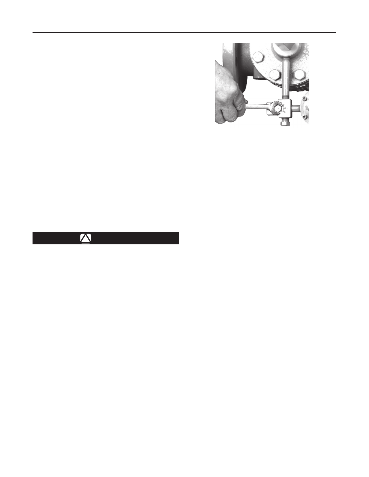
W4559_1
Figure 6. Restrictor Adjustment
6. For a single regulator, set the pilot to the desired
outlet (control) pressure according to the pilot
adjustment procedure.
For a wide-open downstream monitor
installation, adjust the upstream working pilot until
intermediate pressure is higher than the desired
setpoint of the monitor pilot. Adjust the downstream
monitoring pilot to the desired monitoring takeover
pressure. Reduce the upstream pilot to the normal
outlet pressure setting.
For a wide-open upstream monitor installation,
adjust the downstream working pilot to a setpoint
higher than the setpoint of the monitor pilot.
Adjust the upstream monitoring pilot to the desired
monitor takeover pressure. Reduce the downstream
pilot setting to normal outlet pressure setting.
For a working monitor installation, turn out the
adjusting screw of the downstream pilot, removing
spring tension. Adjust the upstream working pilot
to the desired intermediate pressure setting.
Turn out the adjusting screw of the upstream
monitor pilot, removing spring tension. Turn in
the adjusting screw of the downstream pilot.
Adjust the upstream monitor pilot to the desired
setpoint taking into account the guidelines shown
in Table 9. Establish nal desired downstream
pressure by adjusting the downstream pilot.
Pilot Adjustment
For 161 Series pilots, remove the pilot closing cap
(key 16, Figure 19 or key 22, Figure 20) and, on
161EB Series only, loosen the locknut (key 12,
Figure 19). Turn the adjusting screw (key 11,
Figure 19 or key 35, Figure 20) into the spring case
(key 2, Figure 19 or key 3, Figure 20) to increase the
downstream pressure. Turn the adjusting screw out of
the spring case to decrease the downstream pressure.
11
Type EZR
Table 5. 161EB Series Pilot Adjustment Recommendations
PILOT TYPE
161EB Series Pilots Restrictor Setting of “5” or greater
Note: Higher Type 112 restrictor settings will increase proportional band. Adjustment of the Type 112 restrictor will also cause a shift in setpoint. Setpoint should be checked and adjusted
following restrictor setting adjustment.
RECOMMENDED TYPE 112 RESTRICTOR
SETTINGS FOR LOW FLOW OPERATION
Table 6. Type 161AY/161AYM Pilot Adjustment Recommendations
PILOT TYPE
161AY Series Pilots Restrictor Setting of “5” or greater
Note: Higher Type 112 restrictor settings will increase proportional band. Adjustment of the Type 112 restrictor will also cause a shift in setpoint. Setpoint should be checked and adjusted
following restrictor setting adjustment.
RECOMMENDED TYPE 112
RESTRICTOR SETTINGS FOR LOW
FLOW OPERATION
RECOMMENDED ORIFICE SIZE(S)
FOR LOW FLOW OPERATION
3/32 or 1/8 in. / 2.38 or 3.18 mm
(3/32 in. / 2.38 mm is standard)
Table 7. Type PRX Pilot Adjustment Recommendations
TYPE 112 RESTRICTOR SETTINGS TO AVOID
AT LOW FLOW
Avoid restrictor setting of “2” or less if continuous
ows are expected to be less than 5%
of maximum capacity
TYPE 112 RESTRICTOR SETTINGS
AND ORIFICE SIZES TO AVOID AT
LOW FLOW
Avoid restrictor setting of “2” or less if
continuous ows are expected to be
less than 5% of maximum capacity
PILOT TYPE
PRX/120 and PRX/120-AP Series
Note: Counterclockwise adjustment of the Type PRX restrictor screw will increase proportional band. Adjustment of the restrictor screw will also cause a shift in setpoint. Setpoint should
be checked and adjusted following restrictor screw adjustment.
RECOMMENDED TYPE PRX RESTRICTOR AND DAMPER
SCREW SETTINGS FOR LOW FLOW OPERATION
Restrictor Screw
- 1 turn out (counterclockwise) from fully seated for most
low ows
- 2-1/2 turns out (for ows less than
5% of maximum)
Damper Screw
- Fully out (counterclockwise) from seated for most
low ows
- One turn out (for ows less than 5% of maximum)
For PRX Series pilots (Figure 26), loosen locknut
(key 2) and turn the adjusting screw into the spring case
to increase (or out of the spring case to decrease) the
downstream pressure. When the required downstream
pressure is maintained for several minutes, tighten the
locknut to lock the adjusting screw in position
and replace the pilot closing cap.
The Restrictor and Damper screws on the PRX Series
pilot control the regulator’s proportional band (droop)
and speed of response. Table 7 includes the appropriate
settings for low ow operation. For additional tuning
follow the steps outlined below:
1. Start with the restrictor screw 1 turn
counterclockwise from fully seated (turn restrictor
fully clockwise then 1 turn counterclockwise) and
the damper screw fully counterclockwise.
2. Turn damper screw clockwise until desired
performance is achieved. This reduces the ow
path of the damper. If the damper becomes fully
seated (no longer able to turn clockwise) and the
desired performance has not been achieved, return
the damper screw to the fully counterclockwise position.
The damper screw should not be left in
the fully seated position, as it will lock
the regulator in last position which could
cause incorrect pressure regulation.
3. Turn the restrictor screw an additional turn
counterclockwise from fully seated. This increases
the ow path of the restrictor. If additional tuning
is required, repeat step 2. Follow this method until
desired performance is achieved.
Type 112 Restrictor Adjustment
The Type 112 restrictor controls the regulator’s
proportional band (droop) and speed of response.
The restrictor can be used to ne tune the regulator
for maximum performance by decreasing the restrictor
setting for tighter control (increased opening speed,
decreased closing speed); or increasing the restrictor
setting for maximum stability (decreased opening speed,
increased closing speed). A lower setting also provides a
TYPE PRX RESTRICTOR AND DAMPER SCREW
SETTINGS TO AVOID AT LOW FLOW
Restrictor Screw
- Fully seated (clockwise) or full out
(counterclockwise)
WARNING
!
Damper Screw
- Full in (clockwise)
narrower proportional band for better accuracy.
12
 Loading...