

Page 1
Instruction Manual
D103319X012
May 2009
Lever-Lock Handlever Actuator
Fisherr Lever-Lock Handlever Actuators
for POSI-SEALt A81 Rotary Valves
Contents
Introduction 1.................................
Scope of Manual 1.........................
Description 1..............................
Specifications 2............................
Installation
Ordering Replacements 5.....................
Introduction
Scope of Manual
This instruction manual includes installation,
maintenance, and parts information for the Fisher
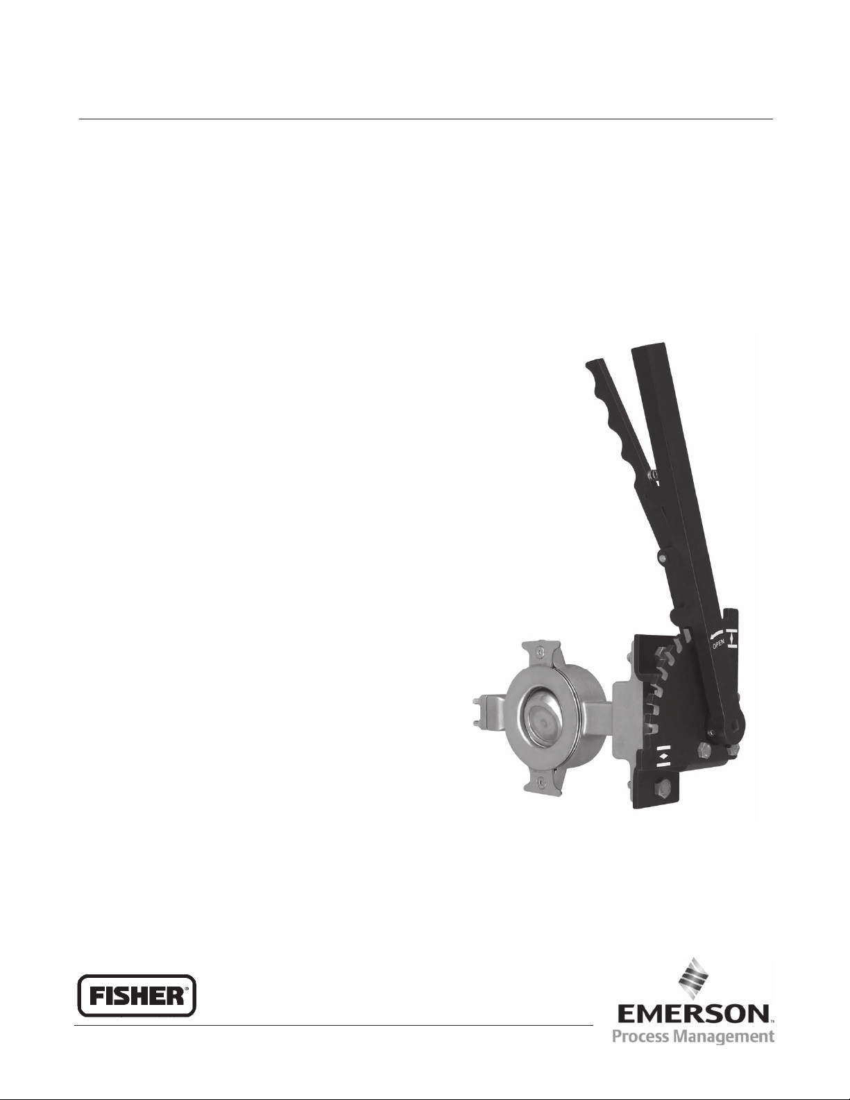
Lever-Lock handlever actuator (figure 1). Refer to
separate instruction manuals for information
covering the control valves.
3..................................
Do not install, operate, or maintain a Lever-Lock
actuator without being fully trained and qualified in
valve, actuator, and accessory installation,
operation, and maintenance. To avoid personal
injury or property damage, it is important to carefully
read, understand, and follow all the contents of this
manual, including all safety cautions and warnings. If
you have any questions about these instructions,
contact your Emerson Process Management sales
office before proceeding.
Description
The Lever-Lock handlever is used for reliable
manual operation of DN 50 through 150 (NPS 2
through 6) Fisher A81 high-performance butterfly
valves. Spring-loading secures the handlever in the
notched quadrant plate (figure 2), allowing the valve
disk to be locked in intermediate positions.
Additionally, the handlever can be locked with a
user-supplied padlock with 4.8 to 5.2 mm
(3/16 to 13/64 inch) shackle to prevent accidental or
unauthorized adjustment (see figures 3 and 4).
W9585
Figure 1. Fisher Lever-Lock Handlever Actuator
Mounted on Valve
www.Fisher.com
Page 2
Instruction Manual
Lever-Lock Handlever Actuator
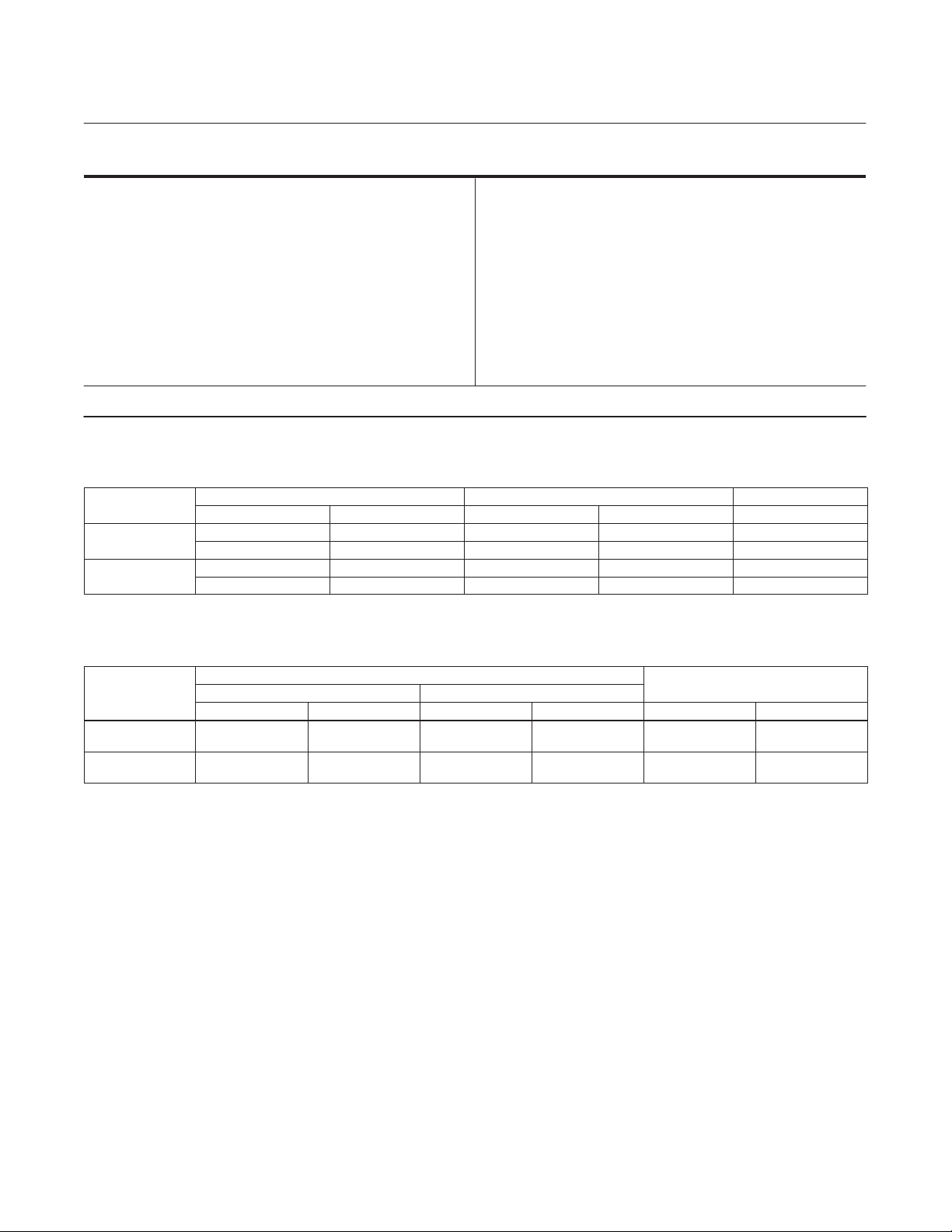
Table 1. Specifications
Lever-Lock Handlever Actuator Sizes
See table 2
Valve Compatibility
Mounts on A81 valves per table 2
Maximum torque Output
See table 3
1. The pressure/temperature limits in this manual, and any applicable code or standard limitation, should not be exceeded.
Table 2. Fisher A81 Valve / Lever-Lock Handlever Compatibility
HANDLEVER
ACTUATOR SIZE
I
II
VALVE SIZE SHAFT SIZE SQUARE SIZE
DN NPS mm Inches mm
50 2 12.7 1/2 9
80 3 15.9 5/8 11
100 4 19.1 3/4 14
150 6 25.4 1 17
Handlever Length
Maximum of 432 mm (17 inches). See figure 2
and table 4
Construction Materials
Handle, quadrant plate, lever, and mounting
bracket are all steel materials. Spring, set screws,
and fasteners are stainless steel
Dimension and Approximate Weights
See figure 2 and table 4
May 2009
VALVE DISK
POSITION
0 Degrees
(Breakout Torque)
All Other Angles
(Dynamic Torque)
Table 3. Maximum Allowable Torques and Handlever Force Requirements
MAXIMUM TORQUE
Size I Size II
NSm InSLb NSm InSLb
119 1050 164 1450 423 95
47 420 70 620 178 40
HANDLEVER FORCE REQUIRED
N Lbf
2
Page 3
Instruction Manual
May 2009
Installation
The Lever-Lock handlever actuator is normally
shipped mounted on the valve at the factory. If the
handlever was ordered separately, install the
handlever on the valve by following the instructions
in this section.
WARNING
Sudden or unexpected movement of
the handle can result from unbalanced
flow forces. Firmly grip the handlever
and ensure stable footing when
operating the handlever to avoid
personal injury or property damage.
Installing the Handlever
Orientation
Mount the Lever-Lock bracket assembly, less the
handle, to the valve body. The handle is
perpendicular to the pipeline when the valve is in the
shut position. Rotation of the lever/valve shaft in the
counter-clockwise direction will open the valve.
Attach the Lever-Lock Handlever actuator to the
valve in this orientation but do not fully tighten
Lever-Lock Handlever Actuator
(torque) the bracket to valve bolting until after the
zeroing process below.
Handle assembly
Place the handle and lever assembly on the valve
shaft with the valve closed. Squeeze the lever to
compress the spring, position the lever over the
notch indicating the closed position, and slide the
square cutout portion of the handle over the valve
shaft as far as it will go. Maintain at least a 0.8 mm
(1/32 inch) gap between the handle and the plate, so
the handle doesn’t rub on the plate during operation.
Torque the two hex socket set screws against the
shaft to 2.7 NSm (24 inSlbf).
Zeroing
After tightening the set screws, check the orientation
of the disk relative to the body seal retainer. Place a
straight edge on the seal retainer which spans the
valve opening. Visually check to ensure there is
equal space (within 0.8 mm [1/32 inch]) between this
straight edge and the top and bottom of the disk to
ensure the valve is fully engaged in the seal. To
adjust this position, rotate the bracket within the
clearance of the mounting bolt holes between the
valve body and bracket. Once there is equal
distance between the disk and the straight edge,
tighten the mounting bolts to 115 NSm (88 ftSlbf).
After tightening, recheck disk position at shutoff to
ensure nothing shifted during the tightening process.
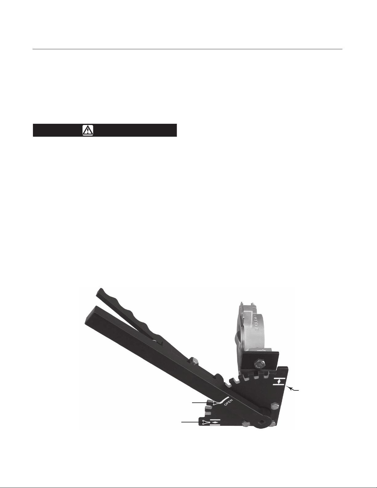
W9583
“CLOSED”
MARK
“OPEN” MARK ON HANDLE
“OPEN” MARK
Figure 2. Fisher Lever-Lock Handlever Actuator for A81 Valve (Open/Closed Marks)
3
Page 4

Instruction Manual
Lever-Lock Handlever Actuator
Maintenance
Handlever parts are subject to normal
wear/corrosion and must be inspected and replaced
when necessary. The frequency of inspection and
replacement depends on the severity of service
conditions.
WARNING
Avoid personal injury or damage to
property from sudden release of
pressure or uncontrolled process fluid.
Before starting disassembly:
D Do not remove the actuator from
the valve while the valve is still
pressurized.
D Always wear protective gloves,
clothing, and eyewear when
performing any maintenance
operations to avoid personal injury.
May 2009
D Use bypass valves or completely
shut off the process to isolate the
valve from process pressure. Relieve
process pressure on both sides of the
valve. Drain the process media from
either side of the valve.
D Use lock-out procedures to be
sure that the above measures stay in
effect while you work on the
equipment.
D The valve packing box may
contain process fluids that are
pressurized, even when the valve has
been removed from the pipeline.
Process fluids may spray out under
pressure when removing the packing
hardware or packing rings, or when
loosening the packing box pipe plug.
D Check with your process or safety
engineer for any additional measures
that must be taken to protect against
process media.
4
GG00568_DIS_1
LOCATION FOR USER-SUPPLIED
PADLOCK WITH 4.8 to 5.2mm
(3/16 to 13/64 INCH) SHACKLE
Figure 3. Fisher Lever-Lock Handlever Actuator for A81 Valve (Showing Padlock Location)
Page 5

Instruction Manual
May 2009
Ordering Replacements
When corresponding with your Emerson Process
Management sales office about this equipment,
always mention the valve serial number. It is
recommended that complete assemblies are
considered for replacements to ensure the latest
version of the product is supplied.
WARNING
Use only genuine Fisher replacement
parts. Components that are not
supplied by Emerson Process
Management should not, under any
Lever-Lock Handlever Actuator
circumstances, be used in any Fisher
valve, because they may void your
warranty, might adversely affect the
performance of the valve, and could
cause personal injury and property
damage.
Note
Neither Emerson, Emerson Process
Management, nor any of their affiliated
entities assumes responsibility for the
selection, use, or maintenance of any
product. Responsibility for the
selection, use, and maintenance of any
product remains with the purchaser
and end user.
5
Page 6

Instruction Manual
Lever-Lock Handlever Actuator
HANDLE
SET SCREWS
SPRING
LEVER
May 2009
PLATE
BRACKET
GG03237_1
VALVE
Figure 4. Fisher Lever-Lock Handlever Actuator for A81 Valve (fully closed valve position shown)
Table 4. Dimensions and Weights
VALVE SIZE M L WEIGHT
DN NPS mm Inch mm Inch kg lbs
50 2 315 12.4 85 3.35 2.72 3
80 3 315 12.4 85 3.35 2.72 3
100 4 432 17.0 103 4.06 3.63 4
150 6 432 17.0 103 4.06 3.63 4
6
Page 7

Instruction Manual
May 2009
Lever-Lock Handlever Actuator
7
Page 8

Instruction Manual
Lever-Lock Handlever Actuator
May 2009
Fisher and POSI-SEAL are marks owned by one of the companies in the Emerson Process Management business division of Emerson Electric Co.
Emerson Process Management, Emerson, and the Emerson logo are trademarks and service marks of Emerson Electric Co. All other marks are
the property of their respective owners.
The contents of this publication are presented for informational purposes only, and while every effort has been made to ensure their accuracy, they
are not to be construed as warranties or guarantees, express or implied, regarding the products or services described herein or their use or
applicability. All sales are governed by our terms and conditions, which are available upon request. We reserve the right to modify or improve the
designs or specifications of such products at any time without notice. Neither Emerson, Emerson Process Management, nor any of their affiliated
entities assumes responsibility for the selection, use or maintenance of any product. Responsibility for proper selection, use, and maintenance of
any product remains solely with the purchaser and end-user.
Emerson Process Management
Marshalltown, Iowa 50158 USA
Sorocaba, 18087 Brazil
Chatham, Kent ME4 4QZ UK
Dubai, United Arab Emirates
Singapore 128461 Singapore
www.Fisher.com
8
EFisher Controls International LLC 2009; All Rights Reserved
 Loading...