

Page 1
LCP100 Local Control Panel
D103604X012
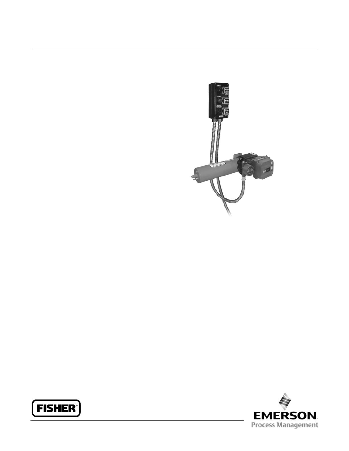
Fisherr LCP100 Local Control Panel
The LCP100 local control panel is used in conjunction
with the FIELDVUE™ DVC6200 SIS digital valve
controller to manually open, close, or test a safety
shutdown valve. The LCP100 has three protected
pushbuttons to allow the user to open, close or test
the safety valve. There are also three lights to visually
indicate if the valve is open, closed, or locked in safety
and ready for reset.
Features
Reliability
n Rugged Enclosure—The filled polyester enclosure,
encapsulated electronics, pushbuttons, and lights
are designed to withstand harsh industrial
environments.
n Proof Testing—The open and close pushbuttons
provide a means to manually perform an offline full
stroke test to help identify dangerous undetected
failures.
n Partial Valve Stroke Test—The test pushbutton
provides a means to manually perform an online
partial stroke test to help improve the diagnostic
coverage factor.
Safety
n Manual Reset—After a safety demand, the DVC6200
SIS will remain locked in the safe state. The manual
reset pushbutton provides user control over when
the valve can return to the normal operating state.
n Lockable Pushbutton Covers—Each pushbutton can
be locked to prevent unauthorized access to the
safety valve operation.
n Safety Certification—The LCP100 contribution to
failure rates is documented in the DVC6200 SIS
safety manual.
X0247
Ease of Use
n Loop vs. External Power—The LCP100 can be
powered by the same loop as the DVC6200 SIS or
independently powered by a 24 VDC source.
n Simple Configuration—The DVC6200 SIS setup
wizard automatically configures the LCP100
functions.
Value
n Visual Indication—The LCP100 can be mounted
remote from the valve in an easily accessible
location to view the status and perform periodic
testing.
n Reduce I/O Count—The LCP100 combines
open/closed/readytoreset lights and open/close
pushbuttons into a single field enclosure, thus
eliminating 3 discrete out (DO) and 2 discrete in (DI)
channels from the logic solver.
FISHER LCP100 LOCAL CONTROL
PANEL, WITH FIELDVUE DVC6200 SIS
DIGITAL VALVE CONTROLLER AND
Product Bulletin
November 2013
BETTIS™
ACTUATOR
62.1:LCP100
www.Fisher.com
Page 2

Product Bulletin
62.1:LCP100
November 2013
Specifications
LCP100 Local Control Panel
D103604X012
Power Options (switch selectable)
J External: 24 VDC +/- 10% @ 50 mA maximum
Wiring
14 to 26 AWG
continuous current (100 mA maximum inrush)
J Loop: 8-20 mA (LCP100 and DVC6200 SIS
combined)
Temperature Limits
(1)
-40 to 65_C (-40 to 149_F)
Electrical Installation
Wire connections are polarity sensitive
Installation Orientation
Wiring entrance must be pointed down for
self-draining
Maximum distance between LCP100 and
DVC6200 SIS digital valve controller
Cable length is limited by maximum cable
capacitance of 100,000 pF
(2)
. Typical 314 meters
(1030 feet) with 18 AWG shielded Audio, Control
and Instrumentation Cable
Pushbuttons
Protected with lockable covers
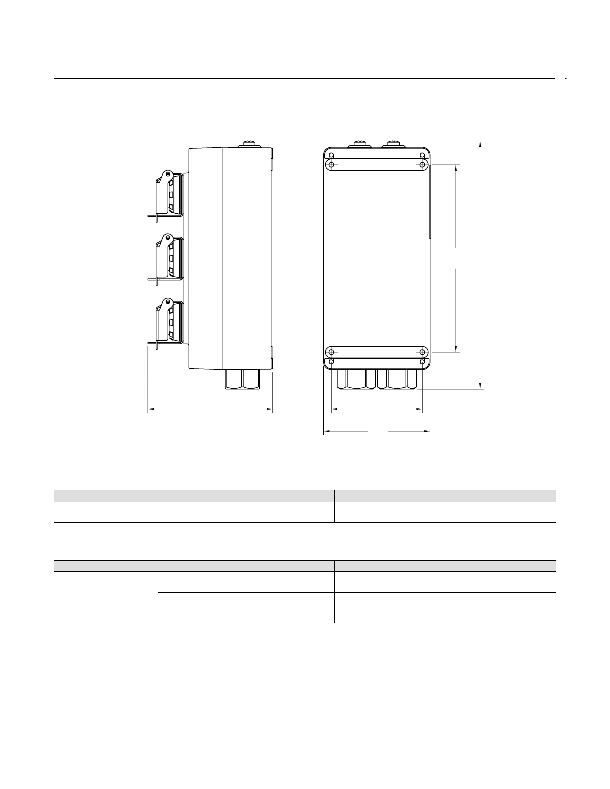
Dimensions
253.1 mm (10 inches) long by 109.5 mm (4.3 inches)
wide by 127.8 mm (5 inches) deep. See figure 1.
Electrical Classification
CSA— Ex em IIC T4
Suitable for Zone 1 and Zone 2 locations
Construction Materials
Housing material: filled polyester
ATEX— Ex e mb [ib] IIC T4 Gb
Suitable for Zone 1 and Zone 2 locations
Ex ic IIC T4 Gc
Approximate Weight
2.2 kg (4.9 lbs)
Suitable for Zone 2 locations
IECEx— Ex e mb [ib] IIC T4
Suitable for Zone 1 and Zone 2 locations
Ex ic IIC T4 Gc
Suitable for Zone 2 locations
Refer to table 1 and 2 for specific approval
information
Lights
Green: Solid when the valve is at its normal operating
position, and loop current is normal. Flashing when
the valve is not at its normal operating position, and
loop current is normal.
Red: Solid when the valve is at its Fail Safe State and
loop current is tripped. Flashing when valve is not at
Electrical Housing:
IP66
its Fail Safe State and loop current is tripped.
Yellow (Ready-to-Reset): Solid when the valve is
latched in the trip position, and loop current is
normal.
Electromagnetic Interference (EMI)
Meets EN 61326-1 (First Edition)
Immunity—Industrial locations per Table 2 of
EN 61326-1 Standard. Performance is
shown in table 3 below.
Emissions—Class A
ISM equipment rating: Group 1, Class A
Connections
Conduit:
1. The pressure/temperature limits in this document and any other applicable code or standard should not be exceeded.
2. DVC6000 SIS: Cable length is limited by maximum cable capacitance of 18000 pF.
J 3/4 NPT or J M20
Pushbuttons
Green: After an emergency demand— commands the
valve to its normal position only after control current
is restored (manual reset).
Red: Always commands the valve to its Fail Safe State
regardless of the control current.
Black: Commands the configured partial stroke test.
Can be overridden by the Close button, Open button,
or Emergency Demand.
2
Page 3
LCP100 Local Control Panel
D103604X012
Figure 1. Dimensions
Product Bulletin
62.1:LCP100
November 2013
194
(7.6)
257
(10.1)
129
(5.1)
E1077-1
94
(3.7)
110
(4.3)
Table 1. Hazardous Area Classifications for Fisher LCP100—CSA (Canada)
Certification Body Certification Obtained Entity Rating Temperature Code Enclosure Rating
CSA
Zone
Ex em IIC T4
- - - T4 (Tamb ≤ 65_C) IP66
Table 2. Hazardous Area Classifications for Fisher LCP100—ATEX / IECEx
Certification Certification Obtained Entity Rating Temperature Code Enclosure Rating
ATEX / IECEx
Zone
Ex e mb [ib] IIC T4 Gb
Zone
Ex ic IIC T4 Gc
Ui = 27 VDC
Ci = 1.1 nF
Li = 0
- - - T4 (Tamb ≤ 65_C) IP66
T4 (Tamb ≤ 65_C) IP66
mm
(INCH)
3
Page 4

Product Bulletin
62.1:LCP100
November 2013
Table 3. Electromagnetic Immunity Performance for Fisher LCP100
Port Phenomenon Basic Standard Test Level
Electrostatic discharge (ESD) IEC 61000-4-2
Enclosure
Radiated EM field IEC 61000-4-3
Burst (fast transients) IEC 61000-4-4
I/O signal/control
Specification limit = ±1% of span
1. A = No degradation during testing. B = Temporary degradation during testing, but is self-recovering.
Surge IEC 61000-4-5
Conducted RF IEC 61000-4-6 150 kHz to 80 MHz at 3 Vrms with 1 kHz AM at 80% A
$4 kV contact
$8 kV air
80 to 1000 MHz @ 10V/m with 1 kHz AM at 80%
1400 to 2000 MHz @ 3V/m with 1 kHz AM at 80%
2000 to 2700 MHz @ 1V/m with 1 kHz AM at 80%
$1 kV, I/O lines
$2 kV, DC power lines
$1 kV, I/O lines
$2 kV, DC power lines)
LCP100 Local Control Panel
D103604X012
Performance
Criteria
A
A
A
A
(1)
Neither Emerson, Emerson Process Management, nor any of their affiliated entities assumes responsibility for the selection, use or maintenance
of any product. Responsibility for proper selection, use, and maintenance of any product remains solely with the purchaser and end user.
Fisher, FIELDVUE, and Bettis are marks owned by one of the companies in the Emerson Process Management business unit of Emerson Electric Co. Emerson
Process Management, Emerson, and the Emerson logo are trademarks and service marks of Emerson Electric Co. All other marks are the property of their
respective owners.
The contents of this publication are presented for informational purposes only, and while every effort has been made to ensure their accuracy, they are not
to be construed as warranties or guarantees, express or implied, regarding the products or services described herein or their use or applicability. All sales are
governed by our terms and conditions, which are available upon request. We reserve the right to modify or improve the designs or specifications of such
products at any time without notice.
Emerson Process Management
Marshalltown, Iowa 50158 USA
Sorocaba, 18087 Brazil
Chatham, Kent ME4 4QZ UK
Dubai, United Arab Emirates
Singapore 128461 Singapore
www.Fisher.com
E 2012, 2013 Fisher Controls International LLC. All rights reserved.
4
 Loading...