

Emerson Fisher Fieldvue DVC6030f, Fisher Fieldvue DVC6010f, Fisher Fieldvue DVC6020f, Fisher Fieldvue DVC6000f Series Instruction Manual
Page 1

Errata Sheet
April 2007
FIELDVUE
FIELDVUE
DVC6000f Series
Errata Sheet
R
DVC6000f Series Digital Valve Controllers Quick Start Guide, Form 5778
(Quick Start Guides dated December 2005 and April 2005)
R
DVC6000f Series Digital Valve Controllers Instruction Manual, Form 5774
(Instruction Manuals dated March 2006, March 2005, and December 2004)
for
and
NOTE: This errata sheet replaces all existing
errata sheets for the DVC6000f Quick Start Guide
and Instruction Manual.
The first two pages of this errata sheet cover all
versions of the DVC6000f quick start guide and
instruction manual listed above. Refer to the
appropriate quick start guide or manual for all other
information and instructions pertaining to the
DVC6000f digital valve controller.
The NEPSI certification information found on
page 3, 4, and 5 of this errata sheet is only
applicable to the current DVC6000f quick start
guide (December 2005) and instruction manual
(March 2006).
Note
Neither Emerson, Emerson Process
Management, nor any of their affiliated
entities assumes responsibility for the
selection, use, and maintenance of any
product. Responsibility for the
selection, use, and maintenance of any
product remains with the purchaser
and end-user.
DVC6000f Quick Start Guide Form − 5778
For Quick Start Guides dated December 2005
and April 2005
Replace figure 5-5. ATEX Nameplate; Intrinsically
Safe, Dust with the updated figure below. The
intrinsically safe maximum voltage entity parameter
(U
) has been corrected to read 24 VDC.
i
www.Fisher.com
TYPE DVC6010F, DVC6020F, DVC6030F, DVC6010FS, DVC6020FS, DVC6030FS
Figure 5−5. ATEX Nameplate; Intrinsic Safety, Dust
Page 2

DVC6000f Series
DVC6000f Instruction Manual − Form 5774
Errata Sheet
April 2007
For Instruction Manuals dated March 2006 and
March 2005
Replace the Intrinsic Safety, Dust-Tight nameplate
for Type DVC6010F, DVC6020F, DVC6030F,
DVC6010FS, DVC6020FS, DVC6030FS in
figure D-7 with the updated nameplate below. The
intrinsically safe maximum voltage entity parameter
(U
) has been corrected to read 24 VDC.
i
TYPE DVC6010F, DVC6020F, DVC6030F, DVC6010FS, DVC6020FS, DVC6030FS
For Instruction Manuals dated March 2006 and
March 2005
For Instruction Manuals dated December 2004
Replace the Intrinsic Safety, Dust-Tight nameplate
for Type DVC6010F, DVC6020F, DVC6030F,
DVC6010FS, DVC6020FS, DVC6030FS in
figure D-3 with the updated nameplate below. The
intrinsically safe maximum voltage entity parameter
(U
) has been corrected to read 24 VDC.
i
For Instruction Manuals dated December 2004
Replace the Intrinsic Safety, Dust-Tight nameplate
for Type DVC6005F in figure D-7 with the updated
nameplate below. The intrinsically safe maximum
voltage entity parameter (U
) has been corrected to
i
read 24 VDC.
Replace the Intrinsic Safety, Dust-Tight nameplate
for Type DVC6005F in figure D-3 with the updated
nameplate below. The intrinsically safe maximum
voltage entity parameter (Ui) has been corrected to
read 24 VDC.
TYPE DVC6005F
2
Page 3
Errata Sheet
April 2007
DVC6000f Series
NEPSI Approvals
Page 3, 4, and 5 of this errata sheet contain
instructions for safe use in in hazardous locations
and nameplates (see figure 1) for NEPSI approvals.
Refer to the DVC6000f Series FIELDVUE
Valve Controller Instruction Manual − Form 5774,
dated March 2006 or the DVC6000f Series
FIELDVUE
R
Digital Valve Controller Quick Start
Guide − Form 5778, dated December 2005, for all
other information and instructions pertaining to the
DVC6000f digital valve controller.
Special Instructions for Safe Use and
Installations in Hazardous Locations
Certain nameplates may carry more than one
approval, and each approval may have unique
installation requirements and/or conditions of safe
use.
After reading and understanding these special
special conditions of use, proceed with standard
installation procedures as found in the quick start
guide or instruction manual.
WARNING
R
Digital
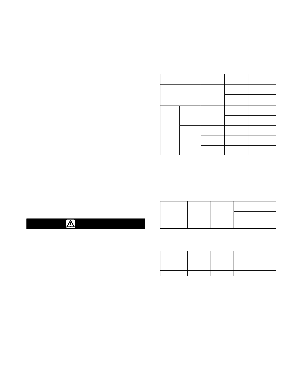
1. The correlation of approved DVC6000f Series
digital valve controllers in specific product type, Ex
marking and operating ambient temperature this
time is as follows:
Mounting Style
Integral Mounting
Main Unit DVC6005f
Separate
Mounting
Feedback
Unit
Product
Type
DVC6010f
DVC6020f
DVC6030f
DVC6015 Ex ia II CT6
DVC6025 Ex ia II CT5
DVC6035 Ex ia II CT4
Ex Marking
Ex ia II CT6
Ex ia II CT5
Ex ia II CT6
Ex ia II CT5
Ambient
Temperature
−40_C to
+75_C
−40_C to
+80_C
−40_C to
+75_C
−40_C to
+80_C
−60_C to
+80_C
−60_C to
+95_C
−60_C to
+125_C
2. The enclosure of the controller provides a
grounding terminal, and the user should install a
reliable grounding wire connected to it when
mounting and using the controller.
3. The values for intrinsically safe parameters and
maximum internal equivalent parameters of the
controller are as follow:
Max Input
Voltage
Ui (V)
24 226 1.4 5 0
17.5 380 5.32 5 0
Max Input
Current
Ii (mA)
Max Input
Power
Pi (W)
Max Internal
Equivalent Parameter
Ci (nF) Li (mH)
Failure to follow these conditions of
safe use could result in personal injury
or property damage from fire or
explosion, or area re-classification.
NEPSI Intrinsic Safety
Notes for Safe Use of the Certified Product
DVC6000f series digital valve controllers
(designated as controller hereafter) have been
proved to be in conformity with the requirements
specified in the national standards GB3836.1-2000
and GB3836.4-2000 through inspections conducted
by National Supervision and Inspection Centre for
Explosion Protection and Safety of Instrumentation
(NEPSI). The Ex marking for the products is Ex ia II
CT6/T5/T4, and their Ex certificate number is
GYJ06280. When using the product, the user should
pay attention to the items stated below:
4. As a main unit of a separate design product, the
values for intrinsically safe output parameters of
DVC6005f are as follows:
Max Output
Voltage
Uo (V)
8.6 2.3 5 8.2 100
Max
Output
Current
Io (mA)
Max
Output
Power
Po (mW)
Max Equivalent
Parameter allowed
Co (mF) Lo (mH)
5. While the controller forms an intrinsically safe
explosion protection system together with an
associated equipment, the following requirements
must be met: Uo vUi, Io vIi, Po vPi, Co wCi + Cc,
Lo wLi + Lc.
Note
Where Cc and Lc represent
distributing capacitance and
inductance of the connecting cable
respectively.
6. The connection cable between the product and
associated equipment should be a cable with
3
Page 4

DVC6000f Series
Errata Sheet
April 2007
insulation screen and sheath. The screen should be
connected to the ground.
7. An appropriate heat-resistant cable should be
selected for use with the controller in an application
where the ambient temperature exceeds 70_C.
8. When using and maintaining the product in the
field, cleaning the plastic surface of the product with
dry cloth is strictly prohibited to avoid the risk of
producing electrical spark.
9. The user must not be allowed to replace at will
the electric components of the product on his own to
avoid damage to the intrinsically safe performance of
explosion protection of the product.
10. The user must follow the relevant rules specified
by the product instruction manual, the “13th Section
of Electric Equipment Used in Explosive Gaseous
Environment: Maintenance of Electric Equipment
Used in Explosive Gaseous Environment” of
GB3836.13-1997 standard, the “15th Section of
Electric Equipment Used in Explosive Gaseous
Environment: Electric Installation in Hazardous
Locations (except for coal mine)” of
GB3836.15-2000 standard and the “Electric
installation construction and acceptance test code
for electric equipment mounting engineering in an
explosive and fire-hazardous environment” of
GB50257:1996 standard while performing
installation, operation, and maintenance for the
product.
NEPSI Flameproof
DVC6000f Series digital valve controllers
(designated as controller hereafter) have been
proved to be in conformity with the requirements
specified in the national standards GB3836.1-2000
and GB3836.2-2000 through inspections conducted
by National Supervision and Inspection Centre for
Explosion Protection and Safety of Instrumentation
(NEPSI). The Ex markings for the products are Ex d
II B+H2T6/T5 (DVC6010f, DVC6020f, and
DVC6030f only), Ex d II BT6/T5 (DVC6005f only),
and Ex d II CT6/T5/T4 (DVC6015, DVC6025, and
DVC6035 only) respectively and their Ex certificate
number is GYJ06279. When using the product , the
user should pay attention to the items stated below:
1. The correlation of this approved DVC6000f
Series digital valve controllers in specific product
type, Ex marking, and operating ambient
temperature is as follows:
Product Type Ex Marking
DVC6010f, DVC6020f,
DVC6030f (integral design)
DVC6005f (main unit of
separate design)
DVC6015, DVC6025,
DVC6035 (feedback units
of separate design
Ex d II B+H2T6
Ex d II B+H2T5
Ex d II BT6
Ex d II BT5
Ex d II CT6
Ex d II CT5
Ex d II CT4
Ambient
Temperature
−40_C to
+75_C
−40_C to
+80_C
−40_C to
+75_C
−40_C to
+80_C
−60_C to
+80_C
−60_C to
+95_C
−60_C to
+125_C
2. The enclosure of the controller provides a
grounding terminal, and the user should install a
reliable grounding wire connected to it when
mounting and using the controller.
3. The controller’s cable entrance (1/2 NPT) must
be fitted with a cable entry device which is
Ex−approved through inspection of explosion
protection, in conformity with relevant standards of
GB3836.1-2000 and GB3836.2-2000 and has a
corresponding rating of explosion protection.
4. An appropriate heat−resistant cable should be
selected for use with the controller in an application
where the ambient temperature exceeds 70_C.
5. The principle of “Opening equipment’s cover is
strictly prohibited while its is active” must be abided
by when using and maintaining the controller in the
field.
6. The user must follow the relevant rules specified
by the product instruction manual, the “13th Section
of Electric Equipment Used in Explosive Gaseous
Environment: Maintenance of Electric Equipment
Used in Explosive Gaseous Environment” of
GB3836.13-1997 standard, the “15th Section of
Electric Equipment Used in Explosive Gaseous
Environment: Electric Installation in Hazardous
Locations (except for coal mine)” of
GB3836.15-2000 standard and the “Electric
installation construction and acceptance test code
for electric equipment mounting engineering in an
explosive and fire-hazardous environment” of
GB50257:1996 standard while performing
installation, operation, and maintenance for the
product.
4
Page 5

Errata Sheet
April 2007
DVC6000f Series
TYPE DVC6010f, DVC6020f, DVC6030f
TYPE DVC6005f
TYPE DVC6015, DVC6025, DVC6035
Figure 1. NEPSI Intrinsic Safety and Flameproof Nameplates
5
Page 6

DVC6000f Series
Errata Sheet
April 2007
FIELDVUE and Fisher are marks owned by Fisher Controls International LLC, a member of the Emerson Process Management business division of
Emerson Electric Co. Emerson and the Emerson logo are trademarks and service marks of Emerson Electric Co. All other marks are the property
of their respective owners.
The contents of this publication are presented for informational purposes only, and while every effort has been made to ensure their accuracy, they are
not to be construed as warranties or guarantees, express or implied, regarding the products or services described herein or their use or applicability.
We reserve the right to modify or improve the designs or specifications of such products at any time without notice.
Neither Emerson, Emerson Process Management, nor any of their affiliated entities assumes responsibility for the selection, use and
maintenance of any product. Responsibility for the selection, use and maintenance of any product remains with the purchaser and end-user.
Emerson Process Management
Marshalltown, Iowa 50158 USA
Cernay 68700 France
Sao Paulo 05424 Brazil
Singapore 128461
www.Fisher.com
6
EFisher Controls International LLC 2006, 2007; All Rights Reserved Printed in USA
Page 7

DVC6000f Series
FIELDVUE DVC6000f Series
Digital Valve Controllers
Instruction Manual
Form 5774
March 6, 2006
This manual applies to:
Standard Control (SC)
Fieldbus Control (FC)
Fieldbus Logic (FL)
Introduction
Installation
375 Field Communicator Basics
Basic Setup and Tuning
Detailed Setup / Blocks
Calibration
Viewing Device Information
Principle of Operation
PlantWeb
Maintenance
Alerts
1
2
3
4
5
6
7
8
9
10
Parts
OUNDATION Fieldbus Communication
F
Device Description (DD) Installation
Operating with DeltaV
Loop Schematics/Nameplates
Glossary
Index
Index
11
A
B
C
D
Glossary
16
Index
D103189X012
www.Fisher.com
Page 8

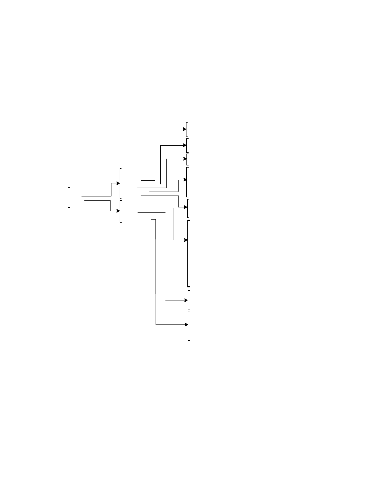
Model 375 Field Communicator Menu Tree for
FIELDVUE
Initial Setup
Basic Setup
Setup Wizard
Auto Tvl Calib
Stabilize/Optimize
Detailed Setup
Trans Block Mode
Protection
Initial Setup
Response Control
Alerts
Instrument
Act and Valve
2
Other
Display
Trans Block Mode
:Setpoint
:Travel
Drive Signal
:Supply Press
:Pressure A
:Pressure B
:Pressure Diff
Temperature
:Tvl/Press State
Input Char
Online
Basic Setup
Detailed Setup
Display
Calibrate
Instrument Status
Stroke Valve
Calibrate
Auto Tvl Calib
Manual Tvl Calib
Relay Adjust
Travel Sensor Adjust
Supply Press Sensor Cal
Output A Sensor Cal
Output B Sensor Cal
Instrument Status
Instrument Alerts
PlantWeb Alerts
This menu is only available in DD Revisions 3 and 4.
1
2
This menu item will read Simulate PlantWeb Alarms in DD Revisions 2
and 3, and Other in DD Revision 4. See the Simulate PlantWeb Alarms
menu for DD Revision 2 and 3.
3
This menu item only available in DD Revision 4
Cycle Count
Travel Accum
Tvl Count
Tvl Press Status
Device Record
Other
Simulate PlantWeb Alarms
Block Error Reporting
Simulate PlantWeb Alarms
PWA Simulate
Simulate Active Alarms
Tvl Press Status
:Travel
:Travel Status
:Supply Press
:Supply Press Status
:Pressure A
:Pressure A Status
:Pressure B
:Pressure B Status
:Pressure Diff
:Pressure Diff Status
Device Record
:Temp Max
:Temp Max Time
:Temp Min
:Temp Min Time
:Supp Press Max
:Supp Press Max Time
:Supp Press Min
:Supp Press Min Time
Response Control
Alerts
Instrument
Act and Valve
Simulate Active Alarms
Failed Active
Maint Active
Advise Active
Menu Tree for Model 375 Field Communicator
R
DVC6000f Digital Valve Controllers
Transducer Block
Travel Tuning
:Tvl/Press Select
:Zero Pwr Cond
Tvl Cutoff Low
:Actuator Style
:Relay Type
:Feedback Conn
:Tvl Sen Motion
:Tvl Cal Trigger
Travel Tuning
Pressure Tuning
Tvl Press Control
Input Char
Define Custom Char
PW Alarm Enable
PW Alarm Reporting
Elect and Config
Sensor and Enviro
Tvl and Prox
Performance
:Max Supp Press
Pressure Units
Temperature Units
Tvl Units
Length Units
Area Units
Spring Rate Units
Tag Description
:Relay Type
Calib Person
Calib Location
Calib Date
MAI Channel Map
Valve
Trim
Actuator
Reference
3
:Tvl Tuning Set
Tvl Prop Gain
Tvl Velocity Gain
:Tvl MLFB Gain
:Tvl Integ Enable
Tvl Integral Gain
:Tvl Integ DeadZ
:Tvl Integ Lim Hi
:Tvl Integ Lim Lo
Tvl Press Control
:Tvl/Press Select
Tvl Cutoff Hi
Tvl Cutoff Lo
1
:Press Cutoff Hi
:Press Cutoff Lo
:Press Range Hi
:Press Range Lo
MAI Channel Map
MAI Channel 1
MAI Channel 2
MAI Channel 3
MAI Channel 4
MAI Channel 5
MAI Channel 6
MAI Channel 7
MAI Channel 8
Valve
Valve Manufacturer Id
Valve Model Number
Valve Serial Number
Valve Style
:Valve Size
:Valve Class
:Rated Travel
:Actual Travel
:Shaft Stem Dia
:Packing Type
:Inlet Pressure
:Outlet Pressure
Trim
:Seat Type
:Leak Class
:Port Diameter
:Port Type
:Flow Direction
:Push Down To
:Flow Tends To
:Unbalanced Area
Actuator
Actuator Manufacturer Id
Actuator Model Number
Actuator Serial Number
:Actuator Size
Actuator Fail Action
:Feedback Conn
:Tvl Sen Motion
:Effective Area
:Air
:Lower Bench Set
:Upper Bench Set
:Nominal Supply Pressure
:Spring Rate
:Lever Style
:Moment Arm
Reference
:Trim Style 1
:Trim Style 2
:Stroking Time Open
:Stroking Time Close
DVC6000f DD Revision 2, 3, and 4
Pressure Tuning
:Press Tuning Set
:Press Prop Gain
:Press MLFB Gain
:Press Integ Gain
:Press Integ DeadZ
:Press Integ Hi Lim
:Press Integ Lo Lim
PW Alarm Enable
Failed Enable
Maint Enable
Advise Enable
PW Alarm Reporting
Failed Suppress
Maint Suppress
Advise Supress
Elect and Config
:Elect Active
:Elect Enable
:Shutdown Trigger
:Shutdown Recovery
Drive Current Config
Drive Signal
:Output Blk Timeout
Alert Key
Sensor and Enviro
:Sensor Active
:Sensor Enable
:Shutdown Trigger
:Shutdown Recovery
:Enviro Active
:Enviro Enable
Supply Press Sensor Config
Temp Sensor Config
Tvl and Prox
:Tvl Active
:Travel Enable
Tvl Config
:Prox Active
:Prox Enable
Prox Config
:Tvl History Active
:Tvl History Enable
Tvl History Config
Performance
:Performance Active
:Performance Enable
1
:PD Run
:PD Inside Status
1
Drive Current Config
Drive Current
:Drive Current Alrt Pt
:Drive Current Alrt Time
Supply Press Sensor Config
:Supply Press
:Supply Press Hi Alrt Pt
:Supply Press Lo Alrt Pt
Temp Sensor Config
Temperature
:Temp Hi Alrt Pt
:Temp Lo Alrt Pt
Tvl Config
:Travel
Tvl Deviation
:Tvl Dev Alrt Pt
:Tvl Dev Time
:Tvl Dev DB
:Tvl Lo Lo Alrt Pt
:Tvl Lo Lo DB
:Tvl Lo Alrt Pt
:Tvl Lo DB
:Tvl Hi Alrt Pt
:Tvl Hi DB
:Tvl Hi Hi Alrt Pt
:Tvl Hi Hi DB
Prox Config
:Tvl Open Alrt Pt
:Tvl Open DB
:Tvl Closed Alrt Pt
:Tvl Closed DB
Tvl History Config
Cycle Count
:Cycle Count Alrt Pt
:Cycle Count DB
Travel Accum
:Tvl Accum Alrt Pt
:Tvl Accum DB
i
i
Page 9

375 Field Communicator Transducer Block Menu Structure
PARAMETER LABEL PARAMETER NAME MENU STRUCTURE
Actual Travel ACTUAL_TRAVEL TB > Detailed Setup > Act and Valve > Valve > Actual Travel
Actuator Fail Action ACT_FAIL_ACTION TB > Detailed Setup > Act and Valve > Actuator > Actuator Fail Action
Actuator Manufacturer Id ACT_MAN_ID TB > Detailed Setup > Act and Valve > Actuator >Actuator Manufacturer Id
Actuator Model Number ACT_MODEL_NUM TB > Detailed Setup > Act and Valve > Actuator > Actuator Model Number
Actuator Serial Number ACT_SN TB > Detailed Setup > Act and Valve > Actuator > Actuator Serial Number
Actuator Size ACTUATOR_SIZE TB > Detailed Setup > Act and Valve > Actuator > Actuator Size
Actuator Style ACTUATOR_STYLE TB > Detailed Setup > Initial Setup > Actuator Style
Advise Active ADVISE_ACTIVE TB > Instrument Status > PlantWeb Alerts > Advise Active
Advise Enable ADVISE_ENABLE TB > Detailed Setup > Alerts > PW Alarm Enable > Advise Enable
Advise Suppress ADVISE_MASK TB > Detailed Setup > Alerts > PW Alarm Reporting > Advise Suppress
Air AIR TB > Detailed Setup > Act and Valve > Actuator > Air
Alert Key ALERT_KEY TB > Detailed Setup > Alerts > Elect and Config > Alert Key
Area Units AREA_UNITS TB > Detailed Setup > Instrument > Area Units
Calib Date XD_CAL_DATE TB > Detailed Setup > Instrument > Calib Date
Calib Location XD_CAL_LOC TB > Detailed Setup > Instrument > Calib Location
Calib Person XD_CAL_WHO TB > Detailed Setup > Instrument > Calib Person
Cycle Count CYCLE_COUNT TB > Detailed Setup > Alerts > Tvl and Prox > Tvl History Config > Cycle Count
Cycle Count Alrt Pt CYCLE_COUNT_ALRT_PT TB > Detailed Setup > Alerts > Tvl and Prox > Tvl History Config > Cycle Count Alrt Pt
Cycle Count DB CYCLE_COUNT_DB TB > Detailed Setup > Alerts > Tvl and Prox > Tvl History Config > Cycle Count DB
Drive Current DRIVE_CURRENT TB > Detailed Setup > Alerts > Elect and Config > Drive Current
Drive Current Alrt Pt DRIVE_CURRENT_ALRT_PT TB > Detailed Setup > Alerts > Elect and Config > Drive Current Alrt Pt
Drive Current Alrt Time DRIVE_CURRENT_TIME TB > Detailed Setup > Alerts > Elect and Config > Drive Current Alrt Time
Drive Signal DRIVE_SIGNAL TB > Detailed Setup > Alerts > Elect and Config > Drive Signal
Effective Area EFFECTIVE_AREA TB > Detailed Setup > Act and Valve > Actuator > Effective Area
Elect Active ELECT_ACTIVE TB > Detailed Setup > Alerts > Elect and Config > Elect Active or TB > Instrument Status > Instrument Alerts
Elect Enable ELECT_ENABLE TB > Detailed Setup > Alerts > Elect and Config > Elect Enable
Enviro Active ENVIRO_ACTIVE TB > Detailed Setup > Alerts > Sensor and Enviro > Enviro Active or TB > Instrument Status > Instrument Alerts
Enviro Enable ENVIRO_ENABLE TB > Detailed Setup > Alerts > Sensor and Enviro > Enviro Enable
Failed Active FAILED_ACTIVE TB > Instrument Status > PlantWeb Alerts > Failed Active
Failed Enable FAILED_ENABLE TB > Detailed Setup > Alerts > PW Alarm Enable > Failed Enable
Failed Suppress FAILED_MASK TB > Detailed Setup > Alerts > PW Alarm Reporting > Failed Suppress
Feedback Conn FEEDBACK_CONN TB > Detailed Setup > Act and Valve > Actuator > Feedback Conn
Flow Direction FLOW_DIRECTION TB > Detailed Setup > Act and Valve > Trim > Flow Direction
Flow Tends To FLOW_TENDS_TO TB > Detailed Setup > Act and Valve > Trim > Flow Tends To
Inlet Pressure INLET_PRESSURE TB > Detailed Setup > Act and Valve > Valve > Inlet Pressure
Input Char INPUT_CHAR TB > Detailed Setup > Response Control > Input Char
Leak Class LEAK_CLASS TB > Detailed Setup > Act and Valve > Trim > Leak Class
Length Units LENGTH_UNITS TB > Detailed Setup > Instrument > Length Units
Lever Style LEVER_STYLE TB > Detailed Setup > Act and Valve > Actuator > Lever Style
Lower Bench Set LOWER_BENCH_SET TB > Detailed Setup > Act and Valve > Actuator > Lower Bench Set
MAI Channel 1 MAI_CHANNEL_1 TB > Detailed Setup > Instrument > MAI Channel Map > MAI Channel 1
MAI Channel 2 MAI_CHANNEL_2 TB > Detailed Setup > Instrument > MAI Channel Map > MAI Channel 2
MAI Channel 3 MAI_CHANNEL_3 TB > Detailed Setup > Instrument > MAI Channel Map > MAI Channel 3
MAI Channel 4 MAI_CHANNEL_4 TB > Detailed Setup > Instrument > MAI Channel Map > MAI Channel 4
MAI Channel 5 MAI_CHANNEL_5 TB > Detailed Setup > Instrument > MAI Channel Map > MAI Channel 5
MAI Channel 6 MAI_CHANNEL_6 TB > Detailed Setup > Instrument > MAI Channel Map > MAI Channel 6
MAI Channel 7 MAI_CHANNEL_7 TB > Detailed Setup > Instrument > MAI Channel Map > MAI Channel 7
MAI Channel 8 MAI_CHANNEL_8 TB > Detailed Setup > Instrument > MAI Channel Map > MAI Channel 8
Maint Active MAINT_ACTIVE TB > Instrument Status > PlantWeb Alerts > Maint Active
Maint Enable MAINT_ENABLE TB > Detailed Setup > Alerts > PW Alarm Enable > Maint Enable
Maint Suppress MAINT_MASK TB > Detailed Setup > Alerts > PW Alarm Reporting > Maint Suppress
Max Supp Press MAX_SUPP_PRESS TB > Detailed Setup > Instrument > Max Supp Press
Moment Arm MOMENT_ARM TB > Detailed Setup > Act and Valve > Actuator > Moment Arm
Nominal Supply Pressure NOMINAL_SUPPLY_PRESSURE TB > Detailed Setup > Act and Valve > Actuator > Nominal Supply Pressure
Outlet Pressure OUTLET_PRESSURE TB > Detailed Setup > Act and Valve > Valve > Outlet Pressure
Output Blk Timeout OUTPUT_BLK_TIMEOUT TB > Detailed Setup > Alerts > Elect and Config > Output Blk Timeout
−Continued−
ii
ii
Page 10

375 Field Communicator Transducer Block Menu Structure (Continued)
PARAMETER LABEL MENU STRUCTUREPARAMETER NAME
Packing Type PACKING_TYPE TB > Detailed Setup > Act and Valve > Valve > Packing Type
PD Inside Status PD_STATUS TB > Detailed Setup > Alerts > Performance > PD Status
PD Run PD_RUN TB > Detailed Setup > Alerts > Performance > PD Run
Performance Active PERF_ACTIVE TB > Detailed Setup > Alerts > Performance > Performance Active or TB > Instrument Status > Instrument Alerts
Performance Enable PERF_ENABLE TB > Detailed Setup > Alerts > Performance Enable
Port Diameter PORT_DIAMETER TB > Detailed Setup > Act and Valve > Trim > Port Diameter
Port Type PORT_TYPE TB > Detailed Setup > Act and Valve > Trim > Port Type
Press Cutoff Hi PRESS_CUTOFF_HI TB > Detailed Setup > Response Control > Tvl/Press Control > Press Cutoff Hi
Press Cutoff Lo PRESS_CUTOFF_LO TB > Detailed Setup > Response Control > Tvl/Press Control > Press Cutoff Lo
Press Integ DeadZ PRESS_INTEG_DEADZ TB > Detailed Setup > Response Control > Pressure Tuning > Press Integ DeadZ
Press Integ Gain PRESS_INTEG_GAIN TB > Detailed Setup > Response Control > Pressure Tuning > Press Integ Gain
Press MLFB Gain PRESS_MLFB_GAIN TB > Detailed Setup > Response Control > Pressure Tuning > Press MLFB Gain
Press Prop Gain PRESS_PROP_GAIN TB > Detailed Setup > Response Control > Pressure Tuning > Press Prop Gain
Press Range Hi PRESS_RANGE_HI TB > Detailed Setup > Response Control > Tvl/Press Control > Press Range Hi
Press Range Lo PRESS_RANGE_LO TB > Detailed Setup > Response Control > Tvl/Press Control > Press Range Lo
Press Tuning Set PRESS_TUNING_SET TB > Detailed Setup > Response Control > Pressure Tuning > Press Tuning Set
Pressure A PRESSURE_A.VALUE TB > Display > Tvl Press Status > Pressure A
Pressure A Status PRESSURE_A.STATUS TB > Display > Tvl Press Status > Pressure A Status
Pressure B PRESSURE_B.VALUE TB > Display > Tvl Press Status > Pressure B
Pressure B Status PRESSURE_B.STATUS TB > Display > Tvl Press Status > Pressure B Status
Pressure Diff PRESSURE_DIFF.VALUE TB > Display > Pressure Diff
Pressure Diff Status PRESSURE_DIFF.STATUS TB > Display > Tvl Press Status > Pressure Diff Status
Pressure Units PRESSURE_UNITS TB > Detailed Setup > Instrument > Pressure Units
Prox Active PROX_ACTIVE TB > Detailed Setup > Alerts > Tvl and Prox > Prox Active or TB > Instrument Status > Instrument Alerts
Prox Enable PROX_ENABLE TB > Detailed Setup > Alerts > Tvl and Prox > Prox Enable
Push Down To PUSH_DOWN_TO TB > Detailed Setup > Act and Valve > Trim > Push Down To
PWA Simulate PWA_SIMULATE TB > Detailed Setup > Simulate PlantWeb Alarms > PWA Simulate
Rated Travel RATED_TRAVEL TB > Detailed Setup > Act and Valve > Valve > Rated Travel
Relay Type RELAY_TYPE TB > Detailed Setup > Initial Setup > Relay Type
Seat Type SEAT_TYPE TB > Detailed Setup > Act and Valve > Trim > Seat Type
Setpoint FINAL_VALUE.VALUE TB > Display > Setpoint
Sensor Active SENSOR_ACTIVE
Sensor Enable SENSOR_ENABLE TB > Detailed Setup > Alerts > Sensor and Enviro > Sensor Enable
Shaft Stem Dia SHAFT_STEM_DIA TB > Detailed Setup > Act and Valve > Valve > Shaft Stem Dia
Shutdown Recovery SHUTDOWN_RECOVERY TB > Detailed Setup > Alerts > Elect and Config > Shutdown Recovery
Shutdown Trigger SHUTDOWN_TRIGGER TB > Detailed Setup > Alerts > Elect and Config > Shutdown Trigger
Spring Rate SPRING_RATE TB > Detailed Setup > Act and Valve > Actuator > Spring Rate
Spring Rate Units SPRING_RATE_UNITS TB > Detailed Setup > Instrument > Spring Rate Units
Stroking Time Close STROKING_TIME_CLOSE TB > Detailed Setup > Act and Valve > Reference > Stroking Time Close
Stroking Time Open STROKING_TIME_OPEN TB > Detailed Setup > Act and Valve > Reference > Stroking Time Open
Supply Press SUPPLY_PRESS.VALUE TB > Detailed Setup > Alerts > Sensor and Enviro > Supply Press Sensor Config > Supply Press
Supply Press Hi Alrt Pt SUP_PRES_HI_ALRT_PT TB > Detailed Setup > Alerts > Sensor and Enviro > Supply Press Sensor Config > Supply Press Hi Alrt Pt
Supply Press Lo Alrt Pt SUP_PRES_LO_ALRT_PT TB > Detailed Setup > Alerts > Sensor and Enviro > Supply Press Sensor Config > Supply Press Lo Alrt Pt
Supp Press Max SUPP_PRESS_MAX TB > Display > Device Record > Supp Press Max
Supp Press Max Time SUPP_PRESS_MAX_TIME TB > Display > Device Record > Supp Press Max Time
Supp Press Min SUPP_PRESS_MIN TB > Display > Device Record > Supp Press Min
Supp Press Min Time SUPP_PRESS_MIN_TIME TB > Display > Device Record > Supp Press Min Time
Supply Press Status SUPPLY_PRESSURE.STATUS TB > Display > Tvl Press Status > Supply Press Status
Tag Description TAG_DESC TB > Detailed Setup > Instrument > Tag Description
Temperature TEMPERATURE TB > Detailed Setup > Alerts > Sensor and Enviro > Temp Sensor Config > Temperature
Temp Hi Alrt Pt TEMP_HI_ALRT_PT TB > Detailed Setup > Alerts > Sensor and Enviro > Temp Sensor Config > Temp Hi Alrt Pt
Temp Lo Alrt Pt TEMP_LO_ALRT_PT TB > Detailed Setup > Alerts > Sensor and Enviro > Temp Sensor Config > Temp Lo Alrt Pt
Temp Max TEMP_MAX TB > Display > Device Record > Temp Max
Temp Max Time TEMP_MAX_TIME TB > Display > Device Record > Temp Max Time
Temp Min TEMP_MIN TB > Display > Device Record > Temp Min
TB > Detailed Setup > Alerts > Sensor and Enviro > Sensor Active or
TB > Instrument Status > Instrument Alerts
−Continued−
iii
iii
Page 11

375 Field Communicator Transducer Block Menu Structure (Continued)
PARAMETER LABEL MENU STRUCTUREPARAMETER NAME
Temp Min Time TEMP_MIN_TIME TB > Display > Device Record > Temp Min Time
Temperature Units TEMPERATURE_UNITS TB > Detailed Setup > Instrument > Temperature Units
Travel TRAVEL.VALUE TB > Detailed Setup > Alerts > Tvl and Prox > Travel Config > Travel
Travel Accum TRAVEL_ACCUM TB > Detailed Setup > Alerts > Tvl and Prox > Tvl History Config > Travel Accum
Travel Enable TRAVEL_ENABLE TB > Detailed Setup > Alerts > Tvl and Prox > Travel Enable
Travel Status TRAVEL.STATUS TB > Display > Tvl Press Status > Travel Status
Trim Style 2 TRIM_STYLE_2 TB > Detailed Setup > Act and Valve > Reference > Trim Style 2
Trim Style 1 TRIM_STYLE_1 TB > Detailed Setup > Act and Valve > Reference > Trim Style 1
Tvl Accum Alrt Pt TVL_ACCUM_ALRT_PT TB > Detailed Setup > Alerts > Tvl and Prox > Tvl History Config > Tvl Accum Alrt Pt
Tvl Accum DB TVL_ACCUM_DB TB > Detailed Setup > Alerts > Tvl and Prox > Tvl History Config > Tvl Accum DB
Tvl Active TRAVEL_ACTIVE TB > Detailed Setup > Alerts > Tvl and Prox > Tvl Active or TB > Instrument Status > Instrument Alerts
Tvl Cal Trigger TVL_CAL_TRIGGER TB > Detailed Setup > Initial Setup > Tvl Cal Trigger
Tvl Closed Alrt Pt TVL_CLOSED_ALRT_PT TB > Detailed Setup > Alerts > Tvl and Prox > Prox Config > Tvl Closed Alrt Pt
Tvl Closed DB TVL_CLOSED_DB TB > Detailed Setup > Alerts > Tvl and Prox > Prox Config > Tvl Closed DB
Tvl Count TVL_COUNT TB > Display >Tvl Count
Tvl Cutoff Hi FINAL_VALUE_CUTOFF_HI TB > Detailed Setup > Response Control > Tvl/Press Control > Tvl Cutoff Hi
Tvl Cutoff Lo FINAL_VALUE_CUTOFF_LO TB > Detailed Setup > Response Control > Tvl/Press Control > Tvl Cutoff Lo
Tvl Dev Alrt Pt TVL_DEV_ALRT_PT TB > Detailed Setup > Alerts > Tvl and Prox > Travel Config > Tvl Dev Alrt Pt
Tvl Deviation TRAVEL_DEVIATION TB > Detailed Setup > Alerts > Tvl and Prox > Travel Config > Tvl Deviation
Tvl Dev Time TVL_DEV_TIME TB > Detailed Setup > Alerts > Tvl and Prox > Travel Config > Tvl Dev Time
Tvl Dev DB TVL_DEV_DB TB > Detailed Setup > Alerts > Tvl and Prox > Travel Config > Tvl Dev DB
Tvl Hi Alrt Pt TVL_HI_ALRT_PT TB > Detailed Setup > Alerts > Tvl and Prox > Travel Config > Tvl Hi Alrt Pt
Tvl Hi DB TVL_HI_DB TB > Detailed Setup > Alerts > Tvl and Prox > Travel Config > Tvl Hi DB
Tvl Hi Hi Alrt Pt TVL_HI_HI_ALRT_PT TB > Detailed Setup > Alerts > Tvl and Prox > Travel Config > Tvl Hi Hi Alrt Pt
Tvl Hi Hi DB TVL_HI_HI_DB TB > Detailed Setup > Alerts > Tvl and Prox > Travel Config > Tvl Hi Hi DB
Tvl History Active TVL_HISTORY_ACTIVE TB > Detailed Setup > Alerts > Tvl and Prox > Tvl History Active or TB > Instrument Status > Instrument Alerts
Tvl History Enable TVL_HISTORY_ENABLE TB > Detailed Setup > Alerts > Tvl and Prox > Tvl History Enable
Tvl Integ DeadZ TVL_INTEG_DEADZ TB > Detailed Setup > Response Control > Travel Tuning > Tvl Integ DeadZ
Tvl Integ Enable TVL_INTEG_ENABLE TB > Detailed Setup > Response Control > Travel Tuning > Tvl Integ Enable
Tvl Integ Lim Hi TVL_INTEG_LIM_HI TB > Detailed Setup > Response Control > Travel Tuning > Tvl Integ Lim Hi
Tvl Integ Lim Lo TVL_INTEG_LIM_LO TB > Detailed Setup > Response Control > Travel Tuning > Tvl Integ Lim Lo
Tvl Integral Gain SERVO_RESET TB > Detailed Setup > Response Control > Travel Tuning > Tvl Integral Gain
Tvl Lo Alrt Pt TVL_LO_ALRT_PT TB > Detailed Setup > Alerts > Tvl and Prox > Travel Config > Tvl Lo Alrt Pt
Tvl Lo DB TVL_LO_DB TB > Detailed Setup > Alerts > Tvl and Prox > Travel Config > Tvl Lo DB
Tvl Lo Lo Alrt Pt TVL_LO_LO_ALRT_PT TB > Detailed Setup > Alerts > Tvl and Prox > Travel Config > Tvl Lo Lo Alrt Pt
Tvl Lo Lo DB TVL_LO_LO_DB TB > Detailed Setup > Alerts > Tvl and Prox > Travel Config > Tvl Lo Lo DB
Tvl MLFB Gain TVL_MLFB_GAIN TB > Detailed Setup > Response Control > Travel Tuning > Tvl MLFB Gain
Tvl Open Alrt Pt TVL_OPEN_ALRT_PT TB > Detailed Setup > Alerts > Tvl and Prox > Prox Config > Tvl Open Alrt Pt
Tvl Open DB TVL_OPEN_DB TB > Detailed Setup > Alerts > Tvl and Prox > Prox Config > Tvl Open DB
Tvl/Press Select TVL_PRESS_SELECT TB > Detailed Setup > Response Control > Tvl/Press Control > Tvl/Press Select
Tvl/Press State TVL_PRESS_STATE TB > Display > Tvl/Press State
Tvl Prop Gain SERVO_GAIN TB > Detailed Setup > Response Control > Travel Tuning > Tvl Prop Gain
Tvl Sen Motion TRAVEL_SENSOR_MOTION TB > Detailed Setup > Act and Valve > Actuator > Tvl Sen Motion
Tvl Sen Motion TRAVEL_SENSOR_MOTION TB > Detailed Setup > Initial Setup > Tvl Sen Motion
Tvl Tuning Set TVL_TUNING_SET TB > Detailed Setup > Response Control > Travel Tuning > Tvl Tuning Set
Tvl Units TVL_UNITS TB > Detailed Setup > Instrument > Tvl Units
Tvl Velocity Gain SERVO_RATE TB > Detailed Setup > Response Control > Travel Tuning > Tvl Velocity Gain
Unbalanced Area UNBALANCED_AREA TB > Detailed Setup > Act and Valve > Trim > Unbalanced Area
Upper Bench Set UPPER_BENCH_SET TB > Detailed Setup > Act and Valve > Actuator > Upper Bench Set
Valve Class VALVE_CLASS TB > Detailed Setup > Act and Valve > Valve > Class
Valve Manufacturer Id VALVE_MAN_ID TB > Detailed Setup > Act and Valve > Valve > Valve Manufacturer Id
Valve Model Number VALVE_MODEL_NUM TB > Detailed Setup > Act and Valve > Valve > Valve Model Number
Valve Serial Number VALVE_SN TB > Detailed Setup > Act and Valve > Valve > Valve Serial Number
Valve Size VALVE_SIZE TB > Detailed Setup > Act and Valve > Valve > Valve Size
Valve Style VALVE_TYPE TB > Detailed Setup > Act and Valve > Valve > Valve Style
Zero Pwr Cond ZERO_PWR_COND TB > Detailed Setup > Initial Setup > Zero Pwr Cond
iv
iv
Page 12
Online
Setup
Display
Restart
Model 375 Field Communicator Menu Tree for
R
FIELDVUE
DVC6000f Digital Valve Controllers
Resource Block
WriteLock
Write Lock
Write Priority
Comm Time Out
RCas Timeout
ROut Timeout
Options
Feature Selection
Setup
Res Block Mode
WriteLock
Comm Time Out
Options
Alarm Handling
Instrument
Display
Instrument
Options
DD Information
Resource Status
Alarm Handling
Alert Key
Confirm Time
Max Alerts Allow
Acknowledge Option
Alarm Summary: Disabled
Block Alarm: Unacknowledged
Instrument
Strategy
Tag Description
Field Serial Number
Instrument
Strategy
Tag Description
Device ID
Electronics Serial Number
Factory Serial Number
Field Serial Number
Manufacturer ID
Device Type
Device Revision
DD Revision
ITK Version
Features
:Software Rev All
:Stby Software Rev All
Hardware Revision
Options
Diag Options
Function Block Options
Misc Options
Resource Status
Block Error
Block Alarm: Unacknowledged
Device State
Fault State
Write Lock
Write Alarm: Alarm State
Menu Tree for Model 375 Field Communicator
DVC6000f DD Revision 2, 3, and 4
v
v
Page 13

375 Field Communicator Resource Block Menu Structure
PARAMETER LABEL PARAMETER NAME MENU STRUCTURE
Acknowledge Option ACK_OPTION RB > Setup > Alarm Handling > Acknowledge Option
Alarm Summary: Disabled ALARM_SUM.DISABLED RB > Setup > Alarm Handling > Alarm Summary Disabled
Alert Key ALERT_KEY RB > Setup > Alarm Handling > Alert Key
Block Alarm:
Unacknowledged
BLOCK_ALM.UNACKNOWLEDGED
Block Error BLOCK_ERR RB > Display > Resource Status > Block Error
Confirm Time CONFIRM_TIME RB > Setup > Alarm Handling > Confirm Time
Device ID DEVICE_ID RB > Display > Instrument > Device ID
Device Revision DEV_REV RB > Display > Instrument > Device Revision
Device State RS_STATE RB > Display > Resource Status > Device State
Device Type DEV_TYPE RB > Display > Instrument > Device Type
DD Revision DD_REV RB > Display > Instrument > DD Revision
Diag Options DIAG_OPTIONS RB > Display > Options > Diag Options
Electronics Serial Number ELECTRONICS_SN RB > Display > Instrument > Electronics Serial Number
Factory Serial Number FACTORY_SN RB > Display > Instrument > Factory Serial Number
Fault State FAULT_STATE RB > Display > Resource Status > Fault State
Features FEATURES RB > Display > Instrument > Features
Feature Selection FEATURE_SEL RB > Setup > Options > Feature Selection
Field Serial Number FIELD_SN RB > Setup > Instrument > Field Serial Number
Function Block Options FB_OPTIONS RB > Display > Options > Function Block Options
Hardware Revision HARDWARE_REV RB > Display > Instrument > Hardware Revision
ITK Version ITK_VER RB > Display > Instrument > ITK Version
Manufacturer ID MANUFAC_ID RB > Display > Instrument > Manufacturer ID
Max Alerts Allow LIM_NOTIFY RB > Setup > Alarm Handling > Max Alerts Allow
Misc Options MISC_OPTIONS RB > Display > Options > Misc Options
RCas Timeout SHED_RCAS RB > Setup> Comm Time Out > RCas Timeout
ROut Timeout SHED_ROUT RB > Setup > Comm Time Out > ROut Timeout
Software Rev All SOFTWARE_REVISION.SOFTWARE_REV_ALL RB > Display > Instrument > Software Rev All
Stby Software Rev All STBY_SOFTWARE_REV.STBY_SOFTWARE_REV_ALL RB > Display > Instrument > Stby Software Rev All
Strategy STRATEGY RB > Setup > Instrument > Strategy
Tag Description TAG_DESC RB > Setup > Instrument > Tag Description
Write Alarm: Alarm State WRITE_ALM.ALARM_STATE RB > Display > Resource Status > Write Alarm: Alarm State
Write Lock WRITE_LOCK RB > Setup > WriteLock> Write Lock
Write Priority WRITE_PRI RB > Setup > WriteLock> Write Priority
RB > Setup > Alarm Handling > Block Alarm:
Unacknowledged
vi
vi
Page 14
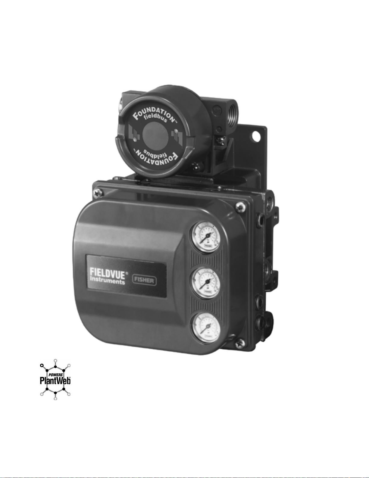
THE FIELDVUE
PLANTWEBt DIGITAL PLANT ARCHITECTURE. THE DIGITAL VALVE CONTROLLER POWERS PLANTWEB
BY CAPTURING AND DELIVERING VALVE DIAGNOSTIC DATA. COUPLED WITH AMS VALVELINK
SOFTWARE, THE DVC6000f PROVIDES USERS WITH AN ACCURATE PICTURE OF VALVE
PERFORMANCE, INCLUDING ACTUAL STEM POSITION, INSTRUMENT INPUT SIGNAL AND PNEUMATIC
PRESSURE TO THE ACTUATOR. USING THIS INFORMATION, THE DIGITAL VALVE CONTROLLER
DIAGNOSES NOT ONLY ITSELF, BUT ALSO THE VALVE AND ACTUATOR TO WHICH IT IS MOUNTED.
R
DVC6000f SERIES DIGITAL VALVE CONTROLLER IS A CORE COMPONENT OF THE
R
FIELDVUEr DVC6000f Series Digital Valve Controller
vii
vii
Page 15

1-1
Introduction
Section 1 Introduction
Scope of Manual 1-2. . . . . . . . . . . . . . . . . . . . . . . . . . . . . . . . . . . . . . . . . . . . . . . . . . . . . . . .
Instrument Description 1-2. . . . . . . . . . . . . . . . . . . . . . . . . . . . . . . . . . . . . . . . . . . . . . . . .
Using this Manual 1-4. . . . . . . . . . . . . . . . . . . . . . . . . . . . . . . . . . . . . . . . . . . . . . . . . . . . . . .
Specifications 1-4. . . . . . . . . . . . . . . . . . . . . . . . . . . . . . . . . . . . . . . . . . . . . . . . . . . . . . . . . . .
Related Information 1-4. . . . . . . . . . . . . . . . . . . . . . . . . . . . . . . . . . . . . . . . . . . . . . . . . . . . .
Fieldbus Installation and Wiring Guidelines 1-4. . . . . . . . . . . . . . . . . . . . . . . . . . . . . . .
Related Documents 1-4. . . . . . . . . . . . . . . . . . . . . . . . . . . . . . . . . . . . . . . . . . . . . . . . . . . . . .
Educational Services 1-4. . . . . . . . . . . . . . . . . . . . . . . . . . . . . . . . . . . . . . . . . . . . . . . . . . .
1
March 2006
1-1
Page 16
DVC6000f Series
Scope of Manual
This instruction manual includes specifications,
installation, operating, and maintenance information
for the DVC6000f Series digital valve controllers. The
manual describes the functionality of the following
FIELDVUE
1
Revision
(Firmware)
1.3, 1.4 4601 1
1. Device descriptions can be downloaded from the internet at www.fieldvue.com.
This manual describes device setup using the Model
375 Field Communicator. For information on using
AMS ValveLink
the appropriate user guide or help.
No person may install, operate, or maintain a
DVC6000f Series digital valve controller without first
being fully trained and qualified in valve, actuator, and
accessory installation, operation and maintenance,
and carefully reading and understanding the
contents of this manual. If you have any questions
concerning these instructions, contact your Emerson
Process Managment
proceeding.
fieldbus instruments:
Device
Type
Device
Revision
DD Compatibility
2.0 or later;
4.0 or later recommended
Software with the instrument, refer to
sales office before
Note
Neither EmersonR, Emerson Process
Management, Fisher
affiliated entities assumes
responsibility for the selection, use or
maintenance of any product.
Responsibility for the selection, use,
or maintenance of any product
remains with the purchaser and
end-user.
R
, nor any of their
(1)
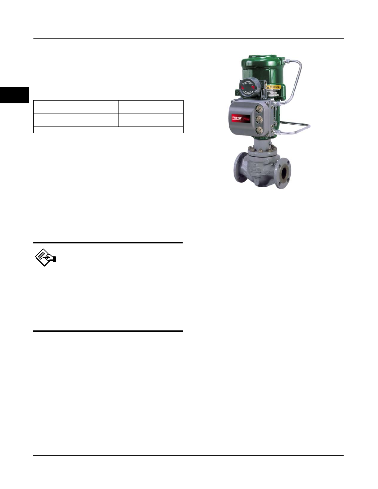
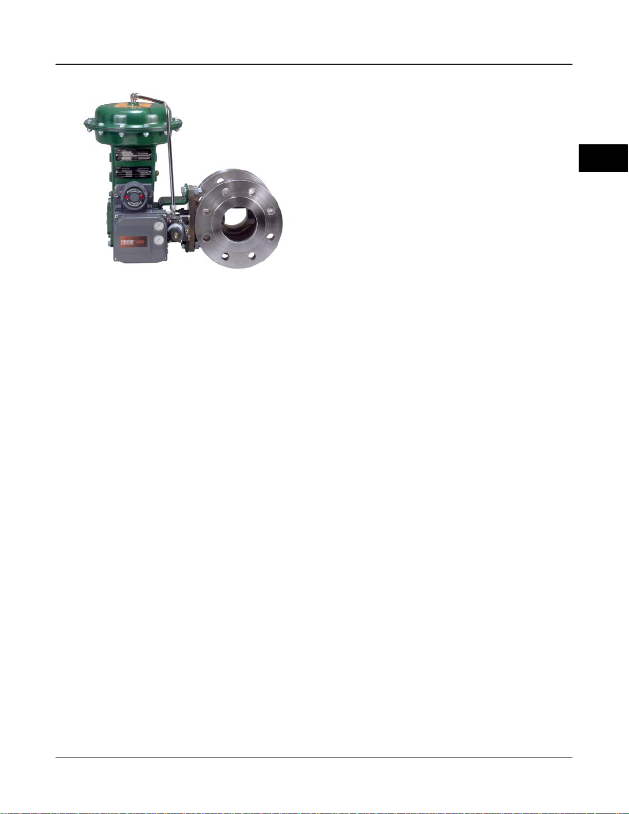
W9132-1
Figure 1-1. Type DVC6010f Digital Valve Controller
Mounted on Type 585C Piston Actuator
console, another FOUNDATION fieldbus system
console, or with AMS ValveLink Software.
DVC6000f Series digital valve controllers can be
mounted on single or double-acting sliding-stem
actuators, as shown in figure 1-1, or on rotary
actuators, as shown in figure 1-2. DVC6000f Series
digital valve controllers mount on most Fisher and
other manufacturers’ rotary and sliding-stem
actuators.
DVC6000f Series digital valve controllers are available
with several selections of control and diagnostic
capability. Control selections include:
Standard Control (SC)— Digital valve
controllers with Standard Control have the AO, PID,
ISEL, OS, AI, MAI, DO, and four DI function blocks in
addition to the resource and transducer blocks.
Instrument Description
DVC6000f Series digital valve controllers for
FOUNDATION fieldbus are interoperable,
communicating, microprocessor-based,
digital-to-pneumatic instruments. In addition to the
primary function of converting a digital input signal to a
pneumatic output, the DVC6000f Series digital valve
controller, using
communications protocol, gives easy access to
information critical to process operation as well as
process control. This can be done using a DeltaV
FOUNDATION fieldbus
1-2
Fieldbus Control (FC)—Digital valve controllers
with Fieldbus Control have the AO function block in
addition to the resource and transducer blocks.
Fieldbus Logic (FL)—Digital valve controllers
with Fieldbus Logic have the DO, and four DI function
blocks, in addition to the resource and transducer
block.
The diagnostic capabilities include:
Performance Diagnostics (PD)
Advanced Diagnostics (AD)
Fieldbus Diagnostics (FD)
March 2006
Page 17
W8115-FF
Figure 1-2. Rotary Control Valve with Type DVC6020f Digital
Valve Controller
Introduction
Analog Output (AO) Function Block—The
analog output function block accepts the output from
another function block (such as a PID block) and
transfers it as an actuator control signal to the
transducer block. If the DO block is selected, the AO
block is not functional.
1
Proportional-Integral-Derivative (PID)
Function Block—The PID function block performs
proportional-plus-integral-plus-derivative control.
Input Selector (ISEL) Function block—The
input selector function block selects from up to four
inputs and may provide the selected signal as input to
the PID block. The input selection can be configured
to select the first good input signal; a maximum,
minimum or average value; or a hot spare.
Performance and Advanced Diagnostics are available
with AMS ValveLink Software. They provide visibility
to instrument alerts. Fieldbus Diagnostics can be
viewed with any host system.
Instrument Blocks
The digital valve controller is a block-based device.
For detailed information on the blocks within the digital
valve controller, see the Detailed Setup / Blocks
section of this manual.
All DVC6000f Series digital valve controllers include
the resource and transducer block:
Resource Block—The resource block contains
the hardware specific characteristics associated with a
device; it has no input or output parameters. The
resource block monitors and controls the general
operation of other blocks within the device. For
example, when the mode of the resource block is Out
of Service, it impacts all function blocks.
Transducer Block—The transducer block
connects the analog output function block to the I/P
converter, relay, and travel sensor hardware within the
digital valve controller.
Output Splitter (OS) Function Block—The
output splitter function block accepts the output from
another function block (such as a PID block) and
creates two outputs that are scaled or split, according
to the user configuration. This block is typically used
for split ranging of two control valves.
Analog Input (AI) Function Block—The analog
input function block monitors the signal from a
DVC6000f sensor or internal measurement and
provides it to another block.
Multiple Analog Input (AI) Function
Block—The Multiple Analog Input (MAI) function block
has the ability to process up to eight DVC6000f
measurements and make them available to other
function blocks.
Discrete Output (DO) Function Block—The
discrete output function block processes a discrete set
point and sends it to a specified output channel, which
can be transferred to the transducer block for actuator
control. In the digital valve controller, the discrete
output block provides both normal open/closed control
and the ability to position the valve in 5% increments
for course throttling applications. If the AO block is
selected, the DO block is not functional.
Function Blocks
In addition to the resource and transducer block, the
digital valve controller may contain the following
function blocks. For additional information on function
blocks, refer to Appendix B,
Communication.
March 2006
FOUNDATION fieldbus
Discrete Input (DI) Function Block—The
discrete input function block processes a single
discrete input from a DVC6000f and makes it available
to other function blocks. In the digital valve controller,
the discrete input function block can provide limit
switch functionality and valve position proximity
detection.
1-3
Page 18

DVC6000f Series
Using This Manual
Procedures that require the use of the Model 375 Field
Communicator have the Field Communicator symbol
in the heading.
Also included is the path required to accomplish
1
various tasks; the sequence of steps through the Field
Communicator menus. For example, the path to
Resource Block Mode is RB > Setup > Res Block
Mode.
An overview of the Model 375 Field Communicator
resource block and transducer block menu structures
are shown at the beginning of this manual. Menu
structures for the function blocks are included with
each function block section in Detailed Setup / Blocks.
Throughout this document, parameters are typically
referred to by their common name or label, followed by
the parameter name and index number; for example,
Write Priority (WRITE_PRI [39]). However, not all
interface systems support the use of the parameter
label and instead use only the Parameter Name,
followed by the index number, when referring to the
block parameters.
Related Documents
Other documents containing information related to the
DVC6000f Series digital valve controllers include:
FIELDVUE
Controller (Bulletin 62.1:DVC6000f)
FIELDVUE
Controllers Quick Start Guide - Form 5778
AMS ValveLink Help or Documentation
DeltaV Online Help or documentation
www.fieldvue.com
DVC6000f Series Digital Valve
DVC6000f Series Digital Valve
Specifications
Specifications for the DVC6000f Series digital valve
controllers are shown in table 1-1.
Related Information
Fieldbus Installation and Wiring Guidelines
This manual describes how to connect the fieldbus to
the digital valve controller. For a technical description,
planning, and installation information for a
FOUNDATION fieldbus, refer to the FOUNDATION
Fieldbus Technical Overview available from the
Fieldbus
DeltaV System available from your Emerson Process
Management sales office.
FOUNDATION and Fieldbus Installations in a
Educational Services
For information on available courses for DVC6000f
Series digital valve controllers, as well as a variety of
other products, contact:
Emerson Process Management
Educational Services, Registration
P.O. Box 190; 301 S. 1st Ave.
Marshalltown, IA 50158−2823
Phone: 800−338−8158 or
Phone: 641−754−3771
FAX: 641−754−3431
e-mail: education@emersonprocess.com
1-4
March 2006
Page 19

Table 1-1. Specifications
Introduction
Available Configurations
Type DVC6010f: Sliding stem applications
Type DVC6020f: Rotary and long-stroke
sliding-stem applications [over 102 mm (4-inch)
travel]
Type DVC6030f: Quarter-turn rotary applications
Remote-Mounted Instrument
(1)
DVC6005f: Base unit for 2-inch pipestand or wall
mounting
DVC6015: Feedback unit for sliding-stem
applications
DVC6025: Feedback unit for rotary or long-stroke
sliding-stem applications
DVC6035: Feedback unit for quarter-turn rotary
applications
DVC6000f Series digital valve controllers can be
mounted on Fisher and other manufacturers rotary
and sliding-stem actuators.
Function Block Suites
Standard Control (throttling control)
Includes AO, PID, ISEL, OS, AI, MAI, DO, and four
DI function blocks
Fieldbus Control (throttling control)
Contains the AO function block
Fieldbus Logic [discrete on/off]
Includes DO, and four DI function blocks
Digital Communication Protocol
F
OUNDATION fieldbus registered device
Physical Layer Type(s):
121—Low−power signaling, bus−powered, Entity
Model I.S.
511—Low−power signaling, bus−powered, FISCO
I.S.
Output Signal
(2)
Pneumatic signal as required by the actuator, up to
full supply pressure.
Minimum Span: 0.4 bar (6 psig)
Maximum Span: 9.5 bar (140 psig)
Action: Double, Single direct, and Single reverse
Supply Pressure
(2,6)
Recommended: 0.3 bar (5 psi) higher than
maximum actuator requirements, up to maximum
supply pressure
Maximum: 10 bar (145 psig) or maximum pressure
rating of the actuator, whichever is lower
Steady-State Air Consumption
Standard Relay: At 1.4 bar (20 psig) supply
pressure: Less than 0.38 normal m
At 5.5 bar (80 psig) supply pressure: Less than 1.3
normal m
3
/hr (49 scfh)
Low Bleed Relay: At 1.4 bar (20 psig) supply
pressure: Average value 0.056 normal m
(2,3,4)
3
/hr (14 scfh)
3
/hr
(2.1 scfh)
At 5.5 bar (80 psig) supply pressure: Average value
0.184 normal m
3
/hr (6.9 scfh)
1
Block Execution Times
AO Block: 25 ms AI Block: 25 ms
PID Block: 30 ms MAI BLock: 40 ms
ISEL Block: 25 ms DO Block: 25 ms
OS Block: 25 ms DI Block: 20 ms
Electrical Input
Voltage Level: 9 to 32 volts
Maximum Current: 18 mA
Reverse Polarity Protection: Unit is not polarity
sensitive
Termination: Bus must be properly terminated per
ISA SP50 guidelines
March 2006
Maximum Output Capacity
Independent Linearity
Electromagnetic Interference (EMI)
−continued−
(3,4)
At 1.4 bar (20 psig) supply pressure:
10.0 normal m3/hr (375 scfh)
At 5.5 bar (80 psig) supply pressure:
29.5 normal m
3
/hr (1100 scfh)
(2,5)
±0.5% of output span
Tested per IEC 61326-1 (Edition 1.1). Meets
emission levels for Class A equipment (industrial
locations) and Class B equipment (domestic
locations). Meets immunity requirements for
industrial locations (Table A.1 in the IEC
specification document). Immunity performance is
shown in table 1-2.
1-5
Page 20

DVC6000f Series
Table 1-1. Specifications (continued)
Operating Ambient Temperature Limits
−40 to 80C (−40 to 176F) for most approved
valve-mounted instruments.
−40 to 125C (−40 to 257F) for remote-mounted
1
feedback unit.
−52 to 80C (−62 to 176F) for valve-mounted
instruments utilizing the Extreme Temperature
option (fluorosilicone elastomers)
Electrical Classification
Explosion proof, Division 2,
Dust-Ignition proof, Intrinsic Safety,
and FISCO
Explosion proof, Non-incendive,
APPROVED
ATEX
IECEx
Dust-Ignition proof, Intrinsic Safety,
and FISCO
Flameproof, Type n, Intrinsic Safety,
and FISCO
Flameproof, Type n, Intrinsic Safety,
and FISCO
Refer to Special Instructions for Safe Use and
Installation in Hazardous Locations in section 2,
tables 1-3, 1-4, 1-5, and 1-6, and figures D-1, D-2,
D-3, D-4, D-5, D-6, D-7, D-8, D-9 and D-10 for
specific approval information.
Electrical Housing: NEMA 4X, CSA Type 4X, IEC
60529 IP66
Connections
Supply Pressure: 1/4-inch NPT female and
integral pad for mounting 67CFR regulator
Output Pressure: 1/4-inch NPT female
Tubing: 3/8-inch metal, recommended
Vent: 3/8-inch NPT female
Electrical: 1/2-inch NPT female, M20 adapter
optional
Stem Travel
DVC6010f, DVC6015:
0 to 102 mm (4-inches) maximum
0 to 9.5 mm (0.375 inches) minimum
DVC6020f, DVC6025:
0 to 606 mm (23.875 inches) maximum
(6)
Shaft Rotation (DVC6020f, DVC6025, DVC6030f
and DVC6035)
0 to 50 degrees minimum
0 to 90 degrees maximum
Mounting
Designed for direct actuator mounting or remote
pipestand or wall mounting. Mounting the
instrument vertically, with the vent at the bottom of
the assembly, or horizontally, with the vent pointing
down, is recommended to allow drainage of
moisture that may be introduced via the instrument
air supply.
Weight
Valve-Mounted Instruments
Aluminum: 3.5 Kg (7.7 lbs)
Stainless Steel: 7.7 Kg (17 lbs)
Remote-Mounted Instruments
DVC6005f Base Unit: 4.1 Kg (9 lbs)
DVC6015 Feedback Unit: 1.3 Kg (2.9 lbs)
DVC6025 Feedback Unit: 1.4 Kg (3.1 lbs)
DVC6035 Feedback Unit: 0.9 Kg (2.0 lbs)
Options
Supply and output pressure gauges or Tire
valves, Integral mounted filter regulator,
Stainless steel housing, module base and
terminal box (valve-mounted instruments only)
Declaration of SEP
Fisher Controls International LLC declares this
product to be in compliance with Article 3 paragraph
3 of the Pressure Equipment Directive (PED) 97 /
23 / EC. It was designed and manufactured in
accordance with Sound Engineering Practice (SEP)
and cannot bear the CE marking related to PED
compliance.
However, the product may bear the CE marking to
indicate compliance with other applicable EC
Directives.
1. 3-conductor shielded cable, 22 AWG minimum wire size, is recommended for connection between base unit and feedback unit. Pneumatic tubing between base unit output connection
and actuator has been tested to 15 meters (50 feet) maximum without performance degradation.
2. Defined in ISA Standard S51.1.
3. Normal m3/hour − Normal cubic meters per hour at 0C and 1.01325 bar, absolute. Scfh − Standard cubic feet per hour at 60F and 14.7 psia.
4. Values at 1.4 bar (20 psig) based on a single-acting direct relay; values at 5.5 bar (80 psig) based on double-acting relay.
5. Typical value. Not applicable for travels less than 19 mm (0.75 inch) or for shaft rotation less than 60 degrees. Also, not applicable to Type DVC6020f digital valve controllers in long-stroke
applications.
6. The pressure/temperature limits in this manual and any applicable code or standard should not be exceeded.
1-6
March 2006
Page 21

Introduction
Table 1-2. Immunity Performance
Port Phenomenon Basic Standard Performance Criteria
Electrostatic discharge (ESD) IEC 61000-4-2 A
Enclosure
I/O signal/control
1. A = No degradation during testing. B = Temporary degradation during testing, but is self-recovering.
Radiated EM field IEC 61000-4-3 A
Rated power frequency magnetic field IEC 61000-4-8 A
Burst IEC 61000-4-4 A
Surge IEC 61000-4-5 A
Conducted RF IEC 61000-4-6 A
Table 1-3. Hazardous Area Classifications for Canada (CSA)
CERTIFICATION
BODY
CSA
TYPE
DVC60x0F
DVC60x0FS
(x = 1,2,3)
DVC6005F
DVC60x5
(x = 1,2,3)
CERTIFICATION OBTAINED ENTITY RATING
(Intrinsic Safety)
Class/Division
Class I,II,III Division 1 GP A,B,C,
D,E,F,G per drawing GE04331
(including FISCO)
V
= 30 Vdc
max
= 226 mA
I
max
= 5 nF
C
i
L
= 0 mH
i
V
= 17.5 Vdc
max
= 380 mA
I
max
Ci = 5 nF
Li = 0 mH
FIELDBUS
FISCO
Pi = 5.32 W
(Explosion Proof)
Class/Division
Class I Division 1 GP B,C,D
Class I Division 2 GP A,B,C,D
Class II Division 1 GP E,F,G
Class III Division 1
(Intrinsic Safety)
Class/Division
Class I,II,III Division 1 GP A,B,C,
D,E,F,G per drawing GE07476
(including FISCO)
(Explosion Proof)
Class/Division
Class I Division 1 GP C,D
Class I Division 2 GP A,B,C,D
Class II Division 1 GP E,F,G
Class III Division 1
(Intrinsic Safety)
Class/Division
Class I,II,III Division 1 GP A,B,C,
D,E,F,G per drawing GE07476
(Explosion Proof)
Class/Division
Class I Division 1 GP B,C,D
Class I Division 2 GP A,B,C,D
Class II Division 1 GP E,F,G
Class III Division 1
V
= 30 Vdc
max
I
= 226 mA
max
= 5 nF
C
i
= 0 mH
L
i
V
= 17.5 Vdc
max
= 380 mA
I
max
= 5 nF
C
i
Li = 0 mH
V
= 10 Vdc
max
= 4 mA
I
max
= 0 nF
C
i
Li = 0 mH
− − −
− − −
FIELDBUS
FISCO
− − −
− − −
− − −
− − −
Voc = 8.6 Vdc
= 2.3 mA
I
sc
= 6.2 µF
C
a
L
= 100 mH
a
Voc = 8.6 Vdc
I
= 2.3 mA
sc
= 6.2 µF
C
a
La = 100 mH
TEMPERATURE
CODE
T5(T
v 80C)
amb
T5(T
v 80C)
amb
T6(T
v 80C)
amb
T6(T
v 60C)
amb
T6(T
v 60C)
amb
T6(T
v 60C)
amb
T4(Tamb v 125C)
T5(Tamb v 95C)
T6(Tamb v 80C)
T4(Tamb v 125C)
T5(Tamb v 95C)
T6(Tamb v 80C)
T4(Tamb v 125C)
T5(Tamb v 95C)
T6(Tamb v 80C)
(1)
1
ENCLOSURE
RATING
4X
4X
4X
4X
4X
4X
4X
March 2006
1-7
Page 22

DVC6000f Series
CERTIFICATION
BODY
1
FM
TYPE
DVC60x0F
DVC60x0FS
(x = 1,2,3)
DVC6005F
DVC60x5
(x = 1,2,3)
Table 1-4. Hazardous Area Classifications for United States (FM)
CERTIFICATION OBTAINED ENTITY RATING
(Intrinsic Safety)
Class/Division
Class I,II,III Division 1 GP
A,B,C,D,E,F,G per drawing
GE04332 (including FISCO)
(Explosion Proof)
Class/Division
Class I, Division 1 GP B,C,D
Class I Division 2 GP A,B,C,D
Class II,III Division 1 GP E,F,G
Class II,III Division 2 GP F,G
(Intrinsic Safety)
Class/Division
Class I,II,III Division 1 GP
A,B,C,D,E,F,G per drawing
GE07475 (including FISCO)
(Explosion Proof)
Class/Division
Class I Division 1 GP C,D
Class I Division 2 GP A,B,C,D
Class II,III Division 1 GP E,F,G
Class II,III Division 2 GP F,G
(Intrinsic Safety)
Class/Division
Class I,II,III Division 1 GP A,B,C,
D,E,F,G per drawing GE07475
(Explosion Proof)
Class/Division
Class I Division 1 GP A,B,C,D
Class I Division 2 GP A,B,C,D
Class II,III Division 1 GP E,F,G
Class II,III Division 2 GP F,G
V
= 24 Vdc
max
I
= 226 mA
max
= 5 nF
C
i
L
= 0 mH
i
P
= 1.4 W
i
V
= 17.5 Vdc
max
I
= 380 mA
max
= 5 nF
C
i
L
= 0 mH
i
= 5.32 W
P
i
− − −
− − −
V
= 24 Vdc
max
= 226 mA
I
max
= 5 nF
C
i
Li = 0 mH
P
= 1.4 W
i
V
= 17.5 Vdc
max
= 380 mA
I
max
= 5 nF
C
i
L
= 0 mH
i
= 5.32 W
P
i
− − −
− − −
V
= 10 Vdc
max
= 4 mA
I
max
= 0 nF
C
i
Li = 0 mH
= 10 mW
P
i
− − −
− − −
FIELDBUS
FISCO
FIELDBUS
Voc = 8.6 Vdc
I
sc
C
La = 100 mH
P
o
FISCO
Voc = 8.6 Vdc
I
sc
C
L
a
P
o
= 2.3 mA
= 6.2 µF
a
= 5 mH
= 2.3 mA
= 6.2 µF
a
= 100 mH
= 5 mW
TEMPERATURE
CODE
T5(T
v 80C)
amb
T6(T
v 80C)
amb
T6(T
v 80C)
amb
T6(T
v 60C)
amb
T6(T
v 60C)
amb
T6(T
v 60C)
amb
T4(Tamb v 125C)
T5(Tamb v 95C)
T6(Tamb v 80C)
T4(Tamb v 125C)
T5(Tamb v 95C)
T6(Tamb v 80C)
T4(Tamb v 125C)
T5(Tamb v 95C)
T6(Tamb v 80C)
ENCLOSURE
RATING
4X
4X
4X
4X
4X
4X
4X
4X
4X
1-8
March 2006
Page 23

CERTIFICATE TYPE
DVC60x0F
DVC60x0FS
(x = 1,2,3)
ATEX
DVC6005F
DVC60x5
(x = 1,2,3)
Table 1-5. Hazardous Area Classifications—ATEX
CERTIFICATION OBTAINED ENTITY RATING
II 1 G D
Gas
EEx ia IIC T5/T6 - Intrinsic Safety
Dust
T85C (Tamb v 80C)
II 2 G D
Gas
EEx d IIB+H2 T5/T6 - Flameproof
Dust
T90C (Tamb v 85C)
II 3 G D
Gas
EEx nCL IIC T5/T6 - Type n
Dust
T85C (Tamb v 80C)
II 1 G D
Gas
EEx ia IIC T5/T6 - Intrinsic Safety
Dust
T85C (Tamb v 80C)
II 2 G D
Gas
EEx d IIB T5/T6 - Flameproof
Dust
T90C (Tamb v 80C)
II 3 G D
Gas
EEx nL IIC T5/T6 - Type n
Dust
T85C (Tamb v 80C)
II 1 G D
Gas
EEx ia IIC T4/T5/T6 - Intrinsic Safety
Dust
T130C (Tamb v 125C)
II 2 G D
Gas
EEx d IIC T4/T5/T6 - Flameproof
Dust
T130C (Tamb v 125C)
II 3 G D
Gas
EEx nA IIC T4/T5/T6 - Type n
Dust
T130C (Tamb v 125C)
Ui = 24 Vdc
= 226 mA
I
i
Ci = 5 nF
= 0 mH
L
i
Pi = 1.4 W
U
= 17.5 Vdc
i
I
= 380 mA
i
= 5 nF
C
i
= 0 mH
L
i
P
= 5.32 W
i
Ui = 24 Vdc
Ii = 226 mA
= 5 nF
C
i
= 0 mH
L
i
Pi = 1.4 W
Ui = 17.5 Vdc
Ii = 380 mA
= 5 nF
C
i
Li = 0 mH
P
= 5.32 W
i
Ui = 10 Vdc
Ii = 4 mA
= 0 nF
C
i
L
= 0 mH
i
= 5 mW
P
i
FIELDBUS
FISCO
− − −
− − −
FIELDBUS
FISCO
− − −
− − −
− − −
− − −
Uo = 8.6 Vdc
Io = 2.3 mA
= 6.2 µF
C
a
= 100 mH
L
a
Po = 5 mW
Uo = 8.6 Vdc
Io = 2.3 mA
= 6.2 µF
C
a
La = 100 mH
P
= 5 mW
o
Introduction
TEMPERATURE
CODE
T5(T
v 80C)
amb
v75C)
T6 (T
amb
T5(T
v 80C)
amb
v 75C)
T6 (T
amb
T5(T
v 80C)
amb
v 75C)
T6 (T
amb
T5(T
v 80C)
amb
v 75C)
T6 (T
amb
T5(T
v 80C)
amb
v 75C)
T6 (T
amb
T5(T
v 80C)
amb
v 75C)
T6 (T
amb
T4(Tamb v 125C)
T5(Tamb v 95C)
T6(Tamb v 80C)
T4(Tamb v 125C)
T5(Tamb v 95C)
T6(Tamb v 80C)
T4(Tamb v 125C)
T5(Tamb v 95C)
T6(Tamb v 80C)
ENCLOSURE
RATING
IP66
IP66
IP66
IP66
IP66
IP66
IP66
IP66
IP66
1
March 2006
1-9
Page 24

DVC6000f Series
CERTIFICATE TYPE
1
DVC60x0F
DVC60x0FS
(x = 1,2,3)
IECEx
DVC6005F
DVC60x5
(x = 1,2,3)
Table 1-6. Hazardous Area Classifications—IECEx
CERTIFICATION OBTAINED ENTITY RATING
Gas
Ex ia IIC T5/T6 - Intrinsic Safety
Gas
Ex d IIB+H2 T5/T6 - Flameproof
Gas
Ex nC IIC T5/T6 - Type n
Gas
Ex ia IIC T5/T6 - Intrinsic Safety
Gas
Ex d IIB T5/T6 - Flameproof
Gas
Ex nC IIC T5/T6 - Type n
Gas
Ex ia IIC T4/T5/T6 - Intrinsic Safety
Gas
Ex d IIC T4/T5/T6 - Flameproof
Gas
Ex nA IIC T4/T5/T6 - Type n
V
= 24 Vdc
max
I
= 226 mA
max
= 5 nF
C
i
= 0 mH
L
i
P
= 1.4 W
i
V
= 17.5 Vdc
max
I
= 380 mA
max
= 5 nF
C
i
= 0 mH
L
i
P
= 5.32 W
i
V
= 24 Vdc
max
= 226 mA
I
max
= 5 nF
C
i
L
= 0 mH
i
= 1.4 W
P
i
V
= 17.5 Vdc
max
= 380 mA
I
max
= 5 nF
C
i
= 0 mH
L
i
Pi = 5.32 W
V
= 10 Vdc
max
I
= 4 mA
max
= 0 nF
C
i
Li = 0 mH
= 10 mW
P
i
FIELDBUS
FISCO
− − −
− − −
FIELDBUS
FISCO
− − −
− − −
− − −
− − −
Voc = 8.6 Vdc
= 2.3 mA
I
sc
= 6.2 µF
C
a
L
= 100 mH
a
= 5 mH
P
o
Voc = 8.6 Vdc
= 2.3 mA
I
sc
= 6.2 µF
C
a
= 100 mH
L
a
Po = 5 mH
TEMPERATURE
CODE
T5(T
v 80C)
amb
v 75C)
T6 (T
amb
T5(T
v 80C)
amb
v 75C)
T6 (T
amb
T5(T
v 80C)
amb
v 75C)
T6 (T
amb
T5(T
v 80C)
amb
v 75C)
T6 (T
amb
T5(T
v 80C)
amb
v 75C)
T6 (T
amb
T5(T
v 80C)
amb
v 75C)
T6 (T
amb
T4(Tamb v 125C)
T5(Tamb v 95C)
T6(Tamb v 80C)
T4(Tamb v 125C)
T5(Tamb v 95C)
T6(Tamb v 80C)
T4(Tamb v 125C)
T5(Tamb v 95C)
T6(Tamb v 80C)
ENCLOSURE
RATING
IP66
IP66
IP66
IP66
IP66
IP66
IP66
IP66
IP66
1-10
March 2006
Page 25

2-2
Installation
Section 2 Installation
Special Instructions for Safe Use and
Installation in Hazardous Locations
CSA 2-3. . . . . . . . . . . . . . . . . . . . . . . . . . . . . . . . . . . . . . . . . . . . . . . . . . . . . . . . . . . . . . . . . . . . .
FM 2-3. . . . . . . . . . . . . . . . . . . . . . . . . . . . . . . . . . . . . . . . . . . . . . . . . . . . . . . . . . . . . . . . . . . . . .
ATEX Intrinsic Safety, Dust 2-3. . . . . . . . . . . . . . . . . . . . . . . . . . . . . . . . . . . . . . . . . . . . . . .
ATEX Flameproof, Dust 2-4. . . . . . . . . . . . . . . . . . . . . . . . . . . . . . . . . . . . . . . . . . . . . . . . . .
ATEX Type n, Dust 2-4. . . . . . . . . . . . . . . . . . . . . . . . . . . . . . . . . . . . . . . . . . . . . . . . . . . . . .
IECEx Instrinsic Safety, Type n, Flameproof 2-4. . . . . . . . . . . . . . . . . . . . . . . . . . . . . .
Mounting
Type DVC6010f on Sliding-Stem Actuators (up to 4 inches travel) 2-4. . . . . . . . .
Type DVC6020f on Long-Stroke Sliding-Stem Actuators
(4 to 24 inches travel) and Rotary Actuators
Type DVC6030f on Quarter-Turn Actuators 2-9. . . . . . . . . . . . . . . . . . . . . . . . . . . . . . .
Guidelines for Mounting Type DVC6005f Base Unit 2-10. . . . . . . . . . . . . . . . . . . . . . .
Wall Mounting 2-10. . . . . . . . . . . . . . . . . . . . . . . . . . . . . . . . . . . . . . . . . . . . . . . . . . . . . . . . . . .
Pipestand Mounting 2-12. . . . . . . . . . . . . . . . . . . . . . . . . . . . . . . . . . . . . . . . . . . . . . . . . . . . . .
Type DVC6015 on Sliding-Stem Actuators (up to 4 inches travel) 2-12. . . . . . . . . .
2
2-6. . . . . . . . . . . . . . . . . . . . . . . . . . . . . .
March 2006
Type DVC6025 on Long-Stroke Sliding-Stem Actuators
(4 to 24 inches travel) and Rotary Actuators
Type DVC6035 on Quarter-Turn Actuators 2-14. . . . . . . . . . . . . . . . . . . . . . . . . . . . . . . .
Pressure Control 2-15. . . . . . . . . . . . . . . . . . . . . . . . . . . . . . . . . . . . . . . . . . . . . . . . . . . . . . . . .
Actuator Mounting 2-16. . . . . . . . . . . . . . . . . . . . . . . . . . . . . . . . . . . . . . . . . . . . . . . . . . . . . . . .
67CFR Filter Regulator
Integral-Mounted Regulator 2-16. . . . . . . . . . . . . . . . . . . . . . . . . . . . . . . . . . . . . . . . . . . . . . . .
Yoke-Mounted Regulator 2-16. . . . . . . . . . . . . . . . . . . . . . . . . . . . . . . . . . . . . . . . . . . . . . . . . .
Casing-Mounted Regulator 2-16. . . . . . . . . . . . . . . . . . . . . . . . . . . . . . . . . . . . . . . . . . . . . . . .
Pressure Connections
Supply Connections 2-17. . . . . . . . . . . . . . . . . . . . . . . . . . . . . . . . . . . . . . . . . . . . . . . . . . . . .
Output Connections 2-18. . . . . . . . . . . . . . . . . . . . . . . . . . . . . . . . . . . . . . . . . . . . . . . . . . . . . .
Single-Acting Actuators 2-18. . . . . . . . . . . . . . . . . . . . . . . . . . . . . . . . . . . . . . . . . . . . . . . . . . .
Double-Acting Actuators 2-18. . . . . . . . . . . . . . . . . . . . . . . . . . . . . . . . . . . . . . . . . . . . . . . . . .
Vent Connections 2-18. . . . . . . . . . . . . . . . . . . . . . . . . . . . . . . . . . . . . . . . . . . . . . . . . . . . . . . . .
2-13. . . . . . . . . . . . . . . . . . . . . . . . . . . . . .
2-1
Page 26

DVC6000f Series
Electrical Connections 2-19. . . . . . . . . . . . . . . . . . . . . . . . . . . . . . . . . . . . . . . . . . . . . . . . .
Fieldbus Connections 2-19. . . . . . . . . . . . . . . . . . . . . . . . . . . . . . . . . . . . . . . . . . . . . . . . . . . .
Making Fieldbus Connections with a Twisted-Shielded Pair 2-20. . . . . . . . . . . . . . . . . . . .
Making Fieldbus Connections with a Quick Connect Cable Entry 2-20. . . . . . . . . . . . . . .
Feedback Unit Connections for Remote Mounting 2-21. . . . . . . . . . . . . . . . . . . . . . . . .
Communication Connections 2-24. . . . . . . . . . . . . . . . . . . . . . . . . . . . . . . . . . . . . . . . . . . . .
2
Simulate Enable Jumper 2-25. . . . . . . . . . . . . . . . . . . . . . . . . . . . . . . . . . . . . . . . . . . . . . . .
Commissioning Tag 2-25. . . . . . . . . . . . . . . . . . . . . . . . . . . . . . . . . . . . . . . . . . . . . . . . . . . .
2-2
March 2006
Page 27

Installation
Installation
WARNING
Avoid personal injury or property
damage from sudden release of
process pressure or bursting of parts.
Before mounting the DVC6000f Series
digital valve controller:
Always wear protective clothing
and eyewear when performing any
installation procedures.
Disconnect any operating lines
providing air pressure, electric power,
or a control signal to the actuator. Be
sure the actuator cannot suddenly
open or close the valve.
Use bypass valves or completely
shut off the process to isolate the
valve from process pressure. Relieve
process pressure from both sides of
the valve.
Vent the pneumatic actuator
loading pressure and relieve any
actuator spring precompression.
Use lock-out procedures to be
sure that the above measures stay in
effect while you work on the
equipment.
Check with your process or
safety engineer for any additional
measures that must be taken to
protect against process media.
Special Instructions for Safe Use and Installation in Hazardous Locations
Certain nameplates may carry more than one
approval, and each approval may have unique
installation requirements and/or conditions of safe-use.
Special instructions are listed by agency/approval
below.
After reading and understanding these special
conditions of use, proceed with standard installation
procedures.
WARNING
Failure to follow these conditions of
safe-use could result in personal injury
or property damage from fire or
explosion, and area re-classification.
CSA
Special Conditions of Safe Use
No special conditions for safe use.
Refer to table 1-3 for approval information, figures D-1
and D-2 for CSA loop schematics, and figure D-3 for
the CSA nameplates.
FM
Special Conditions of Safe Use
No special conditions for safe use.
Refer to table 1-4 for approval information, figures D-4
and D-5 for FM loop schematics, and figure D-6 for the
FM nameplates.
ATEX Intrinsic Safety, Dust
Special Conditions for Safe Use
Type DVC6000f Series, and Type DVC6005f
1. This apparatus can only be connected to an
intrinsically safe certified equipment and this
combination must be compatible as regards the
intrinsically safe rules.
2. The electrical parameters of this equipment must
not exceed any following values:
v 17.5 V; IO v380 mA; POv 5.32 W
U
O
3. Operating ambient temperature: −52C or −40C
to + 85C
Type DVC6015, DVC6025, and DVC6035
1. This apparatus can only be connected to an
instrinsically safe certified equipment and this
combination must be compatible as regards the
intrinsically safe rules.
Refer to table 1-5 for additional approval information,
and figure D-7 for the the ATEX Intrinsic Safety, Dust
nameplates.
2
March 2006
2-3
Page 28

DVC6000f Series
ATEX Flameproof, Dust
Special Conditions for Safe Use
Type DVC6000f Series
Operating ambient temperature: −52C or −40C to
+ 85C
Type DVC6005f and Type DVC6015, DVC6025,
2
and DVC6035
Operating ambient temperature as indicated on the
nameplate.
Refer to table 1-5 for additional approval information,
and figure D-8 for the ATEX Flameproof, Dust
nameplates.
ATEX Type n, Dust
Special Conditions for Safe Use
Type DVC6000f Series
Operating ambient temperature: −52C or −40C to
+ 80C
Type DVC6005f and Type DVC6015, DVC6025,
and DVC6035
Operating ambient temperature as indicated on the
nameplate.
Refer to table 1-5 for additional approval information,
and figure D-9 for the ATEX Type n, Dust nameplates.
IECEx Intrinsic Safety, Type n, Flameproof
Conditions of Certification
Type DVC6000f Series, and Type DVC6005f
Ex ia / Ex d / Ex n
1. Warning: Electrostatic charge hazard. Do not rub or
clean with solvents. To do so could result in an
explosion.
Type DVC6000f Series, Type DVC6005f, and Type
DVC6005f and Type DVC6015, DVC6025, and
DVC6035
EX d / Ex n
2. Do not open while energized.
Refer to table 1-6 for additional approval information,
and figure D-10 for the IECEx nameplates.
Mounting
Type DVC6010f on Sliding-Stem Actuators Up to 102 mm (4 Inches) of Travel
WARNING
Refer to the Installation WARNING at
the beginning of this section.
If ordered as part of a control valve assembly, the
factory mounts the digital valve controller on the
actuator, makes pneumatic connections to the
actuator, sets up, and calibrates the instrument. If you
purchased the digital valve controller separately, you
will need a mounting kit to mount the digital valve
controller on the actuator. See the instructions that
come with the mounting kit for detailed information on
mounting the digital valve controller to a specific
actuator model.
The Type DVC6010f digital valve controller mounts on
sliding-stem actuators with up to 102 mm (4-inch)
travel. Figure 2-1 shows a typical mounting on an
actuator with up to 51 mm (2-inch) travel. Figure 2-2
shows a typical mounting on actuators with 51 to 102
mm (2- to 4-inch) travel. For actuators with greater
than 102 mm (4-inch) travel, see the guidelines for
mounting a Type DVC6020f digital valve controller.
Refer to the following guidelines when mounting on
sliding-stem actuators with up to 4 inches of travel.
Where a key number is referenced, refer to
figure 11-2.
1. Isolate the control valve from the process line
pressure and release pressure from both sides of the
valve body. Shut off all pressure lines to the actuator,
releasing all pressure from the actuator. Use lock-out
procedures to be sure that the above measures stay in
effect while you work on the equipment.
2. Attach the connector arm to the valve stem
connector.
3. Attach the mounting bracket to the digital valve
controller housing.
4. If valve travel exceeds 2 inches, a feedback arm
extension is attached to the existing 2-inch feedback
arm. Remove the existing bias spring (key 78) from
the 2-inch feedback arm (key 79). Attach the feedback
arm extension to the feedback arm (key 79) as shown
in figure 2-2.
5. Mount the digital valve controller on the actuator as
described in the mounting kit instructions.
6. Set the position of the feedback arm (key 79) on
the digital valve controller to the zero drive position
2-4
March 2006
Page 29

29B1674-A / DOC
29B3403-A
Installation
CAP SCREW, FLANGED
2
MACHINE SCREW
SHIELD
ADJUSTMENT ARM
CONNECTOR ARM
CAP SCREW
PLAIN WASHER
Figure 2-1. Type DVC6010f Digital Valve Controller Mounted on Sliding-Stem Actuators with up to 2 Inches Travel
HEX NUT
CONNECTOR ARM
CAP SCREW, FLANGED
MACHINE SCREW,
LOCK WASHER,
HEX NUT
FEEDBACK ARM
EXTENSION,
BIAS SPRING
ADJUSTMENT ARM
MACHINE SCREW, FLAT
HEAD
MACHINE SCREW
SHIELD
LOCK WASHER
SPACER
HEX NUT, FLANGED
LOCK WASHER
PLAIN WASHER
Figure 2-2. Type DVC6010f Digital Valve Controller Mounted on Sliding-Stem Actuators with 2 to 4 Inches Travel
March 2006
2-5
Page 30
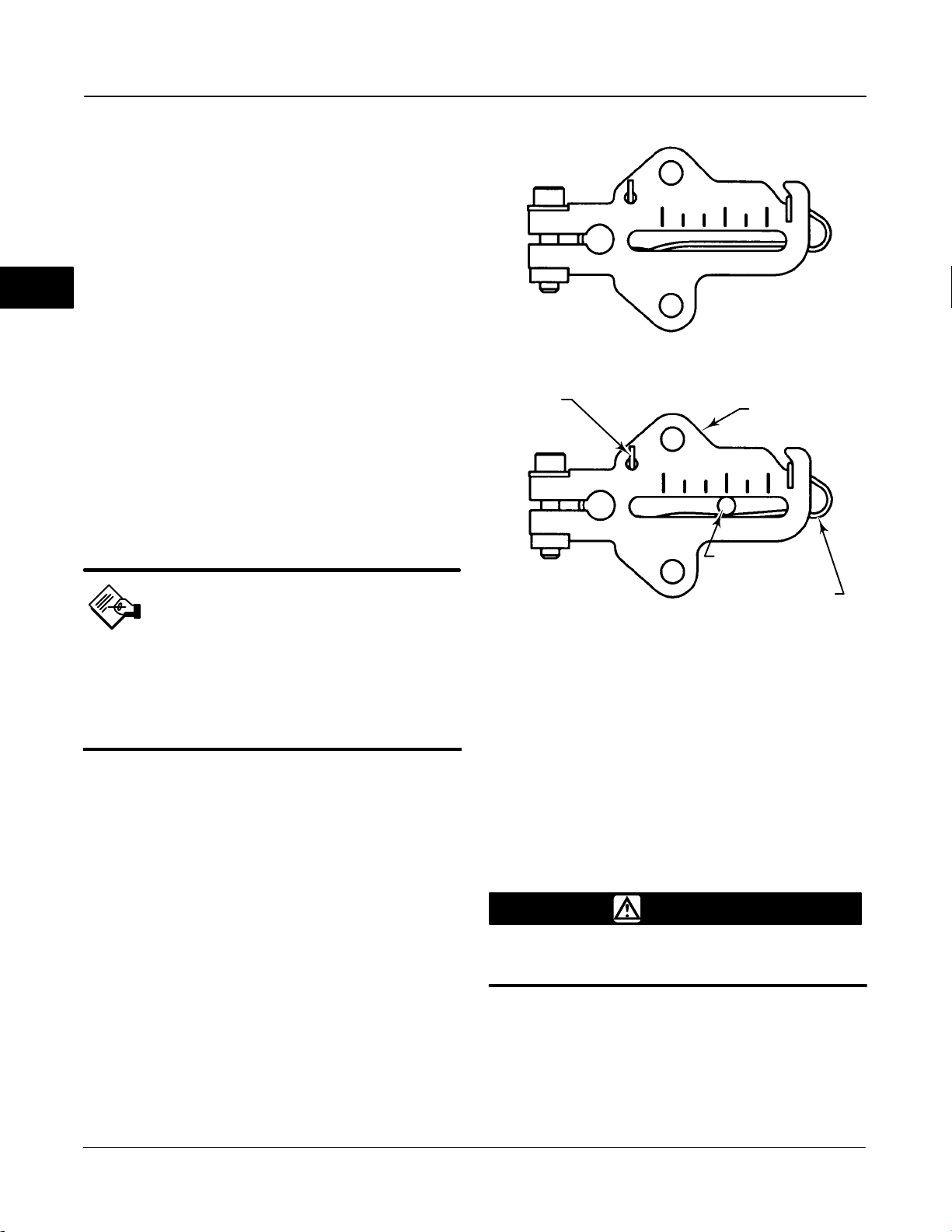
DVC6000f Series
(zero pressure from Port A with Relay Type A) by
inserting the alignment pin (key 46) through the hole
on the feedback arm as follows:
For air-to-open actuators (i.e., the actuator
stem retracts into the actuator casing or cylinder as air
pressure to the casing or lower cylinder increases),
insert the alignment pin into the hole marked ‘‘A’’. For
this style actuator, the feedback arm rotates
2
counterclockwise, from A to B, as air pressure to the
casing or lower cylinder increases.
For air-to-close actuators (i.e., the actuator
stem extends from the actuator casing or cylinder as
air pressure to the casing or upper cylinder increases),
insert the alignment pin into the hole marked ‘‘B’’. For
this style actuator, the feedback arm rotates
clockwise, from B to A, as air pressure to the casing or
upper cylinder increases.
BIAS SPRING
SPRING RELAXED
FEEDBACK ARM
Note
When performing the following steps,
ensure there is enough clearance
between the adjustment arm and the
feedback arm to prevent interference
with the bias spring.
7. Apply lubricant to the pin of the adjustment arm. As
shown in figure 2-3, place the pin into the slot of the
feedback arm or feedback arm extension so that the
bias spring loads the pin against the side of the arm
with the valve travel markings.
8. Install the external lock washer on the adjustment
arm. Position the adjustment arm in the slot of the
connector arm and loosely install the flanged hex nut.
9. Slide the adjustment arm pin in the slot of the
connector arm until the pin is in line with the desired
valve travel marking. Tighten the flanged hex nut.
10. Remove the alignment pin (key 46) and store it in
the module base next to the I/P assembly.
11. After calibrating the instrument, attach the shield
with two machine screws.
ADJUSTMENT
ARM PIN
BIAS SPRING
SPRING UNDER TENSION OF
A7209/IL
Figure 2-3. Locating Adjustment Arm Pin in Feedback Arm
ADJUSTMENT ARM PIN
Type DVC6020f on Long-Stroke (4 to 24 Inch Travel) Sliding-Stem Actuators and Rotary Actuators
WARNING
Refer to the Installation WARNING at
the beginning of this section.
If ordered as part of a control valve assembly, the
factory mounts the digital valve controller on the
actuator, makes pneumatic connections to the
actuator, sets up, and calibrates the instrument. If you
purchased the digital valve controller separately, you
will need a mounting kit to mount the digital valve
2-6
March 2006
Page 31

Installation
CAM/ROLLER POSITION MARK
A
PLAIN WASHER
HEX NUT
STUD, CONT
THREAD
CAM
VENT
29B1665-A / DOC
SPACER
Figure 2-4. Type DVC6020f Digital Valve Controller Mounted on Long-Stroke Sliding-Stem Actuator.
A
controller on the actuator. See the instructions that
come with the mounting kit for detailed information on
mounting the digital valve controller to a specific
actuator model.
Note
All cams supplied with FIELDVUE
mounting kits are characterized to
provide a linear response.
Type DVC6020f digital valve controllers use a cam
(designed for linear response) and roller as the
feedback mechanism. Figure 2-4 shows an example of
mounting on sliding-stem actuators with travels from 4
inches to 24 inches. Some long-stroke applications will
require an actuator with a tapped lower yoke boss.
Figures 2-5 and 2-7 show the Type DVC6020f
mounted on rotary actuators.
As shown in figure 2-5, two feedback arms are
available for the digital valve controller. Most
long-stroke sliding-stem and rotary actuator
installations use the long feedback arm [62 mm (2.45
inches) from roller to pivot point]. Installations on
Fisher Type 1051 size 33 and Type 1052 size 20 and
33 actuators use the short feedback arm [54 mm (2.13
LOCK WASHER
CAP SCREW
CAP SCREW, HEX SOCKET
2
MOUNTING PLATE
STUD, CONT THREAD
HEX NUT
PLAIN WASHER
SECTION A-A
inches) from roller to pivot point]. Verify that the
correct feedback arm is installed on the digital valve
controller before beginning the mounting procedure.
Refer to figures 2-4, 2-5, and 2-7 for parts locations.
Refer to the following guidelines when mounting on
sliding-stem actuators with 4 to 24 inches of travel or
on rotary actuators:
1. Isolate the control valve from the process line
pressur and release pressure from both sides of the
valve body. Shut off all pressure lines to the
pneumatic actuator, releasing all pressure from the
actuator. Use lock-out procedures to be sure that the
above measures stay in effect while working on the
equipment.
2. If a cam is not already installed on the actuator,
install the cam as described in the instructions
included with the mounting kit. For sliding-stem
actuators, the cam is installed on the stem connector.
3. If a mounting plate is required, fasten the mounting
plate to the actuator.
4. For applications that require remote venting, a
pipe-away bracket kit is available. Follow the
instructions included with the kit to replace the existing
mounting bracket on the digital valve controller with
the pipe-away bracket and to transfer the feedback
parts from the existing mounting bracket to the
pipe-away bracket.
5. Larger size actuators may require a follower arm
extension, as shown in figure 2-7. If required, the
March 2006
2-7
Page 32

DVC6000f Series
2
MOUNTING ADAPTOR
CAP SCREW, HEX SOCKET
CAM
MACHINE SCREW
29B2094-A / DOC
TYPICAL MOUNTING WITH SHORT FEEDBACK ARM
(FISHER TYPE 1052 SIZE 33 ACTUATOR SHOWN)
Figure 2-5. Type DVC6020f Digital Valve Controller Mounted on Rotary Actuator
MACHINE SCREW
29B1672-A / DOC
CAM
TYPICAL MOUNTING WITH LONG FEEDBACK ARM
(FISHER TYPE 1061 SIZE 30−68 ACTUATOR SHOWN)
CAP SCREW,
HEX SOCKET
29B1703-A / DOC
MOUNTING BRACKET
SPACER
19B3879−A / DOC
FEEDBACK ARM
TRAVEL INDICATOR PIN
TRAVEL INDICATOR
Figure 2-6. Mounting a Type DVC6030f Digital Valve Controller on a Rotary Actuator (Type 1032 Size 425A Shown)
2-8
March 2006
Page 33

Installation
FOLLOWER ARM
EXTENSION
MACHINE SCREW,
LOCK WASHER,
HEX NUT
CAP SCREW,
HEX SOCKET
CAP SCREW
29B1673-A / DOC
Figure 2-7. Type DVC6020f Digital Valve Controller with Long
Feedback Arm and Follower Arm Extension Mounted on a
Rotary Actuator
CAM
follower arm extension is included in the mounting kit.
Follow the instructions included with the mounting kit
to install the follower arm extension.
6. Mount the Type DVC6020f on the actuator as
follows:
If ordered as part of a control valve assembly, the
factory mounts the digital valve controller on the
actuator, makes pneumatic connections to the
actuator, sets up, and calibrates the instrument. If you
purchased the digital valve controller separately, you
will need a mounting kit to mount the digital valve
controller on the actuator. See the instructions that
come with the mounting kit for detailed information on
mounting the digital valve controller to a specific
actuator model.
Figure 2-6 shows the Type DVC6030f digital valve
controller mounted on a quarter-turn actuator. Refer to
figure 2-6 for parts locations. Refer to the following
guidelines when mounting on quarter-turn actuators:
Note
Due to NAMUR mounting limitations,
do not use the heavier stainless steel
Type DVC6030f in vibration service.
2
If required, a mounting adaptor is included in the
mounting kit. Attach the adaptor to the actuator as
shown in figure 2-5. Then attach the digital valve
controller assembly to the adaptor. The roller on the
digital valve controller feedback arm will contact the
actuator cam as it is being attached.
If no mounting adaptor is required, attach the
digital valve controller assembly to the actuator or
mounting plate. The roller on the digital valve
controller feedback arm will contact the actuator cam
as it is being attached.
7. For long-stroke sliding-stem actuators, after the
mounting is complete, check to be sure the roller
aligns with the position mark on the cam (see
figure 2-4). If necessary, reposition the cam to attain
alignment.
Type DVC6030f on Quarter-Turn Actuators
WARNING
Refer to the Installation WARNING at
the beginning of this section.
1. Isolate the control valve from the process line
pressure and release pressure from both sides of the
valve body. Shut off all pressure lines to the pneumatic
actuator, releasing all pressure from the actuator. Use
lock-out procedures to be sure that the above
measures stay in effect while working on the
equipment.
2. If necessary, remove the existing hub from the
actuator shaft.
3. If a positioner plate is required, attach the
positioner plate to the actuator as described in the
mounting kit instructions.
4. If required, attach the spacer to the actuator shaft.
Refer to figures 2-8 and 2-9. The travel indicator
assembly can have a starting position of 7:30 or
10:30. Determine the desired starting position then
proceed with the next step. Considering the top of the
digital valve controller as the 12 o’clock position, in the
next step attach the travel indicator, so that the pin is
positioned as follows:
If increasing pressure from the digital valve
controller output A rotates the potentiometer shaft
clockwise (as viewed from the back of the
instrument), mount the travel indicator assembly such
that the arrow is in the 10:30 position, as shown in
figure 2-8.
March 2006
2-9
Page 34
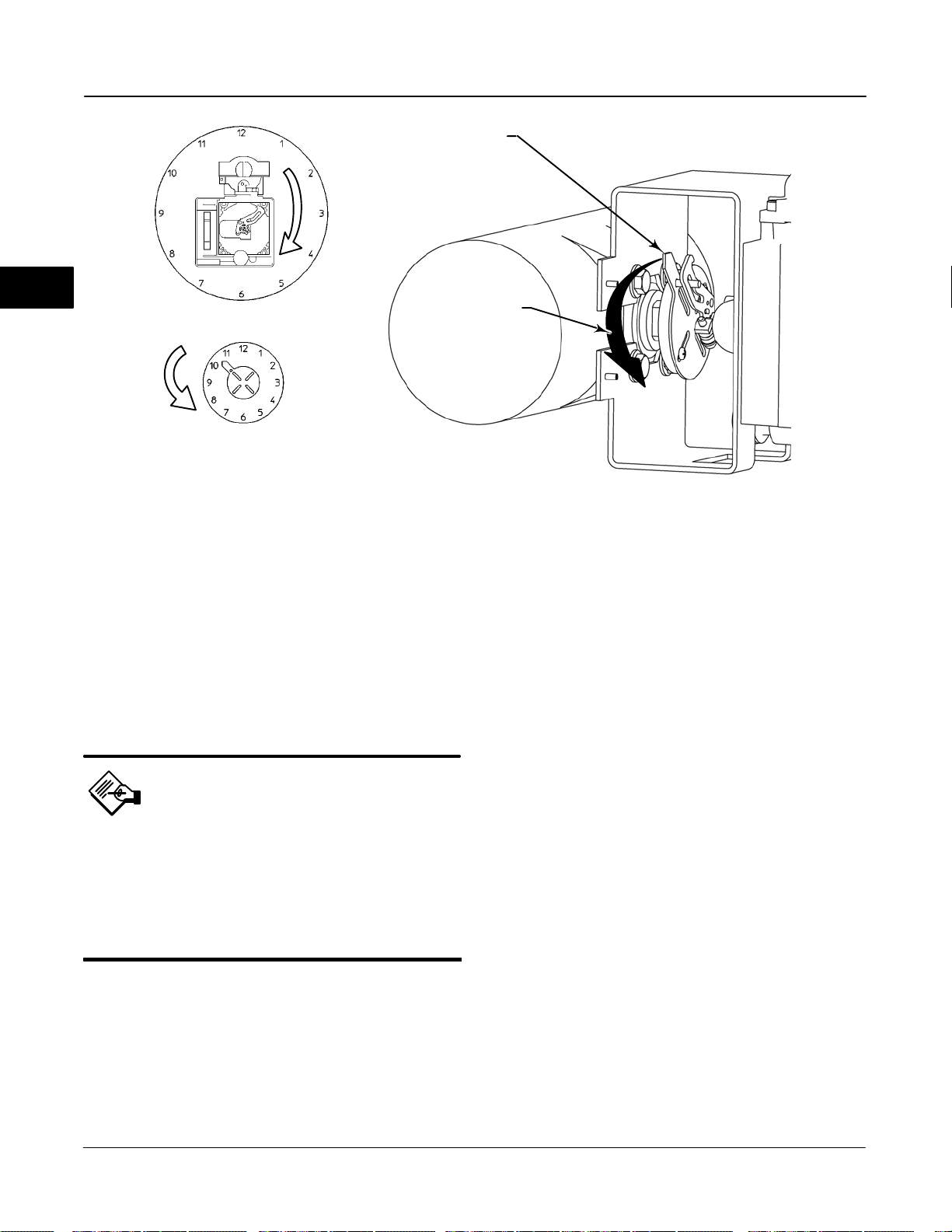
DVC6000f Series
E0989 / DOC
2
STARTING POSITION OF THE ACTUATOR TRAVEL
INDICATOR ASSEMBLY IF INCREASING PRESSURE
FROM OUTPUT A DRIVES THE INDICATOR
COUNTERCLOCKWISE (THE POTENTIOMETER
SHAFT WILL ROTATE CLOCKWISE AS VIEWED
FROM THE BACK OF THE FIELDVUE INSTRUMENT)
DVC6030f FEEDBACK
ARM MOVEMENT
ACTUATOR SHAFT MOVEMENT
STARTING POSITION OF TRAVEL
INDICATOR ASSEMBLY (DIGITAL
VALVE CONTROLLER OUTPUT A
AT 0 PSI. )
IN THIS POSITION, THE “B” HOLE
IN THE FEEDBACK ARM WILL BE
ALIGNED WITH THE REFERENCE
HOLE IN THE DIGITAL VALVE
CONTROLLERS HOUSING.
MOVEMENT OF TRAVEL
INDICATOR ASSEMBLY WITH
INCREASING PRESSURE FROM
OUTPUT A.
19B3879-A / DOC-1
Figure 2-8. Explanation of Travel Indicator Starting Position and Movement, if Clockwise Orientation is Selected for
“Travel Sensor Motion” in AMS ValveLink
If increasing pressure from the digital valve
controller output A rotates the potentiometer shaft
counterclockwise (as viewed from the back of the
instrument), mount the travel indicator assembly such
that the arrow is in the 7:30 position, as shown in
figure 2-9.
Note
AMS ValveLink Software and the 375
Field Communicator use the
convention of clockwise (figure 2-8)
and counterclockwise (figure 2-9)
when viewing the potentiometer shaft
from the back of the FIELDVUE
instrument.
5. Attach the travel indicator to the shaft connector or
spacer as described in the mounting kit instructions.
6. Attach the mounting bracket to the digital valve
controller.
7. Position the digital valve controller so that the pin
on the travel indicator engages the slot in the feedback
arm and that the bias spring loads the pin as shown in
R
Software or the 375 Field Communicator
figure 2-10. Attach the digital valve controller to the
actuator or positioner plate.
8. If a travel indicator scale is included in the
mounting kit attach the scale as described in the
mounting kit instructions.
Guidelines for Mounting the Type DVC6005f Base Unit
For remote-mounted digital valve controllers, the Type
DVC6005f base unit ships separately from the control
valve and does not include tubing, fittings or wiring.
See the instructions that come with the mounting kit
for detailed information on mounting the digital valve
controller to a specific actuator model.
For remote-mounted instruments, mount the Type
DVC6005f base unit on a 50.8 mm (2-inch) pipestand
or wall. The included bracket is used for either
mounting method.
Wall Mounting
Refer to figures 2-11 and 2-12. Drill two holes in the
wall using the dimensions shown in figure 2-11. Attach
the mounting bracket to the base unit using four
spacers and 25.4 mm (1-inch) 1/4-20 hex head
screws. Attach the base unit to the wall using suitable
screws or bolts.
2-10
March 2006
Page 35

Installation
MOVEMENT OF TRAVEL
INDICATOR ASSEMBLY WITH
INCREASING PRESSURE FROM
OUTPUT A.
19B3879-A / DOC-2
STARTING POSITION OF
TRAVEL INDICATOR ASSEMBLY
(DIGITAL VALVE CONTROLLER
OUTPUT A AT 0 PSI).
IN THIS POSITION, THE “A” HOLE
IN THE FEEDBACK ARM WILL BE
ALIGNED WITH THE REFERENCE
HOLE IN THE DIGITAL VALVE
CONTROLLERS HOUSING.
Figure 2-9. Explanation of Travel Indicator Starting Position and Movement if Counterclockwise Orientation is Selected for
“Travel Sensor Motion” in AMS ValveLink
HOLE B
HOLE A
R
Software or the 375 Field Communicator
E0989
DVC6030f FEEDBACK
ARM MOVEMENT
ACTUATOR SHAFT MOVEMENT
STARTING POSITION OF THE TRAVEL INDICATOR
ASSEMBLY IF INCREASING PRESSURE FROM
OUTPUT A DRIVES THE INDICATOR CLOCKWISE
THE POTENTIOMETER SHAFT WILL ROTATE
COUNTERCLOCKWISE AS VIEWED FROM THE
BACK OF THE FIELDVUE INSTRUMENT.
57
2.25
2
TRAVEL
INDICATOR PIN
48B4164-B / DOC
BIAS SPRING
FEEDBACK ARM
Figure 2-10. Positioning Travel Indicator Pin in the Feedback
Arm (Viewed as if Looking from the Type DVC6030f
toward the Actuator)
March 2006
72
2.82
10C1796-A / Doc
2 MOUNTING
HOLES
8.6 /.34
Figure 2-11. DVC6005f Series Digital Valve Controller with
Mounting Bracket (Rear View)
2-11
Page 36

DVC6000f Series
2
W8473 / IL
WALL MOUNTING
SPACER
1-INCH 1/4-20
HEX HEAD SCREW
MOUNTING BRACKET
Type DVC6015 on Sliding-Stem Actuators Up to 102 mm (4 Inches) of Travel
WARNING
Refer to the Installation WARNING at
the beginning of this section.
If ordered as part of a control valve assembly, the
factory mounts the digital valve controller on the
actuator, makes pneumatic connections to the
actuator, sets up, and calibrates the instrument. If you
purchased the digital valve controller separately, you
will need a mounting kit to mount the digital valve
controller on the actuator. See the instructions that
come with the mounting kit for detailed information on
mounting the digital valve controller to a specific
actuator model.
Note
Refer to Type DVC6005f Base Unit
Mounting on page 2-10 when installing
a Type DVC6015 remote feedback unit.
STANDOFF
4−INCH 1/4-20
HEX HEAD SCREW
W8474 / IL
MOUNTING BRACKET
PIPESTAND MOUNTING
Figure 2-12. Type DVC6005f Base Unit Mounting
Pipestand Mounting
Refer to figure 2-12. Position a standoff on the back of
the base unit. Using two 101.6 mm (4-inch) 1/4-20 hex
head screws loosely attach the base unit to the
pipestand with the mounting bracket. Position the
second standoff, then using the remaining 101.6 mm
(4-inch) hex head screws, securely fasten the base
unit to the pipe stand.
The Type DVC6015 remote feedback unit mount on
sliding-stem actuators with up to 102 mm (4-inch)
travel. Figure 2-1 shows a typical mounting on an
actuator with up to 51 mm (2-inch) travel. Figure 2-2
shows a typical mounting on actuators with 51 to 102
mm (2- to 4-inch) travel. For actuators with greater
than 102 mm (4-inch) travel, see the guidelines for
mounting a Type DVC6025 remote feedback unit.
Note
While the housing differs on the
DVC6015 and the DVC6010f, feedback
parts are the same.
Refer to the following guidelines when mounting on
sliding-stem actuators with up to 4 inches of travel.
Where a key number is referenced, refer to
figure 11-3.
1. Isolate the control valve from the process line
pressure and release pressure from both sides of the
valve body. Shut off all pressure lines to the actuator,
releasing all pressure from the actuator. Use lock-out
2-12
March 2006
Page 37

Installation
procedures to be sure that the above measures stay in
effect while you work on the equipment.
2. Attach the connector arm to the valve stem
connector.
3. Attach the mounting bracket to the digital valve
controller housing.
4. If valve travel exceeds 2 inches, a feedback arm
extension is attached to the existing 2-inch feedback
arm. Remove the existing bias spring (key 78) from
the 2-inch feedback arm (key 79). Attach the feedback
arm extension to the feedback arm (key 79) as shown
in figure 2-2.
5. Mount the digital valve controller on the actuator as
described in the mounting kit instructions.
6. Set the position of the feedback arm (key 79) on
the digital valve controller to the zero drive position
(zero pressure from Port A with Relay Type A) by
inserting the alignment pin (key 46) through the hole
on the feedback arm as follows:
For air-to-open actuators (i.e., the actuator
stem retracts into the actuator casing or cylinder as air
pressure to the casing or lower cylinder increases),
insert the alignment pin into the hole marked ‘‘A’’. For
this style actuator, the feedback arm rotates
counterclockwise, from A to B, as air pressure to the
casing or lower cylinder increases.
For air-to-close actuators (i.e., the actuator
stem extends from the actuator casing or cylinder as
air pressure to the casing or upper cylinder increases),
insert the alignment pin into the hole marked ‘‘B’’. For
this style actuator, the feedback arm rotates
clockwise, from B to A, as air pressure to the casing or
upper cylinder increases.
7. Apply lubricant to the pin of the adjustment arm. As
shown in figure 2-3, place the pin into the slot of the
feedback arm or feedback arm extension so that the
bias spring loads the pin against the side of the arm
with the valve travel markings.
8. Install the external lock washer on the adjustment
arm. Position the adjustment arm in the slot of the
connector arm and loosely install the flanged hex nut.
9. Slide the adjustment arm pin in the slot of the
connector arm until the pin is in line with the desired
valve travel marking. Tighten the flanged hex nut.
10. Remove the alignment pin (key 46) and store it in
the module base next to the I/P assembly.
11. After calibrating the instrument, attach the shield
with two machine screws.
Type DVC6025 on Long-Stroke (4 to 24 Inch Travel) Sliding-Stem Actuators and Rotary Actuators
WARNING
Refer to the Installation WARNING at
the beginning of this section.
If ordered as part of a control valve assembly, the
factory mounts the digital valve controller on the
actuator, makes pneumatic connections to the
actuator, sets up, and calibrates the instrument. If you
purchased the digital valve controller separately, you
will need a mounting kit to mount the digital valve
controller on the actuator. See the instructions that
come with the mounting kit for detailed information on
mounting the digital valve controller to a specific
actuator model.
2
Note
When performing the following steps,
ensure there is enough clearance
between the adjustment arm and the
feedback arm to prevent interference
with the bias spring.
March 2006
Note
Refer to Type DVC6005f Base Unit
Mounting on page 2-10 when installing
a Type DVC6025 remote feedback unit.
Type DVC6025 remote feedback units use a cam and
roller as the feedback mechanism. Figure 2-4 shows
an example of mounting on sliding-stem actuators with
travels from 4 inches to 24 inches. Some long-stroke
applications will require an actuator with a tapped
lower yoke boss. Figures 2-5 and 2-7 show an
example of mounting on rotary actuators.
2-13
Page 38

DVC6000f Series
Note
While the housing differs on the
DVC6025 and the DVC6020f, feedback
parts are the same.
2
As shown in figure 2-5, two feedback arms are
available for the digital valve controller. Most
long-stroke sliding-stem and rotary actuator
installations use the long feedback arm [62 mm (2.45
inches) from roller to pivot point]. Installations on
Fisher Type 1051 size 33 and Type 1052 size 20 and
33 actuators use the short feedback arm [54 mm (2.13
inches) from roller to pivot point]. Make sure the
correct feedback arm is installed on the digital valve
controller before beginning the mounting procedure.
Refer to figures 2-4, 2-5, and 2-7 for parts locations.
Also, where a key number is referenced, refer to figure
11-5. Refer to the following guidelines when mounting
on sliding-stem actuators with 4 to 24 inches of travel
or on rotary actuators:
If required, a mounting adaptor is included in the
mounting kit. Attach the adaptor to the actuator as
shown in figure 2-5. Then attach the digital valve
controller assembly to the adaptor. The roller on the
digital valve controller feedback arm will contact the
actuator cam as it is being attached.
If no mounting adaptor is required, attach the
digital valve controller assembly to the actuator or
mounting plate. The roller on the digital valve
controller feedback arm will contact the actuator cam
as it is being attached.
7. For long-stroke sliding-stem actuators, after the
mounting is complete, check to be sure the roller
aligns with the position mark on the cam (see figure
2-4). If necessary, reposition the cam to attain
alignment.
Type Type DVC6035 on Quarter-Turn Actuators
WARNING
1. Isolate the control valve from the process line
pressure and release pressure from both sides of the
valve body. Shut off all pressure lines to the
pneumatic actuator, releasing all pressure from the
actuator. Use lock-out procedures to be sure that the
above measures stay in effect while working on the
equipment.
2. If a cam is not already installed on the actuator,
install the cam as described in the instructions
included with the mounting kit. For sliding-stem
actuators, the cam is installed on the stem connector.
3. If a mounting plate is required, fasten the mounting
plate to the actuator.
4. For applications that require remote venting, a
pipe-away bracket kit is available. Follow the
instructions included with the kit to replace the existing
mounting bracket on the digital valve controller with
the pipe-away bracket and to transfer the feedback
parts from the existing mounting bracket to the
pipe-away bracket.
5. Larger size actuators may require a follower arm
extension, as shown in figure 2-7. If required, the
follower arm extension is included in the mounting kit.
Follow the instructions included with the mounting kit
to install the follower arm extension.
6. Mount the Type DVC6025 on the actuator as
follows:
Refer to the Installation WARNING at
the beginning of this section.
If ordered as part of a control valve assembly, the
factory mounts the digital valve controller on the
actuator, makes pneumatic connections to the
actuator, sets up, and calibrates the instrument. If you
purchased the digital valve controller separately, you
will need a mounting kit to mount the digital valve
controller on the actuator. See the instructions that
come with the mounting kit for detailed information on
mounting the digital valve controller to a specific
actuator model.
Note
Refer to Type DVC6005f Base Unit
Mounting on page 2-10 when installing
a Type DVC6035 remote feedback unit.
Figure 2-6 shows an example of mounting on on a
quarter-turn actuator. Refer to figure 2-6 for parts
locations. Also, where a key number is referenced,
refer to figure 11-7. Refer to the following guidelines
when mounting on quarter-turn actuators:
2-14
March 2006
Page 39

DVC6035
DVC6035
FEEDBACK ARM
MOVEMENT
E0989
49B7988 / Doc
ACTUATOR SHAFT MOVEMENT
STARTING POSITION OF THE TRAVEL
INDICATOR ASSEMBLY IF INCREASING
PRESSURE FROM OUTPUT A DRIVES
THE INDICATOR CLOCKWISE. THE
POTENTIOMETER SHAFT WILL ROTATE
COUNTERCLOCKWISE AS VIEWED FROM
THE BACK OF THE INSTRUMENT.
Figure 2-13. Type DVC6035 Travel Indicator Installation
ACTUATOR SHAFT MOVEMENT
STARTING POSITION OF THE TRAVEL
INDICATOR ASSEMBLY IF INCREASING
PRESSURE FROM OUTPUT A DRIVES
THE INDICATOR COUNTERCLOCKWISE.
THE POTENTIOMETER SHAFT WILL
ROTATE CLOCKWISE AS VIEWED
FROM THE BACK OF THE INSTRUMENT
FEEDBACK ARM
MOVEMENT
Installation
Table 2-1. Feedback Arm Locking Requirements
Digital Valve Controller Type Feedback Arm Alignment Hole
DVC6010f
DVC6020f
DVC6030f
If increasing pressure from the digital valve
controller output A rotates the digital valve
controllers potentiometer shaft counterclockwise
(as viewed from the back of the instrument), mount
the travel indicator assembly such that the arrow is in
the 7:30 position, as shown in figures 2-9 and 2-13.
If increasing pressure from the digital valve
controller output A rotates the digital valve
controllers potentiometer shaft clockwise (as
viewed from the back of the instrument), mount the
travel indicator assembly such that the arrow is in the
10:30 position, as shown in figures 2-8 and 2-13.
B
Not Applicable
A
2
Note
While the housing differs on the
DVC6035 and the DVC6030f, feedback
parts are the same.
1. Isolate the control valve from the process line
pressure and release pressure from both sides of the
valve body. Shut off all pressure lines to the pneumatic
actuator, releasing all pressure from the actuator. Use
lock-out procedures to be sure that the above
measures stay in effect while working on the
equipment.
2. If necessary, remove the existing hub from the
actuator shaft.
3. If a positioner plate is required, attach the
positioner plate to the actuator as described in the
mounting kit instructions.
4. If required, attach the spacer to the actuator shaft.
Refer to figure 2-13. The travel indicator assembly can
have a starting position of 7:30 or 10:30. Determine
the desired starting position then proceed with the next
step. Considering the top of the remote travel sensor
as the 12 o’clock position, in the next step attach the
travel indicator, so that the pin is positioned as follows:
Note
AMS ValveLink Software and the 375
Field Communicator use the
convention of clockwise (figure 2-8)
and counterclockwise (figure 2-9)
when viewing the potentiometer shaft
from the back of the FIELDVUE
instrument.
Mounting for Pressure Control
Mounting the digital valve controller for pressure
control does not require connecting the feedback
linkage. However, if the feedback linkage is not
connected, the feedback arm should be locked in
place. Insert the special stainless steel alignment pin
into either hole A or hole B of the feedback arm as
shown in table 2-1. To lock the feedback arm, insert
the alignment pin through hole A or B then screw the
alignment pin into the threaded hole in the side of the
housing.
The digital valve controller can be yoke-mounted or
casing-mounted on an actuator. DVC6000f Series
digital valve controllers setup for pressure control also
can be wall or pipestand mounted.
March 2006
2-15
Page 40

DVC6000f Series
2
NOTE:
1
APPLY LUBRICANT
W8077-FF / IL
Figure 2-14. Mounting the Type 67CFR Regulator on a DVC6000f Series Digital Valve Controller
TYPE 67CFR
1
O-RING
SUPPLY CONNECTION
CAP SCREWS
Pressure Connections
Actuator Mounting
WARNING
Refer to the Installation WARNING at
the beginning of this section.
1. Isolate the control valve from the process line
pressure and release pressure from both sides of the
valve body. Shut off all pressure lines to the
pneumatic actuator, releasing all pressure from the
actuator. Use lock-out procedures to be sure that the
above measures stay in effect while working on the
equipment.
2. For yoke-mounting on rotary actuators only:
a. If a mounting plate is required, fasten the
mounting plate to the actuator.
b. If required, a mounting adaptor is included in the
mounting kit. Attach the adaptor to the actuator as
shown in figure 2-5.
c. For applications that require remote venting, a
pipe-away bracket kit is available. Follow the
instructions included with the kit to replace the
existing mounting bracket on the digital valve
controller with the pipe-away bracket.
3. Mount the digital valve controller on the actuator as
described in the mounting kit instructions.
Mounting the Type 67CFR Filter Regulator
A Type 67CFR filter regulator, when used with the
DVC6000f Series digital valve controllers, can be
mounted three ways.
Integral-Mounted Regulator
Refer to figure 2-14. Lubricate an O-ring and insert it
in the recess around the SUPPLY connection on the
digital valve controller. Attach the Type 67CFR filter
regulator to the side of the digital valve controller.
Thread a 1/4-inch socket-head pipe plug into the
unused outlet on the filter regulator. This is the
standard method of mounting the filter regulator.
Yoke-Mounted Regulator
Mount the filter regulator with 2 cap screws to the
pre-drilled and tapped holes in the actuator yoke.
Thread a 1/4-inch socket-head pipe plug into the
unused outlet on the filter regulator. The O-ring is not
required.
Casing-Mounted Regulator
Use the separate Type 67CFR filter regulator casing
mounting bracket provided with the filter regulator.
Attach the mounting bracket to the Type 67CFR and
then attach this assembly to the actuator casing.
Thread a 1/4-inch socket-head pipe plug into the
unused outlet on the filter regulator. The O-ring is not
required.
2-16
March 2006
Page 41

WARNING
Installation
Refer to the Installation WARNING at
the beginning of this section.
Note
Make pressure connections to the
digital valve controller using tubing
with at least 10 mm (0.375-inch)
diameter.
Pressure connections are shown in figure 2-15. All
pressure connections on the digital valve controller are
1/4 inch NPT female connections. Use 10 mm (0.375
inch) tubing for all pneumatic connections. If remote
venting is required, refer to the vent subsection.
Supply Connections
WARNING
To avoid personal injury and property
damage resulting from bursting of
parts, do not exceed maximum supply
pressure.
1/2-INCH NPT
CONDUIT
CONNECTION
FEEDBACK CONNECTIONS
TERMINAL BOX
W8371-1-FF
TYPE DVC6005f BASE UNIT
LOOP CONNECTIONS
TERMINAL BOX
1/2-INCH NPT
CONDUIT
CONNECTIONS
(BOTH SIDES)
OUTPUT A
CONNECTION
2
WARNING
Severe personal injury or property
damage may occur from process
instability if the instrument air supply
is not clean, dry and oil-free. While
use and regular maintenance of a
filter that removes particles larger that
40 microns in diameter will suffice in
most applications, check with a
Fisher field office and Industry
Instrument air quality standards for
use with corrosive air or if you are
unsure about the proper amount or
method of air filtration or filter
maintenance.
Supply pressure must be clean, dry air that meets the
requirements of ISA Standard 7.0.01.
March 2006
SUPPLY
CONNECTION
OUTPUT B
CONNECTION
W7963-1FF
NOTE:
PNEUMATIC CONNECTIONS APPLICABLE TO BOTH VALVE-MOUNTED
INSTRUMENTS AND TYPE DVC6005f BASE UNIT.
Figure 2-15. DVC6000f Series Digital Valve Controller
Connections
2-17
Page 42

DVC6000f Series
A Fisher Type 67CFR filter regulator, or equivalent,
may be used to filter and regulate supply air. A filter
regulator can be integrally mounted onto the side of
the digital valve controller, casing mounted separate
from the digital valve controller, or mounted on the
actuator mounting boss. Supply and output pressure
gauges may be supplied on the digital valve controller.
The output pressure gauges can be used as an aid for
calibration.
Connect the nearest suitable supply source to the
2
1/4-inch NPT IN connection on the filter regulator (if
furnished) or to the 1/4-inch NPT SUPPLY connection
on the digital valve controller housing (if Type 67CFR
filter regulator is not attached).
Output Connections
A factory mounted digital valve controller has its
output piped to the pneumatic input connection on the
actuator. If mounting the digital valve controller in the
field, or installing the remote-mounted Type DVC6005f
base unit, connect the 1/4-inch NPT digital valve
controller output connections to the pneumatic
actuator input connections.
W9132-1
Figure 2-16. Type DVC6010f Digital Valve Controller Mounted
on Type 585C Piston Actuator
Single-Acting Actuators
When connecting a single-acting direct digital valve
controller (relay type A) to a single-acting actuator, the
OUTPUT B connection must be plugged. Connect
OUTPUT A to the actuator diaphragm casing. The
gauge for OUTPUT B is not used. It should be
removed and replaced with a screened vent.
When connecting a single-acting reverse digital valve
controller (relay type B) to a single-acting actuator, the
OUTPUT A connection must be plugged. Connect
OUTPUT B to the actuator diaphragm casing. The
gauge for OUTPUT A is not used and should be
replaced with a pipe plug.
Double-Acting Actuators
DVC6000f Series digital valve controllers on
double-acting actuators always use relay type A. With
no instrument Fieldbus power (Zero Power Condition),
OUTPUT A is at 0 pressure and OUTPUT B is at full
supply pressure when the relay is properly adjusted.
To have the actuator stem retract into the cylinder with
Zero Power Condition, connect OUTPUT A to the
upper actuator cylinder connection. Connect OUTPUT
B to the lower cylinder connection. Figure 2-16 shows
the digital valve controller connected to a
double-acting piston actuator.
To have the actuator stem extend from the cylinder
with Zero Power Condition, connect OUTPUT A to the
lower actuator cylinder connection. Connect OUTPUT
B to the upper cylinder connection.
Vent Connection
WARNING
Personal injury or property damage
can occur from cover failure due to
overpressure.
Ensure that the housing vent opening
is open and free of debris to prevent
pressure buildup under the cover.
The relay output constantly bleeds supply air into the
area under the cover. The vent opening at the back of
the housing should be left open to prevent pressure
buildup under the cover. If a remote vent is required,
the vent line must be as short as possible with a
minimum number of bends and elbows.
To connect a remote vent to Type DVC6010f and
DVC6030f digital valve controllers and Type
DVC6015 and DVC6035 remote feedback units—
sliding-stem remove the plastic vent (key 52, figures
11-1, 11-2 and 11-6). The vent connection is 3/8-inch
NPT female. Typically, 12.7 mm (0.5 inch) tubing is
used to provide a remote vent.
To connect a remote vent to a Type DVC6020f
digital valve controller and a Type DVC6025
remote feedback unit—rotary replace the standard
mounting bracket (key 74, figures 11-1 and 11-4) with
the vent-away bracket (key 74). Install a pipe plug in
2-18
March 2006
Page 43

Installation
the vent-away mounting bracket (key 74). Mount the
digital valve controller on the actuator as described in
the Installation section of this manual. The vent
connection is 3/8-inch NPT female. Typically, 12.7 mm
(0.5 inch) tubing is used to provide a remote vent.
Use 10 mm (0.275 inch) outside diameter tubing to
connect the 1/4-inch NPT digital valve controller output
connection to the pneumatic actuator input connection.
If a volume tank is used to attenuate flow instabilities,
the volume needs to be at least 1.64 liters (100 cubic
inch) but not greater than 4.1 liters (250 cubic inch).
To tune the digital valve controller for an assembly
equipped with a volume tank, select a tuning set for an
actuator with roughly the same volume. Do not use
tuning set B when a volume tank is present.
Alternatively, flow fluctuations may be attenuated by
placing a 0.9 mm (0.035 inch) fixed restriction between
the regulator and the output. A list of fixed restriction
orifice specifications is presented in table 2-2.
Table 2-2. Fixed Orifice Restrictions
Manufacturer Part Number Material Description
No. 74 drilled orifice bleed
adapter with 1/4-inch NPT
Fisher 1D4835X0012 316 SST
O’Keefe
Controls Co.
G-35-SS 303 SST
connections. Enlarge
orifice using No. 65 drill
and cross out the “74”
stamp.
0.035 inch orifice bleed
with 1/4-inch NPT
connections
WARNING
Personal injury or property damage
caused by fire or explosion may occur
if this connection is attempted in a
potentially explosive atmosphere or in
an area that has been classified as
hazardous. Confirm that area
classification and atmosphere
conditions permit the safe removal of
the terminal box cover before
proceeding
2
Electrical Connections
The following describes how to make fieldbus
connections to the digital valve controller. For
information on making other connections, such as
connecting a personal computer with AMS ValveLink
Software or connecting a simulate jumper, see the
Installation section.
WARNING
Refer to the Installation WARNING at
the beginning of this section.
WARNING
To avoid personal injury resulting
from electrical shock, do not exceed
the maximum input voltage specified
in table 1-1 of this instruction manual,
or on the product nameplate. If the
input voltage specified differs, do not
exceed the lowest specified maximum
input voltage.
Fieldbus Connections
The digital valve controller is normally powered over
the bus from a fieldbus 9 to 32 volt power supply and
can be connected to the segment using a twisted
shielded pair or with the quick connect cable entry
option. Refer to the site preparation guide for proper
wire types, termination, length, etc. for a fieldbus
segment.
Note
As shipped from the factory, DVC6000f
Series digital valve controllers will not
move the valve when power is applied
to the instrument. To avoid the valve
going to an unknown position when
power is applied, the unit is shipped
from the factory with the transducer
block mode Out of Service. See the
Basic Setup section for information on
setup and calibration and placing the
instrument in service. The initial value
for all blocks are shown in the
parameter list for each block in the
Detailed Setup / Block Section.
March 2006
2-19
Page 44

DVC6000f Series
Making Fieldbus Connections with Twisted Shielded Pair
Refer to figures 11-1, 11-2, 11-4 and 11-6 for
identification of parts.
WARNING
2
Personal injury or property damage,
caused by fire or explosion, can result
from the discharge of static electricity.
Connect a 14 AWG (2.08 mm
2
) ground
strap between the digital valve
controller and earth ground when
flammable or hazardous gases are
present. Refer to national and local
codes and standards for grounding
requirements.
To avoid static discharge from the
plastic cover, do not rub or clean the
cover with solvents. Clean with a mild
detergent and water only.
1. Remove the terminal box cap (key 4) from the
terminal box (key 3).
2. Bring the field wiring into the terminal box. When
applicable, install conduit using local and national
electrical codes which apply to the application.
3. The instrument is not polarity sensitive. Connect
one wire from the control system output card to one of
the LOOP screw terminals on the pwb/terminal strip
assembly in the terminal box shown in figure 2-17.
Connect the other wire from the control system output
card to the other LOOP screw terminal in the terminal
box.
4. As shown in figure 2-17, two ground terminals are
available for connecting a safety ground, earth ground,
or drain wire. The safety ground terminal is electrically
identical to the earth ground. Make connections to
these terminals following national and local codes and
plant standards.
5. Replace and hand tighten the terminal box cap on
the terminal box.
SAFETY GROUND
38B6470-B
E0030-1 / IL
Figure 2-17. DVC6000f Series Digital Valve Controller
1/2-14 NPT
NOTES:
1. COLORS ARE WIRE COLORS.
2. NC=NO CONNECTION.
18B9424-A
Figure 2-18. Quick Connect Connector
Terminal Box
1
(BLUE)
2
(BROWN)
TALK
TALK
LOOP
LOOP
3
(NC)
(GREEN/YELLOW)
EARTH
GROUND
4
Making Fieldbus Connections with the Quick Connect Cable Entry
The DVC6000f is offered with a quick connect cable
entry option, shown in figure 2-18, for the
FOUNDATION fieldbus signal. The quick connect cable
entry provides an easier and more reliable interface to
fieldbus devices and support modules by providing a
standard connection.
2-20
March 2006
Page 45

Installation
Refer to figures 11-1, 11-2, 11-4 and 11-6 for
identification of parts.
WARNING
Personal injury or property damage,
caused by fire or explosion, can result
from the discharge of static electricity.
Connect a 14 AWG (2.08 mm
strap between the digital valve
controller and earth ground when
flammable or hazardous gases are
present. Refer to national and local
codes and standards for grounding
requirements.
To avoid static discharge from the
plastic cover, do not rub or clean the
cover with solvents. Clean with a mild
detergent and water only.
To avoid personal injury or property
damage, do not use the Quick
Connect option on instruments in
explosion-proof installations.
2
) ground
e. The instrument is not polarity sensitive. Refer to
figure 2-17. Connect the blue wire to one of the
LOOP terminals in the terminal box. Connect the
brown wire to the other LOOP terminal. Connect
the green/yellow wire to the Safety Ground
terminal.
f. Replace the terminal box cap on the terminal
box.
3. Connect the field wiring connector to the installed
quick connector.
Feedback Unit Connections for Remote Mounting
The DVC6005f base unit is designed to receive travel
information via a remote sensor. The remote can be
any of the following:
Fisher supplied DVC6015, DVC6025 or
DVC6035 feedback unit
An under-traveled 10 kOhm potentiometer used
in conjunction with onboard 30 kOhm resistor
(potentiometer travel is greater than actuator travel)
A potentiometer used in conjunction with two
fixed resistors (potentiometer travel is the same as
actuator travel)
2
1. The quick connect cable entry should be installed
on the digital valve controller at the factory. If it is,
proceed to step 3. If not continue with step 2.
2. To install the Quick Connect:
a. Remove the terminal box cap (key 4) from the
terminal box (key 3).
b. Apply sealant to the threads of the quick
connector.
c. Insert the wire pigtail into the desired conduit
opening on the terminal box. Tighten the quick
connector in the conduit opening.
d. Cut and trim the ends of the wires.
WARNING
Personal injury or property damage,
caused by wiring failure, can result if
the feedback wiring connecting the
base unit with the remote feedback
unit shares a conduit with any other
power or signal wiring.
Do not place feedback wiring in the
same conduit as other power or
signal wiring.
Using the DVC6015, DVC6025 & DVC6035 Feedback Unit as a Remote Travel Sensor
The feedback unit mounts on the actuator and is
connected to the base unit, mounted on a pipestand or
wall, with a 3-conductor shielded cable.
Connect the feedback unit to the base unit as follows,
refer to figure 2-19:
1. On the feedback unit, remove the housing cap.
2. On the base unit, remove the feedback
connections terminal box cap (see figure 2-15).
March 2006
2-21
Page 46

DVC6000f Series
2
GROUND
W8476 / IL
Figure 2-19. Terminal Details for Connecting Base Unit and Feedback Units of Remote-Mounted Digital Valve Controllers
3. If necessary, install conduit between the feedback
unit and the base unit following applicable local and
national electrical codes. Route the 3-conductor
W8475-FF / IL
TO FEEDBACK UNIT TERMINAL 3
TO FEEDBACK UNIT TERMINAL 2
TO FEEDBACK UNIT TERMINAL 1
BASE UNIT FEEDBACK UNIT
Using an External 10 kOhm Potentiometer as a Remote Travel Sensor
shielded cable between the two units.
W8477 / IL
TERMINAL 1
TERMINAL 2
TERMINAL 3
W8478-1 / IL
4. Connect one wire of the 3-conductor shielded cable
between terminal 1 on the feedback unit and terminal
1 on the base unit.
5. Connect the second wire of the 3-conductor
shielded cable between terminal 2 on the feedback
unit and terminal 2 on the base unit.
6. Connect the third wire of the 3-conductor shielded
cable between terminal 3 on the feedback unit and
terminal 3 on the base unit.
7. Connect the cable shield or drain wire to the
ground screw in the feedback connections terminal
box of the base unit. Do not connect the shield or
drain wire to any terminal on the feedback unit.
8. Replace and hand tighten all covers.
2-22
Note
Potentiometer travel must be between
1.3 and 1.6 times greater than the
actuator travel. For example: if an
actuator has a travel of 9 inches, then
a linear potentiometer must be
selected with a rated travel between
11.7 and 14.4 inches. The resistive
element must be tapered from 0 kOhm
to 10 kOhm over rated travel of the
potentiometer. The actuator will only
use 63 to 76% of the potentiometer’s
rated travel.
March 2006
Page 47

INTERNAL
(30k W)
30k
Installation
10 kOhm potentiometer and Terminal 2 on the base
3
2
1
"
10k W
unit.
6. Connect the third wire of the 3-conductor shielded
cable between Terminal 3 on the base unit and the
other end-lead of the 10 kOhm potentiometer.
7. Connect the cable shield or drain wire to the
ground screw in the feedback connections terminal
box of the base unit. Do not connect the shield or
drain wire to the external potentiometer.
8. Replace and tighten the base unit cover.
2
BASE UNIT TERMINATION BOX
(DVC6005)
Figure 2-20. Terminal Details for Connecting a DVC6005f
Base Unit and a 10 kOhm External Potentiometer
3RD PARTY FEEDBACK ELEMENT
(WITH 10k W POTENTIOMETER)
Note
The digital valve controller must be
configured using the SStem/Roller
selection on the menu of the
appropriate setup device.
The base unit (DVC6005f) was designed to work with
a 40 kOhm potentiometer for travel feedback.
However, there are linear potentiometers that are
readily available with a rated resistance of 10 kOhm.
Therefore, the feedback terminal box on the
DVC6005f contains an additional 30 kOhm fixed
resistor that may be added to the circuit. This brings
the total resistance up to the required 40 kOhm.
1. Stroke the actuator with the 10 kOhm
potentiometer to the mid-travel position, which
corresponds to the potentiometer value of 5 kOhm.
This will leave an equal amount of unused resistive
element on both ends of the travel, which is required
by the digital valve controller to function properly.
2. On the base unit, remove the feedback
connections terminal box cap (refer to figure 2-15).
Using a Potentiometer with Two Fixed Resistors as a Remote Travel Sensor
Perform the following procedures if a potentiometer is
used with the same, or slightly longer travel than the
actuator’s travel.
Note
The potentiometer must be capable of
resistance close to 0 Ohms.
CAUTION
To prevent damage to the
potentiometer, ensure that it is free to
travel the entire length of the actuators
travel.
Note
The digital valve controller must be
configured using the SStem/Roller
selection on the menu of the
appropriate setup device.
3. If necessary, install conduit between the
potentiometer and the base unit following applicable
local and national electrical codes. Route the
3-conductor shielded cable between the two units
(refer to figure 2-20).
4. Connect one wire of the 3-conductor shielded cable
between the Terminal labeled “30k Ω” on the base unit
and one end lead of the potentiometer.
5. Connect the second wire of the 3-conductor
shielded cable between the middle lead (wiper) of the
March 2006
This procedure uses three resistors connected in
series; two fixed resistors and one potentiometer.
Three conditions must be met for the resistor
combination to correctly operate the digital valve
controller (refer to figure 2-21):
The maximum resistance of the potentiometer
(R
pot(max)
R
pot(max)
) must be between 3.9 kOhm and 10 kOhm.
The resistance of R
is 4.25 times greater than
1
.
2-23
Page 48

DVC6000f Series
3
2
1
30kW
2
(R1)
BASE UNIT TERMINATION BOX
(DVC6005)
(R
)
2
(R
)
"
pot
3RD PARTY FEEDBACK ELEMENT
(WITH R
, R2 and R
1
)
pot
5. Connect the second wire of the 3-conductor
shielded cable between the middle lead (wiper) of the
external potentiometer (R
) and Terminal #2 on the
pot
base unit.
6. Connect the third wire of the 3-conductor shielded
cable between a lead on (R
) and Terminal #3 of the
2
base unit.
7. Connect the available end-lead on the
potentiometer (R
resistor (R
).
2
) with the available lead on fixed
pot
8. Connect the cable shield or drain wire to the
ground screw in the feedback connections terminal
box of the base unit. Do not connect the shield or
drain wire to any lead on the three-resistor series.
Figure 2-21. Terminal Details for Connecting a DVC6005f
Base Unit and a Three-Resistor Series
The resistance of R2 is 4 times less than
R
pot(max)
.
WARNING
To avoid personal injury or property
damage from an uncontrolled process
ensure that the R1 resistor is properly
insulated before installing it in the
terminal box.
1. On the base unit, remove the feedback
connections terminal box cap (see figure 2-15).
2. If necessary, install conduit between the base unit
and the remote travel sensor following applicable local
and national electrical codes. Route the 3-conductor
shielded cable between the two units (refer to figure
2-21).
9. Replace and tighten the base unit cover.
Example: Using a linear potentiometer rated at 400
Ohms/inch on an actuator with 16” of travel.
R
R
pot(max)
1
is 400 Ohms/in x 16” = 6.4 kOhm
= 6.4 kOhm x 4.25 = 27.2 kOhm
R2 = 6.4 kOhm / 4 = 1.6 kOhm
Communication Connections
WARNING
Personal injury or property damage
caused by fire or explosion may occur
if this connection is attempted in a
potentially explosive atmosphere or in
an area that has been classified as
hazardous. Confirm that area
classification and atmosphere
conditions permit the safe removal of
the terminal box cap before
proceeding.
3. Install the fixed resistor (R1) across the unlabeled
bottom Terminal and Terminal #1. The bottom terminal
does not have a screw. The screw on the 30 kOhm
terminal can be used. R1 must be properly insulated
when installed in the terminal box to prevent personal
injury or property damage.
4. Connect one wire of the 3-conductor shielded cable
between the unlabeled bottom Terminal on the base
unit and an end-lead on the external potentiometer
(Rpot).
2-24
A FOUNDATION fieldbus communicating device, such
as a 375 Field Communicator or a personal computer
running AMS ValveLink Software, interfaces with the
DVC6000f Series digital valve controller from any
wiring termination point in the segment. If you choose
to connect the fieldbus communicating device directly
to the instrument, attach the device to the LOCAL
connections inside the terminal box to provide local
communications with the instrument.
March 2006
Page 49

Installation
Simulate Enable Jumper
WARNING
Personal injury or property damage
caused by fire or explosion may occur
if this connection is attempted in a
potentially explosive atmosphere or in
an area that has been classified as
hazardous. Confirm that area
classification and atmosphere
conditions permit the safe removal of
the terminal box cap before
proceeding.
Install a jumper across the SIMULATE ENABLE
terminals to enable the instrument to accept a
simulate command. (These terminals are marked AUX
on the terminal board, see figure 2-17). With the
jumper in place and the simulate parameter in the AO
or DO block set to enabled, the transducer block
ignores the output of the AO or DO block. The
simulate value and status become the readback value
and status to the AO or DO block and the transducer
block is ignored. For more information on running
simulations, see the Detailed Setup / Blocks section of
this manual, the
and the host documentation.
FOUNDATION fieldbus specifications,
WARNING
Removing the jumper will disable the
simulate, which may cause the valve
to move. To avoid personal injury and
property damage caused by the
release of pressure or process fluid,
provide some temporary means of
control for the process.
Commissioning Tag
The DVC6000f Series digital valve controller is
supplied with a removable paper commissioning tag,
shown in figure 2-22. This tag contains both the device
ID and a space to record the device’s tag number. The
device ID is a unique code that identifies a particular
device in the absence of a device tag. The device tag
is used as an operational identification for the device
and is usually defined by the piping and
instrumentation diagram (P&ID).
2
18B9406-D
Figure 2-22. Paper Commissioning Tag
When commissioning more than one device on a
fieldbus segment, identifying which device is at a
particular location can be tedious without tags. The
removable tag provided with the digital valve controller
can be used to link the device ID and the physical
installation location. The installer should note the
physical location in both places on the removable
commissioning tag and tear off the bottom portion.
This should be done for each device on the segment.
The bottom portion of the tags can be used for
commissioning the segment in the control system.
Prior to commissioning, the device ID is displayed by
the host system if no device tag is configured in the
digital valve controller electronics. Typically the
placeholder displays the device tag. The information
on the paper tag enables the engineer to match the
device ID to the correct placeholder.
As an ordering option, the factory can enter a device
tag into the digital valve controller electronics during
the manufacturing process. If this option is specified,
the device tag is displayed at the host system prior to
commissioning rather than the device ID. This makes
the job of commissioning the device easier.
March 2006
2-25
Page 50

DVC6000f Series
2
2-26
March 2006
Page 51

3-3
375 Field Communicator Basics
Section 3 Model 375 Field Communicator Basics
Menu Tree
Transducer Block i. . . . . . . . . . . . . . . . . . . . . . . . . . . . . . . . . . . . . . . . . . . . . . . . . . . . . . . . .
Resource Block v. . . . . . . . . . . . . . . . . . . . . . . . . . . . . . . . . . . . . . . . . . . . . . . . . . . . . . . . . . .
Display 3-2. . . . . . . . . . . . . . . . . . . . . . . . . . . . . . . . . . . . . . . . . . . . . . . . . . . . . . . . . . . . . . . . . . . .
Using the Keypad 3-2. . . . . . . . . . . . . . . . . . . . . . . . . . . . . . . . . . . . . . . . . . . . . . . . . . . . . . . .
On/Off Key 3-2. . . . . . . . . . . . . . . . . . . . . . . . . . . . . . . . . . . . . . . . . . . . . . . . . . . . . . . . . . . . . . .
Navigation Keys 3-2. . . . . . . . . . . . . . . . . . . . . . . . . . . . . . . . . . . . . . . . . . . . . . . . . . . . . . . . . .
Enter Key 3-3. . . . . . . . . . . . . . . . . . . . . . . . . . . . . . . . . . . . . . . . . . . . . . . . . . . . . . . . . . . . . . . . .
Tab Key 3-3. . . . . . . . . . . . . . . . . . . . . . . . . . . . . . . . . . . . . . . . . . . . . . . . . . . . . . . . . . . . . . . . . .
Alphanumeric Keys 3-3. . . . . . . . . . . . . . . . . . . . . . . . . . . . . . . . . . . . . . . . . . . . . . . . . . . . . . .
Backlight Adjustment Key 3-3. . . . . . . . . . . . . . . . . . . . . . . . . . . . . . . . . . . . . . . . . . . . . . . . .
Function Key 3-3. . . . . . . . . . . . . . . . . . . . . . . . . . . . . . . . . . . . . . . . . . . . . . . . . . . . . . . . . . . . .
Multifunction LED 3-3. . . . . . . . . . . . . . . . . . . . . . . . . . . . . . . . . . . . . . . . . . . . . . . . . . . . . . . . .
Using the Touch Screen 3-3. . . . . . . . . . . . . . . . . . . . . . . . . . . . . . . . . . . . . . . . . . . . . . . . .
Using the Soft Input Panel Keyboard 3-4. . . . . . . . . . . . . . . . . . . . . . . . . . . . . . . . . .
Online Operation 3-4. . . . . . . . . . . . . . . . . . . . . . . . . . . . . . . . . . . . . . . . . . . . . . . . . . . . . . . . .
Connecting to a Fieldbus Loop 3-4. . . . . . . . . . . . . . . . . . . . . . . . . . . . . . . . . . . . . . . . . . . .
Displaying the Live Device List 3-5. . . . . . . . . . . . . . . . . . . . . . . . . . . . . . . . . . . . . . . . . . . .
Displaying the Block List 3-5. . . . . . . . . . . . . . . . . . . . . . . . . . . . . . . . . . . . . . . . . . . . . . . . . .
Working with Device Blocks 3-5. . . . . . . . . . . . . . . . . . . . . . . . . . . . . . . . . . . . . . . . . . . . . . .
Displaying Block Parameters 3-5. . . . . . . . . . . . . . . . . . . . . . . . . . . . . . . . . . . . . . . . . . . . . . .
Changing and Sending Parameter Data 3-5. . . . . . . . . . . . . . . . . . . . . . . . . . . . . . . . . . . . .
Displaying Device Status 3-5. . . . . . . . . . . . . . . . . . . . . . . . . . . . . . . . . . . . . . . . . . . . . . . . . .
Other Block List Selections 3-6. . . . . . . . . . . . . . . . . . . . . . . . . . . . . . . . . . . . . . . . . . . . . . . .
Detail Menu 3-6. . . . . . . . . . . . . . . . . . . . . . . . . . . . . . . . . . . . . . . . . . . . . . . . . . . . . . . . . . . . . .
Changing the I/O Block Schedule 3-6. . . . . . . . . . . . . . . . . . . . . . . . . . . . . . . . . . . . . . . . . . .
Displaying Advanced Features 3-6. . . . . . . . . . . . . . . . . . . . . . . . . . . . . . . . . . . . . . . . . . . . .
Polling 3-6. . . . . . . . . . . . . . . . . . . . . . . . . . . . . . . . . . . . . . . . . . . . . . . . . . . . . . . . . . . . . . . . . . .
System Information 3-6. . . . . . . . . . . . . . . . . . . . . . . . . . . . . . . . . . . . . . . . . . . . . . . . . . . . . . .
Displaying the Field Communicator
Device Description Revision
3
3-7. . . . . . . . . . . . . . . . . . . . . . . . . . . . . . . . . . . . . . . . . . .
March 2006
Fieldbus Diagnostics 3-7. . . . . . . . . . . . . . . . . . . . . . . . . . . . . . . . . . . . . . . . . . . . . . . . . . . .
Disconnecting from a Fieldbus Device 3-7. . . . . . . . . . . . . . . . . . . . . . . . . . . . . . . .
3-1
Page 52

DVC6000f Series
Display
TOUCH SCREEN
DISPLAY
3
NAVIGATION KEYS
(FOUR ARROW KEYS)
MULTIFUNCTION LED
HART AND fieldbus
COMMUNICATION
TERMINALS (TOP)
IrDA INTERFACE
(TOP)
DVC6000f: Tag
1 Setup & Diag
3 Travel 53.69%
4 Valve SP 52.6%
5 Drive Sgl 58.15%
TAB KEY
ON/OFF KEY
Figure 3-1. Model 375 Field Communicator
SCRATCH
PAD
FUNCTION KEY
ALPHANUMERIC
KEYS
POWER SUPPLY
CHARGER
CONNECTION (SIDE)
BACKLIGHT
ADJUSTMENT
KEY
STYLUS
(BACK)
OPTIONAL
EXPANSION
PORT (SIDE)
ENTER KEY
The Field Communicator communicates information to
you through a 1/4 VGA (240 by 320 pixels)
monochrome touch screen. It has a viewing area of
approximately 9 cm by 12 cm.
Using the Keypad
On/Off Key
The on/off key is used to turn the Field Communicator
on and off.
Note
The Model 375 Field Communicator
device description revision (DD)
determines how the Field
Communicator interfaces with the
instrument. For information on
displaying the device description
revision, see page 3-7.
This section discusses the display, keypad, and menu
structure for the Field Communicator, shown in figure
3-1. It includes information for displaying the Field
Communicator device description revision number. For
information on connecting the Field Communicator to
the instrument, see the Installation section, Section 2.
For more information on the Field Communicator, such
as specifications and servicing, see the User’s Manual
for the Field Communicator 00375-0047-0001,
included with the Field Communicator. This manual
also is available from Rosemount Inc., Measurement
Division.
From the Main Menu, select F
OUNDATION Fieldbus
Application to run the fieldbus application. If a live
fieldbus device is connected to the Field
Communicator, the Fieldbus Application Menu will
display briefly, followed by the Live Device List.
If insufficient voltage is detected, a warning will appear
on the Field Communicator saying “no FF Segment
Voltage Detected”. Press OK to go to the FF Main
Menu.
The on/off key is disabled while any applications are
open, making it necessary for you to exit the 375 Main
Menu before using the on/off key. This feature helps to
avoid situations where the Field Communicator could
be unintentionally turned off while a device’s output is
fixed or when configuration data has not been sent to
a device.
Navigation Keys
Four arrow navigation keys allow you to move through
the menu structure of the application. Press the right
arrow (
menu.
) navigation key to navigate further into the
3-2
March 2006
Page 53

375 Field Communicator Basics
8
2
0
DEF
3
Hot Key
MNO
6
+ Hot Key
WXYZ
9
−
/
# % &
Copy
GHI
PQRS
ABC
1
45
Paste
JKL
Insert
TUV
7
, ( ) ‘
J
Figure 3-2. Model 375 Field Communicator Alphanumeric and
Shift Keys
Enter Key
The enter key allows you to perform the highlighted
item, or to complete an editing action. For example, if
you use the tab key to highlight the Cancel button, and
then push the enter key, you will cancel out of that
particular window. The enter key does not navigate
you through the menu structure.
Backlight Adjustment Key
The backlight adjustment key has four settings
allowing you to adjust the intensity of the display.
Higher intensities will shorten the battery life.
Function Key
The function key allows you to enable the alternate
functionality of select keys. The grey characters on the
keys indicate the alternate functionality. When
enabled, the orange multifunction LED light will appear
and an indication button can be found on the soft input
panel (SIP). Press the key again to disable the
function key.
Multifunction LED
The multifunction LED indicates when the 375 Field
Communicator is in various states. Green signifies that
the Field Communicator is on, while flashing green
indicates that it is in power saving mode. Green and
orange indicate that the function key is enabled, and a
green and orange flash indicates that the on/off button
has been pressed long enough for the Field
Communicator to power up.
3
Tab Key
The tab key allows you to move between selectable
controls.
Alphanumeric Keys
Figure 3-2 shows the alphanumeric keypad. Data
entry, and other options, using letters, number and
other characters can be performed using this keypad.
The 375 Field Communicator will automatically
determine the mode depending upon the input
necessary for the particular field.
To enter text when in alphanumeric mode, press the
desired keypad button in quick repetition to scroll
through the options to attain the appropriate letter or
number.
For example, to enter the letter “Z”, press the 9 key
quickly four times.
March 2006
Using the Touch Screen
The touch screen display allows you to select and
enter text by touching the window.
Tap the window once to select a menu item or to
activate a control. Double-tap to access the various
options associated with the menu item.
CAUTION
The touch screen should be contacted
by blunt items only. The preferred item
is the stylus that is included with the
375 Field Communicator. The use of a
sharp instrument can cause damage to
the touch screen interface.
Use the back arrow button( ) to return to the
previous menu. Use the terminate key (
upper right corner of the touch screen to end the
application.
) in the
3-3
Page 54

DVC6000f Series
Using the Soft Input Panel (SIP) Keyboard
As you move between menus, different dynamic
buttons appear on the display. For example, in menus
providing access to on-line help, the HELP button may
appear on the display. In many cases the SEND label
appears indicating that you must select the button on
the display to send the information you have entered
on the keypad to the FIELDVUE instrument’s memory.
Online menu options include:
3
SCRATCHPAD
you to create, open, edit and save simple text (.txt)
documents.
HELP—gives you information regarding the
display selection.
SEND—sends the information you have entered
to the instrument.
EXIT—takes you back to the menu from which
you had requested the value of a variable that can only
be read.
is a text editor that allows
SAFETY
GROUND
38B6470-B
E0030-1 / IL
Figure 3-3. DVC6000f Series Digital Valve Controller
Terminal Box
TALK
LOOP
TALK
EARTH GROUND
LOOP
ABORT—cancels your entry and takes you back
to the menu from which you had selected the current
variable or routine. Values are not changed.
OK—takes you to the next menu or instruction
screen.
ENTER—sends the information you have
selected to the instrument or flags the value that is to
be sent to the instrument. If it is flagged to be sent, the
SEND dynamic label appears as a function key
selection.
ESC—cancels your entry and takes you back to
the menu from which you had selected the current
variable or routine. Values are not changed.
SAVE—saves information to the internal flash or
the configuration expansion module.
START—starts a Fieldbus Diagnostic
RETEST—Repeats a Fieldbus Diagnostic
NEXT—takes you to the next menu or instruction
screen.
YES
NO
Online Operation
The Online menu displays data for the device to which
you are connected, including critical, up-to-date
process information, such as the segment live list,
block lists and parameter functionality.
Connecting to a Fieldbus Loop
After ensuring that the device is connected to a
Fieldbus power source, connect the 375 Field
Communicator with the appropriate connectors in
parallel with the DVC6000f. When connecting directly
to the instrument, attach the Field Communicator to
the TALK connections (refer to figure 3-3) inside the
terminal box.
For information on Making Fieldbus Connections with
the Quick Connect Cable Entry, refer to page 2-20 of
the Installation section.
Note
The fieldbus connections are polarity
sensitive. If connected incorrectly, an
error message will display.
3-4
March 2006
Page 55

375 Field Communicator Basics
DVC6000f: Tag
Figure 3-4. Fieldbus Application Menu
Displaying the Live Device List
The Live Device List contains all of the devices that
need access to the bus.
To access the Live Device List from the Fieldbus
Application menu select Online (refer to figures 3-4
and 3-5).
If an existing host control system or a device capable
of being the LAS is not connected, the 375 Field
Communicator will act as a temporary LAS on the
segment and produce a warning.
Displaying the Block List
The Block List view lists the block tag, block type and
actual mode of the device blocks, in addition to
Schedule, Advanced and Detail information for a
particular device. From the Fieldbus Application menu
select Online (refer to figures 3-4 and 3-5). Select the
device you want to work with from the Live Device List.
Figure 3-5. Fieldbus Live Device List
3
Changing and Sending Parameter Data
From the Fieldbus Application menu select Online
(refer to figures 3-4 and 3-5). Select the device you
want to work with from the Live Device List to display
the blocks in that device. Double tap the desired
parameter. Change the parameter to the desired value
(select HELP to see the parameter description). Tap
OK to after making the change. Repeat these steps for
other parameters as necessary. Once all of the
desired changes have been made, tap SEND to save
the changes to the device.
Note
An asterisk will appear next to a
modified parameter which has not yet
been sent to the device.
The Block mode must be in the
appropriate state to accept parameter
changes. This is typically MAN or OOS.
Working with Device Blocks
Displaying Block Parameters
To display the Block Menu select the desired block tag
from the block list. From the Block Menu double tap
the desired parameter group label category.
Note
Shaded areas indicate values that
cannot be changed. At this time, only
the resource, transducer and I/O blocks
are editable.
March 2006
Displaying Device Status
From the Fieldbus Application menu, select Online to
access the Live Device List (refer to figure 3-4 and
3-5). Select the desired device from the Live List.
To display the device status via the transducer block,
select transducer block and double tap Instrument
Status.
To display the device status via the resource block,
select resource block, and double tap Resource
Status.
To display the device status through any of the
function block, select the desired function block and
double tap Status.
3-5
Page 56

DVC6000f Series
Other Block List Selections
Detail Menu
Access the Live Device List from the Fieldbus
Application menu be selecting Online (refer to figures
3-4 and 3-5). Select the desired device from the live
list. Select Detail from the block list. Select one of the
following options:
3
Physical Device Tag—designates a field
device’s role in the system. The device tag should not
be changed when the device is connected to a control
segment.
WARNING
Changing the Physical Device Tag on
a device which is on an active
segment can cause process
instability, resulting in personal injury
or property damage.
Address—the data link layer node address of the
device. This is automatically assigned by the LAS
when it is connected to a segment. This address
should not be changed when the device is connected
to a control system.
Device ID—the unique number identifier for your
device. This is assigned by the manufacturer and
cannot be changed.
Device Revision—the manufacturer revision
number. This is used by an interface device to locate
the DD file for the resource and cannot be changed.
Changing the I/O Block Schedule
From the Fieldbus Application menu, select Online to
access the Live Device List (refer to figures 3-4 and
3-5). Select the desired device from the Live List.
Select Schedule from the block list. The I/O Block
Schedule window will appear. Select the appropriate
MacroCycle (1, 2, 5, or 10 seconds) from the drop
down menu. Select the I/O blocks that are to be
scheduled and press OK. This will schedule the blocks
and set the mode on these blocks to Auto. After
reading the resulting note press OK to acknowledge
that the I/O block(s) were successfully scheduled.
Displaying Advanced Features
From the Fieldbus Application menu, select Online to
access the Live Device List (refer to figures 3-4 and
3-5). Select the desired device from the Live List.
Select Advanced from the block list. Double tap the
desired Label to view its values.
Polling
From the Fieldbus Application menu, select Utility and
then Polling.
The V(FUN) is the first unpolled node address.
V(NUN) is the number of node addresses not to poll.
The addresses between V(FUN) and V(NUN) are
polled. The DeltaV System checkbox instructs the 375
Field Communicator to use the same polling scheme
as DeltaV.
Enter the desired polling addresses in the appropriate
field. Narrowing the range of devices being polled
provides a quicker live list refresh.
System Information
To access the Field Communicator system
information, select Settings from the 375 Main Menu.
About 375 includes software information about your
375 Field Communicator.
Licensing can be viewed when you turn on the 375
Field Communicator and in the License settings menu.
The license setting allows you to view the license on
the System Card.
Memory settings consists of System Card, Internal
Flash size, and Ram size, as well as the Expansion
Module if installed. It allows you to view the total
memory storage and available free space.
3-6
March 2006
Page 57

375 Field Communicator Basics
Displaying the Field Communicator Device Description Revision
Device Description (DD) Revision is the revision
number of the Fisher Device Description that resides
in the Field Communicator. It defines how the Field
Communicator is to interact with the user and
instrument.
To see the Field Communicator device description
revision number, from the main menu, select Utility,
Device Descriptions List, Fisher Controls, and
DVC6000f.
Fieldbus Diagnostics
Fieldbus diagnostics are used for troubleshooting
fieldbus networks. From the Fieldbus Applications
menu, select Fieldbus Diagnostics. If a warning
appears, select OK after reading it.
To perform a measurement, select the desired option
by tapping the checkbox. Select START to view the
diagnostic results.
If Auto-Re-test is selected, a single re-test will be
performed. If this option is not selected, tap RETEST
to perform a single re-test.
Disconnecting from a Fieldbus Device
Before disconnecting of turning of the Field
Communicator confirm that all methods (such as
calibration) are complete and resolve any un-sent data
to the device.
3
March 2006
3-7
Page 58

DVC6000f Series
3
3-8
March 2006
Page 59

4-4
Basic Setup and Tuning
Section 4 Basic Setup and Tuning
Basic Setup
Transducer Block Mode 4-2. . . . . . . . . . . . . . . . . . . . . . . . . . . . . . . . . . . . . . . . . . . . . . . . . . . .
Protection 4-2. . . . . . . . . . . . . . . . . . . . . . . . . . . . . . . . . . . . . . . . . . . . . . . . . . . . . . . . . . . . . . .
Setup Wizard 4-2. . . . . . . . . . . . . . . . . . . . . . . . . . . . . . . . . . . . . . . . . . . . . . . . . . . . . . . . . . . . .
Auto Travel Calibrate 4-6. . . . . . . . . . . . . . . . . . . . . . . . . . . . . . . . . . . . . . . . . . . . . . . . . . . .
Tuning
Stabilize/Optimize 4-7. . . . . . . . . . . . . . . . . . . . . . . . . . . . . . . . . . . . . . . . . . . . . . . . . . . . . . . .
4
March 2006
4-1
Page 60

DVC6000f Series
Basic Setup
WARNING
Changes to the instrument setup may
cause changes in the output pressure
or valve travel. Depending on the
application, these changes may upset
process control, which may result in
personal injury or propery damage.
When the DVC6000f Series digital valve controller is
ordered as part of a control valve assembly, the
factory mounts the digital valve controller and sets up
4
the instrument as specified on the order. When
mounting to a valve in the field, the instrument needs
to be setup to match the instrument to the valve and
actuator.
Before beginning basic setup, be sure the instrument
is correctly mounted as described in the Installation
section.
Basic Setup includes the following procedures:
Setup Wizard
Auto Travel Calibrate
Table 4-1. DVC6000f Series Factory Default Settings
SETUP PARAMETER DEFAULT SETTING
Tvl Cutoff Hi
Tvl Cutoff Lo
Tvl Integral Gain
Tvl Cal Trigger
Tvl Integ Enable
Tvl Integ Lim Hi
Tvl Integ Lim Lo
Tvl Integ DeadZ
Press Cutoff Hi
Press Cutoff Lo
Press Integ DeadZ
Press Integ Hi Lim
Press Integ Lo Lim
Input Char
Shutdown Trigger
Shutdown Recovery
Output Blk Timeout
99.5%
0.5%
9.4 repeats/min
No
On
30%
−30%
0.25%
99.5%
−0.5%
0.25%
20.0%
−20.0%
Linear
All Off
All Off
600 sec
Trans Block Mode
(TB > Detailed Setup > Trans Block Mode)
To setup and calibrate the instrument, the transducer
block mode must be in Manual. For more information
about transducer block mode, refer to page 5-23.
Stabilize / Optimize (optional)
Note
The DVC6000f may keep the
Transducer Block Mode
Out-of-Service if the instrument is
not properly mounted.
To setup and calibrate the
instrument, the Transducer Block
Mode must be Manual, and the
Protection must be None.
When using DD methods the
method will request that you
change the mode, but make
changes in Protection
automatically. Protection MUST
NOT BE left as None, as
downloading from a 375 Field
Communicator, DeltaV or other
host system will over write these
parameters.
Protection
(TB > Detailed Setup > Protection)
To setup and calibrate the instrument, the protection
must be set to None with the Field Communicator (for
information on using the 375 Field Communicator,
refer to 375 Field Communicator Basics, Section 3 of
this manual). For more information about configuration
protection refer to page 5-23.
Setup Wizard
(TB > Basic Setup > Setup Wizard)
To have the Field Communicator automatically setup
the instrument using specified actuator information,
from the Menu select Transducer Block, Basic Setup,
and Setup Wizard. Follow the prompts on the Field
Communicator display to setup the instrument. Table
4-2 provides the actuator information required to setup
and calibrate the instrument.
4-2
March 2006
Page 61

Basic Setup and Tuning
Note
If a Type B, reverse acting relay is
used, you must manually set the Relay
Type (BASIC_SETUP.RELAY_TYPE
[42.5]) to B. This will not be set during
Setup Wizard.
1. Select whether Travel, Travel with Pressure
fallback (auto recovery or manual recovery) or
Pressure Control is desired. Refer to page 5-23 for
additional information.
2. Enter the pressure units:kPa, bar, psi, inHg or in
O
H
2
3. Enter the maximum instrument supply pressure
and output pressure range (if required).
4. Enter the manufacturer of the actuator on which
the instrument is mounted. If the actuator
manufacturer is not listed, select Other.
5. Enter the actuator model or type. If the actuator
model is not listed, select Other.
6. Enter the actuator size.
7. Indicate whether a Volume Booster is being used.
8. Specify if factory defaults should be used for basic
setup. If you select YES for factory default, the Field
Communicator sets the setup parameters to the
values listed in table 4-1. If you select NO for the
factory defaults, the setup parameters listed in the
table remain at their previous settings.
Typically the Setup Wizard determines the required
setup information based upon the actuator
manufacturer and model specified. However, if you
enter other for the actuator manufacturer or the
actuator model, then you will be prompted for setup
parameters such as:
Actuator Style—Select spring & diaphragm,
piston double-acting without spring, piston
single-acting with spring, piston double-acting with
spring.
ACTUATOR
STEM
A6536-1 / IL
Figure 4-1. Feedback Connection for Typical Sliding-Stem
Actuator (Up to 4-inch Travel)
TRAVEL SENSOR SHAFT
FEEDBACK ARM
ADJUSTMENT ARM
CONNECTOR ARM
Zero Power Condition—Identifies whether the
valve is fully open or fully closed when instrument
power is lost. If you are unsure how to set this
parameter, disconnect the segment loop power to the
instrument. The resulting valve travel is the Zero
Power Condition.
Feedback Connection—Select Rot-All, SS-roller,
or SStem-Standard. For rotary valves, enter Rot - All,
SS-Roller. For sliding-stem valves, if the feedback
linkage consists of a connector arm, adjustment arm,
and feedback arm, similar to the linkage shown in
figure 4-1, enter SStem - Standard. If the feedback
linkage consists of a roller that follows a cam, similar
to the linkage shown in figure 4-2, enter Rotary All,
SS-Roller.
Travel Sensor Motion—Select Clockwise or
Counterclockwise. Travel Sensor Motion establishes
the proper valve travel sensor (feedback) rotation.
4
Valve Style—Select the valve style, rotary or
sliding stem.
March 2006
Determine the rotation by viewing the end of the travel
sensor shaft.
4-3
Page 62

DVC6000f Series
4
Actuator
Manufacturer
Fisher
Baumann
Gulde
1. Values shown are for Relay Type A. Reverse for Relay Type B.
2. X = Expert tuning. Proportional Gain = 4.2; Velocity Gain = 3.0; Minor Loop Feedback Gain = 18.0
Actuator
Model
585C & 585CR
657
667
1051 & 1052
1061
1066 20, 27, 75 Piston Dbl w/o Spring Specify Rotary
1066SR
GX
Air to Extend
Air to Retract
Rotary
3024
3025
Table 4-2. Actuator Information for Basic Setup
Actuator Size Actuator Style
25
50, 60
60, 80
100, 130
30
34, 40
45, 50
46, 60, 70, 76,
& 80-100
30
34, 40
45, 50
46, 60, 70, 76,
& 80-100
20, 30
33
40
60, 70
30
40
60
68, 80, 100 &
130
20
27, 75
225
750 K Open Close
1200 M Counterclockwise Clockwise
16
32
570
16
32
570
10
25
54
GA 1.21
GA 1.31
GA 1.41
P460, P462,
P900
Piston Dbl w/ or w/o
Spring. See actuator
instruction manual and
nameplate.
Spring & Diaphragm
Spring & Diaphragm
Spring & Diaphragm
Piston Dbl w/o Spring
Piston Sgl w/Spring
Spring & Diaphragm
Spring & Diaphragm
Spring & Diaphragm
Spring & Diaphragm
Starting
Tuning
Set
F
J
L
M
H
K
L
M
H
K
L
M
H
I
K
M
J
K
L
M
G
L
(2)
X
C
E
K
C
E
K
E
H
J
E
H
K
M Rotary Specify
Feedback
Connection
SStem-Standard
for travels up to
4 inches. SStem-
Roller for longer
travels
SStem-Standard Clockwise
SStem-Standard Counterclockwise
Rotary Clockwise
Rotary
Rotary
SStem-Standard
SStem-Standard Clockwise
SStem-Standard Counterclockwise
Rotary Specify
SStem-Standard
Travel Sensor Motion
(Relay A)
Depends upon pneumatic connections.
See description for Travel Sensor
Depends upon pneumatic connections.
See description for Travel Sensor
Depends upon pneumatic connections.
See description for Travel Sensor
Mounting Style
A Clockwise
B Counterclockwise
C Counterclockwise
D Clockwise
For Po operating mode (air opens),
Counterclockwise
operating mode (air closes),
For P
s
(1)
Motion
Motion
Motion
Travel Sensor
Air to
Clockwise
Motion
4-4
March 2006
Page 63

Basic Setup and Tuning
Table 4-3. Gain Values for Preselected Tuning Sets
Travel Pressure
TUNING SET
B
C
D
E
F
G
H
I
J
K
L
M
X (Expert) NA NA NA NA NA NA
Proportional Gain Velocity Gain
2.0
4.4
4.8
5.5
6.2
7.2
8.4
9.7
11.3
13.1
15.5
18.0
3.0
3.0
3.0
3.0
3.1
3.6
4.2
4.8
5.6
6.0
6.0
6.0
WARNING
Minor Loop
Feedback Gain
35
35
35
35
35
34
31
27
23
18
12
12
Proportional Gain Integrator Gain
0.5
2.2
2.4
2.8
3.1
3.6
4.2
4.8
5.6
6.6
7.8
9.0
0.3
0.1
0.1
0.1
0.1
0.1
0.1
0.1
0.1
0.1
0.1
0.1
Minor Loop
Feedback Gain
35
35
35
35
35
34
31
27
23
18
12
12
4
If you answer YES to the prompt for
permission to move the valve when
setting the Travel Sensor Motion, the
instrument will move the valve
through its full travel range. To avoid
personal injury and property damage
caused by the release of pressure or
process fluid, provide some
temporary means of control for the
process.
For instruments with Relay Type A If increasing air
pressure at output A causes the shaft to turn
clockwise, enter Clockwise. If it causes the shaft to
turn counterclockwise, enter Counterclockwise.
For instruments with Relay Type B If decreasing
air
pressure at output B causes the shaft to turn
clockwise, enter Clockwise. If it causes the shaft to
turn counterclockwise, enter Counterclockwise.
Table 4-2 lists the required Travel Sensor Motion
selections for Fisher, Baumann, and Gulde actuators.
Tuning Set—There are twelve tuning sets to
choose from. Each tuning set provides a preselected
value for the digital valve controller gain settings.
Tuning set B provides the slowest response and M
provides the fastest response. Table 4-3 lists the
values for preselected tuning sets.
In addition, you can select Expert, which allows you to
modify tuning of the digital valve controller by
specifying the gain values.
Table 4-2 provides tuning set selection guidelines for
Fisher, Baumann, and Gulde actuators. These tuning
sets are only recommended starting points. After you
finish setting up and calibrating the instrument, use the
ROLLER
STEM
CONNECTOR
29B1665-A / DOC
Figure 4-2. Feedback Connection for Typical Long-
Stroke Sliding-Stem Actuator (4 to 24-Inches Travel)
CAM
performance tuner to adjust the tuning set to get the
desired response.
Note
When selecting a tuning set for a
DVC6015, DVC6025 or DVC6035 remote
mount unit, it may be necessary to
reduce the tuning set, due to the
effects of the long tubing between the
digital valve controller and the
actuator.
For an actuator not listed in the table, you can
estimate a starting tuning set by calculating the casing
or cylinder volume. Then, in the table, find an actuator
with the closest equivalent volume and use the tuning
set suggested for that actuator.
March 2006
4-5
Page 64

DVC6000f Series
WARNING
Changes to the tuning set may cause
the valve/actuator assembly to stroke.
To avoid personal injury and property
damage caused by the release of
pressure or process fluid, provide
some temporary means of control for
the process.
When the Setup Wizard is complete you are asked if
you wish to run Auto Travel Calibration now. Select
yes to automatically calibrate instrument travel at this
time. Follow the prompts on the Field Communicator
4
display. The calibration procedure uses the valve and
actuator stops as the 0% and 100% calibration points.
For additional information, refer to Auto Calibrate
Travel in this section.
Note
Relay adjustment for single acting
relays is not normally required.
However, it is recommended that you
check the relay adjustment for double
acting relays in new installations
before proceeding with travel
calibration. Refer to page 6-5 for relay
adjustment instructions.
If after completing auto setup and auto calibration the
valve seems slightly unstable or unresponsive, you
can improve operation by selecting Stabilize/Optimize
from the Basic Setup menu. For additional information
on stabilizing or optimizing valve response, refer to
Stabilize/Optimize, also in this section.
Auto Tvl Calib
(TB > Basic Setup > Auto Tvl Calib)
WARNING
During calibration the valve will move
full stroke. To avoid personal injury
and property damage caused by the
release of pressure or process fluid,
provide some temporary means of
control for the process.
ACTUATOR
STEM
90_
FEEDBACK ARM
A6536−3 / IL
Figure 4-3. Crossover Point
There are two Auto Travel Calibration options
available; autocalibrate-standard or
autocalibrate−extended. Autocalibrate-extended is
used for very large, slow moving actuators or
actuators with accessories, and may also be needed
for remote mount calibration.
Auto Travel Calibration requires user interaction only
when the Feedback Connection is SStem - Standard.
If the Feedback Connection is Rotary - All, SStem Roller, no user interaction is required. For valves with
the SStem - Standard Feedback Connection,
interaction provides a more accurate crossover
adjustment.
1. Select the method of crossover adjustment:
manual, last value, or default. Manual adjustment is
recommended.
If you select Last Value, the crossover setting
currently stored in the instrument is used and there
are no further user interactions with the
auto-calibration routine (go to step 3). If you select
Default, an approximate value for the crossover is sent
to the instrument and there are no further user
interactions with the auto-calibration routine (go to
step 3). If you select Manual, the Field Communicator
prompts you to adjust the transducer block set point
until the feedback arm is 90° to the actuator stem, as
shown in figure 4-3. After you have made the
adjustment, press OK and go to step 3.
2. The Field Communicator displays a menu to allow
you to adjust the crossover.
4-6
March 2006
Page 65

Basic Setup and Tuning
Select the direction and size of change required to set
the feedback arm so it is 90° to the actuator stem, as
shown in figure 4-3.
If another adjustment is required, repeat step 2.
Otherwise, select Done and then Next, and go to
step 3.
3. The remainder of the auto-calibration procedure is
automatic. It is completed when the Calibrate menu
appears.
4. When the calibration procedure has finished, you
will be prompted to enter the name of the person
performing the calibration procedure.
5. Enter the location of the calibration procedure.
6. Enter the date of the calibration procedure.
7. Place the Transducer Block Mode in Auto and
verify that the travel properly tracks the setpoint
changes.
Tuning
Stabilize/Optimize
(TB > Basic Setup > Stabilize/Optimize)
If after completing initial setup and calibration the
valve cycles or overshoots, or is sluggish, you can
improve operation running Stabilize/Optimize.
WARNING
During Stabilize/Optimize, the valve
may move. To avoid personal injury
and property damage caused by the
release of pressure or process fluid,
provide some temporary means of
control for the process.
Stabilize/Optimize is included with the device
description (DD) software. Stabilize/Optimize is
accessible from the transducer block and permits
changing the transducer block set point a small
amount to see if the valve is unstable or unresponsive.
If valve response is unsatisfactory, the method permits
adjusting the digital valve controller tuning to improve
response.
If the valve is unstable, select Decrease Response to
stabilize valve operation. This selects the next lower
tuning set (e.g., F to E). If the valve response is
sluggish, select Increase Response to make the valve
more responsive. This selects the next higher tuning
set (e.g., F to G).
If after selecting Decrease Response or Increase
Response the valve travel overshoot is excessive,
Increase Damping or Decrease Damping can be used
to select a damping value not represented in a
predefined tuning set. Select Decrease Damping to
select a damping value that allows more overshoot.
Select Increase Damping to select a damping value
that will decrease the overshoot.
When valve operation is satisfactory, select Exit.
Before exiting, you are asked if you want to return the
transducer block mode to Auto. Select Yes to change
the transducer block mode to Auto. Select No to leave
the transducer block in its current mode.
4
March 2006
4-7
Page 66

DVC6000f Series
4
4-8
March 2006
Page 67

5-5
Detailed Setup / Blocks
Section 5 Detailed Setup / Blocks
Resource Block 5-3. . . . . . . . . . . . . . . . . . . . . . . . . . . . . . . . . . . . . . . . . . . . . . . . . . . . . . . . .
Transducer Block 5-21. . . . . . . . . . . . . . . . . . . . . . . . . . . . . . . . . . . . . . . . . . . . . . . . . . . . . . .
AO (Analog Output) Function Block 5-65. . . . . . . . . . . . . . . . . . . . . . . . . . . . . . . . . . .
PID (Proportional/Integral/Derivative) Function Block 5-79. . . . . . . . . . . . . . .
IS (Input Selector) Function Block 5-99. . . . . . . . . . . . . . . . . . . . . . . . . . . . . . . . . . . . .
OS (Output Splitter) Function Block 5-113. . . . . . . . . . . . . . . . . . . . . . . . . . . . . . . . . . .
AI (Analog Input) Function Block 5-125. . . . . . . . . . . . . . . . . . . . . . . . . . . . . . . . . . . . . .
MAI (Mulitple Analog Input) Function Block 5-137. . . . . . . . . . . . . . . . . . . . . . . . . .
DO (Discrete Output) Function Block 5-145. . . . . . . . . . . . . . . . . . . . . . . . . . . . . . . . .
DI (Discrete Input) Function Block 5-157. . . . . . . . . . . . . . . . . . . . . . . . . . . . . . . . . . . . .
All Blocks 5-169. . . . . . . . . . . . . . . . . . . . . . . . . . . . . . . . . . . . . . . . . . . . . . . . . . . . . . . . . . . . . . . .
Block Parameter Index 5-170. . . . . . . . . . . . . . . . . . . . . . . . . . . . . . . . . . . . . . . . . . . . . . .
Block Channel Index 5-183. . . . . . . . . . . . . . . . . . . . . . . . . . . . . . . . . . . . . . . . . . . . . . . . .
5
March 2006
5-1
Page 68

DVC6000f Series
5
5-2
March 2006
Page 69

Resource Block
Resource Block Overview 5-4. . . . . . . . . . . . . . . . . . . . . . . . . . . . . . . . . . . . . . . . . . . . . .
Setup 5-4. . . . . . . . . . . . . . . . . . . . . . . . . . . . . . . . . . . . . . . . . . . . . . . . . . . . . . . . . . . . . . . .
Resource Block Mode 5-4. . . . . . . . . . . . . . . . . . . . . . . . . . . . . . . . . . . . . . . . . . . . . . . . . .
Write Lock 5-4. . . . . . . . . . . . . . . . . . . . . . . . . . . . . . . . . . . . . . . . . . . . . . . . . . . . . . . . . . . . . .
Write Lock 5-4. . . . . . . . . . . . . . . . . . . . . . . . . . . . . . . . . . . . . . . . . . . . . . . . . . . . . . . . . . . . . .
Write Priority 5-4. . . . . . . . . . . . . . . . . . . . . . . . . . . . . . . . . . . . . . . . . . . . . . . . . . . . . . . . . . . .
Comm Time Out 5-4. . . . . . . . . . . . . . . . . . . . . . . . . . . . . . . . . . . . . . . . . . . . . . . . . . . . . . . .
RCas Timeout 5-4. . . . . . . . . . . . . . . . . . . . . . . . . . . . . . . . . . . . . . . . . . . . . . . . . . . . . . . . . . .
ROut Timeout 5-5. . . . . . . . . . . . . . . . . . . . . . . . . . . . . . . . . . . . . . . . . . . . . . . . . . . . . . . . . . .
Options 5-5. . . . . . . . . . . . . . . . . . . . . . . . . . . . . . . . . . . . . . . . . . . . . . . . . . . . . . . . . . . . . . . . .
Feature Selection 5-5. . . . . . . . . . . . . . . . . . . . . . . . . . . . . . . . . . . . . . . . . . . . . . . . . . . . . . . .
Alarm Handling 5-5. . . . . . . . . . . . . . . . . . . . . . . . . . . . . . . . . . . . . . . . . . . . . . . . . . . . . . . . .
Alert Key 5-5. . . . . . . . . . . . . . . . . . . . . . . . . . . . . . . . . . . . . . . . . . . . . . . . . . . . . . . . . . . . . . . .
Confirm Time 5-5. . . . . . . . . . . . . . . . . . . . . . . . . . . . . . . . . . . . . . . . . . . . . . . . . . . . . . . . . . . .
Maximum Alerts Possible / Maximum Alerts Allowed 5-6. . . . . . . . . . . . . . . . . . . . . . . . . .
Acknowledge Option 5-6. . . . . . . . . . . . . . . . . . . . . . . . . . . . . . . . . . . . . . . . . . . . . . . . . . . . . .
Alarm Summary: Disabled 5-6. . . . . . . . . . . . . . . . . . . . . . . . . . . . . . . . . . . . . . . . . . . . . . . . .
Block Alarm: Unacknowledged 5-6. . . . . . . . . . . . . . . . . . . . . . . . . . . . . . . . . . . . . . . . . . . . .
5
Instrument 5-6. . . . . . . . . . . . . . . . . . . . . . . . . . . . . . . . . . . . . . . . . . . . . . . . . . . . . . . . . . . . . .
Strategy 5-6. . . . . . . . . . . . . . . . . . . . . . . . . . . . . . . . . . . . . . . . . . . . . . . . . . . . . . . . . . . . . . . .
Tag Description 5-6. . . . . . . . . . . . . . . . . . . . . . . . . . . . . . . . . . . . . . . . . . . . . . . . . . . . . . . . . .
Field Serial Number 5-6. . . . . . . . . . . . . . . . . . . . . . . . . . . . . . . . . . . . . . . . . . . . . . . . . . . . . .
Block Errors 5-7. . . . . . . . . . . . . . . . . . . . . . . . . . . . . . . . . . . . . . . . . . . . . . . . . . . . . . . . . . . . .
Master Reset 5-7. . . . . . . . . . . . . . . . . . . . . . . . . . . . . . . . . . . . . . . . . . . . . . . . . . . . . . . .
Parameter List 5-12. . . . . . . . . . . . . . . . . . . . . . . . . . . . . . . . . . . . . . . . . . . . . . . . . . . . . . . . . . .
View Lists 5-19. . . . . . . . . . . . . . . . . . . . . . . . . . . . . . . . . . . . . . . . . . . . . . . . . . . . . . . . . . . . . . . .
March 2006
5-3
Page 70

DVC6000f Series
Resource Block Overview
The resource block contains the hardware specific
characteristics associated with a device; it has no
input or output parameters. The resource block
monitors and controls the general operation of other
blocks within the device. Most of the resource block
parameters are operational parameters that provide
information about the instrument such as identification,
hardware information, available options, etc. and are
read only. Configuration of the resource block involves
selecting features from those that are available,
setting the mode, setting write lock, and setting up
alert reporting details.
The following procedures address only the key
resource block parameters; however, all resource
block parameters are listed in table 5-5.
5
Setup
Write Lock
(RB > Setup > WriteLock)
Write Lock
Write Lock (WRITE_LOCK [34]) determines if writes
are permissible to other device parameters. The Soft
Write Lock feature must be selected to be able to use
Write Lock (see Features). When Write Lock is set to
Locked, no writes are permitted to any parameters
within the device except to set Write Lock to Not
Locked. When locked, the device functions normally,
updating inputs and outputs and executing algorithms.
When Write Lock is set to Not Locked, the Write Alarm
(WRITE_ALM [40]) alert is active.
Write Priority
Write Priority (WRITE_PRI [39]) sets the priority for
Write Alarm. The lowest priority is 0. The highest is
15.
Comm Time Out
(RB > Setup > Comm Time Out)
RCas Timeout
Resource Block Mode
(RB > Setup > Res Block Mode)
Modes
The resource block can be in one of two modes
(MODE_BLK [5]):
Automatic (Auto)—This is the operational mode for
this block. When the resource block is in the Auto
mode, all other function blocks are allowed to function
normally.
Out of Service (OOS)—Placing the resource block
in Out of Service mode stops all function block
execution, by setting their modes to Out of Service as
well. The actual mode of the function blocks is
changed to Out of Service, but the function block
target modes are retained . Placing the resource block
in the Out of Service mode does not affect the mode
of the transducer block.
5-4
Note
Typically this parameter does not need
to be changed. The unit will be
operational using the default values
assigned by the factory. Perform this
procedure only if a remote computer is
sending setpoints from your
“advanced” control.
Default value for RCas Timeout is 20
seconds.
RCas Timeout (SHED_RCAS [26]) determines how
long function blocks in the DVC6000f should wait
before giving up on remote computer writes to RCas
parameters. When the timeout is exceeded, the block
sheds to the next mode as defined by the block shed
options. If RCas Timeout is set to 0, the block will not
shed from RCas. Enter a positive value in the RCas
Timeout Timeout field. Time duration is in 1/32
milliseconds (640000
= 20 secs).
March 2006
Page 71

Resource Block
ROut Timeout
Note
Typically this parameter does not need
to be changed. The unit will be
operational using the default values
assigned by the factory. Perform this
procedure only if a remote computer is
sending setpoints from your
“advanced” control.
Default value for ROut Timeout is 20
seconds.
ROut Timeout (SHED_ROUT [27]) determine how
long function blocks in the DVC6000f should wait
before giving up on computer writes to ROut
parameters. When the timeout is exceeded, the block
sheds to the next mode as defined by the block shed
options. If ROut Timeout is set to 0, the block will not
shed from ROut. Enter a positive value in the ROut
Timeout field. Time duration is in 1/32 milliseconds
(640000 = 20 secs).
Fault State—Selecting fault state enables the
ability to manually set and clear the fault state. See
parameter descriptions for Set Fault State
(SET_FSTATE [29]) and Clear Fault State
(CLR_FSTATE [30]) in table 5-5.
Soft Write Lock—When selected, permits using
Write Lock (WRITE_LOCK [34]) to prevent any
external change to parameter values. Block
connections and calculation results will proceed
normally, but the configuration is locked. Also see
Write Lock, on page 5-4.
Output Readback—Output Readback is always
enabled and is always from the actual valve
position.
Renunciation Supported— When selected, the
instrument will support Renunciation of alarms.
PW Alarms set PV Status— When selected,
PlantWeb
to table 5-1.
alarms will set the PV status according
DO Control— When selected, the transducer
block accepts setpoint changes from the DO block.
When not selected the transducer block accepts
setpoint changes from the AO block. The resource
block must be Out of Service to change this
selection.
5
Options
(RB > Setup > Options)
Feature Selection
Note
Typically this parameter does not need
to be changed. The unit will be
operational using the default values
assigned by the factory.
Fault State, Soft Write Lock, and
Output Readback are set by default.
Feature Selection (FEATURE_SEL [18]) indicates
which Resource Block Options features have been
selected and is used to select the desired features.
Reports—Selecting reports enables alert and
event reporting. Reporting of specific alerts may be
suppressed. See Alerts on page 5-29.
When DO Control is set, the AO block remains in
IMAN and the DO block is fully functional. When
not selected, the DO block remains in IMAN and
the AO block is fully functional.
Alarm Handling
(RB > Setup > Alarm Handling)
Alert Key
Alert Key (ALERT_KEY [4]) is a number that permits
grouping alerts. This number may be used to indicate
to the operator the source of the alert, such as the
instrument, plant unit, etc. Enter a value between 1
and 255.
Confirm Time
Confirm Time (CONFIRM_TIME [33]) determines the
time, in 1/32 of a millisecond, the instrument waits for
confirmation of receipt of a report before trying again.
If Confirm Time is 0, the instrument does not retry to
send the report. Enter 0 or a value between 320000
(10 secs) and 640000 (20 secs).
March 2006
5-5
Page 72

DVC6000f Series
FEATURE_SEL
PW Alarms Set PV Status
Enabled
Not Enabled
NOTES:
= No Effect
X
1. PV limit substatus reflects only READBACK limit substatus. SP limit substatus reflects only out block rate limits.
2. Firmware Revision 1.1 and earlier will set AO/DO PV Status to Bad if Feedback Sensor has failed, ie; Travel Sensor Fail. However, if the Travel Sensor fails, and the instrument
5
falls back to pressure, PV Status will remain good.
Transducer Mode,
OOS X Bad Device Failure
Man X Bad Non-specific
Auto Fail Uncertain Subnormal
Auto Maint, no Fail Uncertain Non-specific
Auto Advisory, no Fail, no Maint Good Advisory See table 5-2
Auto None Good Non-Specific See table 5-2
OOS X Bad Device Failure
Man X Bad Non-Specific
Auto Fail Good Non-Specific
Auto Maint, no Fail Good Non-Specific
Auto Advisory, no Fail, no Maint Good Non-Specific See table 5-2
Auto None Good Non-Specific See table 5-2
Actual
Table 5-1. Output Block PV Status
Active PlantWeb
Alarms
AO / DO
PV Status
(2)
AO / DO
PV Substatus
Limit Substatus
Constant
Constant
See table 5-2
See table 5-2
Constant
Constant
See table 5-2
See table 5-2
AO/DO PV
(1)
Table 5-2. Limit Sub Status
Out
Block
AO, DO OOS X X Constant
AO, DO MAN X X Constant
AO AUTO High X High Limited
AO AUTO Low X Low Limited
AO AUTO X High High Limited
AO AUTO X Low Low Limited
AO AUTO None None Not Limited
DO AUTO X High High Limited
DO AUTO X Low Low Limited
DO AUTO X None Not Limited
NOTE: X = No Effect
Transducer
Mode
In Cutoff
Region
Rate
Limited
Limit
Sub-Status
Max Alerts Possible / Max Alerts Allow
To have the instrument report alerts without having the
host poll the alerts parameters, select the Reports
feature (see Feature Select).
Maximum Alerts Possible (MAX_NOTIFY [31])
indicates the maximum number of alert reports that
the device can send without getting a confirmation.
This limit is determined by the amount of memory
available for alert messages. The number can be set
lower, to control alert flooding, by adjusting Maximum
Alerts Allowed (LIM_NOTIFY [32]). If Max Alerts
Allowed is set to zero, no alerts are reported. Enter a
value between 0 and 3.
Acknowledge Option
Acknowledge Option (ACK_OPTION [38]) determines
if alarms associated with the block will be
automatically acknowledged.
Alarm Summary: Disabled
Alarm Summary (ALARM_SUM [37]) determines if the
Write Alarm (WRITE_ALM [40]) and Block Alarm
[BLOCK_ALM [36]) are disabled.
Block Alarm: Unacknowledged
The Block Alarm (BLOCK_ALM [36]) is used for all
configuration, hardware, connection failure or system
problems in the block.
Instrument
(RB > Setup > Instrument )
Strategy
Strategy (STRATEGY [3]) permits strategic grouping
of blocks so the operator can identify where the block
is located. The blocks may be grouped by plant area,
plant equipment, etc. Enter a value between 0 and
65535 in the Strategy field.
Tag Description
The Tag Description (TAG_DESC [2]) is used to
assign a unique 32 character description to each block
within the digital valve controller to describe the
intended application for the block.
Field Serial Number
The Field Serial Number (FIELD_SN [51]) is the serial
number of instrument assigned in field.
5-6
March 2006
Page 73

Resource Block
Block Errors
Table 5-3 lists conditions reported in the BLOCK_ERR
[6] parameter. Conditions in italics are not applicable
for the Resource block and are provided only for your
reference.
Table 5-3. Resource Block BLOCK_ERR Conditions
Condition
Number
0 Other - Set if a device initialization error occured.
Block Configuration Error - Set if FEATURE_SEL,
1
CYCLE_SEL, or CYCLE_TYPE is set incorrectly.
2 Link Configuration Error - N/A
Simulate Active - Indicates that the simulation jumper is
in place on the aux terminals. This is not an indication
3
that the I/O blocks are using simulation data. See AO
block paramter SIMULATE [10] and DO block parameter
SIMULATE_D [10].
4 Local Override - N/A
5 Device Fault State - N/A
Device Needs Maintenance Soon - Indicates a
6
Maintenance PlantWeb Alert condition is active.
7 Input failure/process variable had Bad status - N/A
8 Output failure - N/A
Memory failure - Indicates a pending Flash or NVM
9
failure.
Lost Static Data - Indicates failure of the memory
10
containing static parameters.
Lost NV Data - Indicates failure of the memory containing
11
non-volatile parameters.
12 Readback Check Failed - NA
Device Needs Maintenance Now - Indicates a Failed
13
PlantWeb Alert condition is active.
Power Up - Indicates the device has been powered up
14
and the Resource Block is not
Out of Service (MSB) - The resource block actual mode
15
is Out of Service.
Condition Name and Description
running normally.
Master Reset
(RB > Master Reset)
You can restart the instrument to reset parameters,
links, etc. within the instrument. However, due to the
effect that a restart can have on the instrument, and
therefore the control loop, restarting the instrument
should be used cautiously and only as a last measure.
The following procedure describes how to use Master
Reset to restart the instrument with a Field
Communicator. You can also restart the instrument
using AMS ValveLink Software or from a host system
using the Restart method included with the device
description (DD) software.
You can restart the instrument any time it is connected
to an active segment.
WARNING
Restarting the instrument may cause
loss of process control. To avoid
personal injury and property damage
caused by the release of pressure of
process fluid, provide some
temporary means of control for the
process.
5
To restart the instrument, select Resource Block and
Master Restart on the Field Communicator.
1. Restart informs you about what can happen when
an instrument restart is performed. Select Yes to
continue, or No to abort without restarting.
2. Select the desired restart action or select EXIT to
exit Restart. Select Help (not the Help button) to get
information on restart actions.
There are two different restarts: Restart Processor,
and Restart with Defaults:
When selecting either of these options, Restart
informs you of the consequences of this action and
asks if you want to continue. Select Yes to perform the
restart action or select No to select another action or
exit. Restart informs you when the restart is
completed. You must acknowledge the message to
continue.
Restart Processor—Performing a Restart Processor
has the same effect as removing power from the
instrument and re-applying power. Configuration and
calibration do not change.
Restart with Defaults—Performing a Restart with
Defaults should be done with care. This restart resets
the static and non-volatile parameters for all of the
blocks in the instrument to their initial value, as listed
in table 5-4. After a Restart with Defaults, you should
run the Setup Wizard and download the instrument
configuration from the control system to properly setup
the instrument. You also may need to re-establish
communication links and trends.
March 2006
5-7
Page 74

DVC6000f Series
5
Table 5-4. Parameters Affected by Restart with Defaults
Index
Number
1
2
3
4
5
9
10
11
12
13
14
15
17
18
19
20
21
22
23
26
27
28
31
32
33
34
37
38
39
41
42
43
44
45
46
47
48
49
50
51
52
54
55
1
2
3
4
5
8
9
11 PV_SCALE
Parameter Name Initial Value
Resource Block
ST_REV
TAG_DESC
STRATEGY
ALERT_KEY
MODE_BLK
TARGET
PERMITTED
NORMAL
DD_RESOURCE
MANUFAC_ID
DEV_TYPE
DEV_REV
DD_REV
GRANT_DENY
HARD_TYPES
FEATURES
FEATURE_SEL
CYCLE_TYPE
CYCLE_SEL
MIN_CYCLE_T
MEMORY_SIZE
NV_CYCLE_T
SHED_RCAS
SHED_ROUT
FAULT_STATE
MAX_NOTIFY
LIM_NOTIFY
CONFIRM_TIME
WRITE_LOCK
ALARM_SUM
DISABLED
ACK_OPTION
WRITE_PRI
ITK_VER
DISTRIBUTOR
DEV_STRING
FB_OPTIONS
DIAG_OPTIONS
MISC_OPTION
SOFTWARE_REVISION
HARDWARE_REV
ELECTRONICS_SN
FACTORY_SN
FIELD_SN
DETAILED_STATUS
DEVICE_ID
STBY_SOFTWARE_REV
AO Block
ST_REV
TAG_DESC
STRATEGY
ALERT_KEY
MODE_BLK
TARGET
PERMITTED
NORMAL
SP
OUT
EU 100%
EU 0%
Engineering Units
Decimal Places
−Continued−
0
spaces
0
0
Auto
Auto or Out of Service
Auto
spaces
0x5100
4601
varies with release
varies with release
All bits: 0
All bits: 1 (active)
All bits: 1 (active)
Set by mfgr.
0:1
0:0
3200
0
5760000
640000
640000
1=Clear
3
MAX_NOTIFY
640000
1=Unlocked
All bits: 0
Disabled
0
depends on device revision
0x5100
read random number
All options enabled
depends on licensed options
enabled
depends on device revision
Factory set
Factory set
spaces
spaces
Device ID
depends on software revision
0
spaces
0
0
Out of Service
OOS+MAN+AUTO+CAS+
CAS
Auto
Dynamic
Dynamic
100
0
%
2
Table 5-4. Parameters Affected by Restart with Defaults
(Continued)
Index
Number
12
14
15
17
18
19
20
21
22
23
24
26
27
1
2
3
4
5
8
9
10 PV_SCALE
11
13
14
15
16
17
18
19
20
21
Parameter Name Initial Value
AO Block (continued)
XD_SCALE
EU 100%
EU 0%
Engineering Units
Decimal Places
IO_OPTS
STATUS_OPTS
CAS_IN
SP_RATE_DN
SP_RATE_UP
SP_HI_LIM
SP_LO_LIM
CHANNEL
FSTATE_TIME
FSTATE_VAL
RCAS_IN
Status
Value
SHED_OPT
PID Block Parameters
ST_REV
TAG_DESC
STRATEGY
ALERT_KEY
MODE_BLK
TARGET
PERMITTED
NORMAL
SP
OUT
EU 100%
EU 0%
Engineering Units
Decimal Places
OUT_SCALE
EU 100%
EU 0%
Engineering Units
Decimal Places
CONTROL_OPTS
STATUS_OPTS
IN
Status
Value
PV_FTIME
BYPASS
CAS_IN
Status
Value
SP_RATE_DN
SP_RATE_UP
SP_HI_LIM
−Continued−
100
0
%
2
All off
All off
BAD:
NC:
const
0
+INF
+INF
100
0
1=analog valve input
0
0
BAD:
NoComm:
NoVal:
const
0 Trk
All off
0
spaces
0
0
Out of Service
OOS+MAN+AUTO+CAS+
RCAS+ROUT
Auto
Dynamic
Dynamic
100
0
%
2
100
0
%
2
0: Bypass enable
All off
BAD:
NC:
const
0
0
0
BAD:
NC:
const
0
+INF
+INF
100
5-8
March 2006
Page 75

Resource Block
Table 5-4. Parameters Affected by Restart with Defaults
(Continued)
Index
Number
22
23
24
25
26
27
28
29
30
32
33
34
37
38
39
40
41
42
45
46
47
48
49
50
51
52
53
54
55
Parameter Name Initial Value
PID Block (continued)
SP_LO_LIM
GAIN
RESET
BAL_TIME
RATE
BKCAL_IN
Status
Value
OUT_HI_LIM
OUT_LO_LIM
BKCAL_HYS
RCAS_IN
Status
Value
ROUT_IN
Status
Value
SHED_OPT
TRK_SCALE
EU 100%
EU 0%
Engineering Units
Decimal places
TRK_IN_D
Status
Value
TRK_VAL
Status
Value
FF_VAL
Status
Value
FF_SCALE
EU 100%
EU 0%
Engineering Units
Decimal Places
FF_GAIN
ALARM_SUM
DISABLED
ACK_OPTION
ALARM_HYS
HI_HI_PRI
HI_HI_LIM
HI_PRI
HI_LIM
LO_PRI
LO_LIM
LO_LO_PRI
LO_LO_LIM
−Continued−
0
1
+INF
0
0
BAD:
NC:
const
0
100
0
0.5%
BAD:
NoCom:
NoVal:
const
0 Trk
BAD:
NoCom:
NoVal:
const
0 Trk
0
100
0
%
2
BAD:
NC:
const
0
BAD:
NC:
const
0
BAD:
NC:
const
0
100
0
%
2
0
0
Disabled
0.5%
0
+INF
0
+INF
0
−INF
0
−INF
Table 5-4. Parameters Affected by Restart with Defaults
(Continued)
Index
Number
56
57
58
59
66
69
70
71
72
73
74
1
2
3
4
5
7
8 OUT_RANGE
10
11
12
13
14
15
16
Parameter Name Initial Value
PID Block (continued)
DV_HI_PRI
DV_HI_LIM
DV_LO_PRI
DV_LO_LIM
BIAS
SP_FTIME
MATHFORM
STRUCTURECONFIG
GAMMA
BETA
IDEABAND
ISEL Block
ST_REV
TAG_DESC
STRATEGY
ALERT_KEY
MODE_BLK
TARGET
PERMITTED
NORMAL
OUT
EU 100%
EU 0%
Engineering Units
Decimal Places
STATUS_OPTS
IN_1
Status
Value
IN_2
Status
Value
IN_3
Status
Value
IN_4
Status
Value
DISABLE_1
Status
Value
DISABLE_2
Status
Value
−Continued−
0
+INF
0
−INF
0
0
0
0
0
spaces
0
0
Out of Service
OOS+MAN+AUTO
Auto
100
0
%
2
All off
BAD
NC
cons
0
BAD
NC
cons
0
BAD
NC
cons
0
BAD
NC
cons
0
BAD
NC
cons
0
BAD
NC
cons
0
5
March 2006
5-9
Page 76

DVC6000f Series
5
Table 5-4. Parameters Affected by Restart with Defaults
(Continued)
Index
Number
17
18
19
20
22
25
26
27
28
29
30
31
32
33
34
35
36
37
Parameter Name Initial Value
ISEL Block (continued)
DISABLE_3
Status
Value
DISABLE_4
Status
Value
SELECT_TYPE
MIN_GOOD
OP_SELECT
Status
Value
IN_5
Status
Value
IN_6
Status
Value
IN_7
Status
Value
IN_8
Status
Value
DISABLE_5
Status
Value
DISABLE_6
Status
Value
DISABLE_7
Status
Value
DISABLE_8
Status
Value
AVG_USE
ALARM_SUM
DISABLED
ACK_OPTION
ALARM_HYS
HI_HI_PRI
−Continued−
BAD
NC
cons
0
BAD
NC
cons
0
All off
0
BAD
NC
constant
0
BAD
NC
cons
0
BAD
NC
cons
0
BAD
NC
cons
0
BAD
NC
cons
0
BAD
NC
cons
0
BAD
NC
cons
0
BAD
NC
cons
0
BAD
NC
cons
0
0
0
0
0.5%
0
Table 5-4. Parameters Affected by Restart with Defaults
(Continued)
Index
Number
38
39
40
41
42
43
44
49
50
1
2
3
4
5
8
10
11
13
14
15
16
20
21
22
23
1
2
3
4
5
7
8
9
10
11 OUT_2_RANGE
13
14
19 BKCAL_1_IN
Parameter Name Initial Value
ISEL Block (continued)
HI_HI_LIM
HI_PRI
HI_LIM
LO_PRI
LO_LIM
LO_LO_PRI
LO_LO_LIM
OUT_D
ALM_SEL
DI Block
ST_REV
TAG_DESC
STRATEGY
ALERT_KEY
MODE_BLK
TARGET
PERMITTED
NORMAL
OUT_D
XD_STATE
OUT_STATE
IO_OPTS
STATUS_OPTS
CHANNEL
PV_FTIME
ALARM_SUM
DISABLED
ACK_OPTION
DISC_PRI
DISC_LIM
OS Block
ST_REV
TAG_DESC
STRATEGY
ALERT_KEY
MODE_BLK
TARGET
PERMITTED
NORMAL
SP
OUT_1
OUT_2
OUT_1_RANGE
EU 100%
EU 0%
Engineering Units
Decimal Places
EU 100%
EU 0%
Engineering Units
Decimal Places
STATUS_OPTS
CAS_IN
Status
Value
Status
Value
−Continued−
0
0
0
0
0
0
0
All bits: 0
0
spaces
0
0
Out of Service
OOS+MAN+AUTO
Auto
0
0
All off
All off
0
0
0
All off
0
0
0
spaces
0
0
Out of Service
OOS+MAN+AUTO
AUTO+CAS
100
0
%
2
100
0
%
2
disabled
BAD
NC
const
0
BAD
NC
const
0
5-10
March 2006
Page 77

Resource Block
Table 5-4. Parameters Affected by Restart with Defaults
(Continued)
Index
Number
20
21
1
2
3
4
5
8
10
11
13
14
15
16
17
18
22
23
24
25
26
27
28
29
30
31
32
37
38
1
2
3
4
5
7
8
9
10
11
12
13
14
15
Parameter Name Initial Value
OS Block (continued)
BKCAL_2_IN
Status
Value
BAL_TIME
AI Block
ST_REV
TAG_DESC
STRATEGY
ALERT_KEY
MODE_BLK
TARGET
PERMITTED
NORMAL
OUT
XD_SCALE
EU at 100%
EU 0%
Units Index
Decimal point
OUT_SCALE
EU 100%
EU 0%
Units Index
Decimal point
I/O OPTS
STATUS OPTS
CHANNEL
L_TYPE
LOW_CUT
PV_FTIME
ALARM_SUM
DISABLED
ACK_OPTION
ALARM_HYS
HI_HI_PRI
HI_HI_LIM
HI_PRI
HI_LIM
LO_PRI
LO_LIM
LO_LO_PRI
LO_LO_LIM
OUT_D
ALM_SEL
MAI Block
ST_REV
TAG_DESC
STRATEGY
ALERT_KEY
MODE_BLK
TARGET
PERMITTED
NORMAL
CHANNEL
OUT_1
OUT_2
OUT_3
OUT_4
OUT_5
OUT_6
OUT_7
OUT_8
−Continued−
BAD
NC
const
0
0
0
spaces
0
0
Out of Service
OOS, MAN, AUTO
Auto
100
0
%
2
100
0
Trk s/b%
2
disabled
disabled
0
0
0
0
0
Disabled
0.5%
0
0
0
0
0
0
0
0
unselected
0
spaces
0
0
Out of Service
OOS, MAN, AUTO
Auto
TB.FINAL_VALUE
TB.TRAVEL_TARGET
TB.FINAL_POSITION_VALUE
TB.TRAVEL
TB.SUPPLY_PRESS
TB.ACT_PRESS_A
TB.ACT_PRESS_B
TB.ACT_PRESS_DIFF
Table 5-4. Parameters Affected by Restart with Defaults
(Continued)
Index
Number
1
2
3
4
5
8
9
11
12
14
15
17
18
19
20
22
23
27
28
1
2
3
4
5
Parameter Name Initial Value
DO Block
ST_REV
TAG_DESC
STRATEGY
ALERT_KEY
MODE_BLK
TARGET
PERMITTED
NORMAL
SP_D
OUT_D
PV_STATE
XD_STATE
IO_OPTS
STATUS_OPTS
CAS_IN_D
Status
Value
CHANNEL
FSTATE_TIME
FSTATE_VAL_D
RCAS_IN_D
Status
Value
SHED_OPT
SP_RATE_UP
SP_RATE_DN
Transducer Block
ST_REV
TAG_DESC
STRATEGY
ALERT_KEY
MODE_BLK
TARGET
PERMITTED
NORMAL
0
spaces
0
0
Out of Service
OOS+MAN+AUTO+CAS+
RCAS
AUTO+CAS
0
0
All off
All off
BAD
NC
const
0
22
0
0
BAD
NoComm
NoVal
const
0
All off
0
0
N/A
NULL
0
1
Out of Service
AUTO, MAN, OOS
Auto
5
March 2006
5-11
Page 78

DVC6000f Series
Resource Block Parameter List
Read/Write Capability: RO − Read Only, RW − Read Write
Mode: The block mode(s) required to write to the parameter
Double indentation and shaded Index Number indicates sub-parameter.
Table 5-5. Resource Block Parameter Definitions
5
Label
PARAMETER_NAME
Static Revision
ST_REV
Tag Description
TAG_DESC
Strategy
STRATEGY
Alert Key
ALERT_KEY
Block Mode
MODE_BLK
TARGET_MODE 5.1 RW ALL
ACTUAL_MODE 5.2 RO NA
PERMITTED_MODE 5.3 RW ALL
NORMAL_MODE 5.4 RW ALL 3: Auto 3: Auto
Block Error
BLOCK_ERR
Device State
RS_STATE
Test Read Write
TEST_RW
DD Resource
DD_RESOURCE
Index
Number
1 RO NA 0 to 65535 0
2 RW NA 7 bit ASCII Spaces
3 RW ALL 0 to 65535 0
4 RW ALL 1 to 255 0
5
6 RO N/A
7 RO N/A
8 ALL 0
9 RO N/A Spaces
RO /
Mode Range
RW
3: Auto
7: OOS
3: Auto
6: IMAN (only during
initialization
7: OOS
3: Auto
7: OOS
0: Other
1: Block
Configuration Error
3: Simulate Active
6: Device needs
Maintenance Soon
9: Memory Failure
10: Lost Static Data
11: Lost Non-Volatile
Memory
13: Device needs
Maintenance Now
14: Power-up
15: Out-ofService (MSB)
2: Initialization,
Actual mode=IMAN
4: On-line, Actual
Mode=Auto
5: Standby,
Mode=OOS
6: Failure, Actual
Mode=OOS
−Continued−
Actual
Initial
Value
3: Auto
N/A
3: Auto
7: OOS
Dynamic
5: Standby
Description
Data Type: Unsigned16
The revision level of the static data. Increments
by one each time a static parameter changes.
The value is reset to 0 whenever a Restart with
Defaults is performed. See Restarting the
Instrument.
Data Type: Octet String
The user description of the intended application
of the block. Null characters are not allowed in
this data type.
Data Type: Unsigned16
Used to identify groupings of blocks. The data
is not checked or processed by the block.
Data Type: Unsigned8
The identification number of the plant unit.
Devices in a loop or plant section can be
assigned with a common alert key to aid the
operator in determining location of alerts.
Data Type: DS-69
The actual, target, permitted, and normal
modes.
Target: The requested block mode
Actual: The current mode of the block
Permitted: Allowed modes for Target
Normal: Most common mode for Target
Data Type: Bit String
0 = Inactive
1 = Active
Error status associated with hardware or
software for the resource block. When an error
is shown it may be broadcast to the host
through BLOCK_ALM.
Data Type: Unsigned8
State of the function block application state
machine.
This parameter may be used in interoperability
testing to read and write all standard data
types supported by the Fieldbus Foundation.
Data Type: Visible String
String identifying the VFD tag of the resource
that contains the Device Description for this
resource.
5-12
March 2006
Page 79

Table 5-5. Resource Block Parameter Definitions (Continued)
Label
PARAMETER_NAME
Manufacturer Id
MANUFAC_ID
Device Type
DEV_TYPE
Device Revision
DEV_REV
DD Revision
DD_REV
Grant Deny
GRANT_DENY
GRANT 14.1 RW ALL
DENY 14.2 RW ALL All bits: 0
Hard Types
HARD_TYPES
Restart
RESTART
Features
FEATURES
Index
Number
RO /
RW
10 RO N/A 0x5100
11 RO N/A 4601
12 RO N/A
13 RO N/A
14
15 RO N/A
16 RW ALL
17 RO ALL
RangeMode
Valid Bits:
0: Program
1: Tune
2: Alarm
3: Local
0: Scalar Input
1: Scalar output
2: Discrete input
3: Discrete output
1=Run
2=Restart resource
3=Restart with
defaults
4=Restart processor
1: Reports supported
2: Fault State
supported
3: Soft Write lock
supported
10: Reannunciation
supported
11: PW Alarms set
PV Status
12: DO Control
−Continued−
Initial
Value
Varies with
release
Varies with
release
All bits: 0
0: 1
1: 1
2: 1
3: 1
1=Run
1: 1
2: 1
3: 1
10: 1
11: 1
12: 1
Resource Block
Description
Data Type: Unsigned32
Manufacturer identification number, used by an
interface device or host to locate the DD file for
the resource. All manufacturer identification
numbers are maintained by the Fieldbus
Foundation. A host usually will have a base
directory for DD files. In this directory is a
subdirectory for each manufacturer id. In each
manufacturer id subdirectory is a directory for
each device type made by that manufacturer.
The device type directories contain files named
by combining the device revision for the
particular device type with the revision of the
device description. The manufacturer id for
Fisher is 0x005100.
Data Type: Unsigned16
Manufacturer’s model number associated with
the resource, used by an interface device to
locate the DD file for the resource.
Data Type: Unsigned8
Manufacturer’s revision number associated
with the resource, used by an interface device
to locate the DD file for the resource.
Data Type: Unsigned8
The minimum revision of the device description
(DD) than can be used with the device revision
of the instrument. Used by the interface device
to prevent the use of DDs that are incompatible
with the firmware in the instrument.
Data Type: DS-70
Options for controlling access of a host
computer and to block parameters. Parameter
contains two attributes Grant and Deny each
with program, tune, alarm and local
permissions. Clearing a grant permission sets
the corresponding deny permission, 0 = N/A, 1
= granted.
Deny permissions may be cleared through the
Deny attribute but not set, 0 = N/A, 1 = denied.
Data Type: Bit String
0 = Inactive
1 = Active
The types of hardware available as channel
numbers in this resource.
Data Type: Unsigned8
Allows a manual restart to be initiated. For
details see Restarting the Instrument in this
section.
Data Type: Bit String
0 = Inactive
1 = Active
Shows the supported resource block options.
Options are turned on and off via
FEATURE_SELECT.
5
March 2006
5-13
Page 80

DVC6000f Series
Label
PARAMETER_NAME
Feature Selection
FEATURE_SEL
Cycle Type
CYCLE_TYPE
Cycle Selection
5
CYCLE_SEL
Minimum Cycle Time
MIN_CYCLE_T
Memory Size
MEMORY_SIZE
Nonvolatile Cycle Time
NV_CYCLE_T
Free Space
FREE_SPACE
Free Time
FREE_TIME
Table 5-5. Resource Block Parameter Definitions (Continued)
Index
Number
RO /
RW
18 RW ALL
19 RO NA 0: Scheduled 0: 1
20 ALL 0: Scheduled 0: 0
21 RO NA 3200 3200
22 RO NA 0 0
23 RO NA Positive 576,000
24 RO NA 0 to 100% 0
25 RO NA 0 to 100% 0
RangeMode
1: Reports Supported
2: Fault State
supported
3: Soft Write lock
supported
10:Reannunciation
supported
11: PW Alarms set
PV Status
12: DO Control
−Continued−
Initial
Value
1:0
2:1
3:1
10:0
11:0
12:0
Description
Data Type: Bit String
0 = Inactive
1 = Active
Shows the selected resource block options.
For details see Device Features in this section.
Data Type: Bit String
0 = Inactive
1 = Active
Identifies the block execution methods
available for this resource, may be scheduled,
completion of block execution
Data Type: Bit String
0 = Inactive
1 = Active
Identifies the block execution method selected
for this resource.
Data Type: Unsigned32
Time duration of the shortest cycle interval (in
1/32 millisecond) of which the resource is
capable. In the DVC this value is fixed at 3200
(100 milliseconds).
Date Type: Unsigned16
Memory, in kilobytes, available for additional
function blocks. Because no additional function
blocks may be added to DVC6000f Series
instruments, this parameter value is fixed at 0.
Date Type: Unsigned32
This parameter identifies the minimum time
interval (in 1/32 milliseconds) between copies
of NV class data to NV memory. NV memory is
updated only if there has been a change in the
dynamic value. The last value saved in NV
memory will be available for the restart
procedure or a power cycle. A non-zero value
regulates the frequency of writes, thus
protecting the life span of the device. If the
value is zero, data will never be automatically
copied. Changes made by other than
publishing to NV parameters will be copied to
non-volatile memory immediately. For
DVC6000f Series instruments, this parameter
value is fixed at 576,000 (18 seconds).
Data Type: Float
Percent of memory available for additional
function blocks (see also MEMORY_SIZE).
Because no additional function blocks may be
added to DVC6000f Series instruments, this
parameter value is fixed at 0.
Data Type: Float
Percent of block processing time that is free to
process additional blocks. Because no
additional function blocks may be added to
DVC6000f Series instruments, this parameter
value is fixed at 0.
5-14
March 2006
Page 81

Label
PARAMETER_NAME
RCAS Timeout
SHED_RCAS
ROUT Timeout
SHED_ROUT
Fault State
FAULT_STATE
Set Fault State
SET_FSTATE
Clear Fault State
CLR_FSTATE
Max Notify
MAX_NOTIFY
Max Alerts Allow
LIM_NOTIFY
Resource Block
Table 5-5. Resource Block Parameter Definitions (Continued)
Index
Number
RO /
RW
26 RW ALL Positive 640000
27 RW ALL Positive 640000
28 RO N/A
29 RW ALL
30 RW ALL
31 RO N/A 3 3
32 RW ALL 0 to MAX_NOTIFY MAX_NOTIFY
RangeMode
1=Clear
2=Active
1=Off
2=Set
1=Off
2= Clear
−Continued−
Initial
Value
1=Clear
1=Off
1=Off
Description
Date Type: Unsigned32
Time duration (in 1/32 millisecond) at which to
give up on computer writes to function block
RCAS parameters. If this time is exceeded
then the function block will change to a mode
other than RCAS based on the SHED_OPT
parameter setting. Shed from RCAS mode
never happens when SHED_RCAS is set to
zero.
Data Type: Unsigned32
Time duration (in 1/32 millisecond) at which to
give up on computer writes to function block
ROUT parameters. If this time is exceeded
then the function block will change to a mode
other than ROUT based on the SHED_OPT
parameter setting. Shed from ROUT mode
never happens when SHED_ROUT is set to
zero.
Data Type: Unsigned8
Forces output function blocks that are not Out
of Service to the fault state condition. While this
parameter is active the output function blocks
will go to an actual mode of Local Override
(LO) and will perform their fault state actions
(see Action On Fault Detection for the output
blocks on pages 5-70 and 5-149 of this
section). This parameter is used to test the
fault state behavior that normally occurs when
there is a communication problem between
devices. This parameter is changed by the
SET_FSTATE and CLR_FSTATE parameters
so long as the feature Fault State is selected
(see Feature Selection [index number 18] in
this table).
Data Type: Unsigned8
Selecting Set changes the parameter
FAULT_STATE to Active. This is essentially a
“write only” parameter as it will always read
OFF because it is defined as momentary.
Writing a value of OFF has no affect. To use
this parameter the feature Fault State must be
selected (see Feature Selection on page 5-5).
Data Type: Unsigned8
Selecting Clear changes the parameter
FAULT_STATE to Clear and clears the output
function blocks of the FAULT_STATE if the
field condition, if any, has cleared. This is
essentially a “write only” parameter as it will
always read OFF because it is defined as
momentary. Writing a value of OFF has no
affect. To use this parameter the feature Fault
State must be selected (see Feature Selection
on page 5-5).
Data Type: Unsigned8
The maximum number of alert reports that this
device can send without getting a confirmation.
To control alert flooding, the number can be set
lower by adjusting the LIM_NOTIFY parameter
value. For DVC6000f Series instruments, this
value is fixed at 3.
Data Type: Unsigned8
The number of alert reports that this device
can send without getting a confirmation up to
the maximum permitted in the parameter
MAX_NOTIFY. If set to zero, then no alerts are
reported.
5
March 2006
5-15
Page 82

DVC6000f Series
Label
PARAMETER_NAME
Confirm Time
CONFIRM_TIME
Write Lock
WRITE_LOCK
Update Event
UPDATE_EVT
UNACKNOWLEDGED 35.1 RW ALL
5
UPDATE_STATE 35.2 RO NA
TIME_STAMP 35.3 RO NA 0
STATIC_REVISION 35.4 RO NA 0
RELATIVE_INDEX 35.5 RO NA 0
Block Alarm
BLOCK_ALM
UNACKNOWLEDGED 36.1 RW ALL
ALARM_STATE 36.2 RO NA
TIME_STAMP 36.3 RO NA 0
SUBCODE 36.4 RO NA 0
VALUE 36.5 RO NA 0
Alarm Summary
ALARM_SUM
CURRENT 37.1 RO NA
UNACKNOWLEDGED 37.2 RO NA
UNREPORTED 37.3 RO NA
DISABLED 37.4 RW ALL
Acknowledge Option
ACK_OPTION
Write Priority
WRITE_PRI
Table 5-5. Resource Block Parameter Definitions (Continued)
Index
Number
RO /
RW
33 RW ALL
34 RW ALL
35
36
37
38 RW ALL
39 RW ALL 0 to 15 0
RangeMode
> 0
Set by FCS
0=Undefined
1=Unlocked
2=Locked
0=Undefined
1=Acknowledged
2=Unacknowledged
0=Undefined
1=Update reported
2=Update not
reported
0=Undefined
1=Acknowledged
2=Unacknowledged
0=Undefined
1=Clear reported
2=Clear not reported
3=Active reported
4=Active not reported
0: Discrete alarm
7: Block Alarm
0: Discrete alarm
7: Block Alarm
0: Discrete alarm
7: Block Alarm
0: Discrete alarm
7: Block Alarm
0: Discrete Alarm
(Write Lock off)
7: Block Alarm
−Continued−
Initial
Value
640000
1=Unlocked
0=Undefined
0=Undefined
0=Undefined
0=Undefined
All bits: 0
All bits: 0
All bits: 0
All bits: 0
0: 0
7: 0
Description
Data Type: Unsigned32
The time (in 1/32 millisecond) the device waits
for confirmation of receipt of an alert report
before trying again.
Data Type: Unsigned8
If set to Locked, no writes from anywhere are
allowed except to clear WRITE_LOCK by
entering Unlocked. Block inputs will continue to
be updated if they are subscribers. The feature
Soft Write Lock must be selected to enable
writing to this parameter (see Device Features
in this section).
Data Type: DS-73
This alert is generated by any change to the
static data. To support tracking changes in
static parameter values, the blocks static
revision parameter will be incremented each
time a static parameter value is changed. Also,
the blocks static revision parameter may be
incremented if a static parameter is written but
the value is not changed. If the Actual Mode is
not Out of Service and Reports is selected in
the Feature Select parameter, then this
parameter will be sent to the host system
providing the host has set up alert
communications. Changes to static data while
the block is Out of Service will be reported
when the block transitions to another mode.
Data Type: DS-72
This alarm is generated by a nonzero value in
the Block Error. parameter. This alarm has a
fixed priority of 2. For a BLOCK_ALM to be
broadcast to the host the following conditions
must be met:
The feature Reports must be selected
Alert communication with the host must be
setup
In the ALARM_SUM parameter, the disable
bit for Block Alarm must be clear.
Data Type: DS-74
0=clear, acknowledged, reported, enabled
Current alert status, unacknowledged states,
unreported states, and disabled states of the
alarms associated with the function block. The
Resource block only has two alarms: Write
Alarm and Block Alarm.
Data Type: Bit String
0=Disable
1=Enable
Selection of whether alarms associated with
the block will be automatically acknowledged.
Data Type: Unsigned8
Priority of the alarm generated by setting
WRITE_LOCK to Unlocked.
5-16
March 2006
Page 83

Table 5-5. Resource Block Parameter Definitions (Continued)
Label
PARAMETER_NAME
Write Alarm
WRITE_ALM
UNACKNOWLEDGED 40.1 RW ALL
ALARM_STATE 40.2 RO NA
TIME_STAMP 40.3 RO NA 0
SUBCODE 40.4 RO NA 0
VALUE 40.5 RO NA 0
ITK Version
ITK_VER
Private Label Distributor
DISTRIBUTOR
Device String Array
DEV_STRING
Function Block Options
FB_OPTIONS
Diag Options
DIAG_OPTIONS
Misc Options
MISC_OPTIONS
Software Revision
SOFTWARE_REVISION
SOFTWARE_REV_MAJOR 47.1 RO NA 0−255 *
SOFTWARE_REV_MINOR 47.2 RO NA 0−255 *
SOFTWARE_REV_BUILD 47.3 RO NA 0−255 *
IO_SOFTWARE_REV 47.4 RO NA 0−255 *
DIAG_CAL_REV 47.5 RO NA 0−255 *
SOFTWARE_REV_ALL 47.6 RO NA XX.XX.XX.XX.XX *
Hardware Revision
HARDWARE_REV
Electronics Serial Number
ELECTRONICS_SN
Index
Number
RO /
RW
40
41 RO N/A *
Extended Parameters
42 RO NA 0x5100
43 Unused extended parameter.
44 RO
45 RO NA
46 RO NA
47
48 RO NA
49 RO NA NA Factory Set
RangeMode
0=Undefined
1=Acknowledged
2=Unacknowledged
0=Undefined
1=Clear reported
2=Clear not reported
3=Active reported
4=Active not reported
Bits
0: AO
1: DO
2: AI
3: DI
4: PID
5: ISEL
6: OS
7: MAI
1=FD Fieldbus
Diagnostics
2=AD Advanced
Diagnostics
3=PD Performance
Diagnostics
0: Software
Download
10: Travel Control
Capable
Hardware revision
number
−Continued−
Initial
Value
0=Undefined
0=Undefined
All options
enabled
*
0: 1
10: 1
Factory Set
Resource Block
Description
Data Type: DS-72
This alarm is generated when Unlocked in the
WRITE_LOCK. parameter is set. This alarm
has a priority of WRITE_PRI. For a
WRITE_ALM to be broadcast to the host the
following conditions must be met:
The feature Reports must be selected
Alert communication with the host must be
setup
In the ALARM_SUM parameter, the disable
bit for Write Alarm must be clear.
WRITE_PRI must be greater than 1.
Data Type: Unsigned16
Major version of ITK test this device has been
tested to. * Initial value depends on the revision
of the DVC6000f.
Data Type: Unsigned32
Private label distributor
Data Type: Bit String
0=disabled
1=enabled
Indicates which function block licensing options
are enabled. One bit for each block type that is
supported.
Data Type: Enum
Indicates which diagnostics licensing options
are enabled. *Initial value depends on the
licensed DVC6000f options.
Data Type: Bit String
0=Disable
1=Enable
Indicates which miscellaneous licensing
options are enabled.
Data Type: Uint8
Describes software revision information. This is
the revision of the firmware that is currently in
use.
*Initial value depends on revision of DVC6000f.
Data Type: Visible String
Describes software revision information.
*Initial value depends on revision of DVC6000f.
The range of this parameter consists of 47.1
through 47.5 values, converted to text, and
linked together.
Data Type: Uint8
Describe electronic hardware revision
information.
Data Type: Visible String
Electronics serial number set by
manufacturing.
5
March 2006
5-17
Page 84

DVC6000f Series
Label
PARAMETER_NAME
Factory Serial Number
FACTORY_SN
Field Serial Number
FIELD_SN
Detailed Status
DETAILED_STATUS
Time Since Reset
TIME_SINCE_RESET
Device ID
DEVICE ID
STBY_SOFTWARE_REV
STBY_SOFTWARE_REV_MAJOR 55.1 RO NA 0−255 *
STBY_SOFTWARE_REV_MINOR 55.2 RO NA 0−255 *
STBY_SOFTWARE_REV_BUILD 55.3 RO NA 0−255 *
5
STBY_IO_SOFTWARE_REV 55.4 RO NA 0−255 *
STBY_DIAG_CAL_REV 55.5 RO NA 0−255 *
STBY_SOFTWARE_REV_ALL 55.6 RO NA XX.XX.XX.XX.XX NA
Table 5-5. Resource Block Parameter Definitions (Continued)
Index
Number
RO /
Mode Range
RW
50 RO NA NA spaces
51 RW NA Any String spaces
52 RO NA NA
53 RO NA NA 0
54 RO NA NA Device ID
55
Initial
Value
Description
Data Type: Visible String
Instrument serial number set by manufacturing.
Data Type: Visible String
Instrument serial number set in the field.
Data Type: Uint32
Not used by the DVC6000f.
Number of seconds since the last time
DVC6000f was restarted. Restart due to power
up or restart command.
Data Type: Visible String
Unique 32 character ID used to identify the
device.
Data Type: Uint8
Describes software revision information. This is
the revision of the alternative firmware.
*Initial value depends on revision of software in
stby.
Data Type: Visible String
Describes software revision information.
*Initial value depends on revision of software in
stby. The range of this parameter consists of
55.1 through 55.5 values, converted to text,
and linked together.
5-18
March 2006
Page 85

Resource Block
View Lists
View lists allow the values of a set of parameters to be
accessed at the same time. Views 1 and 2 contain
operating parameters and are defined by the Fieldbus
Foundation. View 3 contains dynamic parameters and
View 4 contains static parameters with configuration
and maintenance information. Views 3 and 4 are
defined by the manufacturer.
Table 5-6. Resource Block, View 1
Index
Number
1 ST_REV
5.1 MODE_BLK.TARGET_MODE
5.2 MODE_BLK.ACTUAL_MODE
5.3 MODE_BLK.PERMITTED_MODE
5.4 MODE_BLK.NORMAL_MODE
6 BLOCK_ERR
7 RS_STATE
25 FREE_TIME
28 FAULT_STATE
37.1 ALARM_SUM.CURRENT
37.2 ALARM_SUM.UNACKNOWLEDGED
37.3 ALARM_SUM.UNREPORTED
37.4 ALARM_SUM.DISABLED
Parameter
Table 5-7. Resource Block, View 2
Index
Number
1 ST_REV
14.1 GRANT_DENY.GRANT
14.2 GRANT_DENY.DENY
18 FEATURE_SEL
20 CYCLE_SEL
23 NV_CYCLE_T
24 FREE_SPACE
26 SHED_RCAS
27 SHED_ROUT
32 LIM_NOTIFY
33 CONFIRM_TIME
34 WRITE_LOCK
Table 5-8. Resource Block, View 3
Index
Number
1 ST_REV
5.1 MODE_BLK.TARGET_MODE
5.2 MODE_BLK.ACTUAL_MODE
5.3 MODE_BLK.PERMITTED_MODE
5.4 MODE_BLK.NORMAL_MODE
6 BLOCK_ERR
7 RS_STATE
25 FREE_TIME
28 FAULT_STATE
37.1 ALARM_SUM.CURRENT
37.2 ALARM_SUM.UNACKNOWLEDGED
37.3 ALARM_SUM.UNREPORTED
37.4 ALARM_SUM.DISABLED
44 FB_OPTIONS
52 DETAILED_STATUS
53 TIME_SINCE_RESET
54 DEVICE_ID
Parameter
Parameter
5
March 2006
5-19
Page 86

DVC6000f Series
Table 5-9. Resource Block, View 4
Index
Number
1 ST_REV
3 STRATEGY
4 ALERT_KEY
10 MANUFAC_ID
11 DEV_TYPE
12 DEV_REV
13 DD_REV
15 HARD_TYPES
17 FEATURES
19 CYCLE_TYPE
21 MIN_CYCLE_T
22 MEMORY_SIZE
31 MAX_NOTIFY
38 ACK_OPTION
39 WRITE_PRI
5
41 ITK_VER
42 DISTRIBUTOR
43 DEV_STRING
45 DIAG_OPTIONS
46 MISC_OPTIONS
47.1 SOFTWARE_REVISION.SOFTWARE_REV_MAJOR
47.2 SOFTWARE_REVISION.SOFTWARE_REV_MINOR
47.3 SOFTWARE_REVISION.SOFTWARE_REV_BUILD
47.4 SOFTWARE_REVISION.IO_SOFTWARE_REV
47.5 SOFTWARE_REVISION.DIAG_CAL_REV
47.6 SOFTWARE_REVISION.SOFTWARE_REV_ALL
48 HARDWARE_REV
49 ELECTRONICS_SN
50 FACTORY_SN
51 FIELD_SN
55.1 STBY_SOFTWARE_REV.STBY_SOFTWARE_REV_MAJOR
55.2 STBY_SOFTWARE_REV.STBY_SOFTWARE_REV_MINOR
55.3 STBY_SOFTWARE_REV.STBY_SOFTWARE_REV_BUILD
55.4 STBY_SOFTWARE_REV.STBY_IO_SOFTWARE_REV
55.5 STBY_SOFTWARE_REV.STBY_DIAG_CAL_REV
55.6 STBY_SOFTWARE_REV.STBY_SOFTWARE_REV_ALL
Parameter
5-20
March 2006
Page 87

Transducer Block
Transducer Block Overview 5-23. . . . . . . . . . . . . . . . . . . . . . . . . . . . . . . . . . . . . . . . . . . .
Detailed Setup 5-23. . . . . . . . . . . . . . . . . . . . . . . . . . . . . . . . . . . . . . . . . . . . . . . . . . . . . .
Transducer Block Mode 5-23. . . . . . . . . . . . . . . . . . . . . . . . . . . . . . . . . . . . . . . . . . . . . . . .
Protection 5-23. . . . . . . . . . . . . . . . . . . . . . . . . . . . . . . . . . . . . . . . . . . . . . . . . . . . . . . . . . . . . .
Initial Setup 5-23. . . . . . . . . . . . . . . . . . . . . . . . . . . . . . . . . . . . . . . . . . . . . . . . . . . . . . . . . . . . .
Travel/Pressure Select 5-23. . . . . . . . . . . . . . . . . . . . . . . . . . . . . . . . . . . . . . . . . . . . . . . . . . . .
Zero Power Condition 5-24. . . . . . . . . . . . . . . . . . . . . . . . . . . . . . . . . . . . . . . . . . . . . . . . . . . . .
Travel Cutoff Low 5-24. . . . . . . . . . . . . . . . . . . . . . . . . . . . . . . . . . . . . . . . . . . . . . . . . . . . . . . .
Actuator Style 5-24. . . . . . . . . . . . . . . . . . . . . . . . . . . . . . . . . . . . . . . . . . . . . . . . . . . . . . . . . . .
Relay Type 5-24. . . . . . . . . . . . . . . . . . . . . . . . . . . . . . . . . . . . . . . . . . . . . . . . . . . . . . . . . . . . . .
Feedback Connection 5-24. . . . . . . . . . . . . . . . . . . . . . . . . . . . . . . . . . . . . . . . . . . . . . . . . . . .
Travel Sensor Motion 5-24. . . . . . . . . . . . . . . . . . . . . . . . . . . . . . . . . . . . . . . . . . . . . . . . . . . . .
Response Control 5-25. . . . . . . . . . . . . . . . . . . . . . . . . . . . . . . . . . . . . . . . . . . . . . . . . . . . . .
Travel Tuning 5-25. . . . . . . . . . . . . . . . . . . . . . . . . . . . . . . . . . . . . . . . . . . . . . . . . . . . . . . . . . . .
Pressure Tuning 5-26. . . . . . . . . . . . . . . . . . . . . . . . . . . . . . . . . . . . . . . . . . . . . . . . . . . . . . . . .
Tvl / Press Control 5-28. . . . . . . . . . . . . . . . . . . . . . . . . . . . . . . . . . . . . . . . . . . . . . . . . . . . . . .
Input Char 5-29. . . . . . . . . . . . . . . . . . . . . . . . . . . . . . . . . . . . . . . . . . . . . . . . . . . . . . . . . . . . . .
5
Alerts
Intrument Alert Conditions 5-29. . . . . . . . . . . . . . . . . . . . . . . . . . . . . . . . . . . . . . . . . . . . . . . . .
PlantWeb Alerts 5-29. . . . . . . . . . . . . . . . . . . . . . . . . . . . . . . . . . . . . . . . . . . . . . . . . . . . . . . . .
PlantWeb Alarm Enable 5-30. . . . . . . . . . . . . . . . . . . . . . . . . . . . . . . . . . . . . . . . . . . . . . . . . . .
PlantWeb Alarm Reporting 5-30. . . . . . . . . . . . . . . . . . . . . . . . . . . . . . . . . . . . . . . . . . . . . . . .
Elect and Config 5-30. . . . . . . . . . . . . . . . . . . . . . . . . . . . . . . . . . . . . . . . . . . . . . . . . . . . . . . . .
Sensor and Enviro 5-31. . . . . . . . . . . . . . . . . . . . . . . . . . . . . . . . . . . . . . . . . . . . . . . . . . . . . . .
Travel and Proximity 5-32. . . . . . . . . . . . . . . . . . . . . . . . . . . . . . . . . . . . . . . . . . . . . . . . . . . . . .
Performance 5-35. . . . . . . . . . . . . . . . . . . . . . . . . . . . . . . . . . . . . . . . . . . . . . . . . . . . . . . . . . . .
Instrument 5-35. . . . . . . . . . . . . . . . . . . . . . . . . . . . . . . . . . . . . . . . . . . . . . . . . . . . . . . . . . . . . .
Maximum Supply Pressure 5-35. . . . . . . . . . . . . . . . . . . . . . . . . . . . . . . . . . . . . . . . . . . . . . . .
Pressure Units 5-35. . . . . . . . . . . . . . . . . . . . . . . . . . . . . . . . . . . . . . . . . . . . . . . . . . . . . . . . . . .
Temperature Units 5-35. . . . . . . . . . . . . . . . . . . . . . . . . . . . . . . . . . . . . . . . . . . . . . . . . . . . . . .
Travel Units 5-35. . . . . . . . . . . . . . . . . . . . . . . . . . . . . . . . . . . . . . . . . . . . . . . . . . . . . . . . . . . . .
Length Units 5-35. . . . . . . . . . . . . . . . . . . . . . . . . . . . . . . . . . . . . . . . . . . . . . . . . . . . . . . . . . . . .
Area Units 5-35. . . . . . . . . . . . . . . . . . . . . . . . . . . . . . . . . . . . . . . . . . . . . . . . . . . . . . . . . . . . . .
Spring Rate Units 5-35. . . . . . . . . . . . . . . . . . . . . . . . . . . . . . . . . . . . . . . . . . . . . . . . . . . . . . . .
Tag Description 5-36. . . . . . . . . . . . . . . . . . . . . . . . . . . . . . . . . . . . . . . . . . . . . . . . . . . . . . . . . .
Relay Type 5-36. . . . . . . . . . . . . . . . . . . . . . . . . . . . . . . . . . . . . . . . . . . . . . . . . . . . . . . . . . . . . .
Calibration Person 5-36. . . . . . . . . . . . . . . . . . . . . . . . . . . . . . . . . . . . . . . . . . . . . . . . . . . . . . .
Calibration Location 5-36. . . . . . . . . . . . . . . . . . . . . . . . . . . . . . . . . . . . . . . . . . . . . . . . . . . . . .
Calibration Date 5-36. . . . . . . . . . . . . . . . . . . . . . . . . . . . . . . . . . . . . . . . . . . . . . . . . . . . . . . . . .
MAI Channels 5-36. . . . . . . . . . . . . . . . . . . . . . . . . . . . . . . . . . . . . . . . . . . . . . . . . . . . . . . . . . .
March 2006
5-21
Page 88

DVC6000f Series
Act and Valve 5-36. . . . . . . . . . . . . . . . . . . . . . . . . . . . . . . . . . . . . . . . . . . . . . . . . . . . .
Valve 5-36. . . . . . . . . . . . . . . . . . . . . . . . . . . . . . . . . . . . . . . . . . . . . . . . . . . . . . . . . . . . . . . . . . .
Trim 5-37. . . . . . . . . . . . . . . . . . . . . . . . . . . . . . . . . . . . . . . . . . . . . . . . . . . . . . . . . . . . . . . . . . . .
Actuator 5-37. . . . . . . . . . . . . . . . . . . . . . . . . . . . . . . . . . . . . . . . . . . . . . . . . . . . . . . . . . . . . . . .
Reference 5-38. . . . . . . . . . . . . . . . . . . . . . . . . . . . . . . . . . . . . . . . . . . . . . . . . . . . . . . . . . . . . . .
Simulate PlantWeb
PWA Simuate 5-38. . . . . . . . . . . . . . . . . . . . . . . . . . . . . . . . . . . . . . . . . . . . . . . . . . . . . . . . . . .
Simulate Active Alarms 5-38. . . . . . . . . . . . . . . . . . . . . . . . . . . . . . . . . . . . . . . . . . . . . . . . . . .
Block Error Reporting 5-39. . . . . . . . . . . . . . . . . . . . . . . . . . . . . . . . . . . . . . . . . . . . . . . . . .
Stroking the Digital Valve Controller Output 5-39. . . . . . . . . . . . . . . . . . . . . . . . . . . .
Block Errors 5-39. . . . . . . . . . . . . . . . . . . . . . . . . . . . . . . . . . . . . . . . . . . . . . . . . . . . . . . . . . . . .
Parameter List 5-40. . . . . . . . . . . . . . . . . . . . . . . . . . . . . . . . . . . . . . . . . . . . . . . . . . . . . . . . . . .
5
View Lists 5-61. . . . . . . . . . . . . . . . . . . . . . . . . . . . . . . . . . . . . . . . . . . . . . . . . . . . . . . . . . . . . . . .
Alarms 5-38. . . . . . . . . . . . . . . . . . . . . . . . . . . . . . . . . . . . . . .
5-22
March 2006
Page 89

Transducer Block
Transducer Block Overview
The transducer block accepts a signal from an output
block as a set point to position a valve using a
pneumatic actuator. Input to the transducer block is in
percent. Closed is 0%, and open is 100%. The
transducer block contains setup and calibration
information and can be tuned to closely match the
actuator. Input characterization permits modifying the
overall characteristic of the instrument-actuator-valve
combination in order to modify the installed gain
characteristic of the loop. The transducer block can
also be used to perform instrument and valve
diagnostics and trigger performance alerts.
The following procedures address only the key
transducer block parameters; however, all transducer
block parameters are listed in table 5-13.
Detailed Setup
Note
(FINAL_VALUE [13]. The tranducer block will not
accept changes from the AO or DO blocks. This mode
is required to change some parameters and to run
some diagnostics.
Protection
(TB > Detailed Setup > Protection)
To configure any parameters in the digital valve
controller Write Lock (WRITE_LOCK [34]), in the
resource block, must be set to Unlocked (refer to page
5-4). In addition, protection is provided for various
transducer block parameters, as indicated in the
Protect Category column of table 5-13, to prevent
inadvertently overwriting key data by the host system
or user.
5
All— will protect all transducer block Parameters.
Setup and Calibration— will protect only Setup
and Calibration transducer block parameters.
Calibration— will protect only Calibration
transducer block parameters.
None— will not protect any transducer block
parameters.
To setup and calibrate the
instrument, the transducer block
Mode must be Manual and the
Protection must be None.
Trans Block Mode
(TB > Detailed Setup > Transducer Block Mode)
Modes
The transducer block can be in one of three modes
(MODE_BLK [5]):
Automatic (Auto)— This is the normal mode for
this block. When the transducer block is in the auto
mode, it accepts the output from the AO or DO block
as a set point and outputs a drive signal to the I/O
converter based upon this set point.
Out of Service (OOS)— Placing the transducer
block in Out of Service mode changes the output to
the zero power (no I/P drive) condition.
Manual (MAN)— Placing the transducer block in
Manual will hold the value at the current setpoint
Note
The Setup Wizard Auto Travel and
Manual Travel methods automatically
change transducer block protection for
the user.
See table 5-13 for individual parameter details.
Initial Setup
(TB > Detailed Setup > Initial Setup)
Tvl/Press Select
Travel/Pressure Select (TVL_PRESS_SELECT [41.1])
determines if the instrument is setup for travel or
pressure control. Select Travel, Pressure, Travel with
Pressure Fallback/Auto Recovery or Travel with
Pressure Fallback/Manual Recovery. If the travel
sensor fails, and Travel with Pressure Fallback/Auto
Recovery is selected, it will return to travel control
when the travel sensor starts working again. Travel
with Pressure Fallback/Manual Recovery will stay in
pressure control until Travel Pressure Select is
March 2006
5-23
Page 90

DVC6000f Series
ACTUATOR
STEM
5
CONNECTOR ARM
Figure 5-1. Feedback Connection for Typical Sliding-Stem
changed to Travel with Pressure Fallback/Auto
Recovery.
Actuator (Up to 4-inch Travel)
TRAVEL SENSOR SHAFT
FEEDBACK ARM
ADJUSTMENT ARM
ROLLER
STEM
CONNECTOR
29B1665-A / DOC
Figure 5-2. Feedback Connection for Typical Long-
Stroke Sliding-Stem Actuator (4 to 24-Inches Travel)
CAM
Relay Type
Enter the Relay Type (RELAY_TYPE [42.5]), A or B,
installed in the digital valve controller. Relay A is for
double-acting and single-acting direct-acting
applications. Relay B is used for single-acting
reverse-acting applications.
Feedback Conn
Zero Pwr Cond
Zero Power Condition (ZERO_PWR_COND [42.2])
identifies whether the valve is open or closed when
instrument power is lost. If you are unsure how to set
this parameter, disconnect the segment loop power to
the instrument. The resulting valve travel is the Zero
Power Condition.
Tvl Cutoff Lo
Travel Cutoff Lo (FINAL_VALUE_CUTOFF_LO [16])
defines the low cutoff point for travel, in percent.
Below this cutoff, the travel target is set to −23%. A
travel cutoff of 0.5% is recommended to help ensure
maximum shutoff seat loading. Travel Cutoff Lo is
effectively deactivated by setting it to −25%.
Actuator Style
Select the Actuator Style (ACTUATOR_STYLE
[42.1]), spring & diaphragm, piston double-acting
without spring, piston single-acting with spring, or
piston double-acting with spring.
Select the Feedback Connection(FEEDBACK_CONN
[42.4]), Rot-All, SS-roller, or SStem-Standard. For
rotary valves, enter Rot - All, SS-Roller. For
sliding-stem valves, if the feedback linkage consists of
a connector arm, adjustment arm, and feedback arm,
similar to the linkage shown in figure 5-1, enter SStem
- Standard. If the feedback linkage consists of a roller
that follows a cam, similar to the linkage shown in
figure 5-2, enter Rotary All, SStem - Roller.
Tvl Sen Motion
Note
The Travel Sensor Motion is set
automatically by the Setup Wizard, or
during the Auto Calibration procedure.
Select Clockwise or Counterclockwise. Travel Sensor
Motion (TRAVEL_SEN_MOTION [42.3]) establishes
the proper valve travel sensor (feedback) rotation.
5-24
March 2006
Page 91
Transducer Block
WARNING
If you answer YES to the prompt for
permission to move the valve when
setting the Travel Sensor Motion, the
instrument will move the valve
through its full travel range. To avoid
personal injury and property damage
caused by the release of pressure or
process fluid, provide some
temporary means of control for the
process.
Determine the rotation by viewing the end of the travel
sensor shaft.
For instruments with Relay Type A If increasing air
pressure at output A causes the shaft to turn
clockwise, enter Clockwise. If it causes the shaft to
turn counterclockwise, enter Counterclockwise.
For instruments with Relay Type B If decreasing air
pressure at output B causes the shaft to turn
clockwise, enter Clockwise. If it causes the shaft to
turn counterclockwise, enter Counterclockwise.
proportional gain, velocity gain and minor loop
feedback gain values for preselected tuning sets.
Note
When selecting a tuning set for a
DVC6015, DVC6025 or DVC6035 remote
mount unit, it may be necessary to
reduce the tuning set, due to the
effects of the long tubing between the
digital valve controller and the
actuator.
5
In addition, you can specify Expert tuning and
individually set the proportional gain, velocity gain, and
minor loop feedback gain. Individually setting or
changing any tuning parameter will automatically
change the tuning set to X (expert).
Response Control
Travel Tuning
(TB > Detailed Setup > Response Control > Travel
Tuning)
WARNING
Changes to the tuning set may cause
the valve/actuator assembly to stroke.
To avoid personal injury and property
damage caused by the release of
pressure or process fluid, provide
some temporary means of control for
the process.
Tvl Tuning Set
There are twelve Travel Tuning Sets
(TVL_TUNING_SET [42.10]) to choose from. Each
tuning set provides a preselected value for the digital
valve controller gain settings.
Tuning set B provides the slowest response and M
provides the fastest response. Table 5-10 lists the
Note
Use Expert tuning if standard tuning
has not achieved the desired results.
Stabilize/Optimize may be used to
achieve the desired results more
rapidly than Expert tuning.
Table 4-2 provides tuning set selection guidelines for
Fisher, Baumann, and Gulde actuators. These tuning
sets are recommended starting points. After you finish
setting up and calibrating the instrument, you may
have to select either a higher or lower tuning set to get
the desired response.
For an actuator not listed in table 4-2, you can
estimate a starting tuning set by calculating the casing
or cylinder volume. Then, find an actuator in table 4-2
with the closest equivalent volume and use the tuning
set suggested for that actuator.
Tvl Prop Gain
Travel Proportional Gain (SERVO_GAIN [18]) is the
proportional gain for the travel control tuning set.
Changing this parameter will also change the tuning
set to Expert.
March 2006
5-25
Page 92

DVC6000f Series
Tvl Velocity Gain
Travel Velocity Gain (SERVO_RATE [20]) is the
velocity gain for the travel control tuning set. Changing
this parameter will also change the tuning set to
Expert.
Tvl MLFB Gain
Travel MLFB Gain (TVL_MLFB_GAIN [44.5]) is the
minor loop feedback gain for the travel control tuning
set. Changing this parameter will also change the
tuning set to Expert.
Tvl Integ Enable
Select Yes or No. Travel Integral Enable
(TVL_INTEG_ENABLE [44.1]) is used to enable the
integral setting to improve static performance by
5
correcting for error that exists between the travel
target and actual travel.
Tvl Integral Gain
Travel Integral Gain (SERVO_RESET [19]) (also
called reset) is the ratio of the change in output to the
change in input, based on the control action in which
the output is proportional to the time integral of the
input.
Tvl Integ DeadZ
Travel Integral Dead Zone (TVL_INTEG_DEADZ
[44.4]) is a window around the Primary Setpoint in
which the integral action is disabled. The dead band is
configurable from 0 to 2%.
Table 5-10. Gain Values for Preselected Travel Tuning Sets
TUNING
SET
B
C
D
E
F
G
H
I
J
K
L
M
X (Expert) User Adjusted User Adjusted User Adjusted
TRAVEL
PROPORTIONAL
GAIN
2.0
4.4
4.8
5.5
6.2
7.2
8.4
9.7
11.3
13.1
15.5
18.0
TRAVEL
VELOCITY
GAIN
3.0
3.0
3.0
3.0
3.1
3.6
4.2
4.8
5.6
6.0
6.0
6.0
TRAVEL
MINOR LOOP
FEEDBACK GAIN
35
35
35
35
35
34
31
27
23
18
12
12
Pressure Tuning
(TB > Detailed Setup > Response Control > Pressure
Tuning)
WARNING
Changes to the tuning set may cause
the valve/actuator assembly to stroke.
To avoid personal injury and property
damage caused by the release of
pressure or process fluid, provide
some temporary means of control for
the process.
Tvl Integ Lim Hi
Travel Integral Limit Hi (TVL_INTEG_LIM_HI [44.2])
provides an upper limit to the integrator output. The
high limit is configurable from 0 to 100% of the I/P
drive signal.
Tvl Integ Lim Lo
The Travel Integral Limit Lo (TVL_INTEG_LIM_LO
[44.3]) provides a lower limit to the integrator output.
The low limit is configurable from −100 to 0% of the I/P
drive signal.
5-26
Press Tuning Set
There are twelve Pressure Tuning Sets
(PRESS_TUNING_SET [42.11]) to choose from. Each
tuning set provides a preselected value for the digital
valve controller gain settings.
Tuning set B provides the slowest response and M
provides the fastest response. Tuning set B is
appropriate for controlling a pneumatic positioner.
Table 5-11 lists the proportional gain, pressure
integrator gain and minor loop feedback gain values
for preselected tuning sets.
March 2006
Page 93

Transducer Block
Table 5-11. Gain Values for Preselected Pressure Tuning Sets
TUNING
SET
B
C
D
E
F
G
H
I
J
K
L
M
X
(Expert)
PRESSURE
PROPORTIONAL
GAIN
0.5
2.2
2.4
2.8
3.1
3.6
4.2
4.8
5.6
6.6
7.8
9.0
User Adjusted User Adjusted User Adjusted
PRESSURE
INTEGRATOR
GAIN
0.3
0.1
0.1
0.1
0.1
0.1
0.1
0.1
0.1
0.1
0.1
0.1
PRESSURE
MINOR LOOP
FEEDBACK GAIN
35
35
35
35
35
34
31
27
23
18
12
12
Note
When selecting a tuning set for a
DVC6015, DVC6025 or DVC6035 remote
mount unit, it may be necessary to
reduce the tuning set, due to the
effects of the long tubing between the
digital valve controller and the
actuator.
In addition, you can specify Expert tuning and
individually set the pressure proportional gain,
pressure integrator gain, and pressure minor loop
feedback gain. Individually setting or changing any
tuning parameter will automatically change the tuning
set to X (expert).
Press Prop Gain
Pressure Proportional Gain (PRESS_PROP_GAIN
[47.3]) is the proportional gain for the pressure control
tuning set. Changing this parameter will also change
the tuning set to Expert.
Press MLFB Gain
Pressure MLFB Gain (PRESS_MLFB_GAIN [47.11])
is the minor loop feedback gain for the pressure
control tuning set. Changing this parameter will also
change the tuning set to Expert.
Press Integ Gain
5
Pressure Integral Gain (PRESS_INTEG_GAIN [47.4])
(also called reset) is the ratio of the change in output
to the change in input, based on the control action in
which the output is proportional to the time integral of
the input. Changing this parameter will also change
the tuning set to Expert.
Press Integ DeadZ
Pressure Integral Dead Zone
(PRESS_INTEG_DEADZ [47.6]) is a window around
the Primary Setpoint in which the integral action is
disabled. The dead band is configurable from 0 to 2%.
Press Integ Hi Lim
Note
Use Expert tuning only if standard
tuning has not achieved the desired
results.
Stabilize/Optimize may be used to
achieve the desired results more
rapidly than Expert tuning.
March 2006
Pressure Integral Hi Limit (PRESS_INTEG_HI_LIM
[47.7]) provides an upper limit to the integrator output.
The high limit is configurable from 0 to 100% of the I/P
drive signal.
Press Integ Lo Lim
Pressure Integral Lo Limit (PRESS_INTEG_LO_LIM
[47.8]) provides a lower limit to the integrator output.
The low limit is configurable from −100 to 0% of the I/P
drive signal.
5-27
Page 94

DVC6000f Series
125
Tvl Press Control
(TB > Detailed Setup > Response Control > Tvl Press
Control)
Tvl/Press Select
Note
Travel / Pressure Select must be set to
Travel for double acting actuators.
Travel / Pressure Select (TVL_PRESS_SELECT
5
[41.1]) determines if the instrument is setup for
position or pressure control. Select Travel, Pressure,
Travel with Pressure Fallback/Auto recovery or Travel
with Pressure Fallback/Manual Recovery. If the travel
sensor fails, and Travel with Pressure Fallback/Auto
Recovery is selected, it will return to travel control
when the travel sensor starts working again. Travel
with Pressure Fallback/Manual recovery will stay in
pressure control until Travel Pressure Select is
changed to Travel or Travel with Pressure
Fallback/Auto recovery. It is not necessary to enable
the Travel Sensor Alert for Pressure Fallback to occur.
Tvl Cutoff Hi
100
Travel Target, %
0
−25
−25 0 125100
125
100
Travel Target, %
0
Set Point, %
Input Characteristic Linear
Travel Cutoff Hi (FINAL_VALUE_CUTOFF_HI [15])
defines the high cutoff point for the travel in percent
(%) of pre-characterized setpoint. Above this cutoff,
the travel target is set to 123.0% of the ranged travel.
Travel Cutoff Hi is deactivated by setting it to 125.0%.
Tvl Cutoff Lo
Travel Cutoff Lo (FINAL_VALUE_CUTOFF_LO [16])
defines the low cutoff point for the travel in percent (%)
of pre-characterized setpoint. Below this cutoff, the
travel target is set to −23%. A Travel Cutoff Lo of 0.5%
is recommended to help ensure maximum shutoff seat
loading. Travel Cutoff Lo is deactivated by setting it to
−25.0%
Press Cutoff Hi
Pressure Cutoff Hi (PRESS_CUTOFF_HI [47.1])
defines the high cutoff point for the pressure in percent
(%) of pre-characterized setpoint. Above this cutoff,
the pressure target is set to 123.0%. A Pressure
Cutoff Hi of 99.5% is recommended to ensure valve
goes fully open. Pressure Cutoff Hi is deactivated by
setting it 125%.
−25
−25 0 125100
Input Characteristic Equal Percentage
125
100
Travel Target, %
0
−25
−25 0 125100
A6535-1/IL
Figure 5-3. Travel Target Versus Ranged Set Point, for Various
Input Characteristic Quick Opening
Input Characteristics (Zero Control Signal Closed)
Set Point, %
Set Point, %
5-28
March 2006
Page 95

Press Cutoff Lo
Transducer Block
Pressure Cutoff Lo (PRESS_CUTOFF_LO [47.2])
defines the low cutoff point for the pressure in percent
(%) of pre-characterized setpoint. Below this cutoff,
the pressure target is set to −23%. A Pressure Cutoff
Lo of 0.5% is recommended to help ensure maximum
shutoff seat loading. Pressure Cutoff Lo is deactivated
by setting it to −25.0%
Press Range Hi
Pressure Range Hi (PRESS_RANGE_HI [42.7]) is the
high end of output pressure range. Enter the pressure
that corresponds with 100% valve travel when Zero
Power Condition is closed, or 0% valve travel when
Zero Power Condition is open. This pressure must be
greater than the Pressure Range Lo.
Press Range Lo
Pressure Range Lo (PRESS_RANGE_LO [42.8]) is
the low end of the output pressure range. Enter the
pressure that corresponds to 0% valve travel when
Zero Power Condition is closed, or 100% valve travel
when Zero Power Condition is open. The pressure
must be less than the Pressure Range Hi.
Input Char
(TB > Detailed Setup > Response Control > Input
Char)
Input Characteristic (INPUT_CHAR [50]) defines the
relationship between the travel target and travel set
point. Travel set point is the input to the
characterization function. Travel target is the output
from the characterization function.
You can select from the three fixed input
characteristics shown in figure 5-3 or you can select a
custom characteristic. Figure 5-3 shows the
relationship between the travel target and travel set
point for the fixed input characteristics.
Note
Custom Characterization is not
available in firmware revision 1.1 or
earlier.
Alerts
The DVC6000f provides two levels of alerts;
Instrument alerts and PlantWeb alerts.
Instrument Alert Conditions
Instrument Alert Conditions, when enabled, detect
many operational and performance issues that may be
of interest. To view these alerts, the user must open
the appropriate status screen on a host such as
DeltaV, AMS ValveLink Software or a 375 Field
Communicator.
PlantWeb Alerts
Some instrument alert conditions can also be used to
trigger PlantWeb alerts that will be reported in Failed,
Maintenance or Advisory categories, as configured by
the user. PlantWeb alerts, when enabled, can
participate in the DeltaV alarm interface tools such as
the alarm banner, alarm list and alarm summary.
When a PlantWeb alert occurs, the DVC6000f sends
an event notification and waits a specified period of
time for an acknowledgment to be received. This
occurs even if the condition that caused the alert no
longer exists. If the acknowledgment is not received
within the pre-specified time-out period, the event
notification is retransmitted. This reduces the
possibility of alert messages getting lost.
5
You can specify 21 points on a custom characteristic
curve. Each point defines a travel target, in % of
ranged travel, for a corresponding set point, in % of
ranged set point. Set point values range from −6.25%
to 106.25%. Before modification, the custom
characteristic is linear.
March 2006
Note
Additional details on setting up and
using PlantWeb Alerts can be found in
section 9 of this manual.
5-29
Page 96

DVC6000f Series
PW Alarm Enable
(TB > Detailed Setup > Alerts > PW Alarm Enable)
Failed Enable
Failed Enable (FAILED_ENABLE [62]) enables or
disables conditions that can cause a failed alert. A
failed alert indicates a failure within the device that will
make the device or some part of the device
non-operational. Table 9-1 lists the available PlantWeb
alerts.
Maint Enable
Maintenance Enable (MAINT_ENABLE [63]) enables
or disables conditions that can cause a maintenance
alert. A maintenance alert indicates the device or
5
some part of the device needs maintenance soon.
Table 9-1 lists the available PlantWeb alerts.
Advise Enable
Advise Enable (ADVISE_ENABLE [64]) enables or
disables conditions that can cause an advisory alert.
An advisory alert indicates informative conditions that
do not have a direct impact on the device’s primary
functions. Table 9-1 lists the available PlantWeb
alerts.
Elect and Config
(TB > Detailed Setup > Alerts > Elect and Config)
Elect Active
Electronic Active (ELECT_ACTIVE [74.1]) displays
which of the following Electronic alerts are active:
Drive Current—The Drive Current is active if the Drive
Current Alert Point is exceeded for more than the
Drive Current Alert Time.
Drive Signal—The Drive Signal is active if on of the
following conditions exist:
Where Zero Power Condition is defined as closed:
Drive Signal < 10% and Calibrated Travel > 3%
Drive Signal > 90% and Calibrated Travel < 97%
Where Zero Power Condition is defined as open:
Drive Signal < 10% and Calibrated Travel < 97%
PW Alarm Reporting
(TB > Detailed Setup > Alerts > PW Alarm Reporting)
Failed Suppress
Failed Suppress (FAILED_MASK [65]) determines
which of the failed alert conditions are suppressed so
that they are not reported. Even if reporting is
suppressed, the bit in Failed Active (FAILED_ACTIVE
[59]) is still set.
Maint Suppress
Maintenance Suppress (MAINT_MASK [66])
determines which of the maintenance alert conditions
are suppressed so that they are not reported. Even if
reporting is suppressed, the bit in Maint Active
(MAINT_ACTIVE [60]) is still set.
Advise Suppress
Advise Suppress (ADVISE_MASK [67]) determines
which of the advise alert conditions are suppressed so
that they are not reported. Even if reporting is
suppressed, the bit in Advise Active
(ADVISE_ACTIVE [61]) is still set.
Drive Signal > 90% and Calibrated Travel > 3%
Program Memory—Active if a pending Flash or NVM
failure is present.
Static Memory—Active if a failure occurs in the FRAM
memory where the static parameters are stored.
Processor—Active if a failure occurs in the main
processor.
I/O Processor—Active if a failure occurs in the I/O
processor.
Outblock Timeout—Active if the maximum time of the
output block timeout is exceeded.
Blocks Set to Default— Active if the resource block
has undergone Restart with Defaults. This will stay
active until the transducer block is changed from Out
of Service.
Elect Enable
Electronic Enable (ELECT_ENABLE [75.1]) permits
enabling or disabling the Electronic Alerts shown
above.
5-30
March 2006
Page 97

Transducer Block
Shutdown Trigger
The Shutdown Trigger (SHUTDOWN_TRIGGER
[76.1]) permits enabling or disabling Self Test
Shutdown for the Drive Current, Program Memory,
Static Memory, Processor, I/O Processor and
Outblock Timeout electronic alerts. When enabled,
and the alert condition is present, the transducer
Actual mode is placed Out of Service. The instrument
will attempt to drive the valve to the Zero Power
Condition and will no longer execute transducer
control function.
Shutdown Recovery
Shutdown Recovery (SHUTDOWN_RECOVERY
[76.2]) permits enabling or disabling Automatic
recovery from Self Test Shutdown. When enabled, the
transducer block will return to Target mode when the
condition that caused Shutdown clears. If not enabled,
the transducer block will remain Out of Service until
power is removed and restored or the user changes
the transducer block target mode to Manual or Auto. In
any case, the target mode will remain Out of Service,
if the condition that caused the shutdown remains or
while until the shutdown trigger is disabled.
Drive Current Config
(TB > Detailed Setup > Alerts > Elect and Config >
Drive Current Config)
Drive Current
Drive Current (DRIVE_CURRENT [54]) displays the
measured Drive Current actually flowing through the
I/P converter in percent of maximum drive.
Drive Current Alrt Pt
The Drive Current Alert Point
(DRIVE_CURRENT_ALRT_PT [76.4]) is when the
absolute difference between the Drive Current and
Drive Signal exceeds the set threshold for greater than
the Drive Current Alert Time.
Drive Current Alrt Time
The Drive Current Alert Time
(DRIVE_CURRENT_TIME [76.5]) is the maximum
time that the Drive Current Alert Point can be
exceeded before the Drive Current Alert is active.
Drive Signal
The Drive Signal (DRIVE_SIGNAL [53]) displays the
commanded Drive Signal being sent to the I/P
converter as a percentage of the maximum drive.
Output Blk Timeout
The Output Block Timeout (OUTPUT_BLK_TIMEOUT
[76.3]) is the maximum time between updates from the
AO or DO block to the transducer block setpoint.
Alert Key
The Alert Key (ALERT_KEY [4]) is the identification
number of the plant unit. Devices in a loop or plant
section can be assigned with a common alert key to
aid the operator in determining location of alerts.
Sensor and Enviro
(TB > Detailed Setup > Alerts > Sensor and Enviro)
Sensor Active
Sensor Active (SENSOR_ACTIVE [74.2]) displays
which of the following sensor alerts are active:
Travel Sensor— Active if the Travel Sensor reading is
outside the functional range.
Port A Pressure Sensor—Active if the Port A Pressure
Sensor reading is outside the functional range.
Port B Pressure Sensor—Active if the Port B Pressure
Sensor reading is outside the functional range.
Supply Pressure Sensor—Active if the Supply
Pressure Sensor reading is outside the functional
range.
Temperature Sensor—Active if the Temperature
Sensor reading is outside the functional range.
Sensor Enable
Sensor Enable (SENSOR_ENABLE [75.2]) permits
enabling or disabling the Sensor Alerts shown above.
Shutdown Trigger
The Shutdown Trigger (SHUTDOWN_TRIGGER
[76.1]) permits enabling or disabling Self Test
Shutdown for the Travel Sensor and Port A Pressure
Sensor sensor alerts. When enabled, and the alert
condition is present, the transducer Actual mode is
placed Out of Service. The instrument will attempt to
drive the valve to the Zero Power Condition and will no
longer execute transducer control function.
Shutdown Recovery
Shutdown Recovery (SHUTDOWN_RECOVERY
[76.2]) permits enabling or disabling Manual recovery
from Self Test Shutdown. When not enabled, the
transducer block will return to Target mode when the
condition that caused Shutdown clears. If enabled, the
transducer block will remain Out of Service until power
is removed and restored or the user changes the
5
March 2006
5-31
Page 98

DVC6000f Series
transducer block target mode to Manual or Auto. In
any case, the target mode will remain Out of Service,
if the condition that caused the shutdown remains or
while until the shutdown trigger is disabled.
Enviro Active
Environment Active (ENVIRO_ACTIVE [74.3])
displays which of the following Environment Alerts are
active:
Supply Pressure Hi—Active if the supply pressure is
greater than the Supply Pressure Hi Alert Point
Supply Pressure Lo—Active if the supply pressure is
lower than the Supply Pressure Lo Alert Point
Temperature Hi—Active if the temperature is greater
than the Temperature Hi Alert Point
Temperature Lo—Active if the temperature is lower
5
than the Temperature Lo Alert Point
Enviro Enable
Environment Enable (ENVIRO_ENABLE [75.3])
permits enabling or disabling the Environment Alerts
shown above.
Temp Hi Alrt Pt
When the instrument temperature exceeds the
Temperature Hi Alert Point (TEMP_HI_ALRT_PT
[76.6]) the Temperature Hi Alert is active.
Temp Lo Alrt Pt
When the instrument temperature is lower than the
Temperature Lo Alert Point (TEMP_LO_ALRT_PT
[77.7]) the Temperature Lo Alert is active.
Tvl and Prox
(TB > Detailed Setup > Alerts > Tvl and Prox)
Note
Supply Press Sensor Config
(TB > Detailed Setup > Alerts > Sensor and Enviro >
Supply Press Sensor Config)
Supply Press
Supply Pressure (SUPPLY_PRESSURE.VALUE
[35.2]) displays the instrument supply pressure in kPa,
bar, or psi.
Supply Press Hi Alrt Pt
When supply pressure exceeds the Supply Pressure
Hi Alert Point (SUP_PRES_HI_ALRT_PT [76.8]) the
Supply Pressure Hi Alert is active.
Supply Press Lo Alrt Pt
When supply pressure is lower than the Supply
Pressure Lo Alert Point (SUP_PRES_LO_ALRT_PT
[76.9]) the Supply Pressure Lo Alert is active.
Temp Sensor Config
(TB > Detailed Setup > Alerts > Sensor and Enviro >
Temp Sensor Config)
Temperature
Degrees Fahrenheit or Celsius. The temperature
(TEMPERATURE [48]) is measured from a sensor
mounted on the digital valve controller’s printed wiring
board.
The alerts contained in this section are
valid for both travel and pressure
control.
Tvl Active
Travel Active (TRAVEL_ACTIVE [74.4]) displays
which of the following Travel Alerts are active:
Travel Deviation—Active if the Travel deviation
exceeds the Travel Deviation Alert Point by more than
the Travel Deviation Time.
Travel Limit Hi Hi—Active if the Travel exceeds the
Travel Limit Hi Hi Alert point.
Travel Limit Hi—Active if the Travel exceeds the
Travel Limit Hi Alert point.
Travel Limit Lo—Active if the Travel is lower than the
Travel Limit Lo Alert point.
Travel Limit Lo Lo—Active if the Travel is lower than
the Travel Limit Lo Lo Alert point.
Travel Enable
Travel Enable (TRAVEL_ENABLE [75.4]) permits
enabling or disabling the Travel Alerts shown above.
5-32
March 2006
Page 99

ALERT IS CLEARED
Transducer Block
ALERT IS SET
TRAVEL ALERT
HIGH POINT
TRAVEL ALERT
DEADBAND
TRAVEL ALERT
ALERT IS SET
A6532-1/IL
Figure 5-4. Travel Lo Alert Deadband
LO POINT
Tvl Config
(TB > Detailed Setup > Alerts >Tvl and Prox > Tvl
Config)
Travel
Travel (TRAVEL.VALUE [34.2]) displays the actual
position of the valve in percent (%) of calibrated travel.
Tvl Deviation
Travel Deviation (TRAVEL_DEVIATION [52]) displays
the absolute difference in percent between Travel
Target and Actual Travel.
Tvl Dev Alrt Pt
The Travel Deviation Alert Point (TVL_DEV_ALRT_PT
[77.1]) is the alert point for the difference, expressed in
percent (%), between the travel target and the actual
travel. When the difference exceeds the alert point for
more than the Travel Deviation Time, the Travel
Deviation Alert is set.
Tvl Dev Time
Travel Deviation Time (TVL_DEV_TIME [77.2]) is the
time, in seconds, that the travel deviation must exceed
the Travel Deviation Alert Point before the alert is set.
Tvl Dev DB
Travel Deviation Deadband (TVL_DEV_DB [77.3]) is
the travel in percent threshold (%) of ranged travel
required to clear a Travel Deviation alert, once it has
been set. See figure 5-5.
TRAVEL ALERT
DEADBAND
ALERT IS CLEARED
A6532/IL
Figure 5-5. Travel Hi Alert Deadband
Travel Lo Lo Alert Point (TVL_LO_LO_ALRT_PT
[77.12]).
Tvl Lo Lo DB
Travel Lo Lo Deadband (TVL_LO_LO_DB [77.13]) is
the travel, in percent (%) of ranged travel, required to
clear a Travel Lo Lo alert once it has been set. See
figure 5-4.
Tvl Lo Alrt Pt
The Travel Alert Lo alert is set when the value of the
travel, in percent (%) of ranged travel, goes below the
Travel Lo Alert Point (TVL_LO_ALRT_PT [77.14]).
Tvl Lo DB
Travel Lo Deadband (TVL_LO_DB [77.15]) is the
travel, in percent (%) of ranged travel, required to
clear a travel lo alert, once it has been set. See figure
5-4.
Tvl Hi Alrt Pt
Travel Hi Alert is set if the ranged travel rises above
the Travel Hi Alert Point (TVL_HI_ALRT_PT [77.16]).
Once the alert is set, the ranged travel must fall below
the alert high point set by the Travel Hi Deadband
before the alert is cleared. See figure 5-5.
Tvl Hi DB
Travel Hi Deadband (TVL_HI_DB [77.17]) is the travel,
in percent (%) of ranged travel, required to clear a
Travel Hi Alert, once it has been set. See figure 5-5.
Tvl Hi Hi Alrt Pt
Travel Hi Hi Alert Point (TVL_HI_HI_ALRT_PT
[77.18]) is the value of the travel, in percent (%) of
ranged travel, which, when exceeded, sets the Travel
Alert Hi Hi alert.
Tvl Hi Hi DB
5
Tvl Lo Lo Alrt Pt
The Travel Lo Lo alert is set when the value of the
travel, in percent (%) of ranged travel, goes below the
March 2006
Travel Hi Hi Deadband (TVL_HI_HI_DB [77.19]) is the
travel, in percent (%) of ranged travel, required to
clear a Travel Hi Hi alert, once it has been set. See
figure 5-5.
5-33
Page 100

DVC6000f Series
Prox Active
Proximity Active (PROX_ACTIVE [74.5]) displays
which of the following Proximity Alerts are active:
Travel Open—Active if the Travel is greater than the
Travel Open Alert Point.
Travel Closed—Active if the Travel is lower than the
Travel Closed Alert Point.
Proximity Hi Hi—Active if the Travel is greater than the
Proximity Hi Hi Alert Point.
Proximity Hi—Active if the Travel is greater than the
Proximity Hi Alert Point.
Proximity Lo—Active if the Travel is lower than the
Proximity Lo Alert Point.
5
Proximity Lo Lo—Active if the Travel is lower than the
Proximity Lo Lo Alert Point.
Prox Enable
Proximity Enable (PROX_ENABLE [75.5]) permits
enabling or disabling the Proximity Alerts shown
above.
Prox Config
(TB > Detailed Setup > Alerts >Tvl and Prox > Prox
Config)
Tvl Open Alrt Pt
Travel Open Alert Point (TVL_OPEN_ALRT_PT
[77.8]) is the value of the travel in percent (%) or
ranged travel, which, when exceeded, sets the Travel
Open Alert.
Tvl Open DB
Travel Open Deadband (TVL_OPEN_DB [77.9]) is the
travel in percent (%) of ranged travel required to clear
a Travel Open alert, once it has been set.
Tvl History Active
Travel History Active (TVL_HISTORY_ACTIVE [74.6])
displays which of the following Travel History Alerts
are active:
Cycle Count—Active when the Cycle Count exceeds
the Cycle Count Alert Point.
Travel Accum—Active when the Travel Accum
exceeds the Travel Accumulator Alert Point.
Tvl History Enable
Travel History Enable (TVL_HISTORY_ENABLE
[75.6]) permits enabling or disabling the Travel History
Alerts shown above.
Tvl History Config
(TB > Detailed Setup > Alerts >Tvl and Prox > Tvl
History Config)
Cycle Count
The Cycle Counter (CYCLE_COUNT [73]) records the
number of times the travel changes direction. The
change in direction must occur after the deadband has
been exceeded before it can be counted as a cycle.
See figure 5-6. You can reset the Cycle Counter by
configuring it as zero.
Cycle Count Alrt Pt
Cycle Counter Alert Point
(CYCLE_COUNT_ALRT_PT [77.6]) is the value of the
Cycle Counter, in cycles, which, when exceeded, sets
the Cycle Counter Alert.
Cycle Count DB
Cycle Counter Deadband (CYCLE_COUNT_DB
[77.7]) is the area around the travel reference point, in
percent (%) of ranged travel, that was established at
the last increment of the Cycle Counter. This area
must be exceeded before a change in travel direction
can be counted as a cycle. See figure 5-6.
Travel Accum
Tvl Closed Alrt Pt
The Travel Closed Alert is set when the value of the
travel, in percent (%) of ranged travel, goes below the
Travel Closed Alert Point (TVL_CLOSED_ALRT_PT
[77.10]).
Tvl Closed DB
Travel Closed Deadband (TVL_CLOSED_DB [77.11])
is the travel in percent (%) of ranged travel required to
clear a Travel Closed alert, once it has been set.
5-34
Travel Accumulator (TRAVEL_ACCUM [72]) records
the total change in travel, in percent (%) of ranged
travel, since the accumulator was last cleared. The
value of the Travel Accumulator increments when the
magnitude of the change exceeds the Travel
Accumulator Dead-band. See figure 5-7. You can
reset the Travel Accumulator by configuring it to zero.
Tvl Accum Alrt Pt
Travel Accumulator Alert Point
(TVL_ACCUM_ALRT_PT [77.4]) is the value of the
Travel Accumulator, in percent (%) of ranged travel,
March 2006
 Loading...