

Page 1
1B Pump Governor
D100181X012
Fisherr 1B and 1BR Constant-Pressure
Pump Governor Actuators
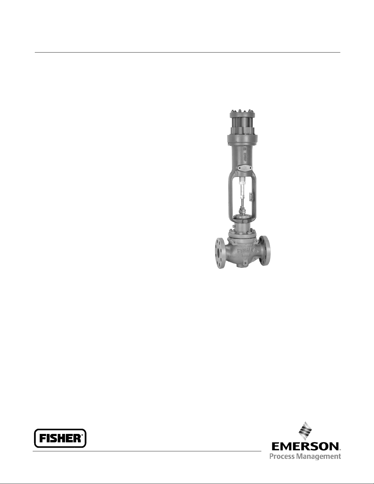
The Fisher 1B pump governor actuator (figure 1) is
used to maintain a constant discharge pressure on
steam driven turbine or reciprocating pumps and for
pressure reducing or pressure relief applications.
Typical pump governor applications include fire
pumps, boiler feedwater pumps, a nd industrial or
refining pumps where the discharge medium is oil,
steam, air, or other noncorrosive fluid.
The 1BR pump governor actuator is combined with a
push-down-to-openvalveforserviceasarelief
governor. A relief governor is used to divert excess
pump discharge to the suction side of the pump.
Features
Rugged Construction–Brass and steel construction
combats wear for long service life.
Product Bulletin
61.9:1B
December 2012
Ease of Maintenance–Few moving parts and easy
access reduce maintenance and downtime.
Ease of Adjustment–Readily accessible spring
adjustment without removing any parts.
Leakfree Service–Leakfree piston cups available to
66_C(150_F).
Fast Acting– Direct-operated configuration
provides fast speed of response.
W2232-1
Fisher 1B Actuator on Direct-Acting easy-et Valve
www.Fisher.com
Page 2
Product Bulletin
61.9:1B
December 2012
Specifications
1B Pump Governor
D100181X012
Available Configurations
1B: Direct-acting with increased control pressure
closing push-down-to-closevalvessuchasFisherED
and ET
1BR: Reverse-acting with increased control pressure
opening push-down-to-open valves such as Fisher
EDR and ETR
Maximum Cylinder Pressure
(1)
Construction Materials
Cylinder Cap and Yoke: Cast iron
Piston: Brass, chrome-plated
Cylinder: Brass
Piston Rod: Steel, zinc-plated
Piston Cup: Partial Nitrile or 100% Nitrile for leakfree
service
Maximum Cylinder Ope rating Temperature
130_C(265_F)
48.3 bar (700 psi)
Spring Ranges
See table 1
or 66_C(150_F) for leakfree service
Cylinder Connections
Seefigure2
Yoke Boss and Stem Diameters
Effective Piston Area
2
45 cm
Travel
(7.07 square inches)
Yoke Boss Stem Yoke Boss Stem
54
71
Up to 19.1 mm (0.75 inch)
APPROXIMATE WEIGHTS
Travel Stops
Available for 6 and 11.1 mm (0.25 and 0.4375 inch)
travels (reverse acting constructions)
1. The pressure/temperaturelimits in this bulletin and any applicable standard or code limitation forvalveshould not be exceeded.
Actuator with 54 mm (2-1/8 Inch) Yoke Boss: 9.1 kg
(20 pounds)
Actuator with 71 mm (2-13/16 Inch) Yoke Boss: 20.4
kg (45 pounds)
mm INCHES
9.5
12.7
2-1/8
2-13/16
(1)
3/8
1/2
Table 1. S pring Information
METRIC UNITS U.S. UNITS
TYPE NUMBER
1B
9.5 mm
(3/8 inch)
stem
1BR
2
12.7 mm
(1/2 inch)
(1)
stem
1. If the valve/stemconnection is cut down to 9.5 mm (3/8 inch),thenthe maximum relief pressure range is limited to 22.1 bar (320 psig).
Pressure
Range, Bar
6.6 to 8.3
8.3 to 13.5
13.5 to 15.9
15.9 to 22.1
22.1 to 34.5
6.6 to 8.3
8.3 to 13.5
13.5 to 15.9
15.9 to 22.1
6.6 to 8.3
8.3 to 13.5
13.5 to 15.9
15.9 to 22.1
22.1 to 34.5
Spring
Rate,
N/mm
85.8
221
257
368
928
85.8
221
257
368
85.8
221
257
368
928
Sensitivity
mm/Bar
0.524
0.204
0.175
0.122
0.048
0.524
0.204
0.175
0.122
0.524
0.204
0.175
0.122
0.048
Safe Load,NPressure
4715
8184
9786
13,545
23,575
4715
8184
9786
13,545
4715
8184
9786
13,545
23,575
Range, Psig
95 to 120
120 to 195
195 to 230
230 to 320
320 to 500
95 to 120
120 to 195
195 to 230
230 to 320
95 to 120
120 to 195
195 to 230
230 to 320
320 to 500
Spring
Rate,
Lbf/in
490
1260
1470
2100
5300
490
1260
1470
2100
490
1260
1470
2100
5300
Sensitivity
In./Psi
0.014
0.006
0.005
0.003
0.001
0.014
0.006
0.005
0.003
0.014
0.006
0.005
0.003
0.001
Safe Load,
Lbf
1060
1840
2200
3045
5300
1060
1840
2200
3045
1060
1840
2200
3045
5300
SPRING PART
NUMBER
1F176827092
1E795327082
1E792427082
1E793327082
1H106827082
1F176827092
1E795327082
1E792427082
1E793327082
1F176827092
1E795327082
1E792427082
1E793327082
1H106827082
Page 3

1B Pump Governor
D100181X012
Product Bulletin
61.9:1B
December 2012
Figure 1. Fisher 1B-ED Pump Governor Sectional
W2254-1
Push-Down-To-Open Valve
(P
A-FP-FS)
Pt= Pc-
where:
P
=forcesummation,pressure acting on piston
t
(psig)
P
= cylinder pressure (psig)
c
P
= valve inlet pressure (psig)
1
A = valve plug unbalance area (in square inches)
(from Catalog 12)
F
= packing friction force (lbf) (from Catalog 12)
p
F
= seat load force (lbf) (from Catalog 12). If tight
s
shutoff is not a service condition, F
considered to be zero
1
7.07
may be
s
Sizing Information
The following procedure is used to select the correct
spring for the actuator:
1. Determine the average steam cylinder pressure and
steam required by t he pump from the Pump Governor
Sizing bulletin (61.9:005, D100182X012).
2. DeterminethepropervalvesizefromCatalog12.
3. Find:
Push-Down-To-Close Valve
(P
A-FP+FS)
Pt= Pc-
1
7.07
4. Selectthespringfromtable1thathasthepressure
range which includes P
.IfPtis equal to the upper
t
pressure range, go to the next larger size spring.
Table 2. Dimensions
VALVE SIZE, NPS
1/2 to 1-1/2
2to4
DIMENSION H
mm Inches
548
597
21-9/16
23-1/2
Figure 2. Dimensions (also see table 2)
159
12A7093-B
A2398-2
(6-1/4)
1/2-14 NPT
CYLINDER PRESSURE CONNECTION
1/4-18 NPT
CYLINDER
VENT
CONNECTION
H
mm
(INCH)
3
Page 4

Product Bulletin
61.9:1B
December 2012
Figure 3. Typical Installations
1B PUMP
GOVERNOR
ACTUATOR
1B Pump Governor
D100181X012
NEEDLE
VALVE
PUMP
DISCHARGE
1BR PUMP
GOVERNOR ACTUATOR
STEAM
SUPPLY
AC4650-B
A2397-1
TURBINE
EXHAUST
1B ACTUATOR TO MAINTAIN
CONSTANT PUMP DISCHARGE PRESSURE
SUCTION
Installation
1B and 1BR pump governor actuators may be installed
in any position. Typical installations are shown in figure
3.Seefigure2fordimensions.
Ordering Information
Application Information
When ordering a 1B or 1BR pump governor actuator,
specify:
1. Action (direct or reverse)
2. Pressure range
PUMP
DISCHARGE
SUCTION
14A2789-A
A3515
1BR ACTUATOR TO DIVERT
EXCESS PUMP DISCHARGE PRESSURE
3. Temperature (normal operating and maximum)
4. Flow rate (normal and maximum)
5. Required spring (see Sizing Information)
Actuator Information
Refer to the specifications table. Review the
description to the right of each specification and in the
referenced table. Specify choice where there is a
selection to be made.
Valve Body and Accessories
Information
Refer to separate valve body and accessories bulletins
for ordering information.
Neither Emerson, Emerson Process Management, nor any of their affiliated entities assumes responsibility for the selection, use or maintenance
of any product. Responsibility for proper selection, use, and maintenance of any product remains solely with the purchaser and end user.
Fisher and easy-e are marks owned by one of the companies in the Emerson Process Management business unit of Emerson Electric Co. Emerson Process
Management, Emerson, and the Emerson logo are trademarks and service marks of Emerson Electric Co. All other marks are the property of their respective
owners.
The contents of this publication are presented for informationalpurposes only, and while every effort has been made to ensure their accuracy, they arenot
to be construed as warranties or guarantees, express or implied, regarding the products or services described herein or their use or applicability.All sales are
governed by our terms and conditions, which are available upon request. We reserve the right to modify or improve the designs or specifications of such
products at any time without notice.
Emerson Process Management
Marshalltown, Iowa 50158 USA
Sorocaba, 18087 Brazil
Chatham, Kent ME4 4QZ UK
Dubai, United Arab Emirates
Singapore 128461 Singapore
www.Fisher.com
E 1979, 2012 Fisher Controls InternationalLLC.Allrights reserved.
4
 Loading...