

Page 1
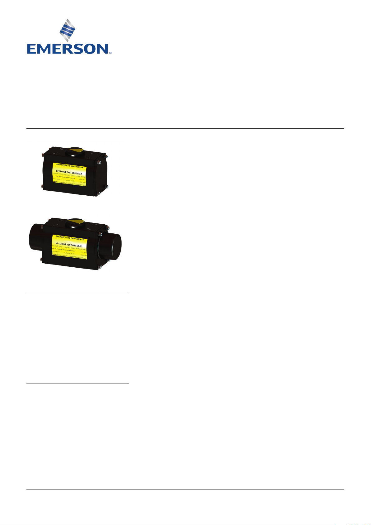
KEYSTONE FIGURE 89 PNEUMATIC ACTUATORS
INSTALLATION AND MAINTENANCE INSTRUCTIONS
Before installation these instructions must be fully read and understood
INTRODUCTION
The Keystone F89 pneumatic actuator range
isavailable in 4 mounting options:
• F89D - ISO 5211 shaft and flange Metricthreading
• F89E - Keystone shaft / ISO flange Metricthreading
• F89U - Keystone shaft and flange Metricthreading
• F89U - Keystone shaft and flange Imperialthreading
GENERAL PNEUMATIC SYSTEM
RECOMMENDATIONS
All Keystone pneumatic actuators are factory
lubricated with Castrol LMM grease, and
unless the operating environment is extremely
harsh, do not require re-lubrication.
For applications where the environmental
temperature reaches temperatures up to
-52°C (-62°F) a low temp version is used
(Cassida LTS 1).
To maintain maximum efficiency with this
actuator we advise that the following basic
system recommendations are followed:
1. For maximum cycle life the air quality of
compressed air should be 2.4.1 as per
ISO8573-1 standard.
2. Where pipelines are subjected to extremes
of temperature, the system should be fitted
with suitable air drying equipment.
3. When working at low temperatures, it is
important that the compressed air has been
dried to a dew point of less than the ambient
temperature. If this is not the case, water
will be condensed from the compressed
air and freeze causing damage to the seals
inside the actuator, which could result in
actuator failure.
4. Air control lines should be fitted in
accordance with a “Recommended Piping
Practice” and should not have loops,
whichmay trap condensate.
5. All air connection pipe ends should be
thoroughly cleaned and deburred after
cutting, to ensure that the pipeline is clear
of debris.
6. If pipelines are hydraulically tested, then
the lines should be “blown down” with
pressurized air to clear all traces of water,
prior to connecting lines to the actuator.
7. Where pipe fitting sealants are used, they
should be applied to the male threads only,
to avoid excess compound being forced into
the actuator control lines.
8. Where air filter equipment is used, the air
filters should be situated in positions that
allow easy access to maintain and/or drain.
9. Where pneumatic valve positioners or
pneumatic controllers are fitted to the valve
actuator assemblies, oil mist lubricated air
should not be used unless the manufacturer
states specifically that the controllers are
compatible with lubricated air.
NOTE
Keystone F89 actuators are rated for compressed air
pressure in the range of 2.75 barg (40 psig) to 8.3barg
(120 psig) and will withstand a maximum static
pressure of 10 barg (145 psig).
WARNING
For safety reasons, DO NOT "air assist" single
acting pneumatic actuators.
© 2017 Emerson. All Rights Reserved.Emerson.com/FinalControl VCIOM-03059-EN 20/12
Page 2
KEYSTONE FIGURE 89 PNEUMATIC ACTUATORS
INSTALLATION AND MAINTENANCE INSTRUCTIONS
CONSTRUCTION
Keystone F89 actuators are designed to be
mounted to quarter turn valves either directly
or using the correct mounting brackets/adapter
and sizing products.
All models are of the opposed piston type.
Eachpiston incorporates an integral rack
which engages with a one piece pinion drive
shaft. Thedrive shaft is Zinc+Nickel plated
for maximum protection. The actuator body
is of extruded aluminium, and fitted with
“engineered polymer” bearings at the drive
shaft locations. Bearing and piston seals are
dynamic “O-ring” type. The actuator drive is by
means of a double keyed female shaft output
(F89E/U) or female double square (star; F89D)
conforming to EN ISO 5211.
A comprehensive range of adaptors is available
for fitting the actuator shaft to the valve shaft.
The top of the actuator shaft has a female
DD16x11 connection for direct mounting of
theAVID accessories, or can be fitted with
an insert to be compliant with the Namur
standard.
Adjustable travel stops are provided for each
end of travel to ensure that the actuator will
open and close the valve precisely.
STORAGE
All actuators leave the factory tested and
in excellent working condition and finish.
Inorder to maintain these characteristics
until the actuator is installed in the plant, it is
necessary to observe the following rules and
take appropriate measures during the storage
period.
STANDARD INSTALLATION
The F89 actuator can be used for butterfly
valves, ball valves and all quarter turn devices,
in double acting or spring return configuration.
Single acting actuators are supplied
as FAIL-CLOSE (CW) as standard.
Reverseacting (FAIL-OPEN; CCW) must be
specified
at the time of order. Alternatively
it is possible to change an actuator from
FAIL-CLOSE
to FAIL-OPEN by a trained
and certified mechanical engineer using
the assembly/disassembly instructions as
described in this document.
These installation instructions assume that
the actuator is installed with the cylinder axis
parallel to the axis of the valve bore (in line).
Please ensure that you have an actuator
with the correct drive, and that the valve and
actuator are in the following positions:
1a. Double acting units and spring return
units in FAIL-CLOSE position: valve closed,
actuator fully clockwise.
1b. Double acting units and spring return units
in FAIL-OPEN position: valve open, actuator
fully counterclockwise.
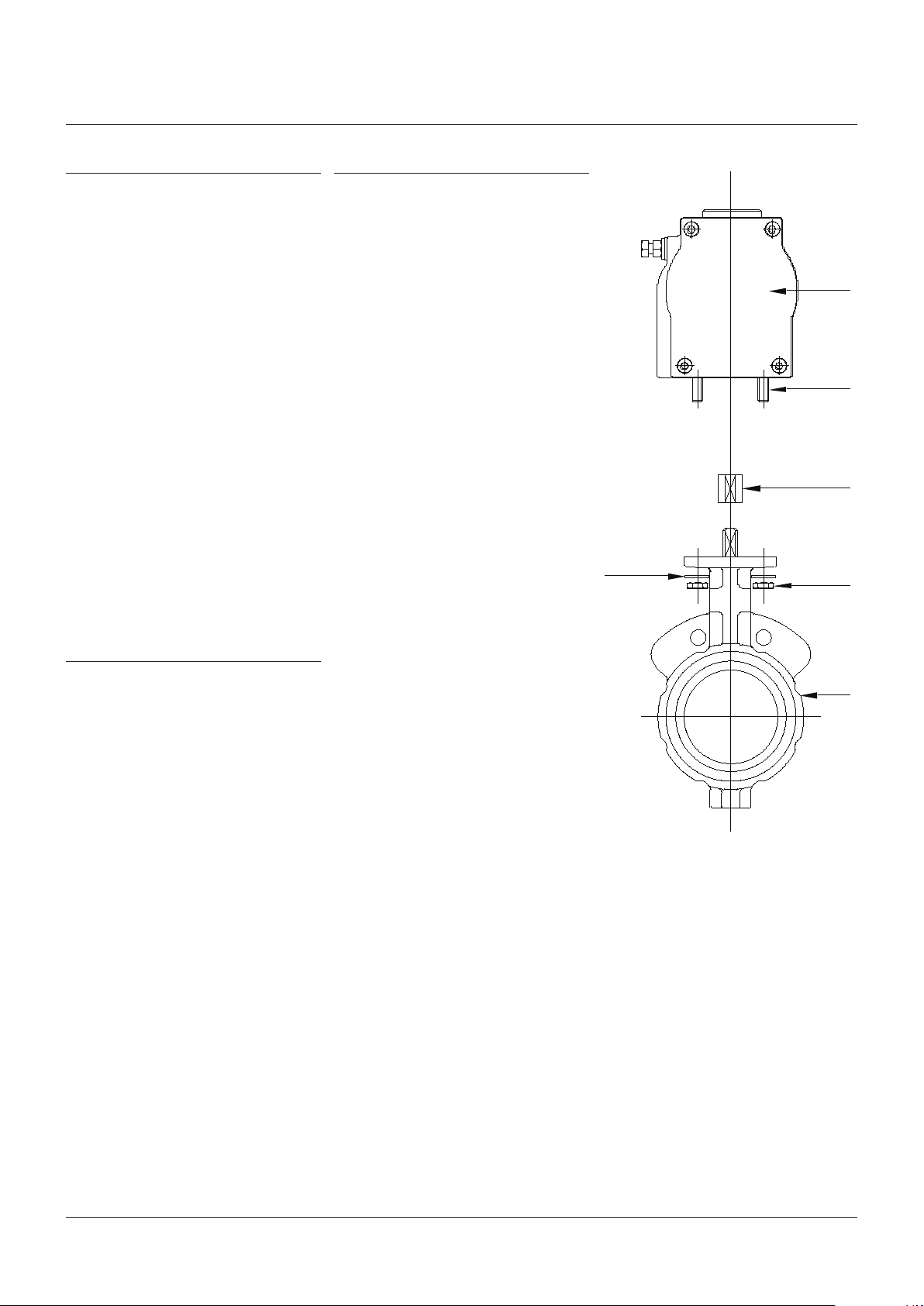
Butterfly valve application
Mounting to resilient seated butterfly valves
(withEN ISO 5211 or Keystone mounting)
2a. Screw the actuator mounting studs tightly
into the actuator base.
3a. Install the correct shaft adapter if required.
4a. Mount the actuator onto the valve top
flange and secure using a lockwasher and
nut on each mounting stud.
Lockwasher
Actuator mounting - BFV
KEYSTONE
Pneumatic
actuator
Stud
Adaptor
ifrequired
Nut
Valve
1. Make sure that the transport plugs remain
fitted in the air connections. These plastic
plugs close the air inlets, but do not have a
waterproof function, as they are a means
of protection against the entry of foreign
matter during transport.
For long term and specifically outdoor
storage these plastic plugs need to be
replaced with plugs providing a complete
weatherproof protection.
2. If the actuators are supplied separately
from the valves, they must be placed onto a
wooden pallet in order to prevent damaging
the valve coupling. For long term outdoor
storage it is advised to coat the coupling
parts with protective oil or grease.
3. In case of long term storage, it is advised
to keep the actuators in a dry place or to
provide some means of weather protection.
FIGURE 1
2
Page 3
KEYSTONE FIGURE 89 PNEUMATIC ACTUATORS
INSTALLATION AND MAINTENANCE INSTRUCTIONS
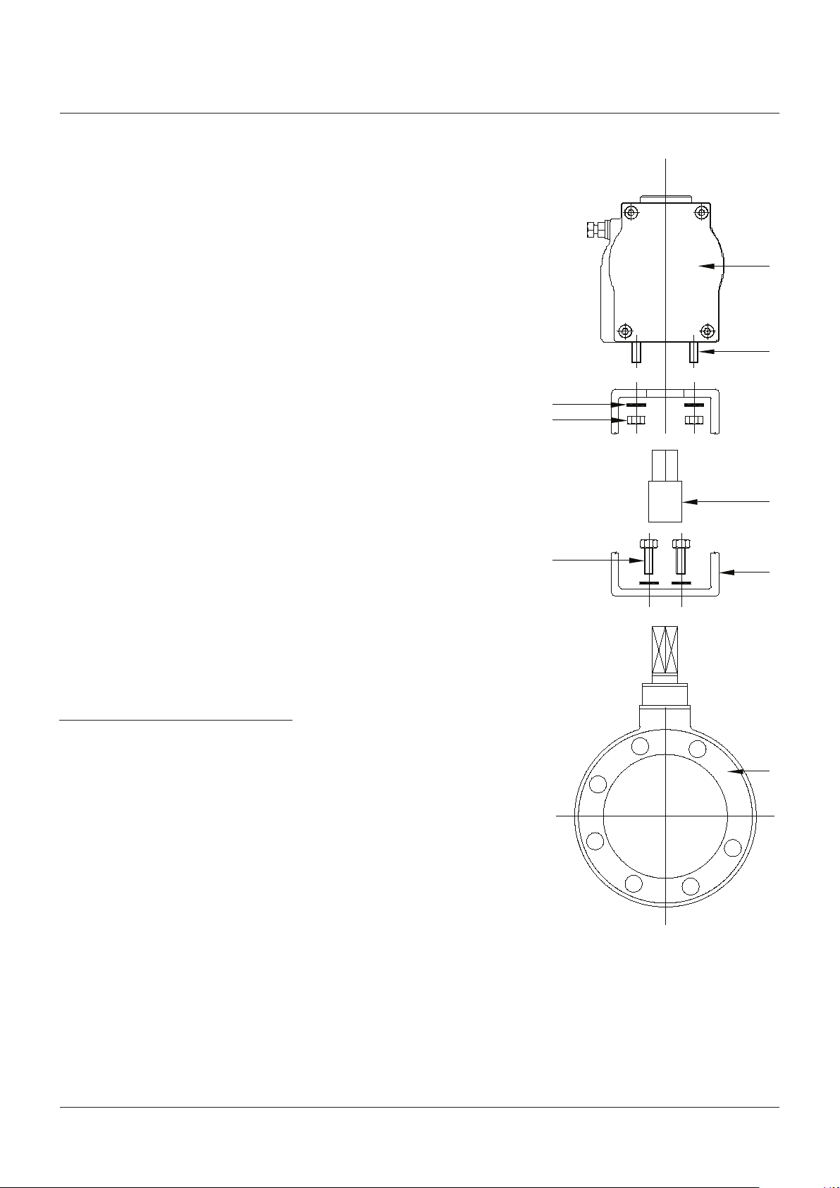
Ball valve application
Mounting to ball and high performance butterfly
valves using a bracket
2b. Screw the actuator mounting studs
tightly into the actuator base and secure
themounting bracket to the underside of
the actuator using four nuts and washers
as shown in Figure 1.
3b. Install the appropriate coupling onto the
valve stem. The coupling should be lightly
tapped or pressed onto the valve stem.
Theuse of a lubricant is recommended.
4b. Mount the actuator and bracket onto the
valve top flange using the appropriate bolts.
All quarter turn valve types
5. Before installing the valve/actuator
assembly in a piping system, the disc travel
should be verified and adjusted if necessary
using the travel stop screws (see detailed
instructions for travel setting).
6. When installing the valve/actuator
assembly into the pipeline, ensure that
thespecific instructions relating to
thevalve installation are followed.
NOTE
Some valves may require to be fitted into the pipeline
prior to mounting the actuator. Rubber lined butterfly
valves are an example of this.
Lockwasher
Nut
Bolt
Actuator mounting - BV
Pneumatic
actuator
Stud
Coupling
ifrequired
Bracket
ifrequired
7. For valves which need to be installed in
thepipeline prior to fitting the actuator,
ensure that the valve is operated into
its failsafe position before mounting
theactuator onto the valve.
NON-STANDARD INSTALLATION - DOUBLE
ACTING AND SPRING RETURN ACTUATORS
In circumstances where the actuator is required
to be installed in the transverse position i.e.
at right angles to the valve bore (across line),
theactuator must be rotated through 90°.
Thisis achieved in the following manner.
All quarter turn valve types
1. Remove the actuator from the valve or the
bracket by removing the 4 fixing bolts/nuts,
and withdraw it vertically from the valve.
2. Reposition the shaft insert 90 degrees for
Double-D connections. Bored-keyed and
star drives do not require this action.
3. Rotate the actuator 90 degrees.
4. Refit the actuator to the top of the valve or
to the bracket. Pay attention to the output
drive of the actuator to be in line with
thevalve shaft and/or shaft insert.
FIGURE 2
Ball
valve
3
Page 4
KEYSTONE FIGURE 89 PNEUMATIC ACTUATORS
INSTALLATION AND MAINTENANCE INSTRUCTIONS
22 15 20
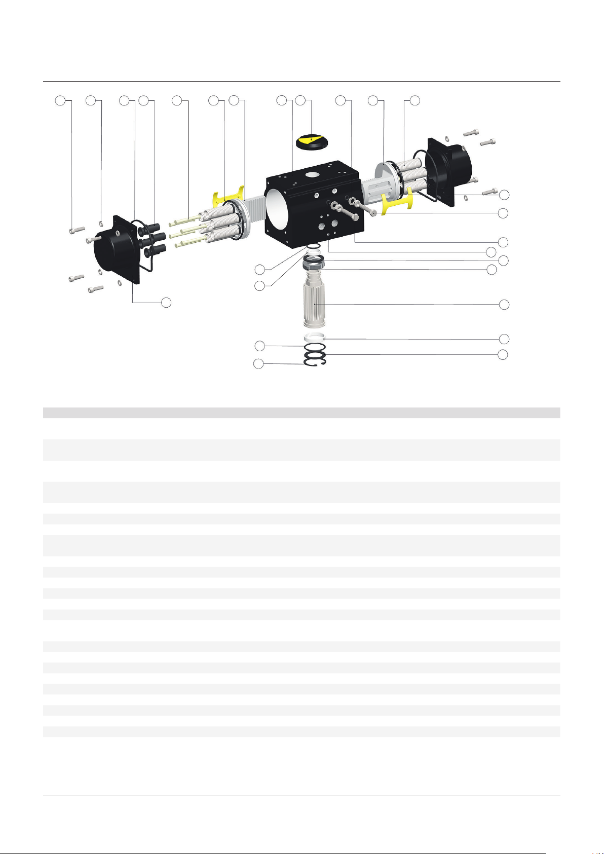
FIGURE 3
8 7
4
9 3
1 25 14 3 6
16
10
17
24
18
21
23
19
12
5
2
11
13
TABLE 1 MATERIALS OF CONSTRUCTION
No. Item Material US material std BS material std DIN material std Finish
1 Body Extruded aluminium
ASTM B221 type 6063T6
2 Pinion Hot rolled carbon steel bar ASTM
A108 grade 1045
3 Piston Die cast aluminium alloy ASTM B85
type A380 /BS 1490 grade LM24
4 End cap Die cast aluminium alloy ASTM B85
type A380/BS 1490 grade LM24
5 Cam Cast grade SAE 1045/C45 / EN8 Blackodised
6 Spring Spring steel as per ASTM A401 ASTM A401 BS 5216 HS3 DIN 17223 Pti Epoxy coated 30-40 microns
7 Spring retainer Carbon steel Zinc plated
8 Spring cup Die cast aluminium alloy ASTM B85
type A380 /BS 1490 grade LM24
9 Piston guide Zytel 101F NC010 Natural
(1)
10 Top bearing PAR
11 Bottom bearing PAR
12 Top thrust washer POM
13 Bottom thrust washer POM
14 Travel stop washer SS
15 End cap washer
+ 25% glass filled Natural
(1)
+ 25% glass filled Natural
(2)
(2)
(3)
ISO 3506 A2-70 grade Natural
(3)
SS
ISO 3506 A2-70 grade Natural
(spring washer)
16 Top O-ring (pinion) NBR shore 70 A Natural
17 Bottom O-ring (pinion) NBR shore 70 A Natural
18 O-ring (piston) NBR shore 70 A Natural
19 O-ring (travel stop) NBR shore 70 A Natural
20 Gasket (end cap) NBR shore 70 A Natural
(3)
21 Bolt - travel stop SS
22 Bolt - end cap SS
23 Nut - travel stop SS
ISO 3506 A2-70 grade Natural
(3)
ISO 3506 A2-70 grade Natural
(3)
ISO 3506 A2-70 grade Natural
24 Circlip (bottom) Mild steel Natural
25 Position indicator ABS plastic Natural
ASTM B221 BS 1474 6063 DIN 3.33206.51 Anodized 15-25 microns +
ESPC 80-120 microns
A108 BS 970 080M40 C40 Electroless nickel plated
10-15 microns
ASTM B85 BS 1490 DIN 1725-2300 or 226 Anodized
ASTM B85 BS 1490 DIN 1725-2300 or 226 ESPC 80-120 microns
ASTM B85 BS 1490 DIN1725-2300 or 226 Anodized
Natural
Natural
1. POM Acetal Resin 2. Polyoxymethylene 3. Stainless steel
4
Page 5

KEYSTONE FIGURE 89 PNEUMATIC ACTUATORS
INSTALLATION AND MAINTENANCE INSTRUCTIONS
DISASSEMBLY PROCEDURE - DOUBLE
ACTING ACTUATORS
WARNING
Remove air pressure and observe normal safety
precautions, including the use of eye protection.
1. Pull of the indicator cap (25) from the top
of the actuator. If this cap is too tight, light
pressure may be applied to the underside
via a short length of round bar inserted from
the bottom end of the actuator shaft.
Note: levering with a screwdriver is
considered to be a potentially dangerous
practice and should be avoided.
2. Remove both travel stop bolts (21),
afterslackening the lock nuts.
3. Verify that the end caps are for double
acting actuator (flat), and loosen end cap
fixing screws evenly (22).
4. Remove end caps (4).
5. Using a suitable wrench in the top of
thepinion shaft (2), turn the shaft counter
clockwise to drive the pistons apart.
Removethe pistons (3) complete with
backing pads/O-rings, etc.
6. Remove circlip (24) from the bottom bore of
the actuator including thrust washer (13).
7. Protect the actuator bore during pinion
disassembly, and tap shaft downward.
Thetravel stop cam (5) is firmly attached to
the pinion and needs to be released before
removing the pinion from the actuator body.
8. Remove the pinion, but take care to protect
the actuator bore.
9. Remove top and bottom O-rings (16 and 17)
from the pinion shaft.
10. Remove top and bottom bearings (10 and 11)
from the pinion shaft.
WARNING
If after loosening the screws by 5 mm there is
still compression on the spring pack re-tighten
theend cap screws and return the unit to the
factory for service.
4. Remove end caps (4) and spring packs.
Inorder to avoid the springs falling out place
the actuator with the end cap on top.
WARNING
Do not disassemble the pre-compressed spring
packs, as the springs are under high force.
5. Using a suitable wrench in the top of the
pinion shaft (2), turn the shaft counter
clockwise to drive the pistons apart.
Removethe pistons (3) complete with
backing pads/O-rings, etc.
6. Remove circlip (24) from the bottom bore of
the actuator including thrust washer (13).
7. Protect the actuator bore during pinion
disassembly, and tap shaft downward.
Thetravel stop cam (5) is firmly attached to
the pinion and needs to be released before
removing the pinion from the actuator body.
8. Remove the pinion, but take care to protect
the actuator bore.
9. Remove top and bottom O-rings (16 and 17)
from the pinion shaft.
10. Remove top and bottom bearings (10 and 11)
from the pinion shaft.
DISASSEMBLY PROCEDURE - SINGLE ACTING
ACTUATORS
WARNING
Remove air pressure and observe normal safety
precautions, including the use of eye protection.
Always ensure that spring return actuators
are in fail safe position before attempting any
maintenance. Pay particular attention to this
requirement when manual operators are fitted.
1. Pull of the indicator cap (25) from the top
of the actuator. If this cap is too tight, light
pressure may be applied to the underside
via a short length of round bar inserted
from the bottom end of the actuatorshaft.
Note:levering with a screwdriver is
considered to be a potentially dangerous
practice and should be avoided.
2. Remove both travel stop bolts (21),
afterslackening the lock nuts.
3. Loosen end cap fixing screws evenly (22)
until the spring load is relaxed (3-5 mm).
5
Page 6

KEYSTONE FIGURE 89 PNEUMATIC ACTUATORS
INSTALLATION AND MAINTENANCE INSTRUCTIONS
ASSEMBLY PROCEDURE - DOUBLE ACTING
ACTUATORS
1. Clean all disassembled items and replace
all items as O-rings, bearings, and backing
pads as provided in the soft good kit.
2. Liberally grease the body bore with
thegrease specified.
3. Coat all O-rings and seals with the grease
specified.
4. Output shaft assembly:
a. Fit the top bearing assembly (10) on
thetop of the pinion shaft (2) with the top
O-ring (16) uppermost.
b. Fit the bottom bearing assembly (11) on
to the bottom of the pinion shaft with
thebottom O-ring (17) at the bottom.
c. Fit the top thrust washer (12).
5. Carefully insert pinion shaft assembly from
underside of the actuator.
6. While inserting, fit the travel stop cam
(5) on top of the pinion shaft from within
theactuator bore and monitor the position
of the key in the shaft and the travel stop
cam as shown in figure 4. Finish with a firm
push to ensure full location.
7. Fit bottom thrust washer (13) and internal
circlip (25) to bottom recess of body to
locate the shaft assembly.
8. Fit the O-ring seals (18) on the pistons (3),
and grease the rack.
9.
Orientate the output shaft at 45° as in figure 4.
10. Insert pistons completely with backing
pads (9) with piston legs on left hand side of
thebore when viewed from the O-ring end
of the piston (figure 4), until racks engages
with the pinion and then push gently inward.
Theactuator is now in the fully closed
position, and the shaft indication should be
at -5 degrees (pointing slightly to the right).
11. Turn the pinion shaft counterclockwise until
it is orientated in line with the major axis of
the actuator body. The shaft is now in the
closed position.
12. Insert the right (close) travel stop bolt (21)
together with the O-ring (19), washer (14)
and lock nut (23) until the bolt hits the travel
stop cam. Tighten the lock nut.
13. Turn the shaft counterclockwise through
90° to bring it in line with the center line of
the actuator bore. The actuator is now in
theopen position.
14. Insert the left (open) travel stop bolt (21)
together with the O-ring (19), washer (14)
and lock nut (23) until the bolt hits the
travel stop cam. Tighten the lock nut.
Thepositionof the travel stop bolts need
to be verified after valve assembly and
adjusted if required.
15. Fit end cap gaskets (20) to the end caps (4)
using a light smear of grease.
16. Fit double acting end caps (flat model) to
body evenly and tighten the end cap screws
with the recommended torque (table 2).
17. Fit position indicator to top of the actuator.
18. Operate the actuator to open and close
positions using compressed air and note
the actual positions. Adjust the travel stops
if required following the routine described
in this document. If the required travel is
not achieved, refer to the trouble shooting
guide.
Standard direction of rotation
Piston guide
Stopper bolt
FIGURE 4 (top view)
Cam
Pinion Body
Direction of movement
Piston
O-ring
Gear mark
indication
6
Page 7

KEYSTONE FIGURE 89 PNEUMATIC ACTUATORS
INSTALLATION AND MAINTENANCE INSTRUCTIONS
ASSEMBLY PROCEDURE - SPRING RETURN
ACTUATORS
(FAIL-CLOSE - clockwise to close)
1. Follow the steps 1 to 14 of the double acting
assembly procedure.
2. For spring return actuators the following
additional actions are required:
a. Turn the pinion (2) clockwise to the close
position.
b. Position the actuator vertically with
thepiston top in a horizontal plane
(makesure that the lower part is placed
on a clean surface).
c.
Locate the correct number of spring
packs (6) in the cavities on the piston head.
Fordurability make sure to divide the
number of springs evenly on both sides,
with a maximum difference of 1 spring,
and use the configuration as indicated in
figure 6 based on thenumber of springs.
d. Fit the first end cap as described in
thefollowing description and repeat
thesequence for the other side.
3. Fit end cap gaskets (20) to the end caps (4)
usingalight smear of grease.
4. Place end cap on top of the spring packs
and make sure that the springs are located
in the spring pockets (cavities). Fit end cap
to body evenly using end cap screws (
22)
and washer (15). Tighten the end capscrews
with the recommended torque (table 2).
Makesure that the springs remain in
position during assembly of the end cap.
5. Fit position indicator (25) to top of
theactuator.
6.
Operate the actuator to open and close
positions using compressed air and note
theactual positions. Adjust the travel stops
if required following the routine described in
this document. If the required travel is not
achieved, refer to the trouble shooting guide.
ASSEMBLY PROCEDURE - SPRING RETURN
ACTUATORS
(FAIL-OPEN - counterclockwise to open)
1. Follow the steps 1 to 8 of the double acting
assembly procedure.
2.
Orientate the output shaft at 45° as in figure 5.
3. Insert pistons completely with backing pads
(9) with piston legs on right hand side of
the bore when viewed from the O-ring end
of the piston (figure 5), until racks engages
with the pinion and then push gently
inward. Theactuator is now in the fully open
position, and the shaft indication should be
at 95 degrees.
4. Turn the pinion shaft clockwise until it is
orientated in line with the center line of
theactuator bore (90° position). The shaft is
now in the open position.
5. Insert the left (open) travel stop bolt (21)
together with the O-ring (19), washers (14)
and lock nut (23) until the bolt hits the travel
stop cam. Tighten the lock nut.
6. Turn the shaft clockwise to 0° to bring it in
line with the major axis of the actuator body.
The actuator is now in the close position.
7.
Insert the right (close) travel stop bolt (21)
together with the O-ring (19), washer (14) and
lock nut (23) until the bolt hits the travel stop
cam. Tighten the lock nut. The position of
the travel stop bolts need to be verified after
valve assembly and adjusted if required.
8. For spring return actuators the following
additional actions are required:
a. Turn the pinion counterclockwise to
theopen position.
b. Position the actuator vertically with
the piston top in a horizontal plane
(makesure that the lower part is placed
on a clean surface).
c. Locate the correct number of springs
in the cavities on the piston head.
Usetheconfiguration as indicated
in figure 6 based on the number of
springs. For durability make sure to
divide thenumber of springs evenly on
both sides, with a maximum difference
of1spring.
d. Fit the first end cap as described in
thefollowing description and repeat
thesequence for the other side.
9. Fit end gap gaskets (20) to the end caps (4)
using alight smear of grease.
10. Place end cap on top of the spring packs,
and fit end cap to body evenly using end cap
screws (22) and washer (15). Tighten the end
cap screws with the recommended torque
table. Make sure that the springs remain in
position during assembly of the end cap.
11. Fit position indicator (25) to top
oftheactuator.
12. Operate the actuator to open and close
positions using compressed air and note
the actual positions. Adjust the travel stops
if required following the routine described
in this document. If the required travel is
not achieved, refer to the trouble shooting
guide.
Non-standard direction of rotation
Piston
Direction of
FIGURE 5 (top view)
movement
Pinion
Cam
Body Piston guide O-ring
Stopper bolt
Gear mark
indication
7
Page 8

KEYSTONE FIGURE 89 PNEUMATIC ACTUATORS
INSTALLATION AND MAINTENANCE INSTRUCTIONS
SPRING ALLOCATION
In spring return applications the number of
springs used determine the torque provided for
fail safe applications. For optimal performance
the number of springs used is based on
thevalve type used using the F89 actuator
torque table (normaly closed applications):
- Ball valves: use spring torque level which
matches the spring torque at 90 degrees with
the supplied air starting torque at 0 degrees.
- Butterfly valves: use spring torque level which
matches the spring torque at 0 degrees with
the supplied air torque at 0 degrees.
The number of springs used can vary between
4 and 12 pieces. For durability make sure to
divide the number of springs evenly on both
sides, with a maximum difference of 1 spring,
and use the configuration as indicated in
figure6 based on the number of springs.
Left
Right
4 springs
5 springs
6 springs
7 springs
8 springs
FIGURE 6 - Spring allocation
9 springs
10 springs
11 springs
12 springs
8
Page 9

KEYSTONE FIGURE 89 PNEUMATIC ACTUATORS
INSTALLATION AND MAINTENANCE INSTRUCTIONS
SETTING OF INTERNAL TRAVEL STOPS
The Keystone F89 is fitted with integral travel
stops to enable setting of exact travel for the
valve being operated. These stops allow over and
under travel adjustment of ± 5° on each end.
WARNING
• Under no circumstances the travel stop bolts
should be completely withdrawn from the
actuator while compressed air is being applied.
• Travel stop bolts should not be used for manual
override actions.
• After setting the travel stops, accessories
mounted to the top of the actuator must be
re-adjusted accordingly.
To set the travel stops - double acting actuator
1. Operate the valve/actuator assembly to
theclosed position.
2. Remove air supply.
3. Slacken locknut on the close travel stop
(right).
4. Turn the travel stop clockwise to reduce
travel or counterclockwise to increase
travel.
5. Re-tighten locknut.
6. Reconnect air supply and check that
theclose position is correct. If not repeat
from instruction 2.
7. Apply air to the open position.
8. Remove air supply.
9. Adjust open travel stop bolt (left) as per
instruction 3 to 6 above.
To set the travel stops - spring return
actuator FAIL-CLOSE
1. Remove air supply and check actual
closeposition.
2. Apply air to operate the actuator to the
openposition.
3. Whilst the air supply is maintained, slacken
locknut on the close travel stop (right)
as the close position is now able to be
adjusted.
4. Turn the travel stop clockwise to reduce
travel or counterclockwise to increase
travel.
5. Re-tighten locknut
6. Remove air supply to close the actuator.
Ifcorrect close position is not achieved
repeat from instruction 2.
7. Apply air to drive the actuator to the open
position and check actual open position.
8. Remove air supply so that actuator closes,
and the open travel stop bolt (left) can
beadjusted.
9. Adjust open travel stop bolt as per
instruction above.
10. Re-tighten lock nut.
11. Apply air and check open position.
Ifcorrectopen position is not achieved,
repeat from instruction 7.
Cam adjustment (standard direction of rotation)
Cam
Pinion
O-ring
Actuator body
Plain washer
Spring washer
Locking nut
Piston close adjustment bolt
Cam
Pinion
O-ring
FIGURE 7 - Travel stop adjustment double acting and spring return FAIL-CLOSE
Actuator body
Plain washer
Spring washer
Locking nut
Piston open adjustment bolt
9
Page 10

KEYSTONE FIGURE 89 PNEUMATIC ACTUATORS
INSTALLATION AND MAINTENANCE INSTRUCTIONS
To set the travel stops - spring return
actuator FAIL-OPEN
1. Remove air supply and check actual
openposition.
2. Apply air to operate the actuator to the close
position.
3. Whilst the air supply is maintained, slacken
locknut on the open travel stop (left) as
theopen position is now able to be adjusted.
4. Turn the travel stop clockwise to reduce
travel or counterclockwise to increase
travel.
5. Re-tighten locknut.
6. Remove air supply to open the valve.
Ifcorrect open position is not achieved
repeat from instruction 2.
7. Apply air to operate the actuator to the close
position and check actual close position.
8. Remove air supply so that actuator opens,
and the close travel stop bolt (right) can
beadjusted.
9. Adjust close travel stop bolt as per
instruction above.
10. Re-tighten lock nut.
11. Apply air and check open position.
Ifcorrectclose position is not achieved,
repeat from instruction 7.
Cam adjustment (non-standard direction of rotation)
Cam
Pinion
O-ring
Piston open adjustment bolt
Actuator body
Plain washer
Spring washer
Locking nut
FIGURE 8 - Travel stop adjustment spring return FAIL-OPEN
Cam
Pinion
O-ring
Actuator body
Plain washer
Spring washer
Locking nut
Piston close adjustment bolt
10
Page 11

KEYSTONE FIGURE 89 PNEUMATIC ACTUATORS
INSTALLATION AND MAINTENANCE INSTRUCTIONS
MAINTENANCE
Under normal operating conditions and
when basic pneumatic system maintenance
procedures are applied, the F89 actuator will
require minimum maintenance for hundred
thousands of cycles.
If O-rings wear out and air leakage occurs,
a soft goods kit can be ordered. Please use
the (dis)assembly routines as described in
this document. Carefully inspect all other
components for wear and replace if required.
TROUBLE SHOOTING
If the actuator fails to operate the valve
correctly, carry out the following checks:
1. Check that the air supply is at the required
pressure.
2. Ensure that the air supply is not restricted in
any way.
3. Check for air leakage on supply lines to
theactuator
4. Check for air leakage at the top and bottom
of the pinion shaft.
5. Check for air leakage across the piston
seals by applying pressure to port 4 (B) and
looking for leakage from port 2 (A) and/or
reverse.
6.
Check that the valve torque has not increased
due to problems with the valve itself.
NOTE 1
Refer to disassembly and assembly procedures
forgaining access to O-rings and actuator internals
ifrequired.
NOTE 2
Reduced stroke i.e. valve not traveling the required
stroke or “backlash” may be caused by an incorrect fit
between output bore and valve stem.
PNEUMATIC AIR CONNECTION
The Series 89 actuator has 2 pcs ¼” BSP or
NPT air connections which can be used for tube
connection. Alternatively it is possible to mount
a Namur solenoid valve directly.
Comments
1. As standard, applying air to port 2 (A)
will cause the actuator to rotate in a
counterclockwise (CCW) direction to open
the valve.
2. For double acting applications, applying air
to port 4 (B) will cause the actuator to rotate
in a clockwise direction to close the valve.
3. Single acting (also called spring return)
actuators should not be “air assisted” as
this will apply excessive load to the valve
stem and cause damage.
BOLT TORQUE VALUES
As the end caps are pressurized during normal
operation, it’s important to fix them correctly
and not damage the threading due to excessive
torque. Please use the torque values as
indicated in table 2.
TABLE 2 - END CAP BOLTS TIGHTENING TORQUE
Actuator size Bolt size Tightening torque (Nm) Tightening torque (lbin)
002 M5 3 27
003 M5 3 27
004 M5 3 27
006 M5 3 27
009 M6 9 80
014 M8 15 133
020 M8 15 133
032 M10 28 248
052 M12 40 354
085 M12 40 354
140 M16 110 974
240 M16 110 974
© 2015, 2020 Emerson Electric Co. All rights reserved 12/20. Keystone is a mark owned by one of the companies in the Emerson Automation Solutions business unit of
Emerson Electric Co. The Emerson logo is a trademark and service mark of Emerson Electric Co. All other marks are the property of their prospective owners.
The contents of this publication are presented for informational purposes only, and while every effort has been made to ensure their accuracy, they are not to be
construed as warranties or guarantees, express or implied, regarding the products or services described herein or their use or applicability. All sales are governed by
our terms and conditions, which are available upon request. We reserve the right to modify or improve the designs or specifications of such products at any time without
notice.
Emerson Electric Co. does not assume responsibility for the selection, use or maintenance of any product. Responsibility for proper selection, use and maintenance of
any Emerson Electric Co. product remains solely with the purchaser.
Emerson.com/FinalControl
11
 Loading...