

Emerson ACF552ORB00, ACF552WW00 Owner's Manual
READ AND SAVE THESE INSTRUCTIONS
Part No. F40BP74610000 Form No. BP7461
Model No.: ACF552
132 cm (52”) Ceiling Fan
Owner's Manual
ACF552ORB00
ACF552WW00
Models
Net Weight: 9.8 Kg.
MOST IMPORTANT: READ THESE INSTRUCTIONS
THE FAN MUST BE INSTALLED BY A LICENSED ELECTRICIAN.
(The warranty on this fan will be void if the appliance
is not installed by a licensed electrician).
This ceiling fan is imported by MyFan as an agent for the USA design owners’ and can provide
after sales service for this product if required. Contact can be made by phone, fax or email
during normal trading hours. Copies of owner’s manuals for each model can be found on our
web site.
Phone: 1300 469 326
info@myfan.com.au
www.myfan.com.au
VERANDAH
™

2
Model No.: ACF552
WARNING To avoid fire, shock, and serious personal injury, follow these instructions.
Safety Instructions
1. Read your owner’s manual carefully and keep it for future reference.
2. Before servicing or cleaning unit, switch power off at fuse box and lock to prevent power from being switched
on accidentally. When the fuse box cannot be locked, securely fasten a warning device, such as a tag, to the
fuse box.
3. Be careful of the fan and blades when cleaning, painting, or working near the fan. Always turn off the power to
the ceiling fan before servicing.
4. Do not put anything into the fan blades while they are turning.
5. Do not operate reversing switch until fan blades have come to a complete stop.
Additional Safety Instructions for Installation
1. To avoid possible shock, be sure electricity is turned off at the fuse box before wiring, and do not operate fan
without blades.
2. All wiring must be in accordance with AS/NZS 3000 “The Wiring Rules”. The ceiling fan must be grounded as a
precaution against possible electrical shock. Electrical installation should be made or approved by a licensed
electrician.
3. The ceiling fan hanger bracket must be securely mounted and capable of reliably supporting at least 40kg.
4. The downrod furnished with the fan provides the minimum recommended floor to fan blade clearance for a
2.4 m ceiling.
5. The fan must be mounted with the fan blades at least 2.1 meters from the floor to prevent accidental contact
with the fan blades.
6. This appliance is not intended for use by persons (including children) with reduced physical, sensory or mental
capabilities, or lack of experience and knowledge, unless they have been given supervision or instruction
concerning use of the appliance by a person responsible for their safety.
NOTE: This fan is not suitable for use with solid-state speed controls.
WARNING: This product is designed to use only those parts supplied with this product and/or any accessories
designated specifically for use with this product by My Fan Pty Ltd. Substitution of parts or accessories not
designated for use with this product by My Fan Pty Ltd. could result in personal injury or property damage.
WARNING: To reduce the risk of personal injury, do not bend the blade flange when installing the blade flanges,
balancing the blades or cleaning the fan. Do not insert foreign objects in between rotating fan blades.
WARNING: This product is suitable for use in wet locations when installed with approved protection on electrical
circuits.
WARNING: This fan MUST be installed with an easily accessible isolating device to disconnect all poles of the
fan from the main supply.
WARNING
DIY
MUST BE INSTALLED
BY A LICENSED
ELECTRICIAN
3
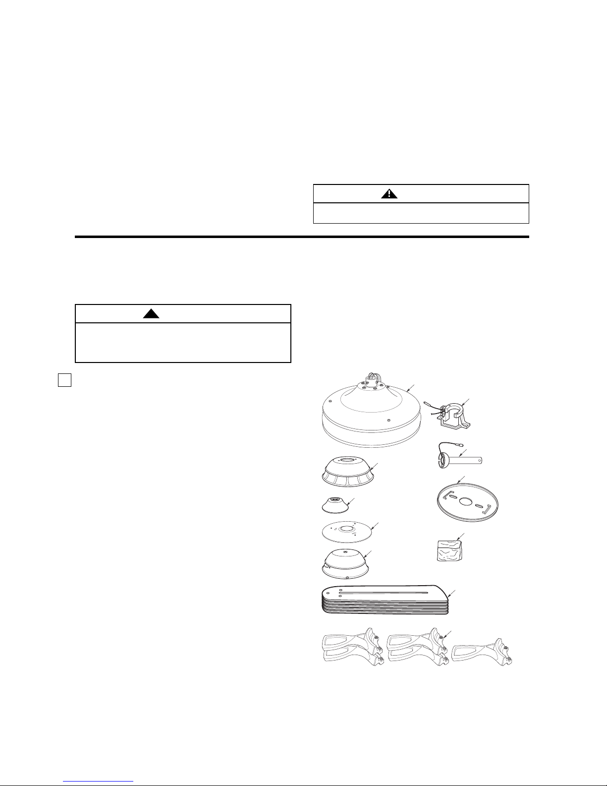
1. Unpack the items carefully to avoid damage to any
of the components.
Check to see that you have received the following
parts:
NOTE: If you are uncertain of part description,
refer to the exploded view illustration.
a. Fan motor assembly
b. One ceiling cover
c. One coupling cover
d. One switch cup cover
e. One switch cup
f. Five fan blades
g. Five fan blade holders / flanges
h. One hanger bracket
i. One hanger ball/downrod assembly
j. One canopy seal pad
k. One loose parts bag, containing:
1. One clevis pin
2. One hairpin clip
3. Sixteen M5 x 6mm washer head blade
screws
4. Two #8-32 x 1-1/4" threaded studs
5. Two #8 external tooth lockwashers
6. Two #8-32 knurled knobs
7. One M6x14mm pan head screw with
lockwasher (spare)
8. One M4x12mm flat head screw (spare)
9. One M4x10 serrated pan head screw
(spare)
10. One balancing kit
Model No.: ACF552
Tools N eeded for As sembly
One Phillips head screwdriver
One stepladder
One small blade screwdriver
One wire stripper
The fan must be installed by a licensed electrician.
WARNING
THIS FAN IS SUITABLE FOR WET LOCATIONS SUCH AS PORCHES, PATIOS, AND DECKS.
USE ONLY WITH LIGHT KITS MARKED SUITABLE FOR USE IN WET LOCATIONS.
Unpacking Instructions
For your convenience, check-off boxes are provided next to each step. As each step is completed, place a
check mark in the box. This will insure that all steps have been completed and will be helpful in finding
your place should you be interrupted.
Do not install or use fan if any part is damaged or
missing, call:
1300 469 326
WARNING
!
NOTE: Intermixing blades between fans can
cause excessive wobble. Keep blades in original
sets of five.
MATERIALS
Wiring and connectors must be of type required by
local regulations. The minimum wire would be a
3-conductor (2-wire with ground).
This manual is designed to make it as easy as possible for your Electrician to assemble and install
your ceiling fan.
a. Fan Motor Assembly
b. Ceiling Cover
c. Coupling Cover
d. Switch Cup Cover
e. Switch Cup
f. Fan Blades
g. Fan Blade Holders/Flanges
h. Hanger Bracket
i. Hanger Ball/Downrod
Assembly
j. Canopy Seal Pad
k. Loose Parts Bag

4
Model No.: ACF552
How to Put This Ceiling Fan Together
1. Remove the hanger ball by loosening the setscrew
in the hanger ball until the ball falls freely down the
downrod (Figure 1). Remove the pin from the
downrod, then remove the hanger ball. Retain the
pin and hanger ball for reinstallation in Step 6.
2. Separate, untwist and unkink the four 2 m. (80”)
motor leads/connector. Route the motor lead
wires/connector through the downrod.
3. Remove the setscrew from the motor coupling.
Insert the downrod into the motor coupling. Align
the clevis pin holes in the downrod with the holes in
the motor coupling. Install the clevis pin and secure
with the hairpin clip (Figure 2). The clevis pin must
go through the holes in the motor coupling and the
holes in the downrod. Be sure to push the straight
leg of the hairpin clip through the hole near the end
of the clevis pin until the curved portion of the
hairpin clip snaps around the clevis pin. The hairpin
clip must be properly installed to prevent the clevis
pin from working loose. Pull on the downrod to
make sure the clevis pin is properly installed.
4. Reinstall the setscrews in the motor coupling and
tighten securely while pulling up on the downrod.
(Figure 2).
NOTE: The setscrews must be properly installed
as described above, or fan wobble could result.
Figure 1
Figure 2
Figure 3
It is critical that the clevis pin in the motor coupling
is properly installed and the setscrews securely
tightened. Failure to verify that the pin and setscrews
are properly installed could result in the fan falling.
WARNING
!
5. Make sure the grommet is properly installed in the
coupling cover, then slide the coupling cover on the
downrod until it rests on the motor housing. Place
the ceiling cover over the downrod. Be sure that
the ceiling cover and the coupling cover are both
oriented correctly (Figure 3).
6. Reinstall the hanger ball (Figure 4) on the downrod
as follows. Route the motor leads/connector
through the hanger ball. Position the pin through
the two holes in the downrod and align the hanger
ball so the pin is captured in the groove in the top
of the hanger ball. Pull the hanger ball up tight
against the pin and securely tighten the setscrew in
the hanger ball. A loose setscrew could create fan
wobble.
It is critical that the pin in the hanger ball is properly
installed and the setscrew securely tightened.
Failure to verify that the pin and setscrew are
properly installed could result in the fan falling.
WARNING
!
Figure 4
PIN
HANGER
BALL
DOWNROD
SETSCREW
SETSCREW
CLEVIS PIN
CLEVIS
PIN
MOTOR COUPLING
HAIR PIN
CLIP
CLEVIS
PIN
STRAIGHT
LEG OF
CLEVIS PIN
DOWNROD
HAIRPIN
CLIP
CEILING COVER
GROMMET
DOWNROD
COUPLING
COVER
PIN
HANGER
BALL
SETSCREW
MOTOR COUPLING
CEILING
COVER
SETSCREW
DOWNROD
 Loading...