

Installation Guide
English – May 2002
Type ACE97
Introduction
This installation guide provides instructions for installation,
startup, and adjustment. To receive a copy of the instruction
manual, contact your local Fisher Sales
Office or Sales Representative or view a copy at
www.FISHERregulators.com. For further information refer to:
Type ACE97 Instruction Manual, form 5665, D102773X012.
P.E.D. Categories
This product may be used as a safety accessory with
pressure equipment in the following Pressure Equipment
Directive 97/23/EC categories. It may also be used outside of the Pressure Equipment Directive using sound
engineering practice (SEP) per table below.
EZISTCUDORPSEIROGETACEPYTDIULF
)hcni-2,1,2/1(05,52,51NDI1
Specifications
Pad Specifications
Pad Body Size
DN 15, 25, and 50 (1/2, 1, and 2-inch)
Pad Connection Style
NPT or ANSI Class 150RF
Maximum Operating Inlet Pressure
10 bar (145 psig)
Maximum Main Valve Inlet Pressure
10 bar (145 psig)
Controlled Pressure Ranges
See figure 2
Differential Pressures
Minimum
1/2-inch:
1 and 2-inch:
Maximum
10 bar (145 psig)
Depad Specifications
Depad Body Size
DN 25, 50, 80, and 100 (1, 2, 3, and 4-inch)
Depad Connection Style
ANSI Class 150RF
Depad Pressure Ranges
See figure 2
General ACE97 Specifications
Proof Test Pressure
All Pressure Retaining Components have been proof
tested per Directive 97/23/EC - Annex 1, Section 7.4
Temperature Capabilities
Nitrile (NBR): –20° to 180°F (–29° to 82°C)
Fluoroelastomer (FKM): 0° to 212°F (–17° to 100°C)
Ethylenepropylene (EPDM - FDA): –40° to 212°F
(-40° to 100°C)
Perfluoroelastomer (FFKM): –20° to 212°F (–29° to
100°C)
0 bar (0 psig)
1,7 bar (25 psig)
Installation
Only qualified personnel should install or service
a regulator. Regulators should be installed, operated, and maintained in accordance with international and applicable codes and regulations,
and Fisher instructions.
If the valve vents fluid or a leak develops in the
system, it indicates that service is required. Failure to take the regulator out of service immediately may create a hazardous condition.
Personal injury, equipment damage, or leakage
due to escaping fluid or bursting of pressure-containing parts may result if this regulator is overpressured or is installed where service conditions could exceed the limits given in the Specifications section, or where conditions exceed any
ratings of the adjacent piping or piping connections.
To avoid such injury or damage, provide pressure-relieving or pressure-limiting devices (as
required by the appropriate code, regulation, or
standard) to prevent service conditions from exceeding limits.
Additionally, physical damage to the regulator
could result in personal injury and property damage due to escaping fluid. To avoid such injury
and damage, install the regulator in a safe location.
Clean out all pipelines before installation of the regulator
and check to be sure the regulator has not been damaged or has collected foreign material during shipping.
For NPT bodies, apply pipe compound to the male pipe
threads. For flanged bodies, use suitable line gaskets
and approved piping and bolting practices.
The regulator must be mounted so the actuator case is
horizontal. The regulator should be mounted above the
tank. For connections are required: a) blanketing gas
supply to the regulator, b) vapor recovery/process connection (vent), c) system tank connection, and d) sensing
line to the tank.
Overpressure Protection
The recommended pressure limitations are stamped on
the regulator nameplate. Some type of overpressure
protection is needed if the actual inlet pressure exceeds
the maximum operating outlet pressure rating.
Overpressure protection should also be provided if the
regulator inlet pressure is greater than the safe working
pressure of the downstream equipment.
Regulator operation below the maximum pressure
limitations does not preclude the possibility of damage
from external sources or debris in the line. The regulator
should be inspected for damage after any overpressure
condition.
D102773XENG
1. The pressure/temperature limits in this installation guide and any applicable
standard or code limitation should not be exceeded.
www.FISHERregulators.com

Type ACE97
Startup
Slowly open the tank and sensing line shutoff valves
(between the Type ACE97 and the tank). A tank vapor
space pressure gauge should be installed and visible.
Slowly open the inlet shutoff valve (to the pad valve) and
leave it fully open.
Adjustment
The setpoint of this unit if factory set. If an adjustment is to be
made, it should be made in small increments while the unit
is controlling tank pressure. It is difficult to make field
adjustments due to the slow changes in tank pressure.
Taking Out of Service (Shutdown)
To avoid personal injury resulting from sudden
release of pressure, isolate the valve from all
pressure before attempting disassembly.
Parts List
Key Description
16 O-Ring
17 Bonnet (pad valve)
18 Body (pad valve)
19 O-Ring (1 and 2-inch pad valves)
20 Round-Head Machine Screw (1 and 2-inch pad valves)
21 Lock Washer (1 and 2-inch pad valves)
22 Plug (1 and 2-inch pad valves)
23 O-Ring (1 and 2-inch pad valves)
24 O-Ring (1 and 2-inch pad valves)
25 Piston (main valve, 1 and 2-inch pad valves)
26 Spring
28 Lock Washer
29 Hex-Head Machine Screw
31 Hex Nut
34 Spring Shim (1-inch pad valve)
35 Cage (lower, 1 and 2-inch pad valves)
36 Spring (cage, pad valve)
37 Piston (pad valve)
38 Diaphragm (pad and depad pilot valves)
39 O-ring
40 Cage (upper, 1 and 2-inch pad valves)
41 O-ring
42 Poppet (pad valve)
46 Seal (bushing)
49 Spring Guide (pad valve)
50 Hex Head Cap Screw
51 Lock Washer
52 Cage (1/2-inch pad valve)
75 Stem
76 O-ring
77 Cage (depad main valve)
78 Hex-Head Machine Screw
79 Lock Washer
Key Description
80 Seal Retainer
81 Seal (stem)
82 O-ring
83 Plate (seal retaining)
84 Spring (depad main valve)
85 Spring Guide (depad main valve)
86 Retaining Ring (1 and 2-inch depad main valve)
87 Bonnet
88 O-ring (1-inch depad main valve)
89 Retaining Ring
90 Cap (1-inch depad main valve)
91 Body (depad main valve)
93 Hex-Head Machine Screw
94 Stem (actuator)
95 Spring
96 Spring
97 Spring Guide (range)
98 Spacer
99 Lock Nut (depad pilot valve)
100 Adjuster (spring)
101 Spring (return)
10 2 Gasket
103 Follower
104 O-Ring
105 Poppet
106 Cage (upper)
107 Coupling
108 Cage (center)
109 Rain Cap
110 Cage (lower)
111 Orifice
112 Spring Seat
113 Actuator Case (lower)
114 Actuator Case (upper)
116 Diaphragm Plate (lower)
117 Bolt (diaphragm)
118 O-ring
119 Diaphragm Plate (upper)
120 Spring Case
121 Gasket (spring case)
126 Hex-Head Tap Bolt
127 Seal Retainer (depad pilot valve)
129 Connector
131 Elbow
132 Elbow
133 Filter (pilot, 1 and 2-inch)
134 Gauge (pressure, depad main valve)
135 Insert (tubing)
138 Pipe Plug
140 Regulator (pilot supply)
143 Tubing
145 Elbow
146 Flange
148 Nipple
149 Nipple
150 Tee (pipe)
151 Bushing
152 S.A.M. (Single Array Manifold)
153 Nipple (1-inch depad valve only)
154 Bushing
157 Body/Piping Weld
160 Hex-Head Machine Screw
161 Lock Washer
163 Diaphragm (actuator)
164 Tag (caution, depad adjustment)
165 Nipple
166 Filter
167 Element
2
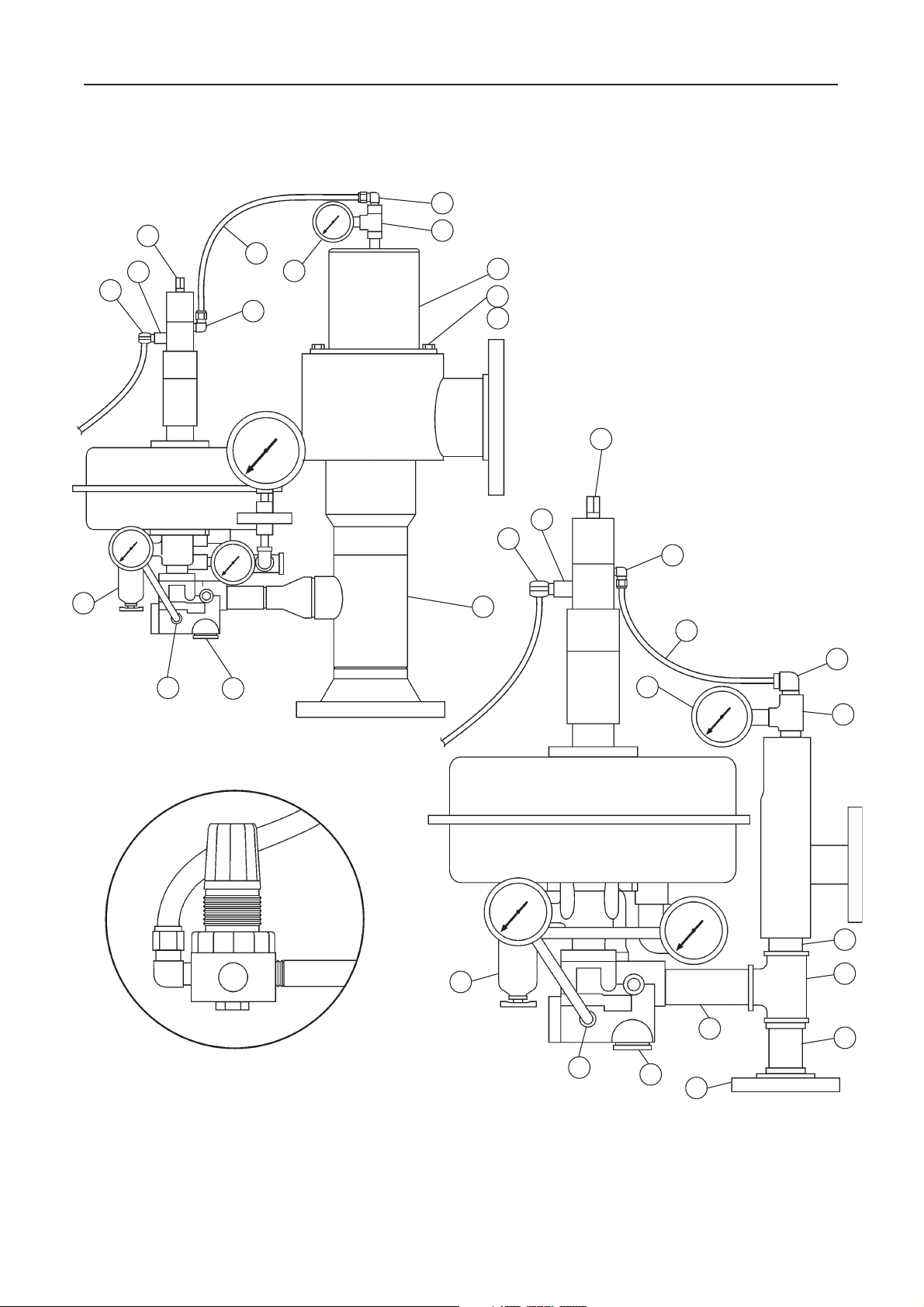
132
Type ACE97
131
SEE INSET
133
111
131
143
131
134
142
159
160
161
131
111
131
131
157
143
132
129
138
1-INCH PAD / 4-INCH DEPAD
TYPICAL DEPAD PILOT
SUPPLY REGULATOR (KEY 140)
E0630
SEE INSET
133
134
148
129
138
146
1-INCH PAD / 1-INCH DEPAD
142
149
150
153
Figure 1. Type ACE97 Pad-Depad Valve Exterior
3
Type ACE97
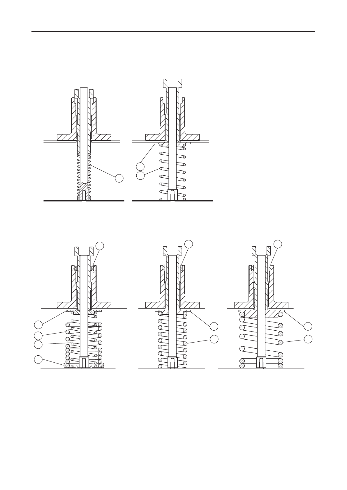
95
97
95
PAD 0.5 TO 3-IN WC (1 TO 7 MBAR)
DEPAD 4 TO 6-IN WC (10 TO 15 MBAR)
PAD 0.5 TO 7-IN WC (1 TO 17 MBAR)
DEPAD 4 TO 10-IN WC (10 TO 25 MBAR)
97
95
96
112
PAD 4 TO 10-IN WC (10 TO 25 MBAR)
DEPAD 16 TO 78-IN WC (10 TO 194 MBAR)
98
PAD 3 TO 13-IN WC (1 TO 32 MBAR)
DEPAD 4 TO 16-IN WC (10 TO 40 MBAR)
98
PAD 0.5 TO 1.4 PSIG (34 TO 97 MBAR)
DEPAD 0.25 TO 1 PSIG (17 TO 69 MBAR)
97
95
PAD 1.0 TO 2.2 PSIG (69 TO 152 MBAR)
DEPAD 0.25 TO 2.0 PSIG (17 TO 138 MBAR)
98
97
95
E0677
Figure 2. Actuator Spring Ranges
4

Type ACE97
166
16
165
42
41
52
2829
27
18
145
148
113
E0631
39
38
37
36
Figure 3. Type ACE97 1/2-inch Pad Valve
E0634
5

Type ACE97
46
29
28
27
16
17
113
26
25
19
24
23
22
21
20
E0632
138
34
18
GROOVE FOR ROLLING
DIAPHRAGM BEAD
E0635
42
41
40
39
38
36
37
35
Figure 4. Type ACE97 1-inch Pad Valve
6

GROOVE FOR ROLLING
DIAPHRAGM BEAD
Type ACE97
42
41
40
39
38
37
36
29
28
27
16
26
49
25
24
51
19
52
113
18
E0635
35
23
22
21
20
E0633
Figure 5. Type ACE97 2-inch Pad Valve
7

Type ACE97
134
86
84
87
143 131
135
90
89
88
75
85
91
83
81
80
76
79
78
77
82
E0636
Figure 6. Depad Main Valve (1-inch)
8

134
87
86
Type ACE97
143 131
135
75
84
83
80
81
76
79
78
85
160
161
82
77
91
E0705
Figure 7. Depad Main Valve (2-inch)
9

Type ACE97
134
87
143 131
135
126
79
85
75
83
80
81
76
79
78
77
84
160
161
82
10
91
E0674
Figure 8. Depad Main Valve (3 and 4-inch)

Type ACE97
106
101
102
103
31
127
104
108
131
135
143
143131
135
143
135
131
105
104
38
111
103
ACTUATOR
109
110
100
107
98
99
120
E0675
Figure 9. Depad Pilot Valve Parts
11

Type ACE97
100
98
28
121
163
119
95
99
114
120
93
93
94
28
31
29
E0676
28
118 117116
27
Figure 10. Actuator Parts
©Fis her C ontro ls Inte rnati onal, I nc., 2002; All R ights Rese rved
Fisher and Fisher Regulators are marks owned by Fisher Controls International, Inc. The Emerson logo is a trade mark and service mark of Emerson Electric Co.
All other marks are the property of their respective owners.
The contents of this publication are presented for informational purposes only, and while every effort has been made to ensure their accuracy, they are not to be construed as warranties or guarantees, express
or implied, regarding the products or services described herein or their use or applicability. We reserve the right to modify or improve the designs or specifications of such products at any time without notice.
For information, contact Fisher Controls, International:
Within USA (800) 588-5853 – Outside USA (972) 542-0132
Italy – (39) 051-4190-606
Singapore – (65) 770-8320
Mexico – (52) 57-28-0888
Printed in U.S.A.
www.FISHERregulators.com
113
 Loading...