

Emerson ACE97 Instruction Manual
Instruction Manual
Form 5665
November 2011
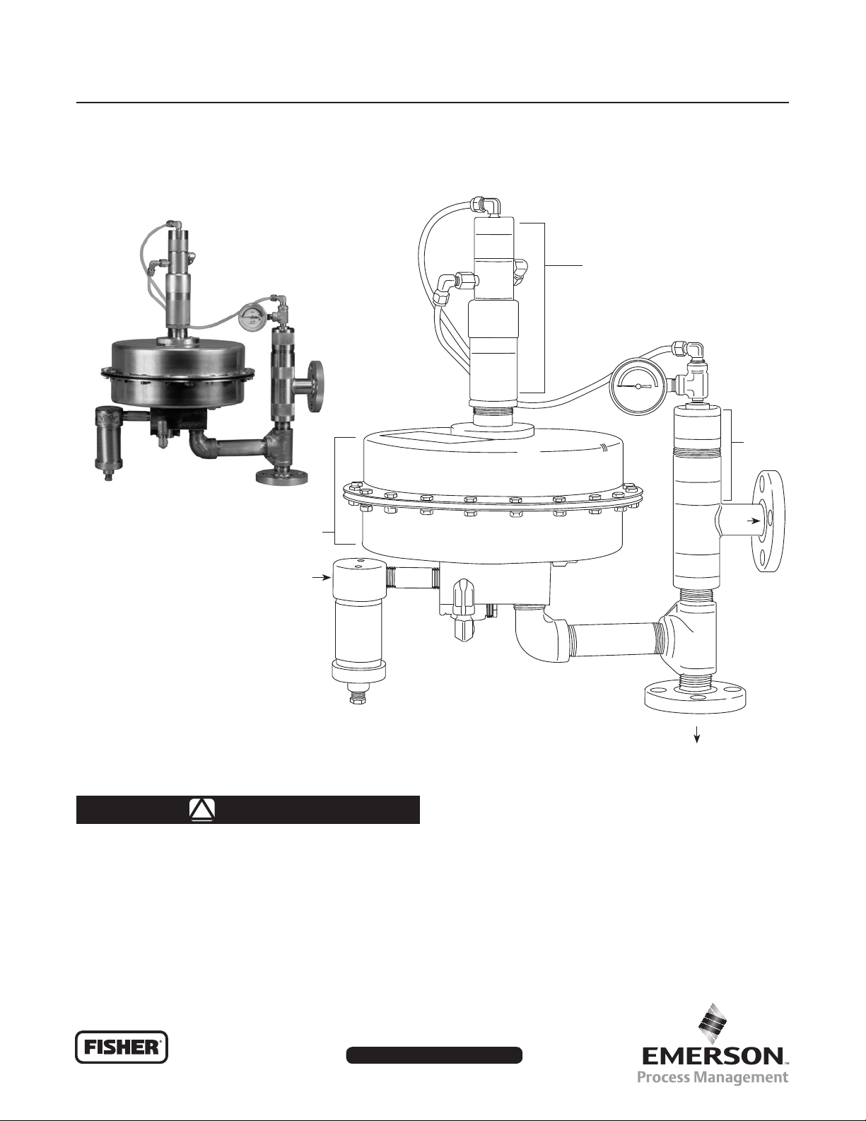
Type ACE97 Pad-Depad Valve
Type ACE97
DEPAD PILOT VALVE
DEPAD
MAIN
VALV E
W8161
ACTUATOR
GAS INLET
Figure 1. Type ACE97 Pad-Depad Valve (NPS 1/2 / DN 15 Pad Valve / 1 NPT Depad Valve Shown)
WARNING
!
Failure to follow these instructions or
to properly install and maintain this
equipment could result in an explosion,
re and/or chemical contamination
causing property damage and personal
injury or death.
VENT
PAD VALVE
TO TANK
Fisher® pad-depad valves must be
installed, operated, and maintained
in accordance with federal, state, and
local codes, rules and regulations,
and Emerson Process Management
Regulator Technologies, Inc. (Regulator
Technologies) instructions.
www.sherregulators.com
D102773X012

Type ACE97
Specications
Ratings and specications for the Type ACE97 Pad-Depad valve are listed in the Specications section below.
Factory specications are stamped on the nameplate fastened to the actuator of the valve.
Pad (Tank Blanketing) Specications
Pad Body Sizes and End Connection Styles
1/2, 1, and 2 NPT
NPS 1/2, 1, and 2 / DN 15, 25, and 50
CL150 RF
Maximum Operating Inlet Pressure
(1)
200 psig / 13,8 bar
Maximum Main Valve Inlet Pressure
(1)
200 psig / 13,8 bar
Inlet Operating Ranges
(1)
NPS 1/2 / DN 15 pad valve:
25 to 200 psig / 1,7 to 13,8 bar
NPS 1 and 2 / DN 25 and 50 pad valves:
25 to 50 psig / 1,7 to 3,4 bar
51 to 120 psig / 3,5 to 8,2 bar
121 to 200 psig / 8,3 to 13,8 bar
Control Pressure Ranges
(1)
See Table 1
Maximum and Minimum Differential Pressures
25 psig / 1,7 bar minimum
200 psig / 13,8 bar maximum
Maximum Backpressure
(1)
20 psig (1,4 bar)
Flow Coefcients for Relief Valve Sizing
(110% of rated Cv)
NPS 1/2 / DN 15:
Cv 0.2 use Cv 0.22
Cv 0.4 use Cv 0.44
NPS 1 / DN 25:
Cv 1 use Cv 1.1
Cv 2 use Cv 2.2
Cv 4 use Cv 4.4
Cv 7.5 use Cv 8.25
Cv 10 use Cv 11
NPS 2 / DN 50:
Cv 20 use Cv 22
Cv 45 use Cv 50
Cv 60 use Cv 66
Depad (Vapor Recovery) Specications
Depad Body Sizes
1 and 2 NPT
NPS 3 and 4 / DN 80 and 100
Depad Pressure Ranges
See Table 1
Valve Coefcients (110% of rated Cv)
1 NPT:
Cv 3 use Cv 3.3
Cv 6 use Cv 7
Cv 12 use Cv 13
Cv 17 use Cv 19
2 NPT:
Cv 20 use Cv 22
Cv 35 use Cv 39
Cv 70 use Cv 77
NPS 3 / DN 80:
Cv 90 use Cv 99
Cv 115 use Cv 127
Cv 140 use Cv 154
NPS 4 / DN 100:
(1)
Cv 150 use Cv 165
Cv 200 use Cv 220
Cv 280 use Cv 308
General Type ACE97 Specications
Pressure Registration
External
Temperature Capabilities
Nitrile (NBR):
-20° to 180°F / -29° to 82°C
Fluorocarbon (FKM):
0° to 212°F / -18° to 100°C
Ethylenepropylene (EPDM - FDA):
-20° to 212°F / -29° to 100°C
Peruoroelastomer (FFKM):
-20° to 212°F / -29° to 100°C
Approximate Weights
NPS 1/2 x 1 x 1 / DN 15 x 25 x 25:
70 pounds / 32 kg
NPS 1 x 2 x 2 / DN 25 x 50 x 50:
105 pounds / 48 kg
NPS 2 x 3 x 3 / DN 50 x 80 x 80:
175 pounds / 79 kg
(1)
1. The pressure/temperature limits in this Instruction Manual or any applicable standard limitation should not be exceeded.
2
E0005
CAGE
INLET
OPEN PILOT
INLET PRESSURE
ATMOSPHERIC PRESSURE
TANK PRESSURE
PILOT LOADING PRESSURE
VENT HEADER PRESSURE
INLET BLEED PRESSURE
LOADING PRESSURE
EXHAUSTED BACK TO TANK
REGULATOR
POPPET
O-RING
SEAT
INLET
BLEED
ROLLING
DIAPHRAGM
INERT GAS IN
MAIN
VALVE
SPRING
ACTUATOR
PAD VALVE
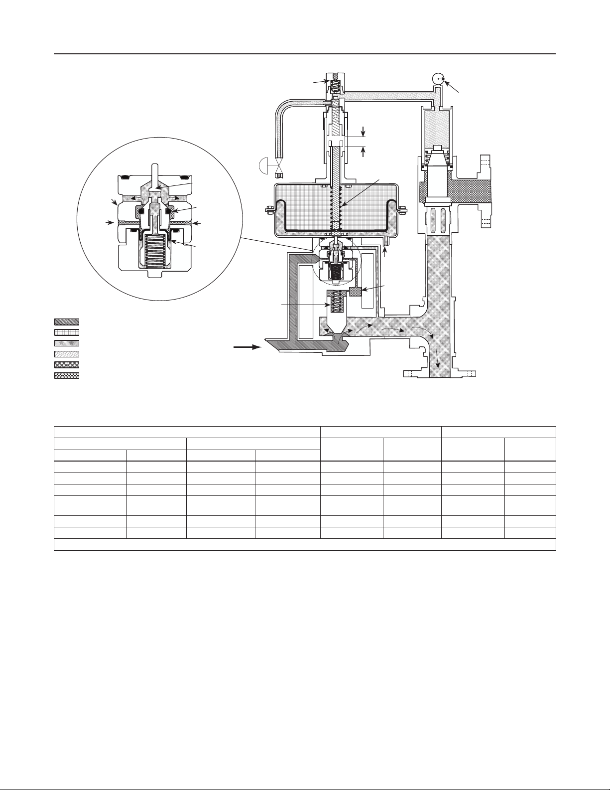
Figure 2. Type ACE97 Pad On / Depad Off
DEPAD PILOT
ADJUSTABLE
DEADBAND
CONTROLLED
PRESSURE
RANGE SPRING
SENSING
CONNECTION
DIAGNOSTIC
PORT
Type ACE97
ON/OFF
DIAGNOSTIC
GAUGE
DEPAD
MAIN
VALVE
VENT
TANK
CONNECTION
Table 1. Actuator Spring Pressure Ranges
CONTROL PRESSURE RANGES SPRING FREE LENGTH SPRING WIRE DIAMETER
Pad Setpoint Depad Setpoint (Above Pad)
inches w.c. mbar inches w.c. mbar
0.5 to 3- 1 to 7 4 to 10 10 to 25 3.08 78,2 0.105 2,67
0.5 to 7 1 to 17 4 to 6 10 to 15 4.0 102 0.092 2,34
3 to 13 7 to 32 4 to 16 10 to 40 3.73 94,7 0.156 3,96
4 to 10 10 to 25
0.5 to 1.4 psig 34 to 97 mbar 0.25 to 1 psig 17 to 69 3.8 96,5 0.250 6,35
1.0 to 2.2 psig 69 to 152 mbar 0.25 to 2 psig 17 to 138 3.8 96,5 0.313 7,95
1. Two nested springs are used (See Figure 12).
(1)
16 to 78 40 to 194
(1)
If a leak develops or if the unit or outlet
continually vents gas, service to the
unit may be required. Failure to correct
INCHES mm INCHES mm
3.73
2.90
94,7
73,7
0.156
0.250
personnel when installing, operating,
and maintaining the Type ACE97
pad-depad valve.
trouble could result in a hazardous
condition. Only a qualied person must
install or service the unit.
Installation, operation, and maintenance
Introduction
Scope of the Manual
procedures performed by unqualied
personnel may result in improper
adjustment and unsafe operation.
Either condition may result in equipment
damage or personal injury. Use qualied
This instruction manual provides installation, startup,
maintenance, and parts ordering information for the
Type ACE97 Pad-Depad valve (Figure 1). The
product photo may vary depending on the size of
the valve ordered.
3,96
6,35
3
Type ACE97
LOADING PRESSURE
EXHAUSTED BACK TO TANK
DEPAD PILOT
ON/OFF
DIAGNOSTIC
GAUGE
CAGE
INLET
E0004
INLET PRESSURE
ATMOSPHERIC PRESSURE
TANK PRESSURE
PILOT LOADING PRESSURE
VENT HEADER PRESSURE
CLOSED PILOT
Product Description
REGULATOR
POPPET
O-RING
SEAT
ROLLING
DIAPHRAGM
CONTROLLED
PRESSURE
RANGE SPRING
ACTUATOR
SENSING
CONNECTION
DIAGNOSTIC
MAIN
VALVE
SPRING
INERT GAS IN
PAD VALVE
PORT
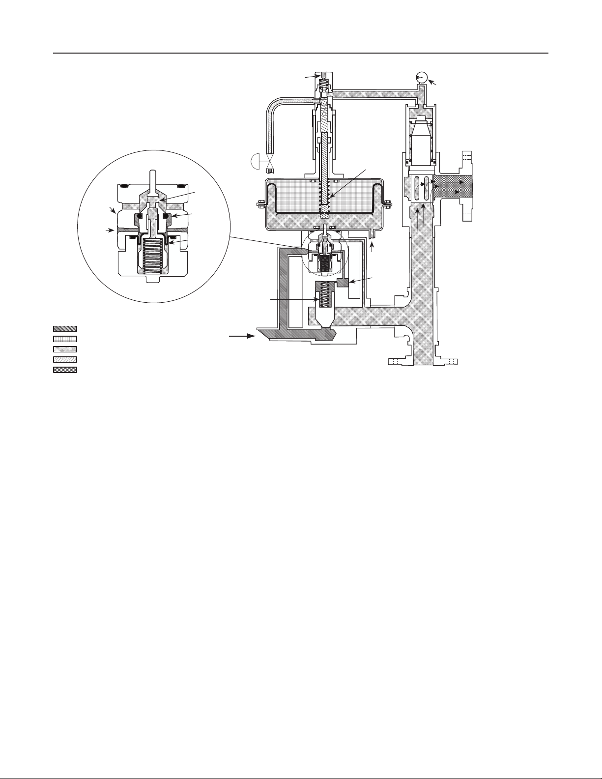
Figure 3. Type ACE97 Pad Off / Depad On
Principle of Operation
DEPAD
MAIN
VALVE
Vent
TANK
CONNECTION
VENT
The Type ACE97 Pad-Depad valve is a self-contained,
pilot-operated valve that maintains a blanket of inert gas
on top of a stored product to protect it from atmospheric
contamination. It reduces combustibility, decreases
vaporization, controls vapor space pressure during
pump-in and pump-out operations, and prevents the
tank from entering a vacuum condition and collapsing
upon itself. The Type ACE97 valve provides excellent
and accurate pressure control of the vapor space in the
tank. Blanketing pressure is kept to a minimum in order
to conserve the use of blanketing gas.
Pad (tank blanketing) is used to describe the process
of replacing the vapor space of a storage tank with
an inert gas.
Depad (vapor recovery) is used to describe the
process of relieving or venting the vapor space as
a result of pressure rise.
Tank and vapor recovery connections are available
to meet most customer requirements. A Single Array
Manifold (S.A.M) provides a single tank and sensing
connection and is required for tanks having a single
nozzle. Accessories include gauges, purge meters,
pressure switches, and check valves.
Type ACE97 pilot-operated valves (except for the
NPS 1/2 / DN 15 pad valve) control the vapor space
pressure over a stored liquid. The unit is stainless
steel and is controlled by a very large actuator
diaphragm. The oversized actuator diaphragm
offers high sensitivity to changes in tank pressure.
When a storage tank cools and tank vapors condense,
Type ACE97 pad (tank blanketing) valves replace the
condensing vapors with an inert gas to prevent internal
tank pressure from decreasing. Positive tank pressure
prevents outside air from contaminating the product
and reduces the possibility of atmospheric pressure
collapsing the tank.
Additionally, Type ACE97 valves provide depad (vapor
recovery) capabilities through the depad main valve
and depad pilot valve. When the temperature outside
the tank rises causing the vapor inside the tank to
expand, Type ACE97 depad valve vents the excess
tank pressure to a safe place.
4
Type ACE97
E0006
CAGE
INLET
CLOSED PILOT
INLET PRESSURE
ATMOSPHERIC PRESSURE
TANK PRESSURE
PILOT LOADING PRESSURE
VENT HEADER PRESSURE
LOADING PRESSURE
EXHAUSTED BACK TO TANK
REGULATOR
POPPET
O-RING
SEAT
ROLLING
DIAPHRAGM
MAIN
VALVE
SPRING
INERT GAS IN
ACTUATOR
PAD VALVE
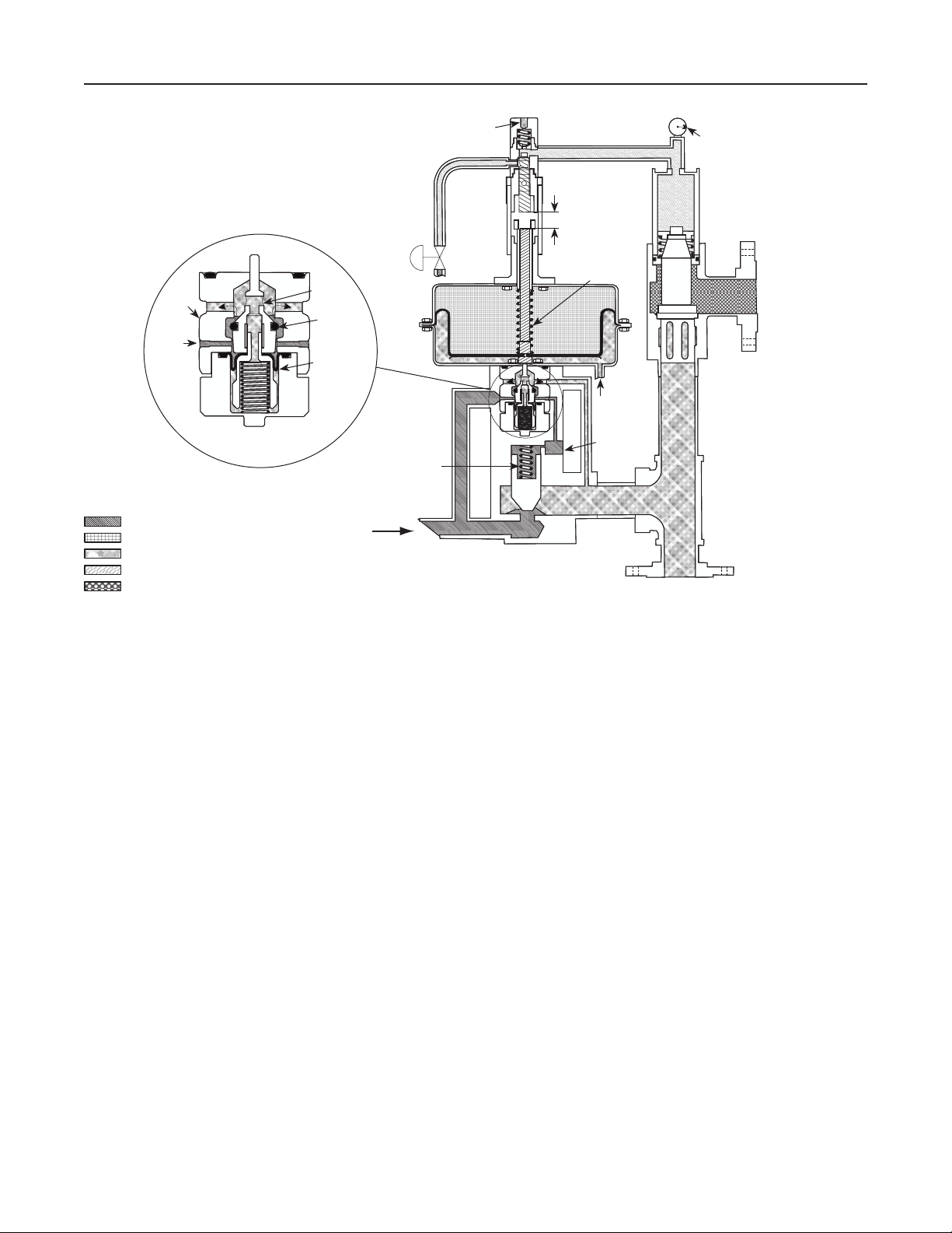
Figure 4. Type ACE97 Pad Off / Depad Off
DEPAD PILOT
ADJUSTABLE
DEADBAND
CONTROLLED
PRESSURE
RANGE SPRING
SENSING
CONNECTION
DIAGNOSTIC
PORT
ON/OFF
DIAGNOSTIC
GAUGE
DEPAD
MAIN
VALVE
TANK
CONNECTION
VENT
NPS 1 and 2 / DN 25 and 50 Pad Valves
(Figure 2)
When tank pressure decreases below the pad setpoint
(due to pump-out operations or thermal cooling), the
actuator diaphragm moves downward pushing open
the pad pilot. This creates ow from the pad loading
chamber to downstream. When pad loading pressure
decreases, the force created by inlet pressure on
the pad main valve plug overcomes the main spring
force and opens the main valve plug allowing ow
through the pad valve to the tank. Once tank pressure
reaches pad setpoint, the pad pilot closes, pad loading
pressure equalizes with inlet pressure and the pad
valve closes.
NPS 1/2 / DN 15 Pad Valve (Not Shown)
The NPS 1/2 / DN 15 pad valve has a main valve only.
When tank pressure decreases below the pad setpoint
the actuator diaphragm moves downward pushing the
valve plug open and allowing ow through the pad
valve to the tank.
Depad (Figure 3)
When tank pressure increases above the depad
setpoint (due to pump-in operations or thermal
heating), the actuator diaphragm moves upward and
pushes open the depad pilot. This releases depad
loading pressure (nitrogen or other supply gas). When
depad pilot loading pressure decreases, the depad
main valve opens by a spring and allows ow from the
tank to the vent or recovery system.
The blanketing (padding) gas is used as the pilot uid.
The link between the actuator and the depad main
valve is provided by the depad pilot valve, which is
located on top of the actuator. The depad pilot valve
is connected to the actuator by an adjustable coupling,
which can be rotated to adjust the depad setpoint. A
locknut is provided on the depad pilot valve to secure
the setpoint adjustment.
5
Type ACE97
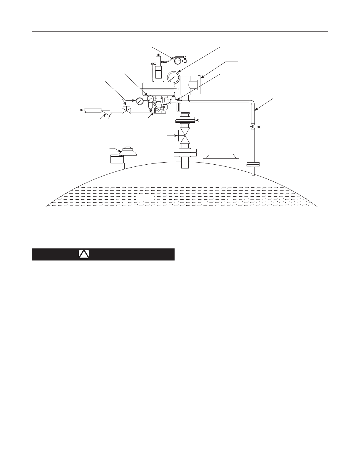
BLANKETING GAS
SUPPLY LINE
E0629
INLET PRESSURE GAUGE
INLET VALVE
LINE STRAINER
NORMAL
TANK VENT
PAD DIAGNOSTIC
GAUGE
BLANKETING GAS
CONNECTION
DEPAD DIAGNOSTIC
GAUGE
TANK VALVE
LIQUID
VAPOR SPACE
TANK VAPOR SPACE
PRESSURE GAUGE
SENSING
CONNECTION
VALVE TANK
CONNECTION
EMERGENCY
TANK VENT
VENT CONNECTION
SENSING LINE
SHUTOFF VALVE
Figure 5. Type ACE97 Pad-Depad Valve Installation
Installation and Startup
WARNING
!
Personal injury, equipment damage, or
leakage due to escaping accumulated
gas or bursting of pressure-containing
parts may result if this gas blanketing
system is overpressured or installed
where service conditions could exceed
the limits given in the Specications
section or on the valve nameplate, or
where conditions exceed any ratings of
the adjacent piping, piping connections,
or compatibility of valve materials with
process uids.
To avoid such injury or damage, provide
pressure-relieving or pressure-limiting
devices (as required by Title 49, Part 192,
of the U.S. Code of Federal Regulations,
by the National Fuel Gas Code Title 54 of
the National Fire Codes of the National
Fire Protection Agency, or by other
applicable codes) to prevent service
conditions from exceeding those limits.
Additionally, physical damage to the
tank blanketing system could result in
personal injury and property damage
due to escaping gas or tank contents.
To avoid such injury and damage,
install the tank blanketing valve in
a safe location.
The Type ACE97 Pad-Depad valve is assembled and
preset to the customer specied pressure and setpoint.
The pressure ranges of the valve are stamped on the
nameplate attached to the upper actuator case.
1. Use qualied personnel when installing, operating,
and maintaining valves. Before installing, inspect
the main valve, pilot, and tubing for any shipment
damage or foreign material that may have
collected. Ensure that the body interior is clean
and the pipelines are free of foreign material.
Apply pipe compound only to the external pipe
threads with a threaded body, or use suitable
line gaskets and good bolting practices with
a anged body.
2. Inspect the nameplate on the upper actuator
case. It displays the model number, serial number,
blanketing gas supply pressure range, maximum
inlet pressure, Cv value, and set pressures. These
6

Type ACE97
must agree with the system that you are Padding
(blanketing) or Depadding (recovering). The serial
number will be needed in any communication with
your local Sales Ofce.
3. Clean the gas padding (blanketing) supply lines of
all dirt and foreign material before connecting
them to the Type ACE97 Pad-Depad valve.
4. The valve should be mounted above the tank
with the actuator case in a horizontal position.
Four connections are required (see Figure 5):
a. Blanketing gas supply to the valve
b. Vapor recovery/process connection (vent)
c. System tank connection
d. Sensing line to the tank
Piping Considerations
Piping must be capable of supporting the weight of
the system. Use pipe supports when necessary.
Refer to Figure 5.
Inlet Piping
The padding (blanketing) gas supply line should be
equipped with a Number 100 mesh strainer to remove
dirt and pipe scale. Inlet piping must be sized to
adequately deliver padding (blanketing) gas at the
specied inlet pressure under full ow conditions.
CAUTION
Undersized piping may inadequately
deliver Padding (blanketing) gas at
the specied inlet pressure under full
ow conditions. This may result in
unacceptable performance under high
demand conditions.
Outlet Piping
Valve outlet is piped into the tank vapor space.
Outlet piping should be self-draining to the tank and
of equal or greater size than the Type ACE97 valve
tank connection. The valve should be situated
above and as close as possible to the tank vapor
space for best performance.
CAUTION
Unnecessarily long or restricted outlet
piping may result in poor setpoint control.
Sensing Line
The sensing line should be 1/2-inch / 13 mm tubing
or pipe, must slope toward the tank, and should not
contain low points (or traps) that could catch liquid.
The sensing line must enter the tank above the liquid
level at a point that senses the vapor space pressure
and is free from turbulence associated with tank
nozzles or vents.
Note
Best control is obtained when both
connections to the tank are separate.
If the tank has only one available
nozzle, contact Regulator Technologies
for alternate methods of installation.
A Single Array Manifold (S.A.M.) is
available for such situations.
Vent Connection
The vent connection must be self-draining, facing
away from the valve, and of equal or greater size than
the valve tank connection.
Tank Venting
The tank may require normal and emergency vents.
The Type ACE97 Pad-Depad valve does not perform
these functions, it only controls the vapor space
pressure under process conditions.
Diagnostic Gauges
An on/off diagnostic gauge is mounted on the depad
main valve at the inlet to the cylinder. The face on
the gauge is marked to indicate whether the main pad
valve is opened, closed, or throttled.
Shutoff Valves
Note
Safety considerations may dictate
shutoff valves between the tank and
Type ACE97 valve.
Inlet (isolation) valves are desirable for servicing the
Type ACE97 valve. If this valve was not ordered with
an inlet pressure gauge, it is advisable to install a
gauge between the inlet isolation (full-port) valve and
the padding (blanketing) valve.
7
Type ACE97
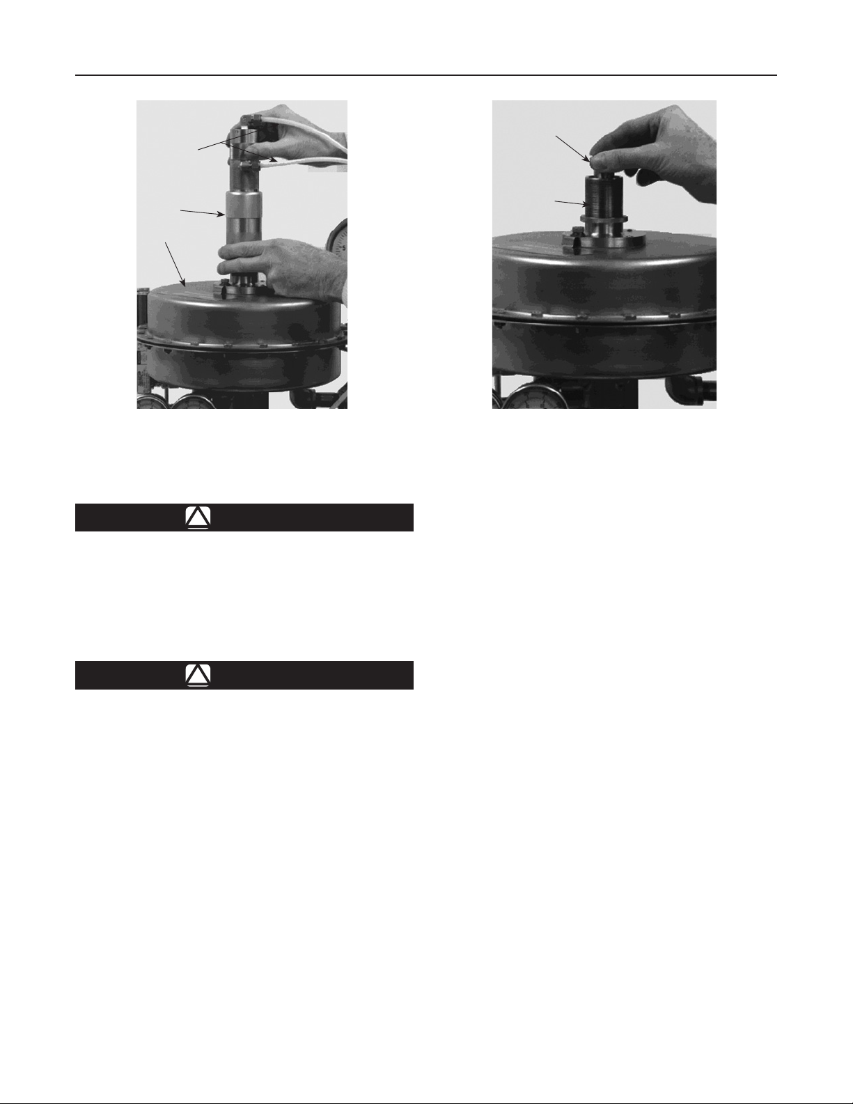
TUBING
ADJUSTING SCREW
COUPLING
ACTUATOR
E0678
Figure 6. Unthreading the Adjusting Coupling
Startup, Adjustment, and Shutdown
CAUTION
If required, tank vents (normal
and emergency) must be in place
and operating.
LOCKNUT
E0679
Figure 7. Changing the Pad Setpoint
Adjustment
The setpoint of this unit is factory set. If an adjustment
is to be made, it should be made in small increments
while the unit is controlling tank pressure. It is difcult
to make eld adjustments due to the slow changes in
tank pressure.
To change the pad (blanketing) setpoint:
Startup
CAUTION
Always open the tank shutoff valve prior
to the inlet shutoff valve. Failure to do
so could result in inlet pressure being
applied to the actuator casing, potentially
damaging it. Refer to Figure 5.
1. Open the tank and sensing line shutoff valves
(between the Type ACE97 valve and tank).
2. A tank vapor space pressure gauge should be
installed and visible.
3. Slowly open the inlet shutoff valve (to the pad
valve) and leave it fully open.
4. Monitor the tank vapor space pressure.
1. Disconnect the tubing from the depad pilot valve
(See Figure 6).
2. Loosen the locknut (See Figure 7), but maintain its
position in relation to the adjusting coupling.
Doing so leaves the depad setpoint unchanged.
3. Separate the depad pilot valve from the actuator
by unthreading and removing.
4. Unthread and remove the adjusting coupling.
5. Increase the pad setpoint by turning the adjusting
screw clockwise. (Turning the screw counterclockwise
decreases the setpoint). See Figure 7.
6. Replace the depad adjusting collar against the
locknut to re-establish the depad setpoint.
To change the depad setpoint:
1. Loosen the locknut below the adjusting coupling.
2. Rotate the collar to change the setpoint. (The
bottom of the coupling—nearest the locknut—is
left-hand threaded).
3. Tighten the locknut.
8

Type ACE97
Table 2. Diagnostic Analysis Pressure Ranges
DIAGNOSTIC STATUS
Equal to inlet supply pressure
Slightly below inlet supply pressure
Well below inlet supply pressure
Pilot and main valves are closed.
Tank pressure is at or above set pressure.
Pilot valve supplies gas to tank. Tank
pressure is just below set pressure.
Pilot and main valves are both
supplying gas to the tank. Tank
pressure is below setpoint.
Shutdown
In any installation it is important to open and close
valves slowly and to close the inlet shutoff valve rst
when shutting down the system.
Maintenance
Valve parts are subject to normal wear and must be
inspected and replaced as necessary. The frequency
of inspection and replacement of parts depend on the
severity of service conditions and the requirements
of local, state, and federal regulations. Due to the
care Regulator Technologies takes in meeting all
manufacturing requirements, use only replacement parts
manufactured or furnished by Regulator Technologies.
All O-rings, gaskets, and seals should be lubricated
with a good grade of general purpose lubricant and
installed gently rather than forced into position.
Approved lubricants, sealants, thread protectors,
and adhesives are as follows:
Lubricants: Dow Corning® #111, Dow
Corning® #3452 Chemical Resistant Lubricant
Thread Protector: Anti-Seize
Sealant: Loctite® PST #592,
Polytetrauoroethylene (PTFE) Tape
Adhesive: Loctite® #222
Be certain that nameplates are updated to accurately
indicate any eld changes in equipment, materials,
service conditions, or pressure settings.
Monthly Maintenance
1. Visually inspect the unit to ensure tight
connections, tight seals, and safe operation.
2. Observe the pad and depad (tank blanketing
and vapor recovery) pressures.
3. Inspect the inlet pressure for the proper range
(stamped on the valve nameplate).
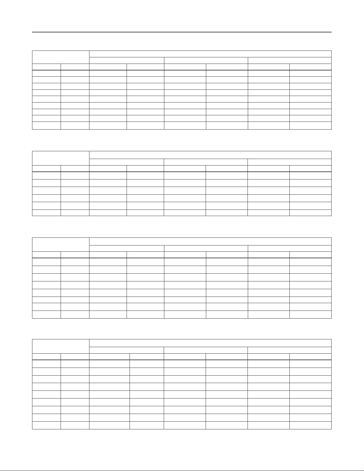
Table 3. Diagnostics Table: Cv 1 through 4, Inlet Pressure Range Spring 25 to 50 psig / 1,7 to 3,4 bar
ACTUAL INLET SUPPLY
PRESSURE TO VALVE
psig bar psig bar psig bar psig bar
25 1,7 24 1,7 9 0,62 2 0,14
30 2,1 29 2,0 13 0,90 6 0,41
35 2,4 34 2,3 16 1,1 9 0,62
40 2,8 39 2,7 20 1,4 13 0,90
45 3,1 44 3,0 24 1,7 17 1,2
50 3,4 49 3,4 28 1,9 21 1,4
Table 4. Diagnostics Table: Cv 1 through 4, Inlet Pressure Range Spring 51 to 120 psig / 3,5 to 8,3 bar
ACTUAL INLET SUPPLY
PRESSURE TO VALVE
psig bar psig bar psig bar psig bar
51 3,5 50 3,4 29 2,0 5 0,35
60 4,1 59 4,1 36 2,5 12 0,83
70 4,8 69 4,8 43 3,0 19 1,3
80 5,5 79 5,4 51 3,5 27 1,9
90 6,2 89 6,1 59 4,1 34 2,3
100 6,9 99 6,8 66 4,5 42 2,9
110 7,6 109 7,5 74 5,1 50 3,4
120 8,3 119 8,2 81 5,6 57 3,9
Pressure when Pilot Starts to Open Pressure when Main Valve Starts to Open Pressure when Main Valve is Fully Open
Pressure when Pilot Starts to Open Pressure when Main Valve Starts to Open Pressure when Main Valve is Fully Open
DIAGNOSTIC PORT PRESSURE
DIAGNOSTIC PORT PRESSURE
9
Type ACE97
Table 5. Diagnostics Table: Cv 1 through 4, Inlet Pressure Range Spring 121 to 200 psig / 8,3 to 13,8 bar
ACTUAL INLET SUPPLY
PRESSURE TO VALVE
psig bar psig bar psig bar psig bar
121 8,3 120 8,3 74 5,1 30 2,1
130 9,0 129 8,9 81 5,6 37 2,5
140 9,6 139 9,6 88 6,1 45 3,1
150 10,3 149 10,3 96 6,6 53 3,6
160 11,0 159 10,9 104 7,2 60 4,1
170 11,7 169 11,7 111 7,6 68 4,7
180 12,4 179 12,3 119 8,2 75 5,2
190 13,1 189 13,0 127 8,8 83 5,7
200 13,8 199 13,7 134 9,2 91 6,3
Pressure when Pilot Starts to Open Pressure when Main Valve Starts to Open Pressure when Main Valve is Fully Open
Table 6. Diagnostics Table: Cv 7.5 through 10, Inlet Pressure Range Spring 25 to 50 psig / 1,7 to 3,4 bar
DIAGNOSTIC PORT PRESSURE
ACTUAL INLET SUPPLY
PRESSURE TO VALVE
psig bar psig bar psig bar psig bar
25 1,7 24 1,7 11 0,76 0 0,00
30 2,1 29 2,0 14 0,96 3 0,21
35 2,4 34 2,3 17 1,2 6 0,41
40 2,8 39 2,7 21 1,4 9 0,62
45 3,1 44 3,0 24 1,7 13 0,89
50 3,4 49 3,4 27 1,9 16 1,1
Pressure when Pilot Starts to Open Pressure when Main Valve Starts to Open Pressure when Main Valve is Fully Open
DIAGNOSTIC PORT PRESSURE
Table 7. Diagnostics Table: Cv 7.5 through 10, Inlet Pressure Range Spring 51 to 120 psig / 3,5 to 8,3 bar
ACTUAL INLET SUPPLY
PRESSURE TO VALVE
psig bar psig bar psig bar psig bar
51 3,5 50 3,4 24 1,7 3 0,21
60 4,1 59 4,1 30 2,1 9 0,62
70 4,8 69 4,8 36 2,5 15 1,0
80 5,5 79 5,4 42 2,9 22 1,5
90 6,2 89 6,1 49 3,4 28 1,9
100 6,9 99 6,8 55 3,8 34 2,3
110 7,6 109 7,5 61 4,2 41 2,8
120 8,3 119 8,2 68 4,7 47 3,2
Pressure when Pilot Starts to Open Pressure when Main Valve Starts to Open Pressure when Main Valve is Fully Open
DIAGNOSTIC PORT PRESSURE
Table 8. Diagnostics Table: Cv 7.5 through 10, Inlet Pressure Range Spring 121 to 200 psig / 8,3 to 13,8 bar
ACTUAL INLET SUPPLY
PRESSURE TO VALVE
psig bar psig bar psig bar psig bar
121 8,3 120 8,3 63 4,3 31 2,1
130 9,0 129 9,0 69 4,8 37 2,5
140 9,6 139 9,6 75 5,2 43 3,0
150 10,3 149 10,3 82 5,6 49 3,4
160 11,0 159 10,9 88 6,1 56 3,9
170 11,7 169 11,7 94 6,9 62 4,3
180 12,4 179 12,3 101 7,0 68 4,7
190 13,1 189 13,0 107 7,4 75 5,2
200 13,8 199 13,7 113 7,8 81 5,6
Pressure when Pilot Starts to Open Pressure when Main Valve Starts to Open Pressure when Main Valve is Fully Open
10
DIAGNOSTIC PORT PRESSURE
 Loading...