

Page 1
SPEC. NO.
MODEL
581127000
710NPBA
NetSure™ +24V DC Power System
Installation Instructions
IM581127000 (Issue AB, March 22, 2012)
Page 2

Business-Critical Continuity™, Emerson Network Power, and the Emerson Network
Power logo are trademarks and service marks of Emerson Electric Co.
NetSure™, NetSpan™, NetReach™, NetXtend™, and NetPerform™
are trademarks of Emerson Network Power, Energy Systems, North America, Inc.
All other trademarks are the property of their respective owners.
The products covered by this instruction manual are manufactured and/or
sold by Emerson Network Power, Energy Systems, North America, Inc.
The information contained in this document is subject to change without notice and may not be
suitable for all applications. While every precaution has been taken to ensure the accuracy and
completeness of this document, Emerson Network Power, Energy Systems, North America, Inc.
assumes no responsibility and disclaims all liability for damages resulting from use of this information
or for any errors or omissions. Refer to other local practices or building codes as applicable for the correct
methods, tools, and materials to be used in performing procedures not specifically described in this document.
This document is the property of Emerson Network Power, Energy Systems, North America, Inc.
and contains confidential and proprietary information owned by Emerson Network Power, Energy
Systems, North America, Inc. Any copying, use or disclosure of it without the written permission
of Emerson Network Power, Energy Systems, North America, Inc. is strictly prohibited.
Copyright © 2012, Emerson Network Power, Energy Systems, North America, Inc.
All rights reserved throughout the world.
Page 3

Installation Instructions IM581127000
Spec. No. 581127000 (Model 710NPBA) Issue AB, March 22, 2012
TABLE OF CONTENTS
CONTENTS PAGE
IMPORTANT SAFETY INSTRUCTIONS .................................................................................. iv
General Safety .................................................................................................................................................... iv
Voltages .............................................................................................................................................................. iv
Battery ................................................................................................................................................................. iv
Circuit Card Handling ........................................................................................................................................... v
STATIC WARNING ................................................................................................................... vi
CHAPTER 1. GENERAL INFORMATION AND INSTALLATION CHECKLIST ........................ 1
Customer Documentation Package ..................................................................................................................... 1
Installation Acceptance Checklist ........................................................................................................................ 1
CHAPTER 2. INSTALLING THE SYSTEM ................................................................................ 3
General Requirements ......................................................................................................................................... 3
Securing the Relay Rack to the Floor .................................................................................................................. 3
Ventilation Requirements .............................................................................................................................. 3
Relay Rack Floor Mounting Dimensions ....................................................................................................... 4
Mounting System Components in an Equipment Rack ....................................................................................... 7
Mounting the Distribution Cabinet with Module Mounting Assembly ............................................................ 7
Installing a List 93 Battery Tray ................................................................................................................... 10
Installing Optional Lug Adapter Busbar Kits, Part Nos. 534449 and 514714 .................................................... 14
Installing Circuit Breakers and Fuses ................................................................................................................ 16
Installing Bullet Nose Type Fuseholders and TPS/TLS Fuses ................................................................... 16
Installing Bullet Nose Type Circuit Breakers ............................................................................................... 18
Installing an Optional Bullet Nose Type 6-Position GMT Distribution Fuse Block ...................................... 19
Installing TPH Fuses ................................................................................................................................... 21
Installing TPL-B Fuses ................................................................................................................................ 22
Installing GJ/218 Circuit Breakers ............................................................................................................... 23
CHAPTER 3. SETTING JUMPERS AND SWITCH OPTIONS ................................................. 28
Circuit Card Locations ........................................................................................................................................ 28
Jumpers on System Interface Circuit Card ........................................................................................................ 29
Controller Power Option .............................................................................................................................. 29
Internal/External Battery Monitoring ............................................................................................................ 29
Switch Settings on IB2 Interface Board ............................................................................................................. 31
Switch Setting on Optional EIB Interface Board ................................................................................................ 31
Switch Setting on SM-DU+ ................................................................................................................................ 34
CHAPTER 4. MAKING ELECTRICAL CONNECTIONS .......................................................... 36
Important Safety Instructions ............................................................................................................................. 36
Wiring Considerations ........................................................................................................................................ 36
Relay Rack Grounding Connection (Frame Ground) ......................................................................................... 37
AC Input and AC Input Equipment Grounding Connections .............................................................................. 38
Connections to Factory Installed Module Mounting Shelves ...................................................................... 38
Table of Contents Page i
This document is property of Emerson Network Power, Energy Systems, North America, Inc. and contains confidential and proprietary information owned by Emerson Network Power, Energy
Systems, North America, Inc. Any copying, use, or disclosure of it without the written permission of Emerson Network Power, Energy Systems, North America, Inc. is strictly prohibited.
Page 4

IM581127000 Installation Instructions
Issue AB, March 22, 2012 Spec. No. 581127000 (Model 710NPBA)
Connections to Field Expansion Module Mounting Assembly .................................................................... 47
External Alarm, Reference, Monitoring, and Control Connections .................................................................... 49
Circuit Card Locations ................................................................................................................................. 49
System Interface Circuit Card ...................................................................................................................... 50
IB2 (ACU+ Controller Interface Board) ........................................................................................................ 52
Optional EIB (ACU+ Controller Extended Interface Board) ......................................................................... 55
Optional SM-DU+ and Shunt Interface Board ............................................................................................. 59
Optional SM-Temp Module .......................................................................................................................... 59
Ethernet Connection .......................................................................................................................................... 61
Control Bus Connections between Controller and Module Mounting Shelves .................................................. 62
Connecting List 60 Converter Output Jumpers .................................................................................................. 64
Load Connections .............................................................................................................................................. 66
Recommended Torques .............................................................................................................................. 66
Load Connections to Single Voltage Distribution Panels ............................................................................ 67
Load Connections to Dual Voltage Distribution Panels ............................................................................... 71
Load Connections to Return Bar ................................................................................................................. 73
Load Connections to GMT Distribution Fuse Block ..................................................................................... 73
Battery Connections ........................................................................................................................................... 74
Important Safety Instructions ....................................................................................................................... 74
Recommended Torques .............................................................................................................................. 74
Battery Connections to Optional Battery Disconnect Distribution Panels ................................................... 74
Battery Connections to Distribution Cabinet Battery Busbars ..................................................................... 78
Battery Connections to Optional Battery Landing Busbar Kit P/N 541371 ................................................. 79
Battery Connections to Optional Battery Landing Busbar Kit P/N 550265 ................................................. 80
Installing and Connecting Batteries in List 93 Battery Tray (if furnished) .......................................................... 81
Important Safety Instructions ....................................................................................................................... 81
Battery Manufacturer Information ................................................................................................................ 81
Installing Battery Landing Busbar Kit P/N 541371 (List 21) or 550265 (List 22, 23, or 24) ........................ 82
Wiring to the Battery Tray ............................................................................................................................ 85
Installing and Connecting Batteries ............................................................................................................. 88
CHAPTER 5. INSTALLING THE MODULES AND INITIALLY STARTING THE SYSTEM ..... 90
Installing the Rectifier and DC-DC Converter Modules ..................................................................................... 90
Initially Starting, Configuring, and Checking System Operation ........................................................................ 92
Important Safety Instructions ....................................................................................................................... 92
Initial Startup Preparation ............................................................................................................................ 92
Initially Starting the System ......................................................................................................................... 92
ACU+ Controller Initialization....................................................................................................................... 93
Verifying the Configuration File ................................................................................................................... 95
Checking Basic System Settings ................................................................................................................. 95
Checking System Status ............................................................................................................................. 97
Changing Battery Capacity Rating in the ACU+ .......................................................................................... 98
Configuring the ACU+ Identification of Rectifiers and Assigning which Input Phase is Connected
to the Rectifiers ............................................................................................................................................ 98
Configuring the ACU+ Identification of Converter Modules ......................................................................... 99
Page ii Table of Contents
This document is property of Emerson Network Power, Energy Systems, North America, Inc. and contains confidential and proprietary information owned by Emerson Network Power, Energy
Systems, North America, Inc. Any copying, use, or disclosure of it without the written permission of Emerson Network Power, Energy Systems, North America, Inc. is strictly prohibited.
Page 5

Installation Instructions IM581127000
Spec. No. 581127000 (Model 710NPBA) Issue AB, March 22, 2012
ACU+ Alarm Relay Check ......................................................................................................................... 100
Final Steps ................................................................................................................................................. 108
REVISION RECORD .............................................................................................................. 110
Table of Contents Page iii
This document is property of Emerson Network Power, Energy Systems, North America, Inc. and contains confidential and proprietary information owned by Emerson Network Power, Energy
Systems, North America, Inc. Any copying, use, or disclosure of it without the written permission of Emerson Network Power, Energy Systems, North America, Inc. is strictly prohibited.
Page 6

IM581127000 Installation Instructions
Issue AB, March 22, 2012 Spec. No. 581127000 (Model 710NPBA)
IMPORTANT SAFETY INSTRUCTIONS
GENERAL SAFETY
Danger: YOU MUST FOLLOW APPROVED SAFETY PROCEDURES.
Performing the following procedures may expose you to hazards. These
procedures should be performed by qualified technicians familiar with the
hazards associated with this type of equipment. These hazards may
include shock, energy, and/or burns. To avoid these hazards:
a) The tasks should be performed in the order indicated.
b) Remove watches, rings, and other metal objects.
c) Prior to contacting any uninsulated surface or termination, use a
voltmeter to verify that no voltage or the expected voltage is present.
d) Wear eye protection, and use recommended tools.
e) Use double insulated tools appropriately rated for the work to be
performed.
Caution: Performing maintenance and/or troubleshooting procedures may
interrupt power to the loads, if battery reserve is not sufficient.
VOLTAGES
AC Input Voltages
Danger: This system operates from AC voltage capable of producing fatal
DC Input/Output Voltages
Danger: This system produces DC Power and may require battery to be connected
BATTERY
Danger: Correct polarity must be observed when connecting battery leads.
Danger: Special safety precautions are required for procedures involving
electrical shock. AC input power must be completely disconnected from
the branch circuits wiring used to provide power to the system before any
AC electrical connections are made. DO NOT apply AC power to the
system until all electrical connections have been completed and checked.
to it. Although the DC voltage is not hazardously high, the rectifiers
and/or battery can deliver large amounts of current. Exercise extreme
caution not to inadvertently contact or have any tool inadvertently contact
a battery terminal or exposed wire connected to a battery terminal.
NEVER allow a metal object, such as a tool, to contact more than one
termination or battery terminal at a time, or to simultaneously contact a
termination or battery terminal and a grounded object. Even a momentary
short circuit can cause sparking, explosion, and injury.
handling, installing, and servicing batteries. Observe all battery safety
precautions in this manual and in the battery instruction manual. These
precautions should be followed implicitly at all times. Remove watches,
rings, and other metal objects before connecting battery leads.
Page iv Important Safety Instructions
This document is property of Emerson Network Power, Energy Systems, North America, Inc. and contains confidential and proprietary information owned by Emerson Network Power, Energy
Systems, North America, Inc. Any copying, use, or disclosure of it without the written permission of Emerson Network Power, Energy Systems, North America, Inc. is strictly prohibited.
Page 7

Installation Instructions IM581127000
Spec. No. 581127000 (Model 710NPBA) Issue AB, March 22, 2012
CIRCUIT CARD HANDLING
Warning: Installation or removal of the circuit cards requires careful handling.
Before handling any circuit card, read and follow the instructions
contained on the Static Warning Page.
Important Safety Instructions Page v
This document is property of Emerson Network Power, Energy Systems, North America, Inc. and contains confidential and proprietary information owned by Emerson Network Power, Energy
Systems, North America, Inc. Any copying, use, or disclosure of it without the written permission of Emerson Network Power, Energy Systems, North America, Inc. is strictly prohibited.
Page 8

IM581127000 Installation Instructions
Issue AB, March 22, 2012 Spec. No. 581127000 (Model 710NPBA)
STATIC WARNING
The printed circuit cards used in this equipment contain static sensitive components. The warnings listed below
must be observed to prevent damage to these components. Disregarding any of these warnings may result in
personal injury or damage to the equipment.
1. Strictly adhere to the procedures provided in this document.
2. Before touching any static sensitive component or printed circuit card containing such a component,
discharge all static electricity from yourself by wearing a wrist strap grounded through a one megohm
resistor. Some wrist straps, such as Emerson Network Power Part Number 631810600, have a built-in
one megohm resistor; no external resistor is necessary. Read and follow wrist strap manufacturer’s
instructions outlining use of a specific wrist strap.
3. Do not touch the traces or components on a printed circuit card containing static sensitive components.
Handle the printed circuit card only by the edges that do not have connector pads.
4. After removing a printed circuit card containing a static sensitive component, place the printed circuit card
only on conductive or anti-static material such as conductive foam, conductive plastic, or aluminum foil.
Do not use ordinary Styrofoam or ordinary plastic.
5. Store and ship static sensitive devices or printed circuit cards containing such components only in static
shielding containers.
6. If necessary to repair a printed circuit card containing a static sensitive component, wear an appropriately
grounded wrist strap, work on a conductive surface, use a grounded soldering iron, and use grounded
test equipment.
Page vi Static Warning
This document is property of Emerson Network Power, Energy Systems, North America, Inc. and contains confidential and proprietary information owned by Emerson Network Power, Energy
Systems, North America, Inc. Any copying, use, or disclosure of it without the written permission of Emerson Network Power, Energy Systems, North America, Inc. is strictly prohibited.
Page 9

Installation Instructions IM581127000
Spec. No. 581127000 (Model 710NPBA) Issue AB, March 22, 2012
CHAPTER 1. GENERAL INFORMATION AND INSTALLATION CHECKLIST
CUSTOMER DOCUMENTATION PACKAGE
This document (IM581127000) provides Installation Instructions for NetSure™ Power
System Model 710NPBA, Spec. No. 581127000.
The complete Customer Documentation Package consists of…
Bound System Installation Manual
Power System Installation Instructions: IM581127000
Power System Quick Start Guide: QS581127000
Bound ACU+ Controller User Manual
ACU+ Controller User Instructions: UM1M820BNA
(includes instructions
for 1M820DNA Controller)
USB Drive with All Customer Documentation
Power System Installation Instructions: IM581127000
Power System Quick Start Guide: QS581127000
Power System User Instructions: UM581127000
Power System “System Application Guide”: SAG581127000
Power Data Sheet: PD588705200
(PD588705201, PD588705202,
PD588705203, PD588705204)
Rectifier Instructions: UM1R243000
Converter Instructions: UM1C24481500
Engineering Drawings
Also provided on the USB drive is an ACU+ configuration drawing and the ACU+
configuration files loaded into the ACU+ as shipped.
INSTALLATION ACCEPTANCE CHECKLIST
Provided below is an Installation Acceptance Checklist. This checklist helps ensure
proper installation and initial operation of the system. As the procedures presented in
Chapters 2 through 5 of this document are completed, check the appropriate box on this
list. If the procedure is not required to be performed for your installation site, also check
the box in this list to indicate that the procedure was read. When installation is done,
ensure that each block in this list has been checked. Some of these procedures may
have been factory performed for you.
Note: The system is not powered up until the end of this checklist.
Note: Some of these procedures may have been performed at the factory for you.
Chapter 1. General Information and Installation Checklist Page 1
This document is property of Emerson Network Power, Energy Systems, North America, Inc. and contains confidential and proprietary information owned by Emerson Network Power, Energy
Systems, North America, Inc. Any copying, use, or disclosure of it without the written permission of Emerson Network Power, Energy Systems, North America, Inc. is strictly prohibited.
Page 10

IM581127000 Installation Instructions
Issue AB, March 22, 2012 Spec. No. 581127000 (Model 710NPBA)
Chapter 2. Installing the System
Relay Rack Secured to Floor
System Components Mounted in Relay Rack (if required)
Optional Lug Adapter Busbar Kits Installed
Circuit Breakers Installed
Fuses Installed
Chapter 3. Setting Jumper and Switch Options
Jumpers on System Interface Circuit Card Set
Switch Setting on IB2 Interface Board Set
Switch Setting on Optional EIB Interface Board Set
Switch Setting on Optional SM-DU+ Set
Chapter 4. Making Electrical Connections
Relay Rack Grounding Connection (Frame Ground) Made
AC Input and AC Input Equipment Grounding Connections Made
External Alarm, Reference, Monitoring, and Control Connections Made
Ethernet Connection Made (if required)
Load Connections Made
Battery Connections Made
Batteries Installed and Connected in an optional Battery Tray (if furnished)
Optional Battery Tray Front Battery Covers Installed (if furnished)
Optional Battery Tray Circuit Breaker Guards Installed (if furnished)
Chapter 5. Installing the Modules and Initially Starting the System
Rectifier and Converter Modules Installed
System Started, Configured, and Checked
Page 2 Chapter 1. General Information and Installation Checklist
This document is property of Emerson Network Power, Energy Systems, North America, Inc. and contains confidential and proprietary information owned by Emerson Network Power, Energy
Systems, North America, Inc. Any copying, use, or disclosure of it without the written permission of Emerson Network Power, Energy Systems, North America, Inc. is strictly prohibited.
Page 11

Installation Instructions IM581127000
Spec. No. 581127000 (Model 710NPBA) Issue AB, March 22, 2012
CHAPTER 2. INSTALLING THE SYSTEM
GENERAL REQUIREMENTS
This product is intended only for installation in a Restricted Access Location on or
above a non-combustible surface.
This product must be located in a Controlled Environment with access to Crafts
persons only.
This product is intended for installation in Network Telecommunication Facilities (CO,
vault, hut, or other environmentally controlled electronic equipment enclosure).
This product is intended for connection to the common bonding network in a Network
Telecommunication Facility (CO, vault, hut, or other environmentally controlled
electronic equipment enclosure).
The installer should be familiar with the installation requirements and techniques to
be used in securing the relay rack to the floor.
Clearance requirements are:
a) Recommended minimum aisle space clearance for the front of the relay rack is
2' 6".
b) Recommended minimum aisle space clearance for the rear of the relay rack is
2’ 0” for any of the following conditions:
1) Addition of a Module Mounting Assembly in the field.
2) Making AC input connections to the field expansion Module Mounting
Assembly.
For all other conditions, recommended minimum aisle space clearance for the rear of
the relay rack is that which is specified for proper module mounting assembly
ventilation. Refer to Module Mounting Assembly Power Data Sheet PD588705200
(PD588705201, PD588705202, PD588705203, PD588705204) for ventilation
spacing requirements.
Note: Minimum spacing specified for ventilation may not permit replacement of
certain components such as module mounting shelves.
SECURING THE RELAY RACK TO THE FLOOR
All equipment cabinets are factory mounted to the relay rack or shipping brackets
specified when ordered.
Secure the relay rack to the floor per site requirements. Refer to the General
Requirements section at the beginning of this chapter.
Ventilation Requirements
Refer to the General Requirements section at the beginning of this chapter.
Chapter 2. Installing the System Page 3
This document is property of Emerson Network Power, Energy Systems, North America, Inc. and contains confidential and proprietary information owned by Emerson Network Power, Energy
Systems, North America, Inc. Any copying, use, or disclosure of it without the written permission of Emerson Network Power, Energy Systems, North America, Inc. is strictly prohibited.
Page 12
IM581127000 Installation Instructions
Issue AB, March 22, 2012 Spec. No. 581127000 (Model 710NPBA)
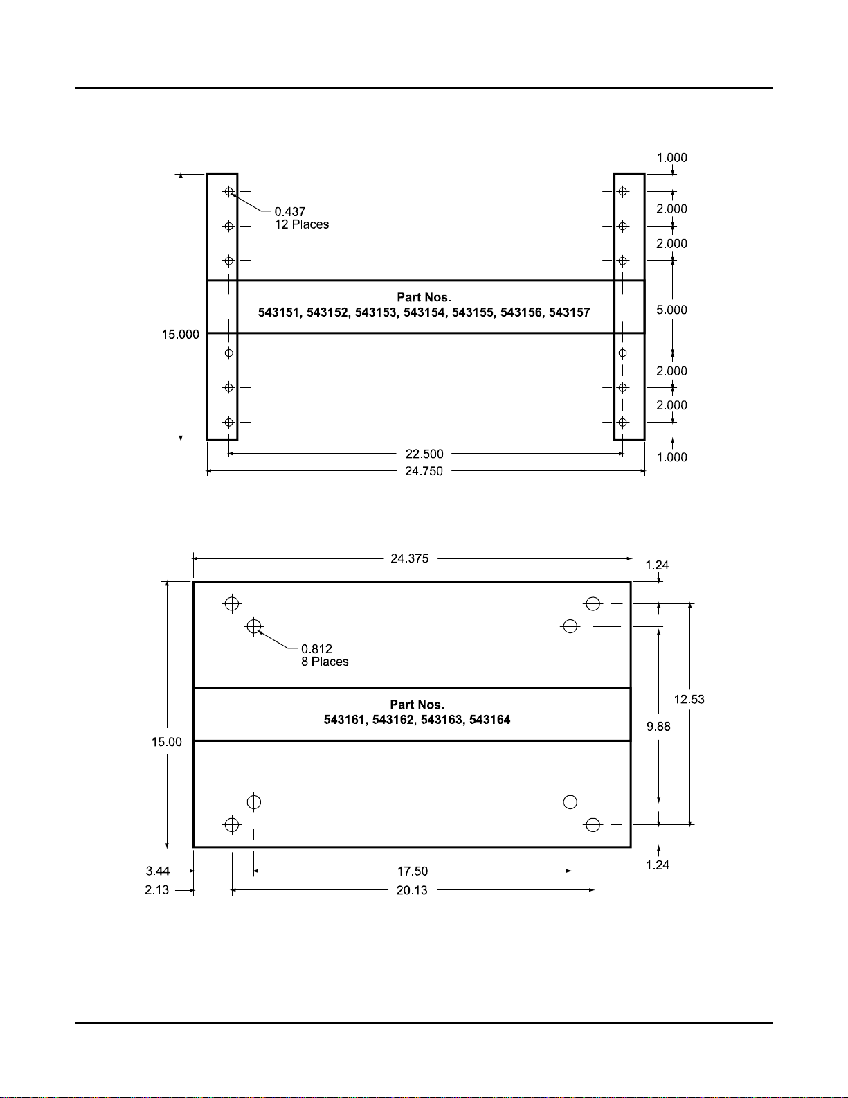
Relay Rack Floor Mounting Dimensions
Refer to Figure 2-1 for relay rack floor mounting dimensions.
Figure 2-1 (cont’d on next page)
Relay Rack Floor Mounting Dimensions
Page 4 Chapter 2. Installing the System
This document is property of Emerson Network Power, Energy Systems, North America, Inc. and contains confidential and proprietary information owned by Emerson Network Power, Energy
Systems, North America, Inc. Any copying, use, or disclosure of it without the written permission of Emerson Network Power, Energy Systems, North America, Inc. is strictly prohibited.
Page 13
Installation Instructions IM581127000
Spec. No. 581127000 (Model 710NPBA) Issue AB, March 22, 2012
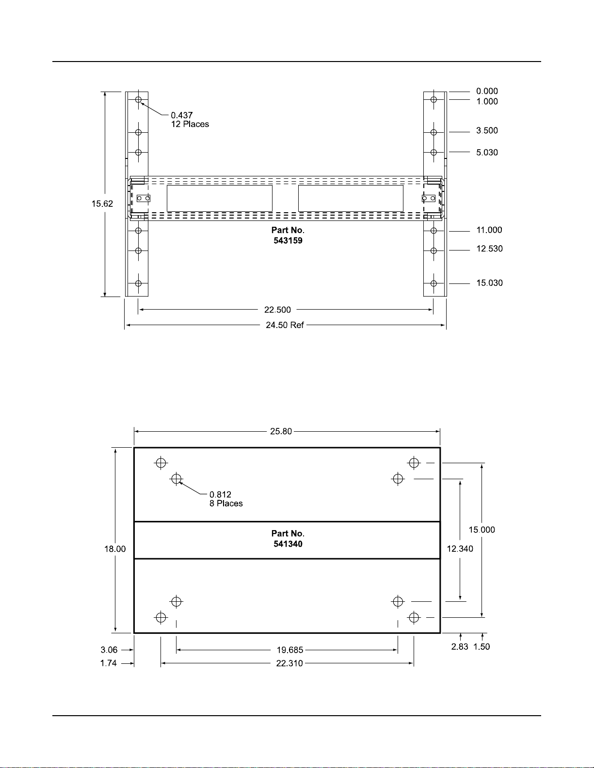
Figure 2-1 (cont’d from previous page, cont’d on next page)
Relay Rack Floor Mounting Dimensions
Chapter 2. Installing the System Page 5
This document is property of Emerson Network Power, Energy Systems, North America, Inc. and contains confidential and proprietary information owned by Emerson Network Power, Energy
Systems, North America, Inc. Any copying, use, or disclosure of it without the written permission of Emerson Network Power, Energy Systems, North America, Inc. is strictly prohibited.
Page 14
IM581127000 Installation Instructions
Issue AB, March 22, 2012 Spec. No. 581127000 (Model 710NPBA)
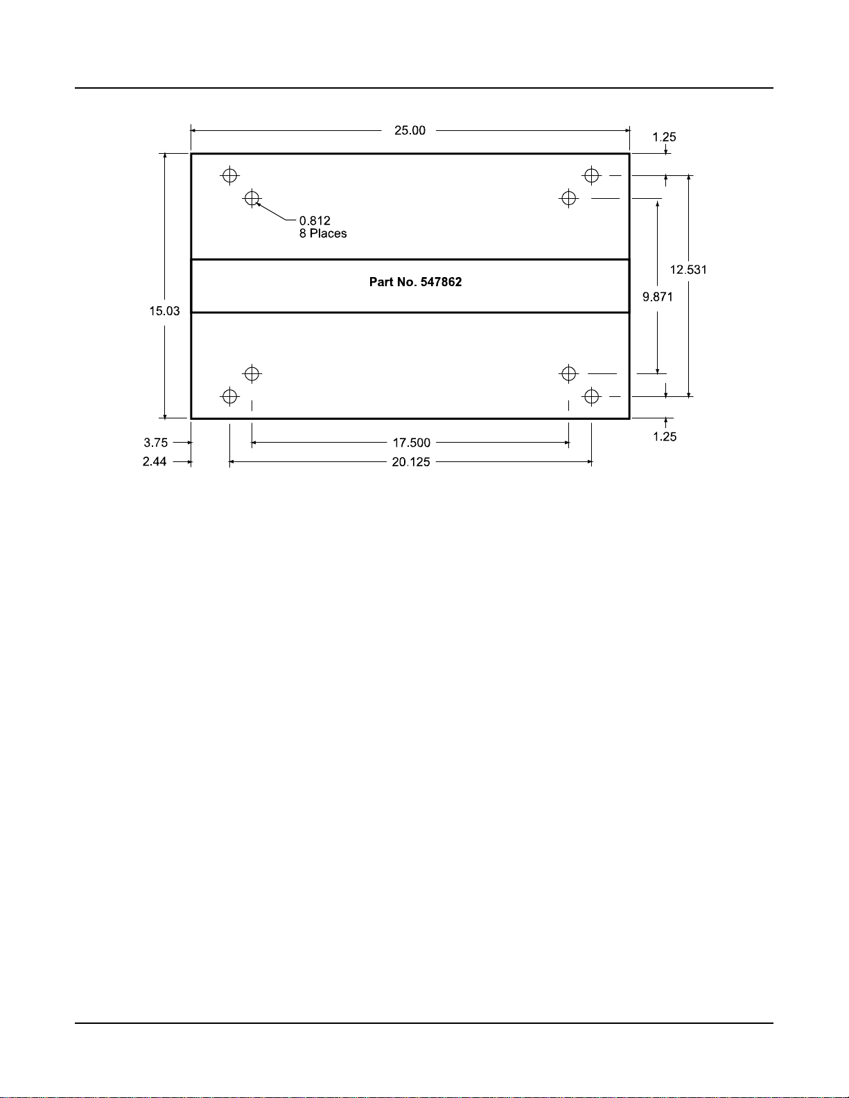
Figure 2-1 (cont’d from previous page)
Relay Rack Floor Mounting Dimensions
Page 6 Chapter 2. Installing the System
This document is property of Emerson Network Power, Energy Systems, North America, Inc. and contains confidential and proprietary information owned by Emerson Network Power, Energy
Systems, North America, Inc. Any copying, use, or disclosure of it without the written permission of Emerson Network Power, Energy Systems, North America, Inc. is strictly prohibited.
Page 15

Installation Instructions IM581127000
Spec. No. 581127000 (Model 710NPBA) Issue AB, March 22, 2012
MOUNTING SYSTEM COMPONENTS IN AN EQUIPMENT RACK
Note: If the power system was ordered in a relay rack, these procedures have been
performed at the factory.
This power system is designed to mount in a standard 23” relay rack having 1” or 1-3/4”
multiple drillings. Refer to System Application Guide SAG581127000 for overall
dimensions and a list of available relay racks.
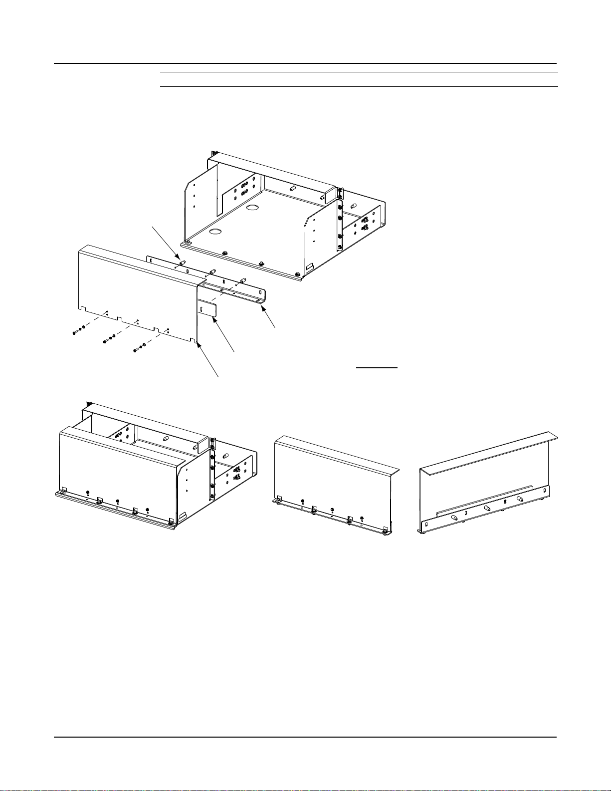
Mounting the Distribution Cabinet with Module Mounting Assembly
Note: The distribution cabinet is factory connected to the module mounting assembly.
The distribution cabinet with module mounting assembly is mounted as a
complete assembly.
The distribution cabinet with module mounting assembly must be the top-most
component in the rack. Perform the following steps to mount the distribution cabinet with
module mounting assembly.
Danger: The relay rack must be securely anchored to the floor before the
distribution cabinet with module mounting assembly is installed.
The distribution cabinet with module mounting assembly is heavy. Use a
hoist, battery lift, or other appropriate lifting device to raise and support
the assembly during the installation. Take appropriate precautions to
avoid injury.
Procedure
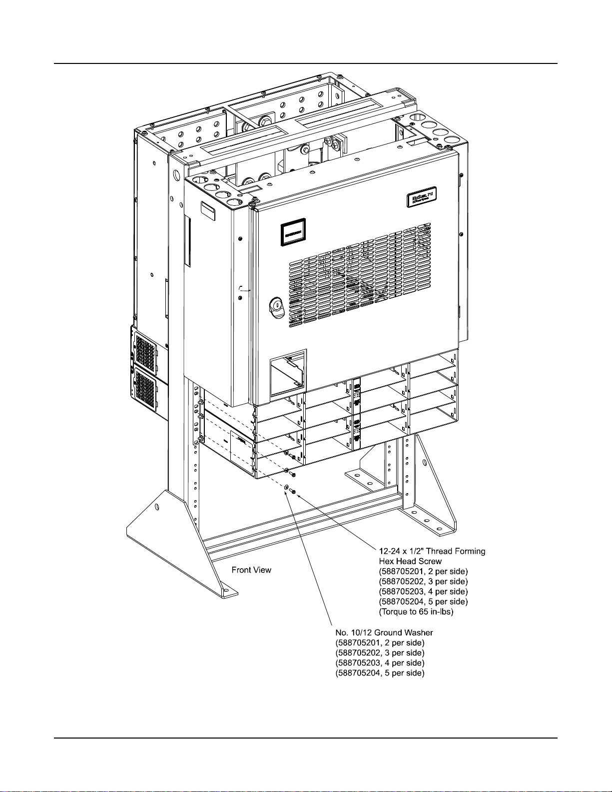
1) Remove the distribution cabinet with module mounting assembly from its
shipping brackets. Position the assembly in the equipment rack. Note that part
of the AC wireways will have to be temporarily removed from the distribution
cabinet to access the mounting hardware.
Note: Install the ground washers so the teeth dig into the paint on the mounting
angles. Torque all screws to 65 in-lbs.
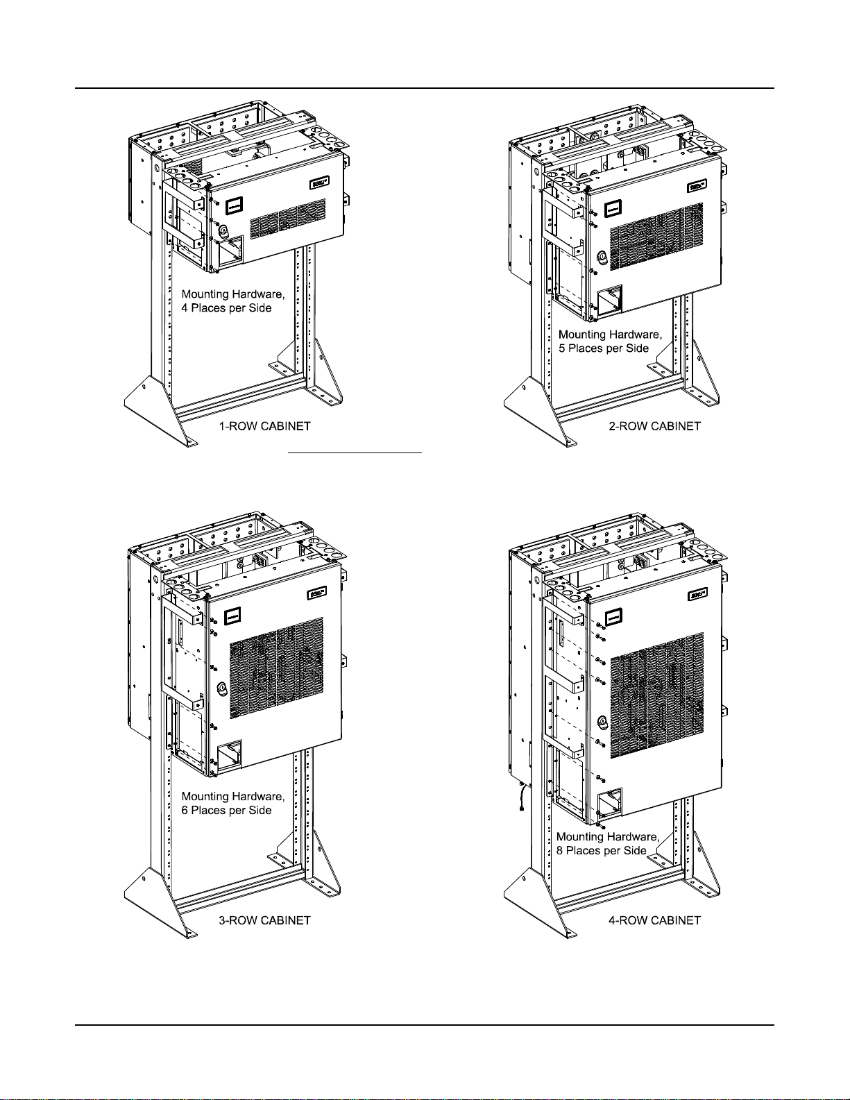
2) Mount the distribution cabinet to the relay rack using the following hardware.
Refer to Figure 2-2.
a) 1-Row Cabinet: Install (8) 12-24 x 1/2" hex head thread-forming screws
(P/N 218710500) and (8) No. 12 ground washers (P/N 215640600).
b) 2-Row Cabinet: Install (10) 12-24 x 1/2" hex head thread-forming screws
(P/N 218710500) and (8) No. 12 ground washers (P/N 215640600).
c) 3-Row Cabinet: Install (12) 12-24 x 1/2" hex head thread-forming screws
(P/N 218710500) and (14) No. 12 ground washers (P/N 215640600).
d) 4-Row Cabinet: Install (16) 12-24 x 1/2" hex head thread-forming screws
(P/N 218710500) and (16) No. 12 ground washers (P/N 215640600).
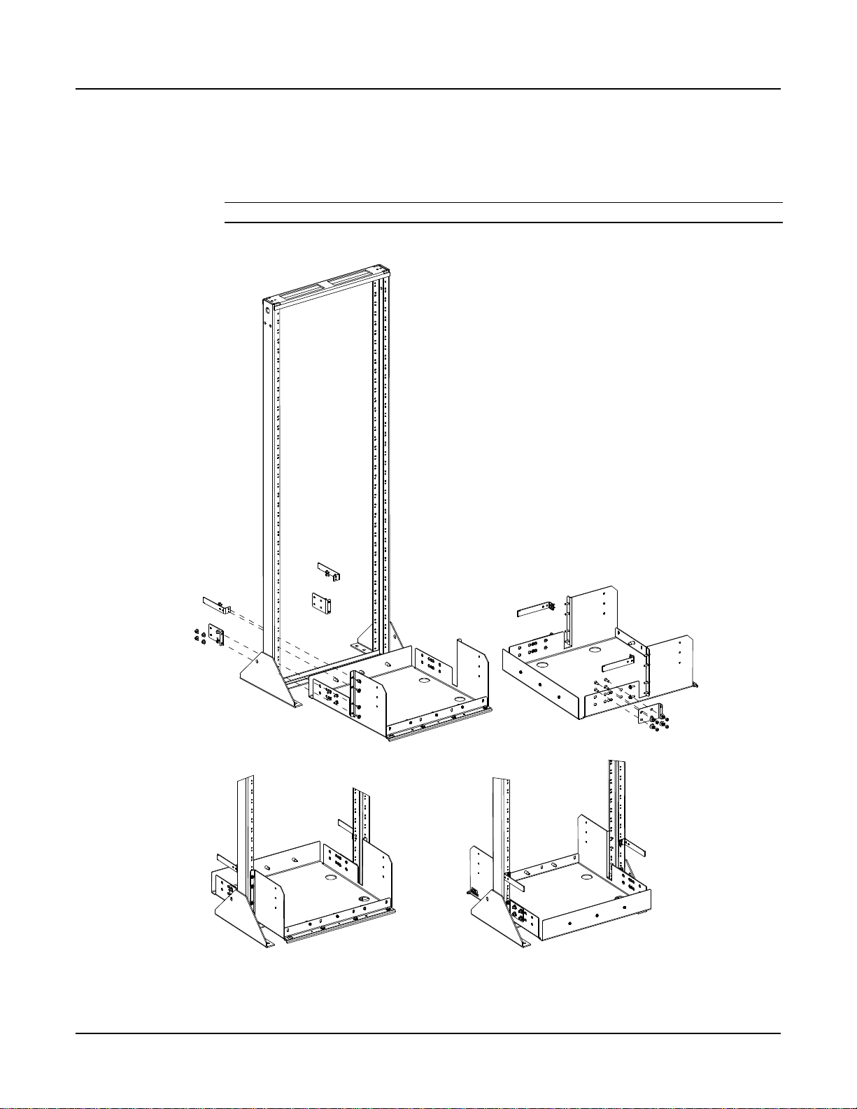
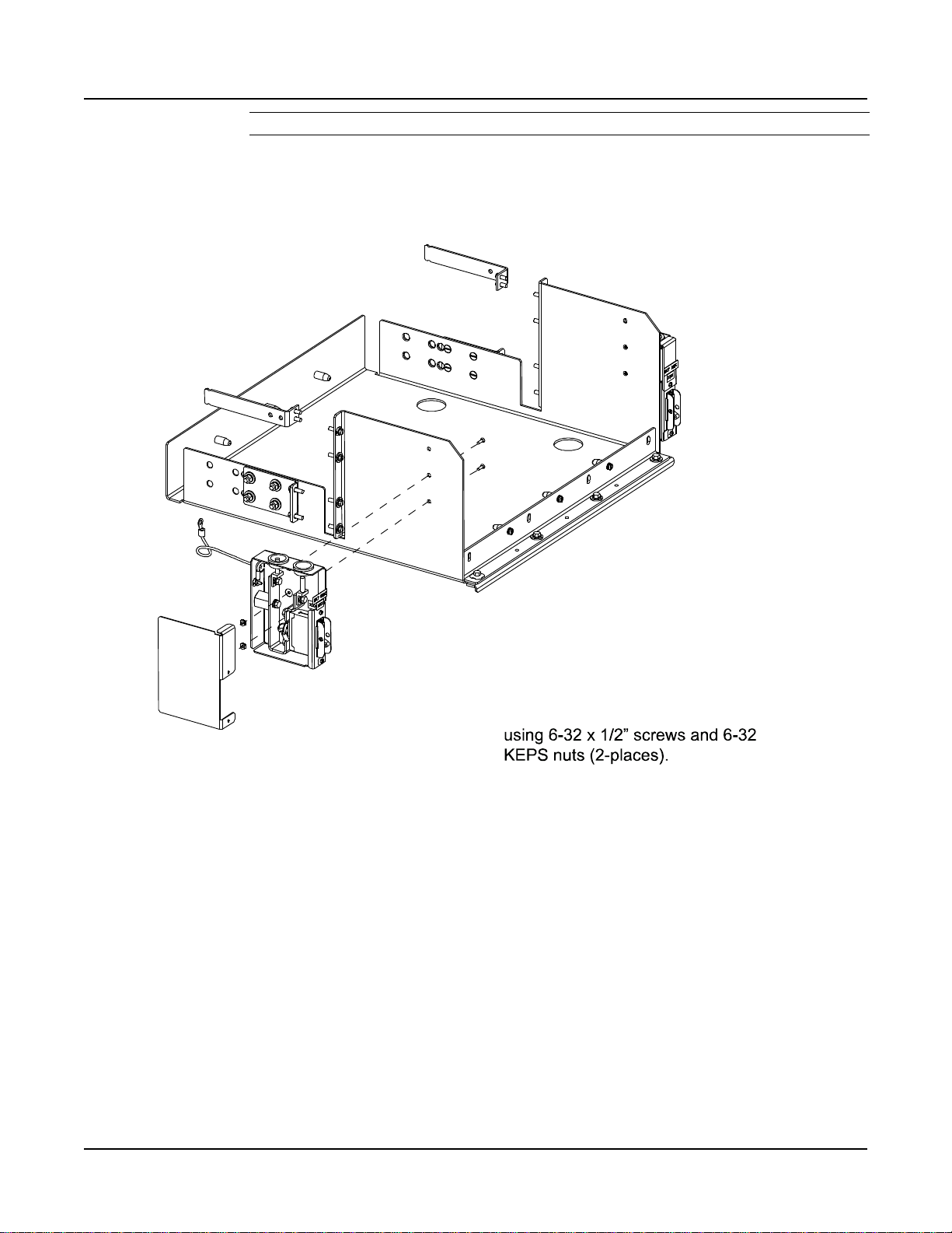
3) Mount the module mounting assembly to the relay rack using hardware as shown
Figure 2-3.
Chapter 2. Installing the System Page 7
This document is property of Emerson Network Power, Energy Systems, North America, Inc. and contains confidential and proprietary information owned by Emerson Network Power, Energy
Systems, North America, Inc. Any copying, use, or disclosure of it without the written permission of Emerson Network Power, Energy Systems, North America, Inc. is strictly prohibited.
Page 16
IM581127000 Installation Instructions
MOUNTING HARDWARE
12-24 X1/2" THREAD FORMING HEX HEAD SCREW
NO. 12 GROUND WASHER
Module Mounting ShelfAssembly not shown for clarity only.
Issue AB, March 22, 2012 Spec. No. 581127000 (Model 710NPBA)
Figure 2-2
Distribution Cabinet Mounting Hardware View
Page 8 Chapter 2. Installing the System
This document is property of Emerson Network Power, Energy Systems, North America, Inc. and contains confidential and proprietary information owned by Emerson Network Power, Energy
Systems, North America, Inc. Any copying, use, or disclosure of it without the written permission of Emerson Network Power, Energy Systems, North America, Inc. is strictly prohibited.
Page 17
Installation Instructions IM581127000
Secure the Module Mounting
Shelf to therelay rack.
Spec. No. 581127000 (Model 710NPBA) Issue AB, March 22, 2012
Figure 2-3
Module Mounting Assembly Mounting Hardware View
Chapter 2. Installing the System Page 9
This document is property of Emerson Network Power, Energy Systems, North America, Inc. and contains confidential and proprietary information owned by Emerson Network Power, Energy
Systems, North America, Inc. Any copying, use, or disclosure of it without the written permission of Emerson Network Power, Energy Systems, North America, Inc. is strictly prohibited.
Page 18
IM581127000 Installation Instructions
Battery Tray
Rear
Angle
Bracket
Rear Angle Bracket
Cabling
Bracket
Front Rear
1. Slide battery tray into relay rack and
secure to relay rack with12-24 x 3/4"
thread forming hexhead screws and
#10/12 ground washers(1 place per
side) or #12flat washers (3 places per
side). (Torque to 70 in-lbs).
2. Secure rear angle brackets (both sides)
to battery traywith 1/4-20 x 3/4” bolts,
1/4” flat washers, 1/4” lockwashers, and
1/4” nuts. (Torque to 84 in-lbs).
3. Secure rear angle brackets (both sides)
to relay rackwith 12-24x 3/4" thread
forming hex head screws and #10/12
ground washers (1 place per bracket)
or #12 flat washers (1 place per bracket).
(Torque to70 in-lbs).
4. Secure cabling brackets (both sides) to
relay rack with 12-24 x1/2" thread forming
hex head screws.(Torque to 70 in-lbs).
Issue AB, March 22, 2012 Spec. No. 581127000 (Model 710NPBA)
Installing a List 93 Battery Tray
Perform the following procedures to install a List 93 Battery Tray.
Danger: The relay rack must be securely anchored to the floor before a battery
tray is installed.
Installing a Battery Tray Procedure
1) To install a List 93 Battery Tray, perform the procedure in Figure 2-4.
Figure 2-4
Installing a List 93 Battery Tray
Page 10 Chapter 2. Installing the System
This document is property of Emerson Network Power, Energy Systems, North America, Inc. and contains confidential and proprietary information owned by Emerson Network Power, Energy
Systems, North America, Inc. Any copying, use, or disclosure of it without the written permission of Emerson Network Power, Energy Systems, North America, Inc. is strictly prohibited.
Page 19
Installation Instructions IM581127000
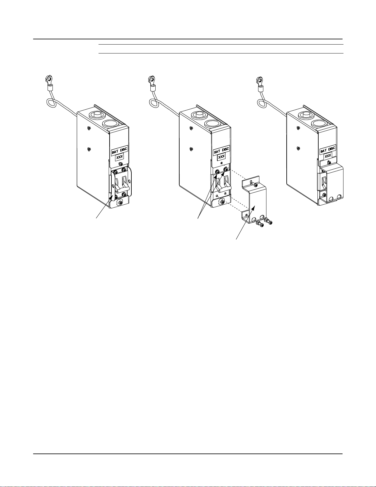
Battery Disconnect
Circuit Breaker Assembly
1. Remove the cover from the battery
disconnect circuit breaker assembly.
2. Secure the battery disconnect circuit
breaker assembly to the battery tray
3. Secure the ground lead under a battery
tray relay rack mounting bolt.
4. After wiring to the battery disconnect
circuit breaker, replace the cover.
5. Repeat for the other side of the battery
tray.
Spec. No. 581127000 (Model 710NPBA) Issue AB, March 22, 2012
Installing Optional Battery Disconnect Circuit Breakers Procedure
1) To install optional battery disconnect circuit breakers onto the List 93 Battery
Tray, perform the procedure in Figure 2-5.
2) Battery tray wiring is shown in “Installing and Connecting Batteries in List 93
Battery Tray” in Chapter 4. Making Electrical Connections.
Installing Optional Battery Disconnect Circuit Breakers onto a List 93 Battery Tray
Figure 2-5
Chapter 2. Installing the System Page 11
This document is property of Emerson Network Power, Energy Systems, North America, Inc. and contains confidential and proprietary information owned by Emerson Network Power, Energy
Systems, North America, Inc. Any copying, use, or disclosure of it without the written permission of Emerson Network Power, Energy Systems, North America, Inc. is strictly prohibited.
Page 20
IM581127000 Installation Instructions
Assembled View
Kit Battery Cover
Assembled to Existing
Front Battery Bracket
Rear View
Kit Battery Cover
Assembled to Existing
Front Battery Bracket
Front View
Use kit supplied hardware.
Procedure
1. Install batteries.
2. Install kit battery cover to
existing front battery bracket.
3. Install kit battery cover with existing
front battery bracket to battery shelf.
Kit supplied cover.
Kit supplied spacer bar.
Existing front battery bracket.
Use existing
battery spacers.
Issue AB, March 22, 2012 Spec. No. 581127000 (Model 710NPBA)
Installing Optional Front Battery Cover Procedure
1) To install an optional front battery cover onto a List 93 Battery Tray, perform the
procedure in Figure 2-6. Note that batteries must be installed first, as described
in “Installing and Connecting Batteries in List 93 Battery Tray” in Chapter 4.
Making Electrical Connections.
Installing Optional Front Battery Cover onto a List 93 Battery Tray
Figure 2-6
Page 12 Chapter 2. Installing the System
This document is property of Emerson Network Power, Energy Systems, North America, Inc. and contains confidential and proprietary information owned by Emerson Network Power, Energy
Systems, North America, Inc. Any copying, use, or disclosure of it without the written permission of Emerson Network Power, Energy Systems, North America, Inc. is strictly prohibited.
Page 21
Installation Instructions IM581127000
1. Remove this bracket. 2. Replace this hardware after
removing existing bracket.
3. Install Circuit Breaker
Guard Bracket using
existing hardware.
Installed View
Spec. No. 581127000 (Model 710NPBA) Issue AB, March 22, 2012
Installing Optional Circuit Breaker Guard Procedure
1) To install an optional circuit breaker guard onto a battery disconnect circuit
breaker, perform the procedure in Figure 2-7.
Figure 2-7
Installing Optional Circuit Breaker Guard
Chapter 2. Installing the System Page 13
This document is property of Emerson Network Power, Energy Systems, North America, Inc. and contains confidential and proprietary information owned by Emerson Network Power, Energy
Systems, North America, Inc. Any copying, use, or disclosure of it without the written permission of Emerson Network Power, Energy Systems, North America, Inc. is strictly prohibited.
Page 22
IM581127000 Installation Instructions
Qty.
Part No.
Description
1
534447
Busbar
1
534448
Busbar
8
214110100
Flat Washer, 1/4”
4
214112100
Flat Washer, 3/8”
8
215111100
Lock Washer, 1/4”
4
215111300
Lock Washer, 3/8”
4
227640400
Hex Head Bolt, 1/4-20 x 3/4”
(not used)
2
227646600
Hex Head Bolt, 3/8-16 x 1”
8
228557100
Nut, 1/4-20
2
228567100
Nut, 3/8-16
Qty.
Part No.
Description
1
514676
Busbar
1
514678
Busbar
12
214110100
Flat Washer, 1/4”
4
214112100
Flat Washer, 3/8”
12
215111100
Lock Washer, 1/4”
4
215111300
Lock Washer, 3/8”
6
227640400
Hex Head Bolt, 1/4-20 x 3/4”
(not used)
2
227646600
Hex Head Bolt, 3/8-16 x 1”
12
228557100
Nut, 1/4-20
2
228567100
Nut, 3/8-16
Issue AB, March 22, 2012 Spec. No. 581127000 (Model 710NPBA)
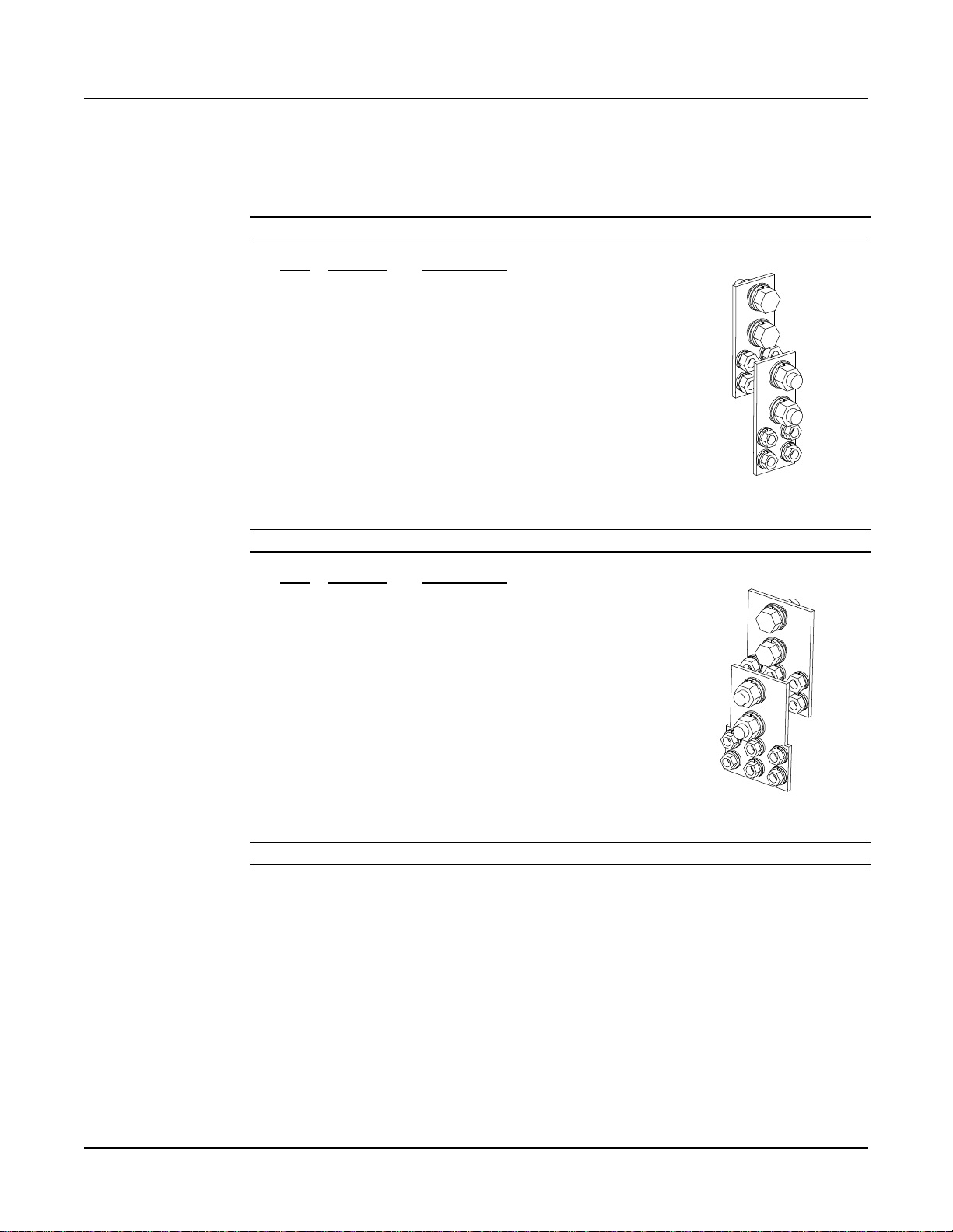
INSTALLING OPTIONAL LUG ADAPTER BUSBAR KITS, PART NOS. 534449 AND 514714
These kits provide lug adapter busbars plus hardware for use with 2-pole and 3-pole
circuit breakers.
Contents of Kit P/N 534449 (for 2-pole circuit breakers)
Contents of Kit P/N 514714 (for 3-pole circuit breakers)
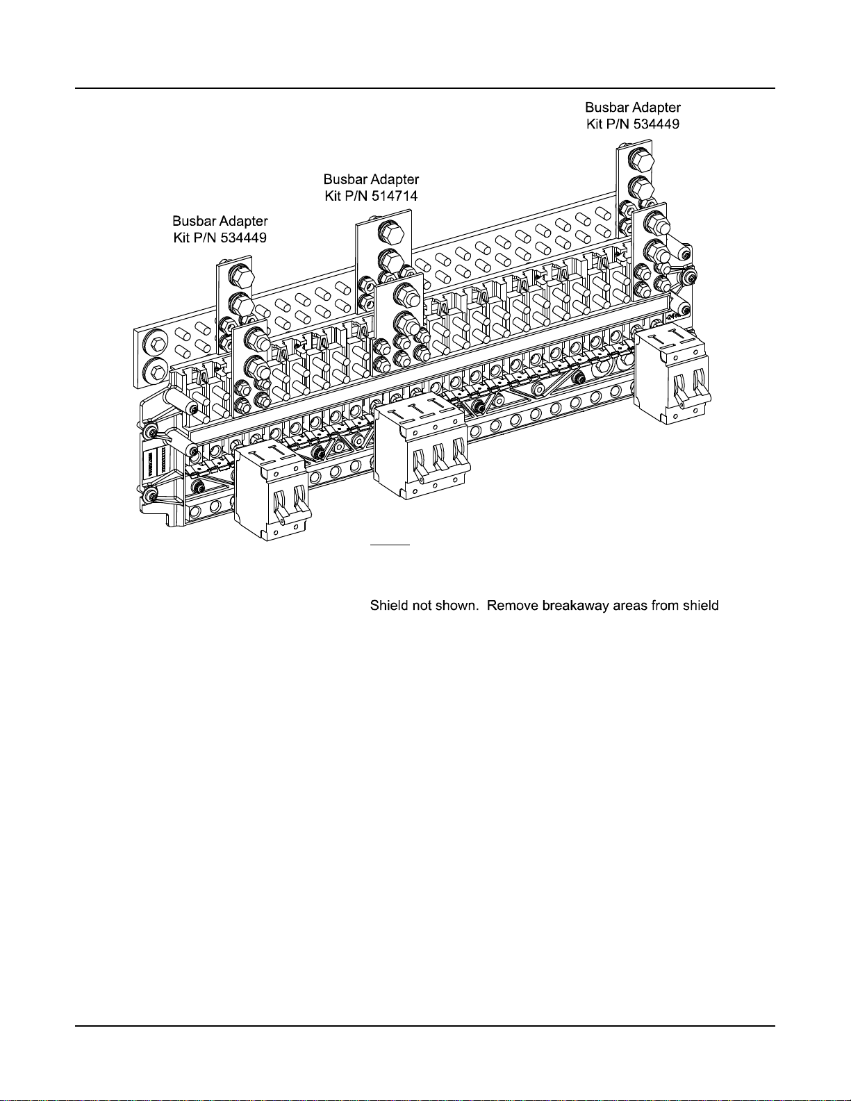
Procedure
Perform the following steps to install the lug adapter busbars. Refer to Figure 2-8 as the
procedure is performed. Note also the restrictions on location in Figure 2-8.
1) Open the distribution cabinet’s front door by turning the latch in the
counterclockwise position.
2) Install the lug adapter busbars as shown in Figure 2-8. Apply anti-oxidizing
compound to busbar mating surfaces before assembling. Recommended torque
is 72 in-lbs using the supplied 1/4” bolts and hardware.
Page 14 Chapter 2. Installing the System
This document is property of Emerson Network Power, Energy Systems, North America, Inc. and contains confidential and proprietary information owned by Emerson Network Power, Energy
Systems, North America, Inc. Any copying, use, or disclosure of it without the written permission of Emerson Network Power, Energy Systems, North America, Inc. is strictly prohibited.
3) Orient the load lug hardware as shown in Figure 2-8. Recommended torque is
300 in-lbs using the supplied 3/8” bolts and hardware.
4) Close the distribution cabinet’s front door. Turn the latch clockwise to secure the
door.
Page 23
Installation Instructions IM581127000
Notes:
Orient busbars as shown.
as required. Breakaways are only provided forpositions
1-8, 9-12, and 23-24. This restricts 2 and 3-pole breaker
adapter kits to be located in thesepositions only.
Circuit breaker locations for reference only.
Spec. No. 581127000 (Model 710NPBA) Issue AB, March 22, 2012
Figure 2-8
Installing Lug Adapter Busbar Kits
Chapter 2. Installing the System Page 15
This document is property of Emerson Network Power, Energy Systems, North America, Inc. and contains confidential and proprietary information owned by Emerson Network Power, Energy
Systems, North America, Inc. Any copying, use, or disclosure of it without the written permission of Emerson Network Power, Energy Systems, North America, Inc. is strictly prohibited.
Page 24

IM581127000 Installation Instructions
Issue AB, March 22, 2012 Spec. No. 581127000 (Model 710NPBA)
INSTALLING CIRCUIT BREAKERS AND FUSES
Circuit breakers and/or fuses may have been factory installed for you.
If so, verify their positions and sizes.
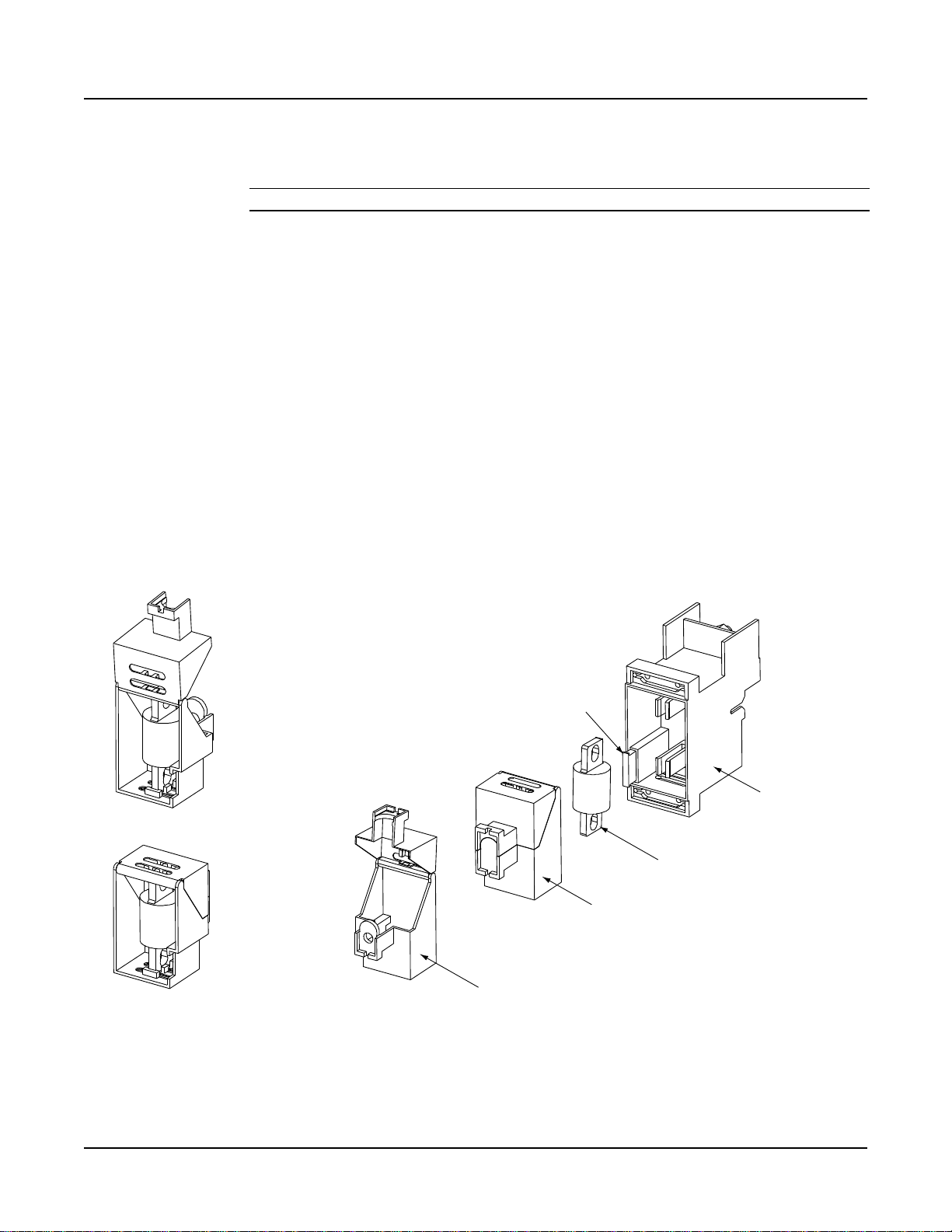
Installing Bullet Nose Type Fuseholders and TPS/TLS Fuses
Caution: A circuit breaker or fuse with a rating of 100A or greater SHALL HAVE an
empty mounting position between it and any other overcurrent protective
device.
Refer to the following procedure and install bullet nose type fuseholders and
appropriately sized TPS/TLS fuses into the proper mounting positions in the distribution
cabinet.
Procedure
Note: Refer to Figure 2-9 as this procedure is performed.
1) Open the distribution cabinet’s front door by turning the latch in the
counterclockwise position.
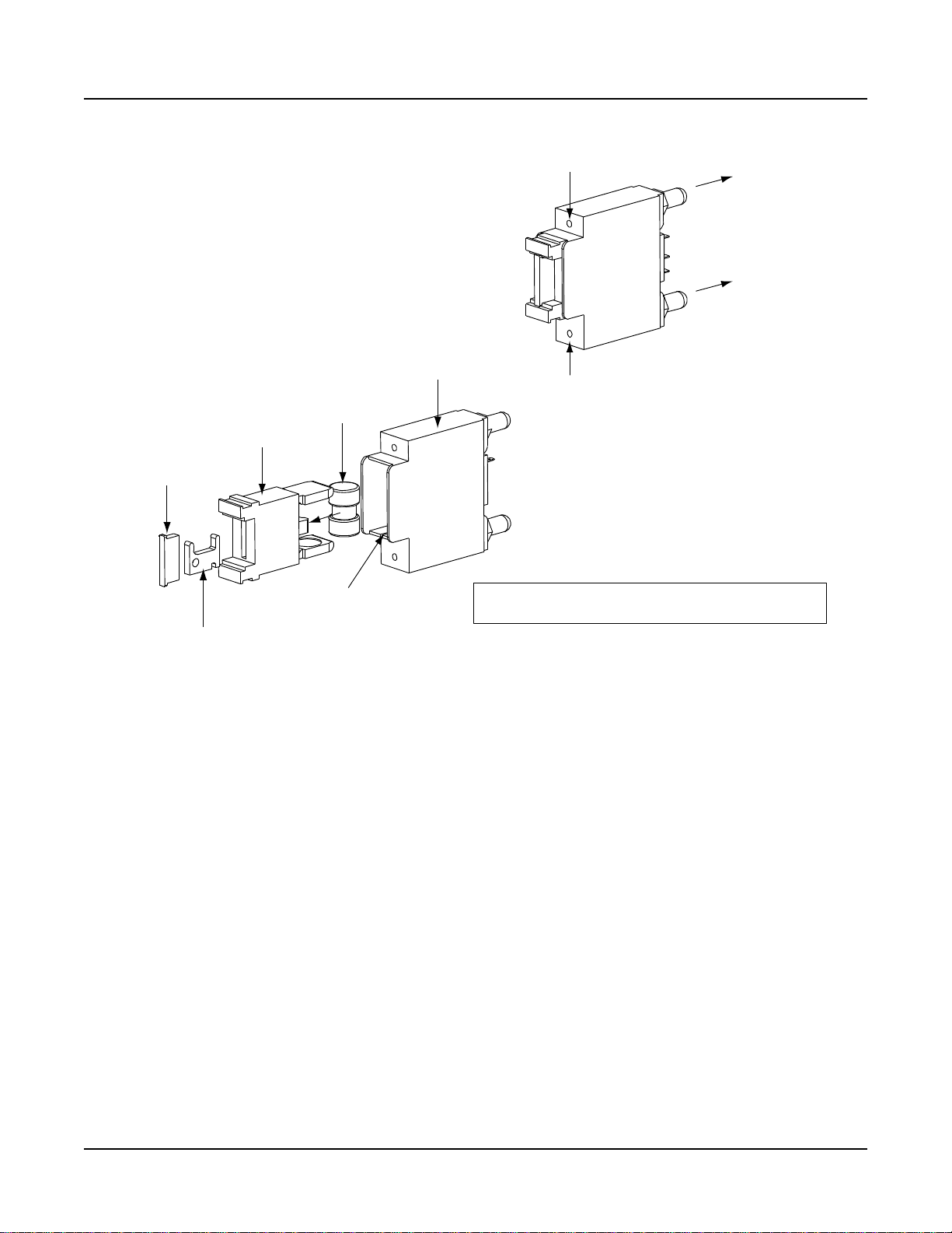
2) Orient the fuseholder as shown in Figure 2-9. Insert the terminals on the rear of
the fuseholder into their corresponding sockets on the distribution panel. Ensure
the alarm contact on the back of the fuseholder makes contact with the alarm
terminal on the mounting circuit card. Push fuseholder in firmly until fully seated
in the distribution panel.
3) When all fuseholders are installed, install an appropriately sized TPS/TLS fuse in
each. To do this, remove the fuse carrier from the mounted fuseholder body by
pulling it straight out. Slide the fuse in place between the contacts of the fuse
carrier. When done, push the fuse carrier back into the fuseholder body. Note
that a polarizing key on the bottom of the carrier prevents the carrier from being
inserted upside down.
4) Verify that an 18/100 ampere alarm fuse is present in each fuseholder and that a
plastic safety cover is installed on this fuse.
5) Record all fuse sizes on the label provided on the shield.
6) Close the distribution cabinet's front door. Turn the latch clockwise to secure the
door.
Page 16 Chapter 2. Installing the System
This document is property of Emerson Network Power, Energy Systems, North America, Inc. and contains confidential and proprietary information owned by Emerson Network Power, Energy
Systems, North America, Inc. Any copying, use, or disclosure of it without the written permission of Emerson Network Power, Energy Systems, North America, Inc. is strictly prohibited.
Page 25
Installation Instructions IM581127000
Fuseholder Assembly
Longer Side
to the Bottom
Shorter Side
to the Top
Fuse Carrier
Fuseholder Body
TPS/TLS Fuse
Polarizing Keyway
Matches Key on
Bottom of Fuse Carrier
Fuseholder Assembly
Exploded View
Fuseholder Assembly (P/N 117201)includes
body &carrier,alarm fuse,and alarmfuse safety cover.
Insert these terminals
into corresponding sockets
on distribution panel.
GMT-X
Safety Fuse Cover
(Replacement
P/N 248898700)
GMT-18/100A
Alarm Fuse
(Replacement
P/N 248610301)
Spec. No. 581127000 (Model 710NPBA) Issue AB, March 22, 2012
Chapter 2. Installing the System Page 17
This document is property of Emerson Network Power, Energy Systems, North America, Inc. and contains confidential and proprietary information owned by Emerson Network Power, Energy
Systems, North America, Inc. Any copying, use, or disclosure of it without the written permission of Emerson Network Power, Energy Systems, North America, Inc. is strictly prohibited.
Installing a Bullet Nose Type Fuseholder and TPS/TLS Fuse
Figure 2-9
Page 26
IM581127000 Installation Instructions
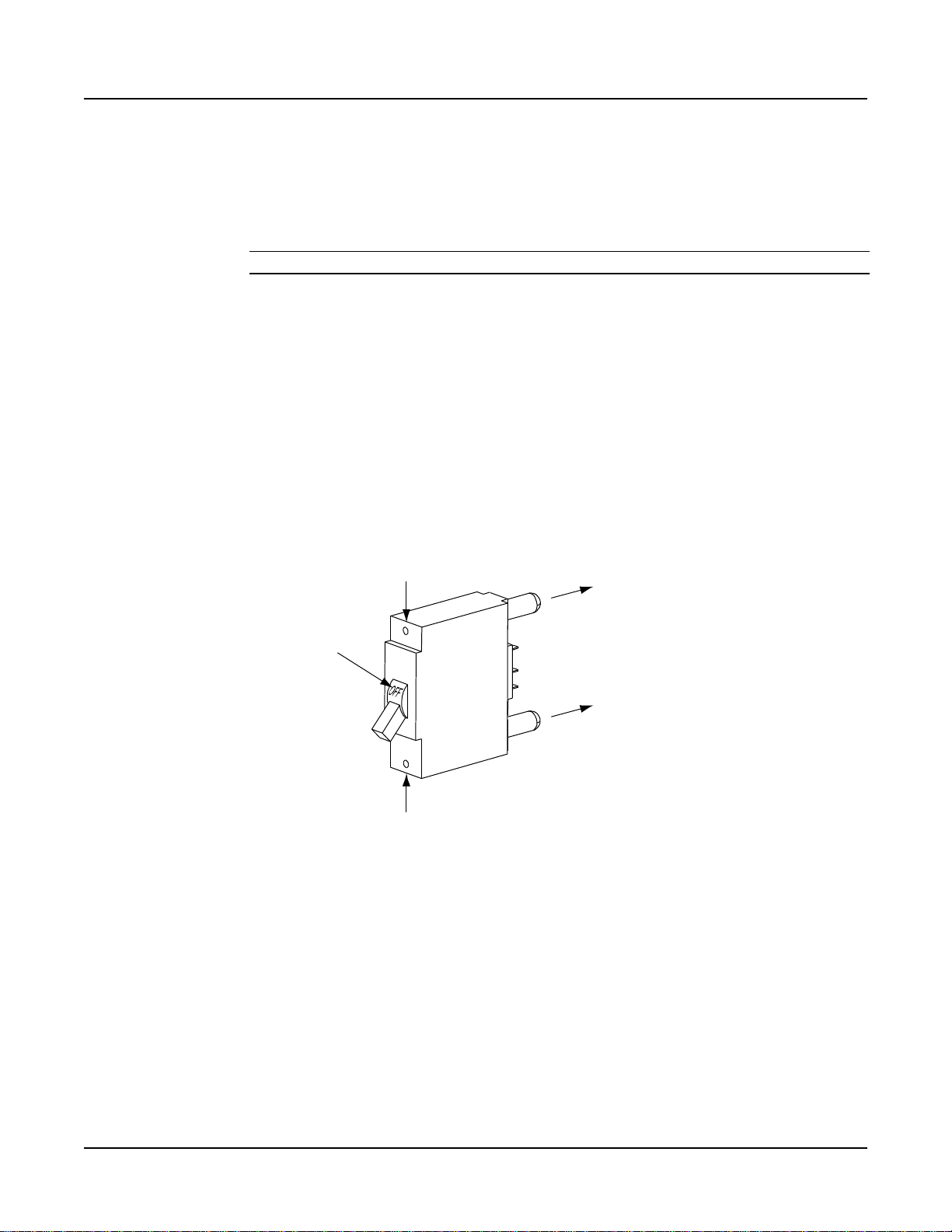
Insert these terminals
into corresponding sockets
on distribution panel.
Longer Side
to the Bottom
Shorter Side
to the Top
Lettering on
handle must be
right side up.
Turn off
before installing.
Issue AB, March 22, 2012 Spec. No. 581127000 (Model 710NPBA)
Installing Bullet Nose Type Circuit Breakers
Caution: A circuit breaker or fuse with a rating of 100A or greater SHALL HAVE an
empty mounting position between it and any other overcurrent protective
device.
Refer to the following procedure and install appropriately sized bullet nose type circuit
breakers into the proper mounting positions in the distribution cabinet.
Procedure
Note: Refer to Figure 2-10 as this procedure is performed.
1) Open the distribution cabinet’s front door by turning the latch in the
counterclockwise position.
2) Ensure that the circuit breaker is in the OFF position and is of the correct rating.
Orient the circuit breaker as shown in Figure 2-10. Insert the terminals on the
rear of the circuit breaker into their corresponding sockets on the distribution
panel. Ensure the alarm contact on the back of the circuit breaker makes contact
with the alarm terminal on the mounting circuit card. Push distribution device in
firmly until fully seated in the distribution panel.
3) Record all circuit breaker sizes on the label provided on the shield.
4) Close the distribution cabinet's front door. Turn the latch clockwise to secure the
door.
Page 18 Chapter 2. Installing the System
This document is property of Emerson Network Power, Energy Systems, North America, Inc. and contains confidential and proprietary information owned by Emerson Network Power, Energy
Systems, North America, Inc. Any copying, use, or disclosure of it without the written permission of Emerson Network Power, Energy Systems, North America, Inc. is strictly prohibited.
Figure 2-10
Installing a Bullet Nose Type Circuit Breaker
Page 27

Installation Instructions IM581127000
Spec. No. 581127000 (Model 710NPBA) Issue AB, March 22, 2012
Installing an Optional Bullet Nose Type 6-Position GMT Distribution Fuse Block
Note: Refer to Figure 2-11 as this procedure is performed.
Procedure
1) Open the distribution cabinet’s front door by turning the latch in the
counterclockwise position.
2) Follow the steps in Figure 2-11.
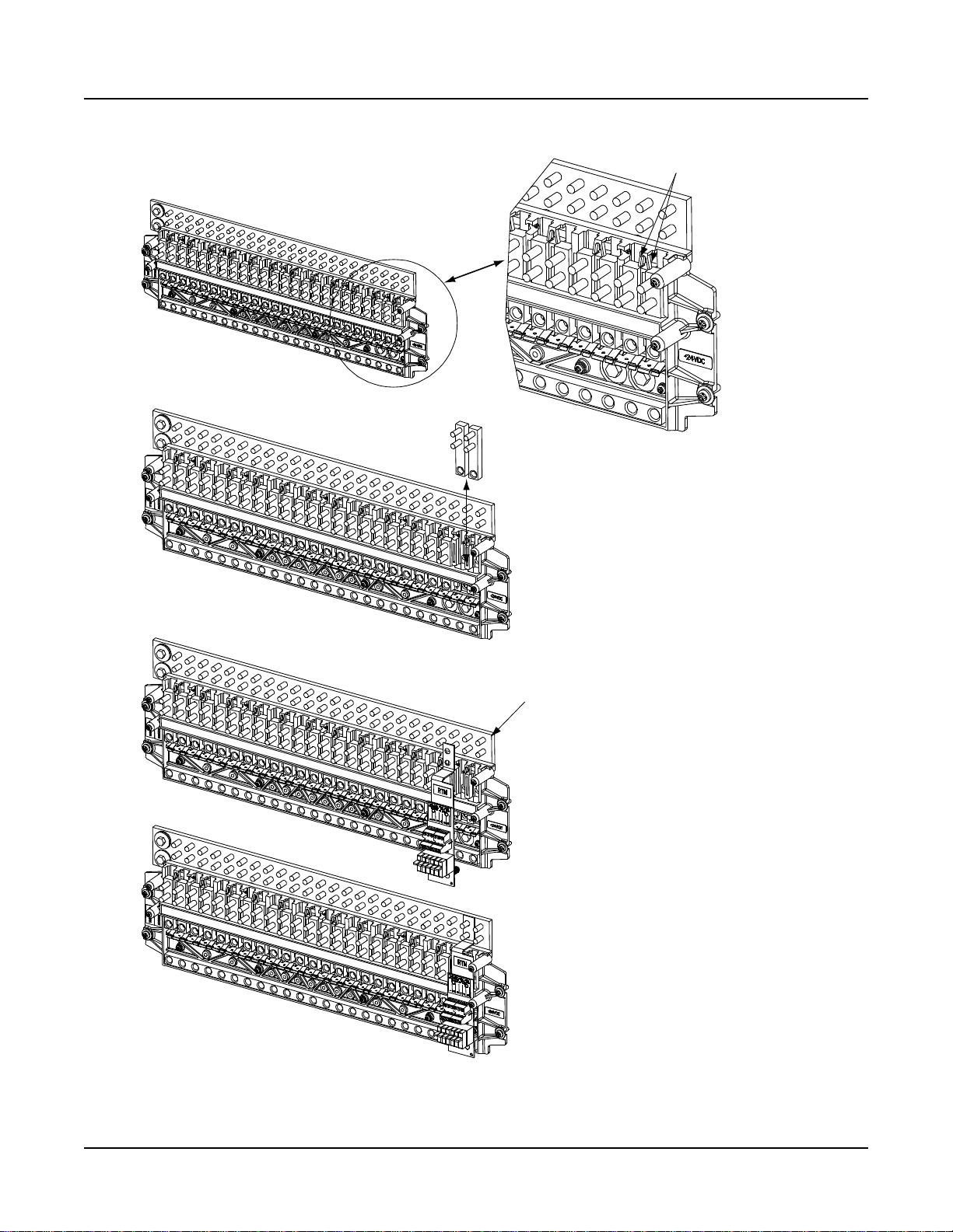
3) Install an appropriately sized GMT fuse in each fuse mounting position on the
GMT Distribution Fuse Block as required. If dummy fuses are installed, first
remove the dummy fuse.
a) Verify that dummy fuses are installed in all unused fuse positions on the
GMT distribution fuse block.
b) Verify that a plastic safety cover is installed on all GMT fuses on the GMT
distribution fuse block.
4) Record all fuse sizes (installed on the GMT distribution fuse block) on the label
provided on the shield.
5) Close the distribution cabinet's front door. Turn the latch clockwise to secure the
door.
Chapter 2. Installing the System Page 19
This document is property of Emerson Network Power, Energy Systems, North America, Inc. and contains confidential and proprietary information owned by Emerson Network Power, Energy
Systems, North America, Inc. Any copying, use, or disclosure of it without the written permission of Emerson Network Power, Energy Systems, North America, Inc. is strictly prohibited.
Page 28
IM581127000 Installation Instructions
Press in tabs to release
lug terminalbusbars for
positions to be occupied
by GMTFuse Block.
Remove twolug terminal busbars
for positions to be occupied
by GMTFuse Block.
Plug inGMT Fuse Block and secure
at twolocations on the RTN bar.
Torque to 72 in-lbs.
RTN Bar
GMT Fuse Block InstalledView
1.
2.
3.
Issue AB, March 22, 2012 Spec. No. 581127000 (Model 710NPBA)
Figure 2-11
Installing an Optional Bullet Nose Type 6-Position GMT Distribution Fuse Block
Page 20 Chapter 2. Installing the System
This document is property of Emerson Network Power, Energy Systems, North America, Inc. and contains confidential and proprietary information owned by Emerson Network Power, Energy
Systems, North America, Inc. Any copying, use, or disclosure of it without the written permission of Emerson Network Power, Energy Systems, North America, Inc. is strictly prohibited.
Page 29
Installation Instructions IM581127000
Spec. No. 581127000 (Model 710NPBA) Issue AB, March 22, 2012
Installing TPH Fuses
Refer to the following procedure and install appropriately sized TPH fuses into the proper
fuseholders in the distribution cabinet.
Procedure
Note: Refer to Figure 2-12 as this procedure is performed.
1) Open the distribution cabinet’s front door by turning the latch in the
counterclockwise position.
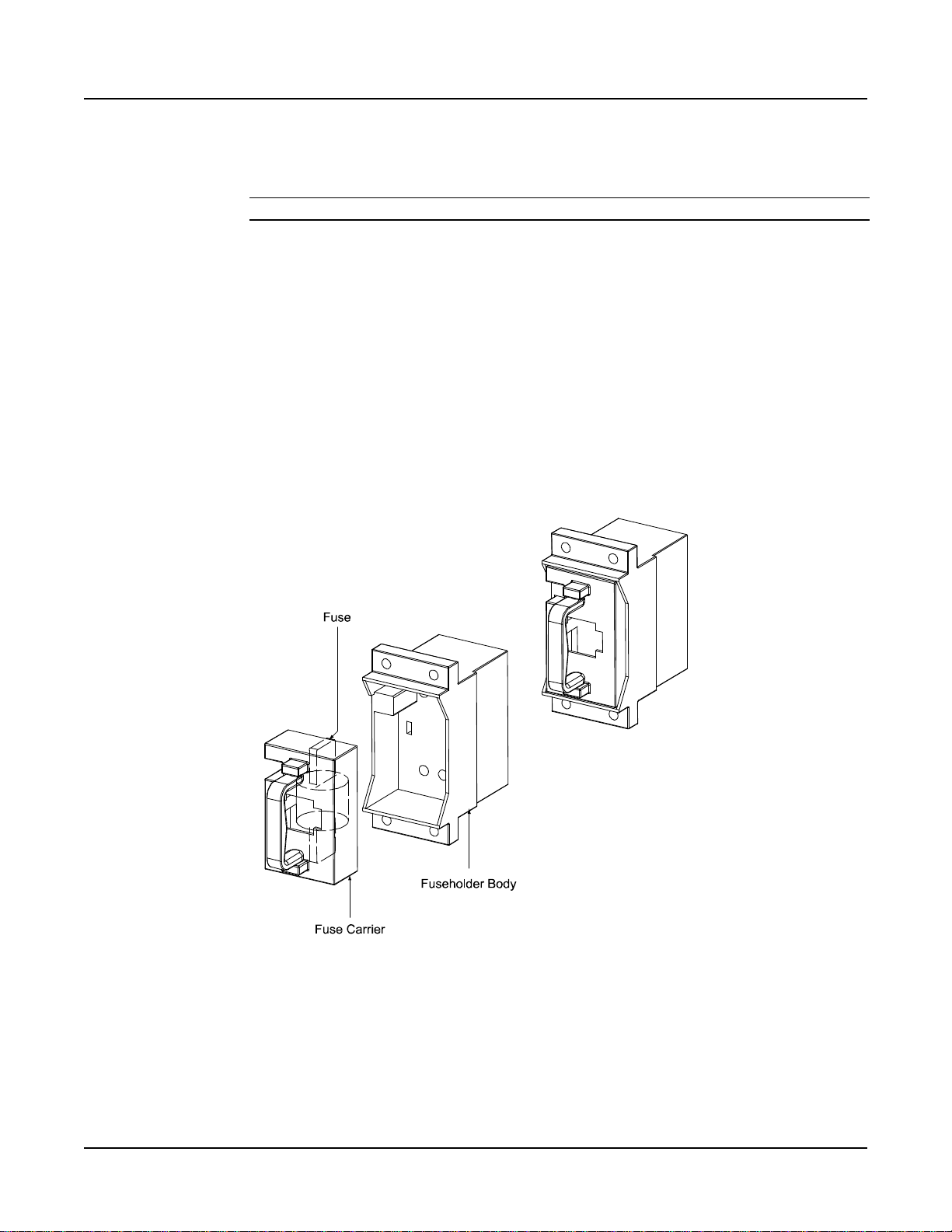
2) Remove the TPH fuse carrier from the mounted fuseholder body by grasping its
handle and firmly pulling it straight out. Install the TPH fuse into the fuse carrier.
When done, push the fuse carrier securely back into the mounted fuseholder
body.
3) Verify that a 1/4 ampere alarm fuse is installed in the GMT-type fuseholder
located adjacent to the TPH fuseholder and that a plastic safety cover is install
on this fuse.
4) Record all fuse sizes on the cards provided within the fuseholders.
5) Close the distribution cabinet's front door. Turn the latch clockwise to secure the
door.
Figure 2-12
Installing a TPH Fuse
Chapter 2. Installing the System Page 21
This document is property of Emerson Network Power, Energy Systems, North America, Inc. and contains confidential and proprietary information owned by Emerson Network Power, Energy
Systems, North America, Inc. Any copying, use, or disclosure of it without the written permission of Emerson Network Power, Energy Systems, North America, Inc. is strictly prohibited.
Page 30
IM581127000 Installation Instructions
Fuse Case
Open FuseCase View
TPL Fuse
Fuse Installedin
Open FuseCase
(rear view)
Fuse Installedin
Closed Fuse Case
(rear view)
Fuseblock
(P/N 516241)
GMT-18/100AAlarm Fuse
(P/N 248610301) and
GMT-X Safety Fuse Cover
(P/N 248898700)
(Both are provided
w/ fuseblock)
Issue AB, March 22, 2012 Spec. No. 581127000 (Model 710NPBA)
Installing TPL-B Fuses
Refer to the following procedure and install appropriately sized TPL-B fuses into the
proper fuseholders in the distribution cabinet.
Procedure
Note: Refer to Figure 2-13 as this procedure is performed.
1) Open the distribution cabinet’s front door by turning the latch in the
counterclockwise position.
2) Remove the fuse case from the mounted fuse block by grasping its handle and
pulling it straight out.
3) Verify that an 18/100 ampere alarm fuse is present in the GMT-type fuseholder
located on the fuse block and that a plastic safety cover is installed on this fuse.
4) Open the fuse case.
5) Install the TPL fuse into the fuse case.
6) Close the fuse case.
7) Firmly plug the fuse and fuse case into the fuse block.
8) Record all fuse sizes on the cards provided within the fuseholders.
9) Close the distribution cabinet's front door. Turn the latch clockwise to secure the
door.
Page 22 Chapter 2. Installing the System
This document is property of Emerson Network Power, Energy Systems, North America, Inc. and contains confidential and proprietary information owned by Emerson Network Power, Energy
Systems, North America, Inc. Any copying, use, or disclosure of it without the written permission of Emerson Network Power, Energy Systems, North America, Inc. is strictly prohibited.
Figure 2-13
Installing TPL-B Fuses
Page 31

Installation Instructions IM581127000
Spec. No. 581127000 (Model 710NPBA) Issue AB, March 22, 2012
Installing GJ/218 Circuit Breakers
Refer to the following procedure and install appropriately sized GJ/218 circuit breakers
into the proper mounting positions in the distribution cabinet.
Procedure
Note: Refer to Figure 2-14 as this procedure is performed.
1) Locate the appropriate circuit breaker mounting kit ordered with the circuit
breaker. The circuit breaker mounting kit contains installation hardware, an
alarm jumper, a shunt jumper (if applicable), a busbar (for 2- and 3-pole circuit
breakers), and a circuit breaker guard. Refer to SAG581127000 for part
numbers of the circuit breaker mounting kits.
2) Open the distribution cabinet’s front door by turning the latch in the
counterclockwise position.
3) Ensure that the circuit breaker is in the OFF position, and is of the correct rating
and type (electrical trip/mechanical trip or electrical trip only). Apply antioxidizing compound to busbar mating surfaces on the distribution panel and the
circuit breaker. Orient the circuit breaker over its mounting location.
a) Attach the alarm jumper connectors to the back of the circuit breaker, then
plug the other end of the alarm jumper into its corresponding connector.
Wiring diagrams are provided in Figure 2-14 and at the end of this procedure.
b) Shunted Breakers Only: Attach the shunt jumper connectors to the back of
the circuit breaker, then route the jumper through the hole in the distribution
panel. Wiring diagrams are provided in Figure 2-14, Figure 2-15, and Figure
2-16.
Danger: The bolts being installed in the following step may be at system
potential. Use insulated tools.
4) Install the circuit breaker into its mounting position and secure with the provided
hardware. Torque to 60 in-lbs.
5) Install the circuit breaker guard and label (refer to Figure 2-14).
6) 2-Pole and 3-Pole Circuit Breakers Only: Install the mounting kit supplied
busbar as shown in Figure 2-14. Torque to 180 in-lbs.
7) Shunted Breakers Only: Route and connect shunt leads to the SM-DU+ and
Shunt Interface Assembly.
8) Record all circuit breaker sizes on the label provided on the shield.
9) Close the distribution cabinet's front door. Turn the latch clockwise to secure the
door.
Chapter 2. Installing the System Page 23
This document is property of Emerson Network Power, Energy Systems, North America, Inc. and contains confidential and proprietary information owned by Emerson Network Power, Energy
Systems, North America, Inc. Any copying, use, or disclosure of it without the written permission of Emerson Network Power, Energy Systems, North America, Inc. is strictly prohibited.
Page 32

IM581127000 Installation Instructions
1/4" Hardened
Flat Washer
1/4" Belleville
Lock Washer
1/4-20 x 3/4” Bolt
(2 places)
Torque to 60 in-lbs.
OFF
ON
Apply anti-oxidizing compound to busbar mating
surfaces before mounting circuit breakers.
INSTALLING CIRCUITBREAKER GUARD
INSTALLING CIRCUITBREAKER
Alarm jumper connector.
Holes toroute shunt jumper through (if applicable).
ALARM WIRING(BREAKERS W/OUT SHUNTS)
ALARM WIRING (BREAKERS WITH SHUNTS)
Issue AB, March 22, 2012 Spec. No. 581127000 (Model 710NPBA)
Page 24 Chapter 2. Installing the System
This document is property of Emerson Network Power, Energy Systems, North America, Inc. and contains confidential and proprietary information owned by Emerson Network Power, Energy
Systems, North America, Inc. Any copying, use, or disclosure of it without the written permission of Emerson Network Power, Energy Systems, North America, Inc. is strictly prohibited.
Figure 2-14 (cont’d on next page)
Installing a GJ/218 Circuit Breaker (1-Pole)
Page 33

Installation Instructions IM581127000
1/4" Hardened
Flat Washer
1/4" Belleville
Lock Washer
1/4-20 x3/4” Bolt
(4 places)
Torque to 60 in-lbs.
Apply anti-oxidizing compound to busbar mating
surfaces before mounting circuit breakers.
OFF
ON
INSTALLING CIRCUITBREAKER GUARD
INSTALLING CIRCUITBREAKER
Alarm jumper connectors.
Holes toroute shunt jumper through (if applicable).
ALARM WIRING(BREAKERS W/OUT SHUNTS)
ALARM WIRING (BREAKERS WITH SHUNTS)
Busbar
2-pole breaker shown.
3-pole and 4-pole breakers similar.
Spec. No. 581127000 (Model 710NPBA) Issue AB, March 22, 2012
Installing a GJ/218 Circuit Breaker (2-Pole, 3-Pole, 4-Pole)
Chapter 2. Installing the System Page 25
This document is property of Emerson Network Power, Energy Systems, North America, Inc. and contains confidential and proprietary information owned by Emerson Network Power, Energy
Systems, North America, Inc. Any copying, use, or disclosure of it without the written permission of Emerson Network Power, Energy Systems, North America, Inc. is strictly prohibited.
Figure 2-14 (cont’d from previous page)
Page 34

IM581127000 Installation Instructions
List AC Only
Issue AB, March 22, 2012 Spec. No. 581127000 (Model 710NPBA)
Figure 2-15
GJ/218 Circuit Breaker Wiring Diagram (List AC and AD)
Page 26 Chapter 2. Installing the System
This document is property of Emerson Network Power, Energy Systems, North America, Inc. and contains confidential and proprietary information owned by Emerson Network Power, Energy
Systems, North America, Inc. Any copying, use, or disclosure of it without the written permission of Emerson Network Power, Energy Systems, North America, Inc. is strictly prohibited.
Page 35

Installation Instructions IM581127000
List BC Only
Spec. No. 581127000 (Model 710NPBA) Issue AB, March 22, 2012
Figure 2-16
GJ/218 Circuit Breaker Wiring Diagram (List BC and BD)
Chapter 2. Installing the System Page 27
This document is property of Emerson Network Power, Energy Systems, North America, Inc. and contains confidential and proprietary information owned by Emerson Network Power, Energy
Systems, North America, Inc. Any copying, use, or disclosure of it without the written permission of Emerson Network Power, Energy Systems, North America, Inc. is strictly prohibited.
Page 36

IM581127000 Installation Instructions
IB2
(ACU+ Interface Board)
(located on inside sidepanel)
Optional EIB
(ACU+ Extended Interface Board)
(located on inside sidepanel)
Optional SM-DU+ and
Shunt Interface Board
4-Row Cabinet Shown,
Others Similar
(Front Door Removed in
Illustration for Clarity)
ACU+ Controller
Mounting Position
System Interface
Circuit Card
OR
Optional Manual Battery
Disconnect Circuit Card
Optional LVD
Driver Circuit Card
Optional LVD Driver
Lite Circuit Card
Optional Manual Battery
Disconnect Circuit Card
Issue AB, March 22, 2012 Spec. No. 581127000 (Model 710NPBA)
CHAPTER 3. SETTING JUMPERS AND SWITCH OPTIONS
CIRCUIT CARD LOCATIONS
Refer to Figure 3-1.
Figure 3-1
Page 28 Chapter 3. Setting Jumpers and Switch Options
This document is property of Emerson Network Power, Energy Systems, North America, Inc. and contains confidential and proprietary information owned by Emerson Network Power, Energy
Systems, North America, Inc. Any copying, use, or disclosure of it without the written permission of Emerson Network Power, Energy Systems, North America, Inc. is strictly prohibited.
Circuit Card Locations
Page 37

Installation Instructions IM581127000
Spec. No. 581127000 (Model 710NPBA) Issue AB, March 22, 2012
JUMPERS ON SYSTEM INTERFACE CIRCUIT CARD
Perform the following procedures to verify the factory settings and/or make the required
settings per your site requirements. These procedures can also be used to make
adjustments on a replacement circuit card.
Controller Power Option
The controller is always powered from the internal “system” bus. A jumper option allows
the controller to be also powered by battery. Battery power allows the controller to stay
running in the event rectifiers are off or battery LVD opens (if installed). Note that if
powering the controller from battery, the battery will drain if rectifiers are off or battery
LVD opens (if installed). The controller’s power consumption is 5W.
Procedure
1) Refer to Figure 3-2 and place the jumper on J8 in the “Battery Pwr” or “No
Battery Pwr” position.
Internal/External Battery Monitoring
Selects to monitor (and display via the controller) battery voltage from either an “internal”
or “external” source.
Procedure
1) Refer to Figure 3-2 and place the jumper on J10 in the “Internal” or “External”
position. If “External” is selected, connect sense leads to TB1-4 and TB1-5 (see
Figure 3-2).
Chapter 3. Setting Jumpers and Switch Options Page 29
This document is property of Emerson Network Power, Energy Systems, North America, Inc. and contains confidential and proprietary information owned by Emerson Network Power, Energy
Systems, North America, Inc. Any copying, use, or disclosure of it without the written permission of Emerson Network Power, Energy Systems, North America, Inc. is strictly prohibited.
Page 38

IM581127000 Installation Instructions
J8
Selects to power Controller
from “Battery Power” or not.
Shorting Jumper
No
Battery
Pwr
Battery
Pwr
External Internal
J8
J10
1
2
3
7
8
9
3 2 1
J10
Battery Monitoring External /Internal
(see TB1-4 and TB1-5 for
external monitoring points)
1
1A 2A 3A
1B 2B 3B
5
Shorting Jumper
J1
J2
J3
J4
J8
TB2
TB1
TP1 TP2 TP3 TP4
J10
J5
TB1-4: External Battery Monitoring (-)
TB1-5: External Battery Monitoring (+)
Issue AB, March 22, 2012 Spec. No. 581127000 (Model 710NPBA)
Page 30 Chapter 3. Setting Jumpers and Switch Options
This document is property of Emerson Network Power, Energy Systems, North America, Inc. and contains confidential and proprietary information owned by Emerson Network Power, Energy
Systems, North America, Inc. Any copying, use, or disclosure of it without the written permission of Emerson Network Power, Energy Systems, North America, Inc. is strictly prohibited.
Figure 3-2
System Interface Circuit Card Jumper Locations
Page 39

Installation Instructions IM581127000
Setting
DIP Switch SW1
1
2
IB2
OFF
OFF
Setting
DIP Switch SW1
1
2
EIB
ON
OFF
Spec. No. 581127000 (Model 710NPBA) Issue AB, March 22, 2012
SWITCH SETTINGS ON IB2 INTERFACE BOARD
Dip Switch SW1 on the IB2 board is used to set the communications address for this
board. Refer to Table 3-1 for SW1 settings. Refer to Figure 3-3 for SW1 location.
Perform the following procedure to verify the factory settings. This procedure can also be
used to make adjustments on a replacement circuit card.
Procedure
1) Ensure SW1 is set per Table 3-1. Refer to Figure 3-3 for location.
Table 3-1
IB2 Interface Board Switch Settings
SWITCH SETTING ON OPTIONAL EIB INTERFACE BOARD
Dip Switch SW1 on the EIB board is used to set the communications address for this
board. Refer to Table 3-2 for SW1 settings. Refer to Figure 3-4 for SW1 location.
Perform the following procedure to verify the factory settings. This procedure can also be
used to make adjustments on a replacement circuit card.
Procedure
1) Ensure SW1 is set per Table 3-2. Refer to Figure 3-4 for location.
Table 3-2
Optional EIB Interface Board Switch Settings
Chapter 3. Setting Jumpers and Switch Options Page 31
This document is property of Emerson Network Power, Energy Systems, North America, Inc. and contains confidential and proprietary information owned by Emerson Network Power, Energy
Systems, North America, Inc. Any copying, use, or disclosure of it without the written permission of Emerson Network Power, Energy Systems, North America, Inc. is strictly prohibited.
Page 40

IM581127000 Installation Instructions
J12
SW1
J2
J11
J9 J8 J7
J6
J5 J4 J3
IB2 Interface Board
(Top View)
Switch SW1 is located in
this corner of the IB2Board.
on
ON
off
OFF
1 2
1 2
SW1
In this system, switch settings
must be in positions shown.
SW1
Setting
DIP Switch SW1
1 2
IB2 OFF OFF
Issue AB, March 22, 2012 Spec. No. 581127000 (Model 710NPBA)
Page 32 Chapter 3. Setting Jumpers and Switch Options
This document is property of Emerson Network Power, Energy Systems, North America, Inc. and contains confidential and proprietary information owned by Emerson Network Power, Energy
Systems, North America, Inc. Any copying, use, or disclosure of it without the written permission of Emerson Network Power, Energy Systems, North America, Inc. is strictly prohibited.
Figure 3-3
IB2 Interface Board Switch Location and Settings
Page 41

Installation Instructions IM581127000
SW1
In this system, switch settings
must be in positions shown.
Optional EIB Interface Board
(Top View)
Switch SW1 is located in
this corner of the EIBBoard.
SW1
on
off
12
ON
OFF
12
SW1
Setting
DIP Switch SW1
2 1
EIB OFF ON
Spec. No. 581127000 (Model 710NPBA) Issue AB, March 22, 2012
Chapter 3. Setting Jumpers and Switch Options Page 33
This document is property of Emerson Network Power, Energy Systems, North America, Inc. and contains confidential and proprietary information owned by Emerson Network Power, Energy
Systems, North America, Inc. Any copying, use, or disclosure of it without the written permission of Emerson Network Power, Energy Systems, North America, Inc. is strictly prohibited.
Figure 3-4
Optional EIB Interface Board Switch Location and Settings
Page 42

IM581127000 Installation Instructions
SM-DU+ and
Shunt Interface Board
SM-DU+
Switches SW1 and SW2 arelocated
in this corner of theSM-DU+.
SW1 SW2
on
5 6 7 81 2 3 4
off
on
5 6 7 81 2 3 4
off
pow er
can RS485 RS4 85
SHUNT SHUNT FUSE
RS2 32
SW1 SW2
J1
J7 J8 J6
J3 J4 J4A
J5
ON
OFF
1 2 3 4 5 6 7 8 1 2 3 4 5 6 7 8
Red Indicator
Yellow Indicator
GreenIndicator
SW1 and SW2
In this system, switch settings
must be inthe positions shown.
Issue AB, March 22, 2012 Spec. No. 581127000 (Model 710NPBA)
SWITCH SETTING ON SM-DU+
SM-DU+ uses two (2) 8-bit switches for parameter setting (SW1 and SW2). Refer to
Table 3-3 for SW1 and SW2 settings. Refer to Figure 3-5 for SW1 and SW2 locations.
Perform the following procedure to verify the factory settings. This procedure can also be
used to make adjustments on a replacement circuit card.
Procedure
1) Ensure SW1 and SW2 are set per Table 3-3. Refer to Figure 3-5 for location.
Page 34 Chapter 3. Setting Jumpers and Switch Options
This document is property of Emerson Network Power, Energy Systems, North America, Inc. and contains confidential and proprietary information owned by Emerson Network Power, Energy
Systems, North America, Inc. Any copying, use, or disclosure of it without the written permission of Emerson Network Power, Energy Systems, North America, Inc. is strictly prohibited.
Figure 3-5
Optional SM-DU+ Switch Location and Settings
Page 43

Installation Instructions IM581127000
DIP Switch SW1
Reserved
HW/
SW
Shunt
Voltage
Shunt
Current
Description
of Status
1 2 3 4 5 6 7
8
NA
OFF
NA
Shunt parameter is set through DIP switch.
ON
Shunt parameter is set through software (note 1).
NA
OFF
OFF
NA
Shunt Voltage: 25mV (note 1)
OFF
ON
Shunt Voltage: 50mV
ON
OFF
Shunt Voltage: 60mV
ON
ON
Shunt Voltage: 75mV
NA
OFF
OFF
OFF
Shunt Current: 500A (note 1)
OFF
OFF
ON
Shunt Current: 100A
OFF
ON
OFF
Shunt Current: 200A
OFF
ON
ON
Shunt Current: 300A
ON
OFF
OFF
Shunt Current: 400A
ON
OFF
ON
Shunt Current: 1000A
ON
ON
OFF
Shunt Current: 1500A
ON
ON
ON
Shunt Current: 2000A
DIP Switch SW2
Reserved
Communications
Address
Baud
Rate
Description
of Status
1 2 3 4 5 6 7
8
NA
OFF
OFF
OFF
NA
Address 1# (Setting for SM-DU+ in this system)
OFF
OFF
ON
Address 2#
OFF
ON
OFF
Address 3#
OFF
ON
ON
Address 4#
ON
OFF
OFF
Address 5#
ON
OFF
ON
Address 6#
ON
ON
OFF
Address 7#
ON
ON
ON
Address 8#
NA
OFF
19200 (note 1)
ON
9600
Spec. No. 581127000 (Model 710NPBA) Issue AB, March 22, 2012
Note 1: Setting for this system.
Optional SM-DU+ Board DIP Switch Settings
Chapter 3. Setting Jumpers and Switch Options Page 35
This document is property of Emerson Network Power, Energy Systems, North America, Inc. and contains confidential and proprietary information owned by Emerson Network Power, Energy
Systems, North America, Inc. Any copying, use, or disclosure of it without the written permission of Emerson Network Power, Energy Systems, North America, Inc. is strictly prohibited.
Table 3-3
Page 44

IM581127000 Installation Instructions
Crimp Lug Part No.
Crimp Tool Required1, T&B Model
TBM12 or TBM15 Hydraulic Heads
Color Key
Die Index/
Code No.
Die Cat.
Number
245393500
Burndy: YA25L-4TCG1
PINK
42H
15508
245393600
Burndy: YA26L-4TCG1
BLACK
45
15526
245393700
Burndy: YA27L-4TCG1
ORANGE
50
15530
245393800
Burndy: YA28L-4TCG1
PURPLE
54H
15511
514872
T & B: 256-30695-1879
YELLOW
62
15510
Burndy: YA29L-4TCG1
514873
T & B: 256-30695-1880
RED
71
15514
Burndy: YA31L-4TCG1
Issue AB, March 22, 2012 Spec. No. 581127000 (Model 710NPBA)
CHAPTER 4. MAKING ELECTRICAL CONNECTIONS
IMPORTANT SAFETY INSTRUCTIONS
Danger: Adhere to the “Important Safety Instructions” presented at the front of
this document.
WIRING CONSIDERATIONS
All wiring and branch circuit protection should follow the current edition of the American
National Standards Institute (ANSI) approved National Fire Protection Association's
(NFPA) National Electrical Code (NEC), and applicable local codes. For operation in
countries where the NEC is not recognized, follow applicable codes.
For wire size, branch circuit protection, crimp lug, and general wiring recommendations;
refer to System Application Guide SAG581127000 and Power Data Sheet PD588705200
(PD588705201, PD58870520102, PD58870520103, PD58870520104).
Refer to drawing 031110100 for lug crimping information. Refer to drawings 031110200
and 031110300 for additional lug information.
Refer to Table 4-1 for supplemental lug crimping information when using the special
application crimp lug / strap combination.
1
The lugs should be crimped to the specifications given in the manufacturer’s
instructions furnished with the crimp tool or lug.
Page 36 Chapter 4. Making Electrical Connections
This document is property of Emerson Network Power, Energy Systems, North America, Inc. and contains confidential and proprietary information owned by Emerson Network Power, Energy
Systems, North America, Inc. Any copying, use, or disclosure of it without the written permission of Emerson Network Power, Energy Systems, North America, Inc. is strictly prohibited.
Table 4-1
Supplemental Lug Crimping Information when using the
Special Application Crimp Lug / Strap Combination
Page 45

Installation Instructions IM581127000
Frame Ground
Connection Point
(1/4” clearance holes on 5/8” centers)
Frame Ground
Connection Point
(1/4” clearance holeson 5/8” centers)
Top View
(Typical Relay Rack)
Top View
(Typical Relay Rack)
Spec. No. 581127000 (Model 710NPBA) Issue AB, March 22, 2012
RELAY RACK GROUNDING CONNECTION (FRAME GROUND)
For relay rack grounding requirements, refer to the current edition of the American
National Standards Institute (ANSI) approved National Fire Protection Association's
(NFPA) National Electrical Code (NEC), applicable local codes, and your specific site
requirements.
A customer's grounding network lead can be attached to the top of the relay rack.
Provision is made for installing a lead with a two-hole lug that has 1/4" bolt clearance
holes on 5/8" centers. When using 1/4-inch hardware, recommended torque is 84 in-lbs
when a standard flat washer and lock washer are used. Refer to Figure 4-1 for locations.
Note: REMOVE TAPE FROM HOLE LOCATIONS BEFORE INSTALLING LUG.
Note: The DC return connection to this system can remain isolated from system frame
and chassis (DC-I).
Note: This system is suitable for installation as part of the Common Bonding Network
(CBN).
Figure 4-1
Relay Rack Frame Grounding Connection Points
Chapter 4. Making Electrical Connections Page 37
This document is property of Emerson Network Power, Energy Systems, North America, Inc. and contains confidential and proprietary information owned by Emerson Network Power, Energy
Systems, North America, Inc. Any copying, use, or disclosure of it without the written permission of Emerson Network Power, Energy Systems, North America, Inc. is strictly prohibited.
Page 46

IM581127000 Installation Instructions
Issue AB, March 22, 2012 Spec. No. 581127000 (Model 710NPBA)
AC INPUT AND AC INPUT EQUIPMENT GROUNDING CONNECTIONS
Danger: Adhere to the “Important Safety Instructions” presented at the front of
this document.
Connections to Factory Installed Module Mounting Shelves
The system provides either a separate AC input connection for each rectifier position or a
separate AC input connection for every two (2) rectifier positions in the factory installed
module mounting shelves. Circular openings are provided in the top of the AC input
wireway panels for AC input and AC input grounding conductors. The openings accept
3/4 inch conduit fittings. It is recommended that AC input wiring be provided to all
rectifier mounting positions, including currently unused positions. This wiring will ease
future installation of rectifiers to meet increased load requirements.
Note: A grounding conductor must be provided with each conduit.
PROCEDURE
Refer to Figure 4-2 as these procedures are performed.
Accessing Connections and Routing Wire
1) Remove the two AC input connector covers and the AC input wireway covers by
first loosening the fasteners that secure each of them.
2) Install conduit fittings as required in the top of the AC input wireways. Plug
buttons are provided, and must be installed in the openings not being used.
3) Route wiring into the AC input wireways through the previously installed conduit
fittings.
Making AC Input Connections
Note: Module mounting positions are lettered left to right as viewed from the front of
the shelf, A-D in the top row and E-H in the bottom row of each shelf subassembly.
Note: If module mounting positions B, C, F, and G are intended solely for DC-DC
Converter installation (Converter Option must be installed), AC input
connections to these positions are not required.
1) Make AC input connections as shown in Figure 4-2. Connect each wire by
inserting the stripped end into the wire opening, and then tightening the screw.
Recommended torque is 10 in-lbs for the individual PCU feed terminal blocks
and 18 in-lbs for the dual PCU feed terminal blocks.
208/240 VAC Service Type:
Line to Line:
Connect Line 1 to Terminal 1.
Connect Line 2 to Terminal 2.
Line to Neutral:
Connect Line to Terminal 1.
Connect Neutral to Terminal 2.
Making AC Equipment Grounding Connections
Note: Make equipment grounding connections to earth ground, not to the branch
circuit neutral conductor.
Page 38 Chapter 4. Making Electrical Connections
This document is property of Emerson Network Power, Energy Systems, North America, Inc. and contains confidential and proprietary information owned by Emerson Network Power, Energy
Systems, North America, Inc. Any copying, use, or disclosure of it without the written permission of Emerson Network Power, Energy Systems, North America, Inc. is strictly prohibited.
Page 47

Installation Instructions IM581127000
(4-Row Cabinet Shown,
Others Similar)
Front Door Removed in
Illustration for Clarity
AC INPUT CONNECTIONS,
INDIVIDUAL PCUFEED (581127000 LIST 40),
WHEN EQUIPPED WITH 588705201
SlotA
Slot E
Slot B
Slot F
Slot C
Slot G
Slot D
Slot H
Rectifier Module (PCU) Mounting Slots
NOTE:
WIRING TO AN EXPANSION
SHELF IS DONE AT THE
REAR OF THE EXPANSION
SHELF.
AC 1 AC 2 AC 2 AC 2 AC 2 AC 2 AC 2 AC 2 AC 2AC 1 AC 1 AC 1 AC 1 AC 1 AC 1 AC 1
SLOT ASLOT BSLOT ESLOT F SLOT CSLOT DSLOT GSLOT H
Inside View
Left Side
Inside View
Right Side
GND GND GND GND
INDIVIDUAL RECTIFIER (PCU) ACINPUT FEEDS
208-240VAC, 50/60Hz, SINGLE PHASE
INDIVIDUAL RECTIFIER (PCU) ACINPUT FEEDS
208-240VAC, 50/60Hz, SINGLE PHASE
AC Wireway
Cover
AC Wireway
Cover
AC Input
Connector Cover
Spec. No. 581127000 (Model 710NPBA) Issue AB, March 22, 2012
1) Connect AC input equipment grounding leads to the frame ground studs using
installer-provided ring lugs and factory-supplied mounting hardware.
Recommended torque is 23 in-lbs.
Reinstalling Covers
1) After all AC input and equipment grounding connections have been made and
checked, reinstall the two AC input connector covers and the AC input wireway
covers. Secure each by tightening the fasteners.
Figure 4-2 (cont’d on next page)
AC Input and Equipment Grounding Connections to Factory Installed Module Mounting Shelves
Chapter 4. Making Electrical Connections Page 39
This document is property of Emerson Network Power, Energy Systems, North America, Inc. and contains confidential and proprietary information owned by Emerson Network Power, Energy
Systems, North America, Inc. Any copying, use, or disclosure of it without the written permission of Emerson Network Power, Energy Systems, North America, Inc. is strictly prohibited.
Page 48

IM581127000 Installation Instructions
(4-Row Cabinet Shown,
Others Similar)
Front Door Removed in
Illustration for Clarity
AC INPUT CONNECTIONS,
INDIVIDUAL PCU FEED (581127000 LIST 40),
WHEN EQUIPPED WITH 588705202
SlotA
Slot E
Slot B
Slot F
Slot C
Slot G
Slot D
Slot H
SlotA
Slot E
Slot B
Slot F
Slot C
Slot G
Slot D
Slot H
Shelf #1
Shelf #2
NOTE:
WIRING TO AN EXPANSION
SHELF ISDONE AT THE
REAR OFTHE EXPANSION
SHELF.
Rectifier Module (PCU)Mounting Slots
Inside View
Left Side
Inside View
Right Side
GND GND GND GND
AC 1 AC 2 AC 2 AC 2 AC 2 AC 2 AC 2 AC 2 AC 2AC 1 AC 1 AC 1 AC 1 AC 1 AC 1 AC 1
SLOT ASLOT BSLOT ESLOT F
INDIVIDUAL RECTIFIER (PCU)AC INPUT FEEDS
208-240VAC, 50/60Hz, SINGLEPHASE
SLOT CSLOT DSLOT GSLOT H
AC 1 AC 2 AC 2 AC 2 AC 2 AC 2 AC 2 AC 2 AC 2AC 1 AC 1 AC 1 AC 1 AC 1 AC 1 AC 1
SLOT ASLOT BSLOT ESLOT F
INDIVIDUAL RECTIFIER (PCU)AC INPUT FEEDS
208-240VAC, 50/60Hz, SINGLEPHASE
SLOT CSLOT DSLOT GSLOT H
INDIVIDUAL RECTIFIER (PCU) AC INPUT FEEDS
208-240VAC, 50/60Hz, SINGLE PHASE
INDIVIDUAL RECTIFIER (PCU) AC INPUT FEEDS
208-240VAC, 50/60Hz, SINGLE PHASE
AC Wireway
Cover
AC Wireway
Cover
AC Input
Connector Cover
Issue AB, March 22, 2012 Spec. No. 581127000 (Model 710NPBA)
Figure 4-2 (cont’d from previous page, on next page)
AC Input and Equipment Grounding Connections to Factory Installed Module Mounting Shelves
Page 40 Chapter 4. Making Electrical Connections
This document is property of Emerson Network Power, Energy Systems, North America, Inc. and contains confidential and proprietary information owned by Emerson Network Power, Energy
Systems, North America, Inc. Any copying, use, or disclosure of it without the written permission of Emerson Network Power, Energy Systems, North America, Inc. is strictly prohibited.
Page 49

Installation Instructions IM581127000
(4-Row Cabinet Shown,
Others Similar)
Front Door Removed in
Illustration for Clarity
AC INPUT CONNECTIONS,
INDIVIDUAL PCU FEED (581127000 LIST 40),
WHEN EQUIPPED WITH 588705203
Slot A
Slot E
Slot B
Slot F
Slot C
Slot G
Slot D
Slot H
Slot A
Slot E
Slot B
Slot F
Slot C
Slot G
Slot D
Slot H
Slot A
Slot E
Slot B
Slot F
Slot C
Slot G
Slot D
Slot H
Rectifier Module (PCU) Mounting Slots
NOTE:
WIRING TO AN EXPANSION
SHELF ISDONE ATTHE
REAR OFTHE EXPANSION
SHELF.
Shelf #1
Shelf #2
Shelf #3
Inside View
Left Side
Inside View
Right Side
AC 1 AC 2 AC 2 AC 2 AC 2 AC 2 AC 2 AC 2 AC 2AC 1 AC 1 AC 1 AC 1 AC 1 AC 1 AC 1
SLOT ASLOT BSLOT ESLOT F SLOT CSLOTDSLOT GSLOT H
INDIVIDUAL RECTIFIER (PCU) AC INPUT FEEDS
208-240VAC, 50/60Hz, SINGLE PHASE
AC 1 AC 2 AC 2 AC 2 AC 2 AC 2 AC 2 AC 2 AC 2AC 1 AC 1 AC 1 AC 1 AC 1 AC 1 AC 1
SLOT ASLOT BSLOT ESLOT F SLOT CSLOTDSLOT GSLOT H
INDIVIDUAL RECTIFIER (PCU) AC INPUT FEEDS
208-240VAC, 50/60Hz, SINGLE PHASE
AC 1 AC 2 AC 2 AC 2 AC 2 AC 2 AC 2 AC 2 AC 2AC 1 AC 1 AC 1 AC 1 AC 1 AC 1 AC 1
SLOT ASLOT BSLOT ESLOT F SLOT CSLOTDSLOT GSLOT H
INDIVIDUAL RECTIFIER (PCU) AC INPUT FEEDS
208-240VAC, 50/60Hz, SINGLE PHASE
INDIVIDUAL RECTIFIER (PCU) AC INPUT FEEDS
208-240VAC, 50/60Hz, SINGLE PHASE
INDIVIDUAL RECTIFIER (PCU) AC INPUT FEEDS
208-240VAC, 50/60Hz, SINGLE PHASE
INDIVIDUAL RECTIFIER (PCU) AC INPUT FEEDS
208-240VAC, 50/60Hz, SINGLE PHASE
GND GND GND GND
AC Wireway
Cover
AC Wireway
Cover
AC Input
Connector Cover
Spec. No. 581127000 (Model 710NPBA) Issue AB, March 22, 2012
AC Input and Equipment Grounding Connections to Factory Installed Module Mounting Shelves
Figure 4-2 (cont’d from previous page, on next page)
Chapter 4. Making Electrical Connections Page 41
This document is property of Emerson Network Power, Energy Systems, North America, Inc. and contains confidential and proprietary information owned by Emerson Network Power, Energy
Systems, North America, Inc. Any copying, use, or disclosure of it without the written permission of Emerson Network Power, Energy Systems, North America, Inc. is strictly prohibited.
Page 50

IM581127000 Installation Instructions
(4-Row Cabinet Shown,
Others Similar)
Front Door Removed in
Illustration for Clarity
AC INPUT CONNECTIONS,
INDIVIDUAL PCU FEED (581127000 LIST 40),
WHEN EQUIPPED WITH 588705204
Slot A
Slot E
Slot B
Slot F
Slot C
Slot G
Slot D
Slot H
Slot A
Slot E
Slot B
Slot F
Slot C
Slot G
Slot D
Slot H
Slot A
Slot E
Slot B
Slot F
Slot C
Slot G
Slot D
Slot H
Slot A
Slot E
Slot B
Slot F
Slot C
Slot G
Slot D
Slot H
Rectifier Module (PCU) Mounting Slots
NOTE:
WIRING TO AN EXPANSION
SHELF ISDONE ATTHE
REAR OFTHE EXPANSION
SHELF.
Shelf #1
Shelf #2
Shelf #3
Shelf #4
Inside View
Left Side
Inside View
Right Side
AC 1 AC 2 AC 2 AC 2 AC 2 AC 2 AC 2 AC 2 AC 2AC 1 AC 1 AC 1 AC 1 AC 1 AC1 AC 1
SLOT ASLOT BSLOT ESLOT F SLOT CSLOT DSLOT GSLOT H
AC 1 AC 2 AC 2AC 2 AC2 AC 2 AC 2AC 2 AC 2AC 1AC 1 AC 1 AC 1 AC 1AC 1 AC 1
SLOT ASLOT B SLOT ESLOT F
AC 1 AC 2 AC 2AC 1
SLOT ESLOT F
AC 1 AC 2 AC 2AC 1
SLOT ESLOT F
AC 2 AC 2AC 1 AC 1
SLOT ASLOT B
AC 2 AC2AC 1 AC 1
SLOT ASLOT B SLOT CSLOT D
AC 2 AC 2AC 1 AC 1
SLOT CSLOT D
AC 2 AC 2AC 1 AC 1
SLOT CSLOT DSLOT GSLOT H
AC 2 AC 2AC1 AC 1
SLOT GSLOT H
AC 2 AC 2AC1 AC 1
SLOT GSLOT H
INDIVIDUAL RECTIFIER (PCU) AC INPUT FEEDS
208-240VAC, 50/60Hz, SINGLE PHASE
INDIVIDUAL RECTIFIER (PCU) AC INPUT FEEDS
208-240VAC, 50/60Hz, SINGLE PHASE
INDIVIDUAL RECTIFIER (PCU) AC INPUT FEEDS
208-240VAC, 50/60Hz, SINGLE PHASE
INDIVIDUAL RECTIFIER (PCU) AC INPUT FEEDS
208-240VAC, 50/60Hz, SINGLE PHASE
INDIVIDUAL RECTIFIER (PCU) AC INPUT FEEDS
208-240VAC, 50/60Hz, SINGLE PHASE
INDIVIDUAL RECTIFIER (PCU) AC INPUT FEEDS
208-240VAC, 50/60Hz, SINGLE PHASE
GND GND GND GND
AC Wireway
Cover
AC Wireway
Cover
AC Input
Connector Cover
Issue AB, March 22, 2012 Spec. No. 581127000 (Model 710NPBA)
AC Input and Equipment Grounding Connections to Factory Installed Module Mounting Shelves
Figure 4-2 (cont’d from previous page, on next page)
Page 42 Chapter 4. Making Electrical Connections
This document is property of Emerson Network Power, Energy Systems, North America, Inc. and contains confidential and proprietary information owned by Emerson Network Power, Energy
Systems, North America, Inc. Any copying, use, or disclosure of it without the written permission of Emerson Network Power, Energy Systems, North America, Inc. is strictly prohibited.
Page 51

Installation Instructions IM581127000
(4-Row Cabinet Shown,
Others Similar)
Front Door Removed in
Illustration for Clarity
AC INPUT CONNECTIONS,
DUAL PCU FEED (581127000 LIST 41),
WHEN EQUIPPED WITH 588705201
Slot A
Slot E
Slot B
Slot F
Slot C
Slot G
Slot D
Slot H
Rectifier Module (PCU) Mounting Slots
NOTE:
WIRING TO AN EXPANSION
SHELF ISDONE AT THE
REAR OFTHE EXPANSION
SHELF.
Inside View
Left Side
Inside View
Right Side
GND GND GND GND
AC 2 AC 2 AC 2 AC 2AC 1 AC 1 AC 1 AC 1
SLOT A & ESLOT B& F SLOT C & GSLOT D & H
DUAL RECTIFIER (PCU) AC INPUT FEEDS
208-240VAC, 50/60Hz, SINGLE PHASE
DUAL RECTIFIER (PCU)AC INPUT FEEDS
208-240VAC, 50/60Hz, SINGLE PHASE
AC Wireway
Cover
AC Wireway
Cover
AC Input
Connector Cover
Spec. No. 581127000 (Model 710NPBA) Issue AB, March 22, 2012
AC Input and Equipment Grounding Connections to Factory Installed Module Mounting Shelves
Figure 4-2 (cont’d from previous page, on next page)
Chapter 4. Making Electrical Connections Page 43
This document is property of Emerson Network Power, Energy Systems, North America, Inc. and contains confidential and proprietary information owned by Emerson Network Power, Energy
Systems, North America, Inc. Any copying, use, or disclosure of it without the written permission of Emerson Network Power, Energy Systems, North America, Inc. is strictly prohibited.
Page 52

IM581127000 Installation Instructions
(4-Row Cabinet Shown,
Others Similar)
Front Door Removed in
Illustration for Clarity
AC INPUT CONNECTIONS,
DUAL PCU FEED (581127000 LIST 41),
WHEN EQUIPPED WITH 588705202
Inside View
Left Side
Inside View
Right Side
SlotA
Slot E
Slot B
Slot F
Slot C
Slot G
Slot D
Slot H
SlotA
Slot E
Slot B
Slot F
Slot C
Slot G
Slot D
Slot H
Shelf #1
Shelf #2
NOTE:
WIRING TO AN EXPANSION
SHELF ISDONE AT THE
REAR OFTHE EXPANSION
SHELF.
Rectifier Module (PCU)Mounting Slots
GND GND GND GND
AC 2 AC 2 AC 2 AC 2AC 1 AC 1 AC 1 AC 1
SLOT A & ESLOT B & F
DUAL RECTIFIER (PCU) AC INPUT FEEDS
208-240VAC, 50/60Hz, SINGLE PHASE
SLOT C& GSLOT D & H
SLOT A& ESLOT B & F
SLOT C& GSLOT D& H
AC 2 AC 2
AC 2 AC 2
AC 1 AC 1
AC 1 AC 1
DUAL RECTIFIER (PCU)AC INPUT FEEDS
208-240VAC, 50/60Hz, SINGLE PHASE
AC Wireway
Cover
AC Wireway
Cover
AC Input
Connector Cover
Issue AB, March 22, 2012 Spec. No. 581127000 (Model 710NPBA)
AC Input and Equipment Grounding Connections to Factory Installed Module Mounting Shelves
Figure 4-2 (cont’d from previous page, on next page)
Page 44 Chapter 4. Making Electrical Connections
This document is property of Emerson Network Power, Energy Systems, North America, Inc. and contains confidential and proprietary information owned by Emerson Network Power, Energy
Systems, North America, Inc. Any copying, use, or disclosure of it without the written permission of Emerson Network Power, Energy Systems, North America, Inc. is strictly prohibited.
Page 53

Installation Instructions IM581127000
(4-Row Cabinet Shown,
Others Similar)
Front Door Removed in
Illustration for Clarity
AC INPUT CONNECTIONS,
DUAL PCU FEED (581127000 LIST 41),
WHEN EQUIPPED WITH 588705203
Inside View
Left Side
Inside View
Right Side
SlotA
Slot E
Slot B
Slot F
Slot C
Slot G
Slot D
Slot H
SlotA
Slot E
Slot B
Slot F
Slot C
Slot G
Slot D
Slot H
SlotA
Slot E
Slot B
Slot F
Slot C
Slot G
Slot D
Slot H
Rectifier Module (PCU) Mounting Slots
NOTE:
WIRING TO AN EXPANSION
SHELF ISDONE AT THE
REAR OFTHE EXPANSION
SHELF.
Shelf #1
Shelf #2
Shelf #3
GND GND GND GND
AC 2 AC 2 AC 2 AC 2AC 1 AC 1 AC 1 AC 1
SLOT A & ESLOT B & F
AC 2 AC 2AC 1 AC 1
SLOT A & ESLOT B &F SLOT C & GSLOT D & H
AC 2 AC 2AC 1 AC 1
SLOT C & GSLOT D & H
AC 2 AC 2AC 1 AC 1
SLOT C & GSLOT D &H
SLOT A & ESLOT B & F
DUAL RECTIFIER (PCU) AC INPUT FEEDS
208-240VAC,50/60Hz, SINGLE PHASE
AC 2 AC 2AC 1 AC 1
DUAL RECTIFIER (PCU) AC INPUT FEEDS
208-240VAC, 50/60Hz, SINGLE PHASE
DUAL RECTIFIER (PCU) AC INPUT FEEDS
208-240VAC,50/60Hz, SINGLE PHASE
DUAL RECTIFIER (PCU) AC INPUT FEEDS
208-240VAC, 50/60Hz, SINGLE PHASE
AC Wireway
Cover
AC Wireway
Cover
AC Input
Connector Cover
Spec. No. 581127000 (Model 710NPBA) Issue AB, March 22, 2012
AC Input and Equipment Grounding Connections to Factory Installed Module Mounting Shelves
Figure 4-2 (cont’d from previous page, on next page)
Chapter 4. Making Electrical Connections Page 45
This document is property of Emerson Network Power, Energy Systems, North America, Inc. and contains confidential and proprietary information owned by Emerson Network Power, Energy
Systems, North America, Inc. Any copying, use, or disclosure of it without the written permission of Emerson Network Power, Energy Systems, North America, Inc. is strictly prohibited.
Page 54

IM581127000 Installation Instructions
(4-Row CabinetShown,
Others Similar)
Front DoorRemoved in
Illustration for Clarity
AC INPUT CONNECTIONS,
DUAL PCU FEED (581127000 LIST 41),
WHEN EQUIPPED WITH 588705204
Inside View
Left Side
Inside View
Right Side
SlotA
Slot E
Slot B
Slot F
Slot C
Slot G
Slot D
Slot H
SlotA
Slot E
Slot B
Slot F
Slot C
Slot G
Slot D
Slot H
SlotA
Slot E
Slot B
Slot F
Slot C
Slot G
Slot D
Slot H
SlotA
Slot E
Slot B
Slot F
Slot C
Slot G
Slot D
Slot H
Rectifier Module (PCU) Mounting Slots
NOTE:
WIRING TO AN EXPANSION
SHELF ISDONE AT THE
REAR OFTHE EXPANSION
SHELF.
Shelf #1
Shelf #2
Shelf #3
Shelf #4
GND GND GND GND
AC 2 AC 2 AC 2 AC 2AC 1 AC 1 AC 1 AC 1
SLOT A & ESLOT B & F
AC 2 AC 2AC 1 AC 1
SLOT A & ESLOT B & F
AC 2 AC 2AC 1 AC 1
SLOT A & ESLOT B & F
AC 2 AC 2AC 1 AC 1
SLOT A & ESLOT B & F SLOT C & GSLOT D &H
AC 2 AC 2AC 1 AC 1
SLOT C & GSLOTD & H
AC 2 AC 2AC 1 AC 1
SLOT C & GSLOTD & H
AC 2 AC 2AC 1 AC 1
SLOT C & GSLOT D & H
DUAL RECTIFIER (PCU) AC INPUT FEEDS
208-240VAC, 50/60Hz, SINGLE PHASE
DUAL RECTIFIER (PCU) AC INPUT FEEDS
208-240VAC, 50/60Hz, SINGLE PHASE
DUAL RECTIFIER (PCU) AC INPUT FEEDS
208-240VAC, 50/60Hz, SINGLE PHASE
DUAL RECTIFIER (PCU) AC INPUT FEEDS
208-240VAC, 50/60Hz, SINGLE PHASE
AC Wireway
Cover
AC Wireway
Cover
AC Input
Connector Cover
Issue AB, March 22, 2012 Spec. No. 581127000 (Model 710NPBA)
AC Input and Equipment Grounding Connections to Factory Installed Module Mounting Shelves
Figure 4-2 (cont’d from previous page)
Page 46 Chapter 4. Making Electrical Connections
This document is property of Emerson Network Power, Energy Systems, North America, Inc. and contains confidential and proprietary information owned by Emerson Network Power, Energy
Systems, North America, Inc. Any copying, use, or disclosure of it without the written permission of Emerson Network Power, Energy Systems, North America, Inc. is strictly prohibited.
Page 55

Installation Instructions IM581127000
Spec. No. 581127000 (Model 710NPBA) Issue AB, March 22, 2012
Connections to Field Expansion Module Mounting Assembly
The field expansion module mounting assembly provides separate AC input connections
for each rectifier. Circular openings are provided in the side panels (side feed) and rear
covers (rear feed) of the module mounting assembly for AC input and AC input
equipment-grounding conductors. The openings accept 3/4" inch conduit fittings. AC
input wiring should be provided to all mounting positions intended for rectifiers, including
currently unused positions. This wiring will ease future installation of rectifiers to meet
increased load requirements.
Note: A grounding conductor must be provided with each conduit.
PROCEDURE
Refer to Figure 4-3 as these procedures are performed.
Accessing Connections and Routing Wire
1) Remove the two AC input access covers from the rear of the module mounting
assembly by first removing the screws that secure them.
2) Install conduit fittings in the side or rear openings as required. Plug buttons are
provided, and must be installed in the openings not being used.
3) Route wiring into the shelf through the previously installed conduit fittings.
Making AC Input Connections
Note: Module mounting positions are lettered left to right as viewed from the front of
the shelf, A-D in the top row and E-H in the bottom row.
Note: If module mounting positions B, C, F, and G are intended solely for DC-DC
Converter installation (Converter Option must be installed), AC input
connections to these positions are not required.
1) Make AC input connections as shown in Figure 4-3. Connect each wire by
inserting the stripped end into the wire opening, and then tightening the screw.
Recommended torque is 10 in-lbs.
208/240 VAC Service Type:
Line to Line:
Connect Line 1 to Terminal 1.
Connect Line 2 to Terminal 2.
Line to Neutral:
Connect Line to Terminal 1.
Connect Neutral to Terminal 2.
Making AC Equipment Grounding Connections
Note: Make equipment grounding connections to earth ground, not to the branch
circuit neutral conductor.
1) Connect AC input equipment grounding leads to the frame ground studs using
installer-provided ring lugs and factory-supplied mounting hardware.
Recommended torque is 23 in-lbs.
Reinstalling Covers
1) After all AC input and equipment grounding connections have been made and
checked, reinstall the two AC input access covers on the back of the shelf.
Secure with the previously removed screws.
Chapter 4. Making Electrical Connections Page 47
This document is property of Emerson Network Power, Energy Systems, North America, Inc. and contains confidential and proprietary information owned by Emerson Network Power, Energy
Systems, North America, Inc. Any copying, use, or disclosure of it without the written permission of Emerson Network Power, Energy Systems, North America, Inc. is strictly prohibited.
Page 56

IM581127000 Installation Instructions
SlotA
Slot E
Slot B
Slot F
Slot C
Slot G
Slot D
Slot H
AC
IN
AC
IN
Rectifier Module (PCU) Mounting Slots
Front View
Holes for 3/4"
Conduit Fitting
(AC Input)
Holes for 3/4"
Conduit Fitting
(AC Input)
Rear View
Rear View
FRAME GROUNDCONNECTION
ONE 10-32 X 3/4" STUD
AND HARDWARE
FRAME GROUNDCONNECTION
ONE 10-32 X3/4" STUD
AND HARDWARE
Note: Module mounting positions are lettered left to right as viewed from front of shelf,
A-D in top row and E-H in bottom row.
Note: If mounting positions B, C, F, and G are intended solely for DC-DC Converter installation
(Converter Option must be installed), AC input connections to these positions are not required.
Issue AB, March 22, 2012 Spec. No. 581127000 (Model 710NPBA)
AC Input and Equipment Grounding Connections to Field Expansion Module Mounting Assembly
Figure 4-3
Page 48 Chapter 4. Making Electrical Connections
This document is property of Emerson Network Power, Energy Systems, North America, Inc. and contains confidential and proprietary information owned by Emerson Network Power, Energy
Systems, North America, Inc. Any copying, use, or disclosure of it without the written permission of Emerson Network Power, Energy Systems, North America, Inc. is strictly prohibited.
Page 57
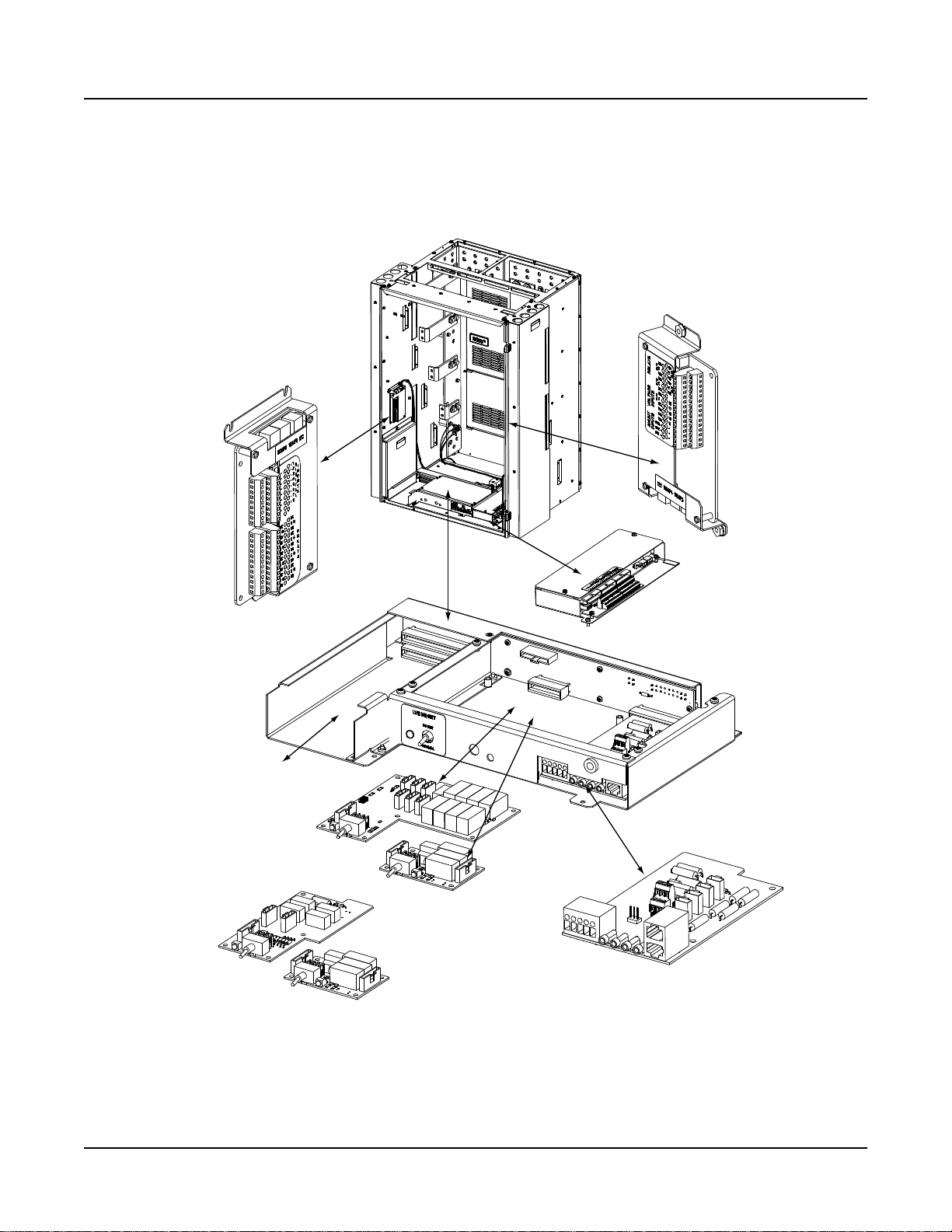
Installation Instructions IM581127000
IB2
(ACU+ Interface Board)
(located on inside sidepanel)
Optional EIB
(ACU+ Extended Interface Board)
(located on inside sidepanel)
Optional SM-DU+ and
Shunt Interface Board
4-Row Cabinet Shown,
Others Similar
(Front Door Removed in
Illustration for Clarity)
ACU+ Controller
Mounting Position
System Interface
Circuit Card
OR
Optional Manual Battery
Disconnect Circuit Card
Optional LVD
Driver Circuit Card
Optional LVD Driver
Lite Circuit Card
Optional Manual Battery
Disconnect Circuit Card
Spec. No. 581127000 (Model 710NPBA) Issue AB, March 22, 2012
EXTERNAL ALARM, REFERENCE, MONITORING, AND CONTROL CONNECTIONS
Circuit Card Locations
Refer to Figure 4-4.
Chapter 4. Making Electrical Connections Page 49
This document is property of Emerson Network Power, Energy Systems, North America, Inc. and contains confidential and proprietary information owned by Emerson Network Power, Energy
Systems, North America, Inc. Any copying, use, or disclosure of it without the written permission of Emerson Network Power, Energy Systems, North America, Inc. is strictly prohibited.
Figure 4-4
Circuit Card Locations
Page 58

IM581127000 Installation Instructions
Issue AB, March 22, 2012 Spec. No. 581127000 (Model 710NPBA)
System Interface Circuit Card
The System Interface Circuit Card provides connections for the following.
Refer to Figure 4-5.
RS-485 (used for communication with SM modules)
RS-232 (used for communication with a DPU)
External Battery Monitoring
External System FA Signal
External Battery FA Signal
Battery Tray FA Signal
System Voltage Monitoring Test Points
System Load Shunt Monitoring Test Points
Page 50 Chapter 4. Making Electrical Connections
This document is property of Emerson Network Power, Energy Systems, North America, Inc. and contains confidential and proprietary information owned by Emerson Network Power, Energy
Systems, North America, Inc. Any copying, use, or disclosure of it without the written permission of Emerson Network Power, Energy Systems, North America, Inc. is strictly prohibited.
Page 59

Installation Instructions IM581127000
J5
CAN
TB2
TP3 (+) and TP4 (-)
System Load
Shunt Monitoring
TP1 (+) and TP2 (-)
System Voltage
Monitoring
TB1-1: Battery Tray FA
TB1-2: External Battery FA
TB1-3: External System FA
TB1-4: External Battery Monitoring (-)
TB1-5: External Battery Monitoring (+)
1
1A 2A 3A
1B 2B 3B
5
RS485 Connection
TB2 1A: RS485+
TB2 2A: RS485-
RS232 Connection
TB2 1B: CGND
TB2 2B: TXD232
TB2 3B:RXD232
J1
J2
J3
J4
J8
TB2
TB1
TP1 TP2 TP3 TP4
J10
J5
TB1
Wire Size Capacity: 22-12 AWG.
Recommended Torque: 3.0 in-lbs.
FASignals: Battery applied to the terminal
turns in an alarm.
J1, J2, J3, J4
Distribution Panels FA Inputs
J8
Selects to power Controller
from “Battery Power” or not.
Shorting Jumper
No
Battery
Pwr
Battery
Pwr
External Internal
J8
J10
1
2
3
7
8
9
3 2 1
J10
Battery Monitoring External / Internal
(see TB1-4 and TB1-5 for
external monitoring points)
Shorting Jumper
CAN termination plug
must be installed.
System
Interface
Card
Spec. No. 581127000 (Model 710NPBA) Issue AB, March 22, 2012
Chapter 4. Making Electrical Connections Page 51
This document is property of Emerson Network Power, Energy Systems, North America, Inc. and contains confidential and proprietary information owned by Emerson Network Power, Energy
Systems, North America, Inc. Any copying, use, or disclosure of it without the written permission of Emerson Network Power, Energy Systems, North America, Inc. is strictly prohibited.
Figure 4-5
System Interface Circuit Card Connections
Page 60

IM581127000 Installation Instructions
Issue AB, March 22, 2012 Spec. No. 581127000 (Model 710NPBA)
IB2 (ACU+ Controller Interface Board)
The IB2 (ACU+ Controller Interface Board) provides connection points for digital inputs,
programmable relay outputs, and temperature probes. Refer to Figure 4-6.
Procedure
Digital Inputs and Relay Outputs: Digital input and relay output leads are connected to
screw-type terminal blocks located on the IB2 (ACU+ Controller Interface Board)
mounted inside the distribution cabinet. Recommended torque for these connections is 5
in-lbs.
a) Digital Inputs: Connect up to eight (8) digital inputs to the IB2 (ACU+ Controller
Interface Board). Note that you must supply both paths for the digital input
(either a positive or negative signal and the opposite polarity return path).
Observe proper polarity.
Note: +24V is factory wired to the DI8+ terminal for your convenience and
function predefined for ESTOP. Customer-furnished system ground
applied to terminal DI8- activates the ESTOP function. The ESTOP
function shuts down and locks out the rectifiers, opens the LVD’s, and
shuts down the converters. When the ESTOP signal is removed, LVD’s
close (if battery present) and converters restart. To restart the rectifiers;
turn AC power to the rectifiers OFF, wait 30 seconds or more, then turn
AC power to the rectifiers ON. Rectifiers can also be restarted via the
Local and Web-interface ACU+ menus using the “rectifier reset”
command.
The digital inputs can be programmed to provide an alarm when the signal is
applied (HIGH) or removed (LOW). Refer to the ACU+ User Instructions
(UM1M820BNA) for programming information.
b) Programmable Relay Outputs: The IB2 (ACU+ Controller Interface Board)
provides eight programmable alarm relays with Form-C contacts.
Note: The ACU+ relay assigned to “Critical Summary” alarm (relay 1 by default)
will operate in the “Fail Safe Mode”. “Fail Safe Mode” means Relay 1 is
de-energized during an alarm condition, opening the contacts between
the C and NO terminals, and closing the contacts between the C and NC
terminals.
The ACU+ remaining 7 relays energize during an alarm condition, closing
the contacts between the C and NO terminals, and opening the contacts
between the C and NC terminals.
The default ACU+ configuration programs these relays as follows. Refer to the
ACU+ User Instructions (UM1M820BNA) for programming information. Refer to
Optional EIB (ACU+ Controller Extended Interface Board) for relays 9-13, if
applicable. Refer to the configuration drawing (C-drawing) supplied with your
system for your system’s specific configuration.
Relay 1: Critical Summary Alarm
Relay 2: Major Summary Alarm
Relay 3: Over Voltage 1 Alarm
Relay 4: Under Voltage 1 Alarm
Relay 5: Under Voltage 2 Alarm
Relay 6: Mains Failure Alarm
Relay 7: Fuse Alarm
Relay 8: Rectifier Major Alarm (single rectifier fail alarm)
Page 52 Chapter 4. Making Electrical Connections
This document is property of Emerson Network Power, Energy Systems, North America, Inc. and contains confidential and proprietary information owned by Emerson Network Power, Energy
Systems, North America, Inc. Any copying, use, or disclosure of it without the written permission of Emerson Network Power, Energy Systems, North America, Inc. is strictly prohibited.
Page 61

Installation Instructions IM581127000
Spec. No. 581127000 (Model 710NPBA) Issue AB, March 22, 2012
Temperature Probes: Temperature probes are connected to the IB2 (ACU+ Controller
Interface Board) and/or optional EIB (ACU+ Controller Extended Interface Board)
mounted inside the distribution cabinet.
Note: Each temperature probe consists of two pieces that plug together to make a
complete probe. See SAG581127000 for part numbers and descriptions.
Up to two (2) temperature probes can be connected to the IB2 (ACU+ Interface
Board). Up to two (2) additional temperature probes can be connected to the
optional EIB (ACU+ Extended Interface Board). Any combination of the four (4)
temperature probes can be programmed to monitor ambient temperature and/or
battery temperature. A temperature probe set as a battery probe can also be
designated to be used for the battery charge temperature compensation feature, or
the battery charge temperature compensation feature can be programmed to use the
average or highest value of all battery temperature probes. The battery charge
temperature compensation feature allows the controller to automatically increase or
decrease the output voltage of the system to maintain battery float current as battery
temperature decreases or increases, respectively. Battery life can be extended when
an optimum charge voltage to the battery with respect to temperature is maintained.
A temperature probe set as a battery probe can also be used for controlling against
battery thermal runaway (BTRM feature). Refer to the ACU+ User Instructions
(UM1M820BNA) for programming information.
The temperature sensor end of the probe contains a tab with a 5/16” clearance hole
for mounting.
A temperature probe programmed to monitor battery temperature should be mounted
on the negative post of a battery cell to sense battery temperature. A temperature
probe used for battery charge temperature compensation or BTRM (Battery Thermal
Runaway Management) should also be mounted on the negative post of a battery
cell. A temperature probe programmed to monitor ambient temperature should be
mounted in a convenient location, away from direct sources of heat or cold.
Chapter 4. Making Electrical Connections Page 53
This document is property of Emerson Network Power, Energy Systems, North America, Inc. and contains confidential and proprietary information owned by Emerson Network Power, Energy
Systems, North America, Inc. Any copying, use, or disclosure of it without the written permission of Emerson Network Power, Energy Systems, North America, Inc. is strictly prohibited.
Page 62

IM581127000 Installation Instructions
* The ACU+ relay assigned to “Critical Summary” alarm (relay 1 by default)
will operate in the “FailSafe Mode”. “Fail Safe Mode” means Relay 1is
de-energized during an alarm condition, openingthe contacts between the
C and NO terminals, andclosing the contacts between the C and NCterminals.
The ACU+’s remaining seven (7) relays energize during an alarm condition, closing
the contacts between the C andNO terminals, and opening the contacts between
the C and NC terminals.
Not all I/Opoints are available for customerconnection (some are used forfactory
system connections).
J3-J9:
Wire Size Capacity: 16-26AWG.
Recommended Torque: 2.2 in-lbs.
MA4C5U31
IB2
DI1-
DI1+
DI2-
DI2+
DI3-
DI3+
J3
J4
J5
J6
J7
J8
J9
DI4-
DI4+
DI5-
DI5+
DI6-
DI6+
DI7-
DI7+
DI8-
DI8+
DO1_NC
DO2_NC
DO1_COM
DO2_COM
DO1_NO
DO2_NO
DO3_NC
DO4_NC
DO3_COM
DO4_COM
DO3_NO
DO4_NO
DO5_NC
DO6_NC
DO5_COM
DO6_COM
DO5_NO
DO6_NO
DO7_NC
DO8_NC
DO7_COM
DO8_COM
DO7_NO
DO8_NO
J11 1
J11 2
J11 3
J12 1
J12 2
J12 3
2
4
3
1
J2
6 5 4 3 2 1 6 5 4 3 2 1 6 5 4 3 2 1 6 5 4 3 2 1 6 5 4 3 2 1 6 5 4 3 2 1 6 5 4 3 2 1
STUPTUOYALER
STUPNILATIGID
Schematic Diagram of IB2 Board
IB2 TEMP
PROBE 1
IB2 TEMP
PROBE 2
-
J12
*
RELAY
SW1
7
J2
J11
5 3 1
Relay Output TerminalBlocks
Digital Input TerminalBlocksJ9 J8 J7
J6
J5 J4
J3
8 6 4
2
8 7 6 5 4 3
2 1
+
IB2 Board (Top View)
NO C NC
NO C NC
NO C NC
NO C NC
NO C NC
NO C NC
NO C NC
NO C NC
5 3 1
46 2
5
3
1
46 2
5 3 1
46 2
5 3 1
46 2
5 3 1
46 2
5 3 1
46 2
5 3 1
46 2
Connector
to ACU+
IB2 TEMP
PROBRE 1
IB2 TEMP
PROBE 2
IB2 Board Assembly
Issue AB, March 22, 2012 Spec. No. 581127000 (Model 710NPBA)
IB2 (Interface Board) Connections
Page 54 Chapter 4. Making Electrical Connections
This document is property of Emerson Network Power, Energy Systems, North America, Inc. and contains confidential and proprietary information owned by Emerson Network Power, Energy
Systems, North America, Inc. Any copying, use, or disclosure of it without the written permission of Emerson Network Power, Energy Systems, North America, Inc. is strictly prohibited.
Figure 4-6
Page 63

Installation Instructions IM581127000
Number of
Battery Shunts
Number of
Load Shunts
Connect to EIB Shunt
Inputs as Follows
1
0
Shunt 1 – Battery 1
Shunt 2 – none
Shunt 3 – none
2
0
Shunt 1 – Battery 1
Shunt 2 – Battery 2
Shunt 3 – none
3
0
Shunt 1 – Battery 1
Shunt 2 – Battery 2
Shunt 3 – Battery 3
0
1
Shunt 1 – none
Shunt 2 – none
Shunt 3 – Load 1
0
2
Shunt 1 – none
Shunt 2 – Load 2
Shunt 3 – Load 1
0
3
Shunt 1 – Load 3
Shunt 2 – Load 2
Shunt 3 – Load 1
1
1
Shunt 1 – Battery 1
Shunt 2 – none
Shunt 3 – Load 1
2
1
Shunt 1 – Battery 1
Shunt 2 – Battery 2
Shunt 3 – Load 1
1
2
Shunt 1 – Battery 1
Shunt 2 – Load 2
Shunt 3 – Load 1
Spec. No. 581127000 (Model 710NPBA) Issue AB, March 22, 2012
Optional EIB (ACU+ Controller Extended Interface Board)
The optional EIB (ACU+ Controller Extended Interface Board) provides additional
connection points for voltage and current inputs, programmable relay outputs, and
temperature probes. Refer to Figure 4-7.
Procedure
Voltage Inputs, Current Inputs, and Programmable Relay Outputs: Voltage input,
current input, and relay output leads are connected to screw-type terminal blocks located
on the optional EIB (ACU+ Controller Extended Interface Board) mounted inside the
distribution cabinet. Recommended torque for these connections is 5 in-lbs.
a) Current Inputs: Connect up to three (3) shunt inputs to the EIB (Extended
Interface Board). Observe proper polarity. Refer to Table 4-2 to determine what
shunt input to connect to on the EIB board. Refer to the ACU+ User Instructions
(UM1M820BNA) and program the shunt input parameters found in the EIB menu.
Chapter 4. Making Electrical Connections Page 55
This document is property of Emerson Network Power, Energy Systems, North America, Inc. and contains confidential and proprietary information owned by Emerson Network Power, Energy
Systems, North America, Inc. Any copying, use, or disclosure of it without the written permission of Emerson Network Power, Energy Systems, North America, Inc. is strictly prohibited.
Table 4-2
Shunt Inputs to EIB Interface Board
b) Voltage Inputs for Battery Block and Battery Midpoint Monitoring: The
ACU+ can monitor battery blocks (12V blocks) or midpoint battery voltage of
battery strings connected to the EIB assembly. The EIB assembly provides a
Page 64

IM581127000 Installation Instructions
Issue AB, March 22, 2012 Spec. No. 581127000 (Model 710NPBA)
total of eight (8) DC voltage inputs for these connections. An alarm is issued
when either battery block voltage or battery midpoint voltage is abnormal.
Refer to Figure 4-8 for connection details. Refer to the ACU+ User Instructions
(UM1M820BNA) and program the following parameters found in the EIB menu.
Battery Block Monitoring
Voltage Type: Set to “24 (Block 2)”. This selects the EIB to monitor up to
four (4) 24V battery strings with two (2) 12V blocks per string
BlockVDiff(12V): This menu item appears if “24 (Block 2)” is selected above.
Set to the alarm threshold for battery block monitoring per site requirements.
The ACU+ issues an alarm when any block voltage of any battery string has
an abnormal value. The alarm is issued when the difference between any
block voltage and a reference voltage is greater than the value of the block
voltage difference setting.
Block In-Use: Set to the number of 12V battery blocks being used.
Midpoint Monitoring
Voltage Type: Set to “Midpoint”. This selects the EIB to monitor the midpoint
voltage of up to eight (8) battery strings.
BlockVDiff(Mid): This menu item appears if “Midpoint” is selected above.
Set to the alarm threshold for battery midpoint monitoring per site
requirements. The ACU+ issues an alarm when any battery midpoint voltage
of any battery string has an abnormal value. The alarm is issued when the
difference between any battery midpoint voltage and a reference voltage is
greater than the value of the block voltage difference setting.
Block In-Use: Set to number of 12V battery blocks being used.
c) Programmable Relay Outputs: The EIB (ACU+ Controller Extended Interface
Board) provides five programmable alarm relays with Form-C contacts.
Note: The relays energize during an alarm condition, closing the contacts
between the C and NO terminals, and opening the contacts between the
C and NC terminals.
The default ACU+ configuration programs these relays as follows. Refer to the
ACU+ User Instructions (UM1M820BNA) for programming information.
Relay 9: Converter Critical Alarm (multiple converter fail alarms)
Relay 10: Converter Major Alarm (single converter fail alarm)
Relay 11: Rectifier Critical Alarm (multiple rectifier fail alarms)
Relay 12: High 2 Battery Temp Alarm
Relay 13: Battery Discharge Alarm
Temperature Probes: Temperature probes are connected to the optional EIB (ACU+
Controller Extended Interface Board) mounted inside the distribution cabinet. Refer to
“Temperature Probes” in the previous section.
Page 56 Chapter 4. Making Electrical Connections
This document is property of Emerson Network Power, Energy Systems, North America, Inc. and contains confidential and proprietary information owned by Emerson Network Power, Energy
Systems, North America, Inc. Any copying, use, or disclosure of it without the written permission of Emerson Network Power, Energy Systems, North America, Inc. is strictly prohibited.
Page 65

Installation Instructions IM581127000
MA455U41
EIB
SH1-
SH1+
SH2-
SH2+
SH3-
SH3+
J5
J6 J7
J8 J9
DCV1
DCV2
DCV3
DCV4
DCV5
DCV6
DCV7
DO5_NC
DCV8
DO5_COM
DO1_NC
DO2_NC
DO1_COM
DO2_COM
DO1_NO
DO2_NO
DO3_NC
DO4_NC
DO3_COM
DO4_COM
DO3_NO
DO4_NO
J3 1
J3 2
J3 3
J4 1
J4 2
J4 3
2 4 3 1
J2
DO5_NO
1 2 3 4 5 6 1 2 3 4 5 6 1 2 3 4 5 6 1 2 3 4 5 6 1 2 3 4 5 6
SHUNT
INPUTS
VOLTAGE
INPUTS
RELAY OUTPUTS
EIB TEMP
PROBE 2
or SM-TEMP
EIB TEMP
PROBE 1
or SM-TEMP
Schematic Diagram of EIB Board
J5-J9
Wire Size Capacity: 16-26 AWG.
Recommended Torque: 2.2 in-lbs.
EIB Board
J5 J6 J7 J8 J9
2
4
6
31 5
2
4
6
31 5
2
4
6
31 5
2
4
6
31 5
2
4
6
31 5
Spec. No. 581127000 (Model 710NPBA) Issue AB, March 22, 2012
Chapter 4. Making Electrical Connections Page 57
This document is property of Emerson Network Power, Energy Systems, North America, Inc. and contains confidential and proprietary information owned by Emerson Network Power, Energy
Systems, North America, Inc. Any copying, use, or disclosure of it without the written permission of Emerson Network Power, Energy Systems, North America, Inc. is strictly prohibited.
Figure 4-7
EIB (Extended Interface Board) Connections
Page 66

IM581127000 Installation Instructions
Battery Midpoint Monitoring
Battery Block Monitoring
Battery
String 1
to
DCV1
(J6-1)
to
DCV2
(J6-2)
to
DCV3
(J6-3)
to
DCV4
(J6-4)
to
DCV5
(J6-5)
to
DCV6
(J6-6)
to
DCV7
(J7-1)
to
DCV8
(J7-3)
Battery
String 2
Battery
String 3
EIB BoardVoltage Inputs
Battery
String 4
Battery
String 5
Battery
String 6
Battery
String 7
Battery
String 8
Rectifiers
+24V
Return
Load Shunt
Load
Battery
String 1
to
DCV1
(J6-1)
to
DCV2
(J6-2)
to
DCV3
(J6-3)
to
DCV4
(J6-4)
to
DCV5
(J6-5)
to
DCV6
(J6-6)
to
DCV7
(J7-1)
to
DCV8
(J7-3)
Battery
String 2
EIB BoardVoltage Inputs
Battery
String 3
Battery
String 4
Rectifiers
+
12V
-
+
12V
-
+
12V
-
+
12V
-
+
12V
-
+
12V
-
+
12V
-
+
12V
-
+
12V
-
+
12V
-
+
12V
-
+
12V
-
+
12V
-
+
12V
-
+
12V
-
+
12V
-
+
12V
-
+
12V
-
+
12V
-
+
12V
-
+
12V
-
+
12V
-
+
12V
-
+
12V
-
+24V
Return
Load Shunt
Load
Issue AB, March 22, 2012 Spec. No. 581127000 (Model 710NPBA)
Page 58 Chapter 4. Making Electrical Connections
This document is property of Emerson Network Power, Energy Systems, North America, Inc. and contains confidential and proprietary information owned by Emerson Network Power, Energy
Systems, North America, Inc. Any copying, use, or disclosure of it without the written permission of Emerson Network Power, Energy Systems, North America, Inc. is strictly prohibited.
Figure 4-8
Sample Battery Block or Battery Midpoint Monitoring Connections
Page 67

Installation Instructions IM581127000
System Interface
Circuit Card CAN
Port Pin Number
SM-Temp Module
CAN Port
Pin Number
1 (CAN L)
TB1-3 (CAN L)
2 (CAN H)
TB1-3 (CAN H)
3
-- 4 -- 5 --
6
--
7
-- 8 --
Spec. No. 581127000 (Model 710NPBA) Issue AB, March 22, 2012
Optional SM-DU+ and Shunt Interface Board
The optional SM-DU+ and Shunt Interface Board provides connections for up to twentyfive (25) shunt inputs. Inputs are factory connected to any distribution positions/devices
containing shunts. Refer to Figure 4-9.
Procedure
Current Inputs: Connect up to twenty-five (25) shunt inputs to the Shunt Interface
Board. Observe proper polarity. Note that some inputs may be factory connected,
depending on distribution devices installed. Refer to the ACU+ User Instructions
(UM1M820BNA) for programming information for the unused inputs.
Note: The shunt needs to be installed in the hot (+24V) bus. Connect the plus side of
the shunt to the positive shunt input on the SM-DU+. Connect the negative side
of the shunt to the negative shunt input on the SM-DU+.
Optional SM-Temp Module
The analog output of the SM-Temp Module may be connected to an ACU+ temperature
port input. In lieu of connecting the analog output of the SM-TEMP module to an ACU+
temperature port input, the SM-TEMP module can simply be connected at the end of the
ACU+ CAN bus (requires ACU+ version 3.02 or later). Refer to the SM-Temp Module
Installation and User instructions (UM547490) for details.
CAN Bus Procedure
Remove the CAN termination plug from the bottom CAN connector on the System
Interface circuit card. Connect the SM-Temp Module CAN bus to the bottom CAN
connector on the System Interface circuit card. Refer to Table 4-3 for pin-outs. Ensure
the last SM-Temp Module (or if only one) has a CAN termination strap as shown in the
SM-Temp Module Installation and User instructions (UM547490).
Chapter 4. Making Electrical Connections Page 59
This document is property of Emerson Network Power, Energy Systems, North America, Inc. and contains confidential and proprietary information owned by Emerson Network Power, Energy
Systems, North America, Inc. Any copying, use, or disclosure of it without the written permission of Emerson Network Power, Energy Systems, North America, Inc. is strictly prohibited.
Table 4-3
CAN Connections
Page 68

IM581127000 Installation Instructions
TB1 - TB2
Wire Size Capacity: 16-26 AWG.
Recommended Torque: 2.2 in-lbs.
Shunt Interface Board
SMDU+
2
1
J3
1
2
J1
SHUNT
INPUTS
541127
SHUNT
1
2
3
4
5
6
7
8
9
10
11
12
13
14
15
16
17
18
19
20
21
22
23
24
25
26
J1
1
2
3
4
5
6
7
8
9
10
11
12
13
14
15
16
17
18
19
20
21
22
23
24
25
26
J2
SHUNT25+
SHUNT25SHUNT24+
SHUNT24SHUNT23+
SHUNT23SHUNT22+
SHUNT22SHUNT21+
SHUNT21SHUNT20+
SHUNT20SHUNT19+
SHUNT19SHUNT18+
SHUNT18SHUNT17+
SHUNT17SHUNT16+
SHUNT16SHUNT15+
SHUNT15SHUNT14+
SHUNT14-
TB2
25A
25B
24A
24B
23A
23B
22A
22B
21A
21B
20A
20B
19A
19B
18A
18B
17A
17B
16A
16B
15A
15B
14A
14B
SHUNT12+
SHUNT12-
SHUNT13+
SHUNT13-
SHUNT11+
SHUNT11SHUNT10+
SHUNT10SHUNT9+
SHUNT9SHUNT8+
SHUNT8SHUNT7+
SHUNT7SHUNT6+
SHUNT6SHUNT5+
SHUNT5SHUNT4+
SHUNT4SHUNT3+
SHUNT3SHUNT2+
SHUNT2SHUNT1+
SHUNT1-
TB1
12A
12B
13A
13B
11A
11B
10A
10B
9A
9B
8A
8B
7A
7B
6A
6B
5A
5B
4A
4B
3A
3B
2A
2B
1A
1B
3
INTERFACE
1A
1B
TB1 TB2
J2J1
Schematic Diagram ofSM-DU+ and Shunt Interface Board
SM-DU+ and Shunt
Interface Board
-
+
Issue AB, March 22, 2012 Spec. No. 581127000 (Model 710NPBA)
SM-DU+ and Shunt Interface Board Connections
Page 60 Chapter 4. Making Electrical Connections
This document is property of Emerson Network Power, Energy Systems, North America, Inc. and contains confidential and proprietary information owned by Emerson Network Power, Energy
Systems, North America, Inc. Any copying, use, or disclosure of it without the written permission of Emerson Network Power, Energy Systems, North America, Inc. is strictly prohibited.
Figure 4-9
Page 69

Installation Instructions IM581127000
Port Pin Number
Name
Definition
1
Tx+
Write Signal +
2
Tx-
Write Signal -
3
Rx+
Read Signal +
4
--
no connection
5
--
no connection
6
Rx-
Read Signal -
7
--
no connection
8
--
no connection
ESC ENT
Ethernet Port (RJ-45)
Spec. No. 581127000 (Model 710NPBA) Issue AB, March 22, 2012
ETHERNET CONNECTION
Note: If the Web Interface is not being used with this system, skip this procedure.
The ACU+ provides a Web Interface via an Ethernet connection to a TCP/IP network. An
RJ-45 10BaseT jack is provided on the front of the ACU+ for connection into a customer's
network running TCP/IP. This jack has a standard Ethernet pin configuration scheme,
twisted pair. Refer to Figure 4-10 for location and Table 4-4 for pin outs. Use shielded
Ethernet cable (grounded at both ends). Note that the ACU+ RJ-45 jack is connected to
chassis ground. Refer to the ACU+ User Instructions (UM1M820BNA) for operational
details.
Note: You can access the Web pages of the power system locally by using a
"crossover" or “straight” cable connected directly between your PC and the ACU+.
Warning: The intra-building port(s) of the equipment or subassembly is suitable for
connection to intra-building or unexposed wiring or cabling only. The intrabuilding port(s) of the equipment or subassembly MUST NOT be metallically
connected to the interfaces that connect to the OSP or its wiring. These
interfaces are designed for use as intra-building interfaces only (Type 2 or
Type 4 ports as described in GR-1089-CORE, Issue 4) and require isolation
from the exposed OSP cabling. The addition of Primary Protectors is not
sufficient protection in order to connect these interfaces metallically to OSP
wiring.
The intra-building port (RJ-45) of the equipment or subassembly must use
shielded intra-building cabling/wiring that is grounded at both ends.
Table 4-4
ACU+ RJ-45 Ethernet Port Pin Configuration
Figure 4-10
ACU+ Ethernet Port
This document is property of Emerson Network Power, Energy Systems, North America, Inc. and contains confidential and proprietary information owned by Emerson Network Power, Energy
Systems, North America, Inc. Any copying, use, or disclosure of it without the written permission of Emerson Network Power, Energy Systems, North America, Inc. is strictly prohibited.
Chapter 4. Making Electrical Connections Page 61
Page 70

IM581127000 Installation Instructions
Issue AB, March 22, 2012 Spec. No. 581127000 (Model 710NPBA)
CONTROL BUS CONNECTIONS BETWEEN CONTROLLER AND MODULE MOUNTING SHELVES
Each module mounting shelf in the system is daisy-chained to the controller. A connector
is located at the top of each shelf and another at the bottom of each shelf. These
connectors are used to interconnect the shelves to the controller. Refer to Figure 4-11
for connector locations. These connections are factory made for shelves factory
installed. The connection must be made if a field expansion shelf is installed as shown in
Figure 4-11.
The top connector of the top most module mounting assembly connects to the
controller.
The bottom connector of a shelf plugs into the top connector on the shelf below it.
The bottom connector on the bottom most shelf must have the termination connector.
Page 62 Chapter 4. Making Electrical Connections
This document is property of Emerson Network Power, Energy Systems, North America, Inc. and contains confidential and proprietary information owned by Emerson Network Power, Energy
Systems, North America, Inc. Any copying, use, or disclosure of it without the written permission of Emerson Network Power, Energy Systems, North America, Inc. is strictly prohibited.
Page 71

Installation Instructions IM581127000
Connector Location
(to Controller)
Connector Location
(to shelf mountedbelow orif bottom
shelf to termination connector)
Rear
Connector Location
(to shelf mounted above)
Front
588705200
Expansion Shelf
588705201 Shelf or Top Shelf in 588705202,
588705203, or 588705204 Shelf Assembly
Communications Cable Connections
Brown and
Brown/White
Wires
Slate and
Slate/White
Wires
Distribution
Cabinet
Module
Mounting
Shelf
Expansion
Module
Mounting
Shelf
Communications Cable Connections
Distribution
Cabinet
Module
Mounting
Shelf
Brown and
Brown/White
Wires
Slate and
Slate/White
Wires
Spec. No. 581127000 (Model 710NPBA) Issue AB, March 22, 2012
Chapter 4. Making Electrical Connections Page 63
This document is property of Emerson Network Power, Energy Systems, North America, Inc. and contains confidential and proprietary information owned by Emerson Network Power, Energy
Systems, North America, Inc. Any copying, use, or disclosure of it without the written permission of Emerson Network Power, Energy Systems, North America, Inc. is strictly prohibited.
Control Bus Connections between Controller and Module Mounting Shelves
Figure 4-11
Page 72

IM581127000 Installation Instructions
Issue AB, March 22, 2012 Spec. No. 581127000 (Model 710NPBA)
CONNECTING LIST 60 CONVERTER OUTPUT JUMPERS
Note: If List 60 is not provided, skip this procedure.
Note: If the power system was ordered in a relay rack, this procedure has been
performed at the factory.
Procedure
1) Locate the output jumpers (labeled -48V) supplied with List 60 (P/O kit P/N
540860). There are two (2) cables per List 60.
2) Open the distribution cabinet’s front door by turning the latch in the
counterclockwise position.
3) Loosen the (2) screws holding the plastic shield over the circuit breakers or
fuseholders on the dual voltage distribution panel. Slide the shield upwards and
remove.
4) Connect the output jumpers to the distribution bus panel subsystem (-48V) input
terminals as shown in Figure 4-12. Apply electrical anti-oxidizing compound to
lug mating surfaces before connecting. Mount two lugs back-to-back per
mounting position if required. Torque as shown in the figure.
5) Route the output jumpers installed in the previous step over the top of the
distribution bus panel ground bar, toward the back of the cabinet, and down
through the opening in the bottom of the distribution cabinet (between the cabinet
main busbars).
6) Route the output jumpers to the converter output terminals as shown in Figure
4-12.
7) Connect the output jumpers to the converter output terminals as shown in Figure
4-12. Apply electrical anti-oxidizing compound to lug mating surfaces before
connecting. Torque as shown in the figure.
8) Install the plastic shield that was removed in a previous step, over the circuit
breakers or fuseholders. To do so, position the shield and slide downwards on
screws. Tighten screws.
Page 64 Chapter 4. Making Electrical Connections
This document is property of Emerson Network Power, Energy Systems, North America, Inc. and contains confidential and proprietary information owned by Emerson Network Power, Energy
Systems, North America, Inc. Any copying, use, or disclosure of it without the written permission of Emerson Network Power, Energy Systems, North America, Inc. is strictly prohibited.
Page 73

Installation Instructions IM581127000
List DA (ListsDB, DC,and DD similar.)
Rear
588705201 Module Mounting Shelf
or Top Shelf in 588705202, 588705203,
or 588705204 ShelfAssembly
Rear
588705200 Expansion
Module Mounting Shelf
Shorting Block if 4th shelf
has Converter Option.
Dual Voltage Distribution Panel
If more than three shelves with the Converter Option
installed, connect /–48/ jumpers for the4th shelf here.
Assembly order is: lug, 1/4" flat washer, 1/4" lockwasher,
1/4-20 nut. Torque to 84 in-lbs. Note that a shorting block
will be factory installed in this distribution device position.
Connect /–48/ jumpers to an available landinghere.
Assembly order is: lug, 1/4" flat washer,
1/4" lock washer, 1/4-20bolt.
Torque to 84 in-lbs.
Connect /–48/ jumpershere.
Assembly order is: lug, 1/4" flat washer,
1/4" lock washer, 1/4-20 nut.
Torque to 84in-lbs.
Connect /–48/ jumpers here.
Assembly order is: lug, 1/4" flat washer,
1/4" lock washer,1/4-20 nut.
Torque to 84in-lbs.
Spec. No. 581127000 (Model 710NPBA) Issue AB, March 22, 2012
Figure 4-12
Chapter 4. Making Electrical Connections Page 65
This document is property of Emerson Network Power, Energy Systems, North America, Inc. and contains confidential and proprietary information owned by Emerson Network Power, Energy
Systems, North America, Inc. Any copying, use, or disclosure of it without the written permission of Emerson Network Power, Energy Systems, North America, Inc. is strictly prohibited.
Installing Converter Output Cables
Page 74

IM581127000 Installation Instructions
Issue AB, March 22, 2012 Spec. No. 581127000 (Model 710NPBA)
LOAD CONNECTIONS
Loads are connected to the various distribution panels located inside the distribution
cabinet, as detailed in this section.
Recommended Torques
72 in-lbs for 1/4-inch hardware (when using standard flat and lock washer).
300 in-lbs for 3/8-inch hardware (when using standard flat and lock washer).
Page 66 Chapter 4. Making Electrical Connections
This document is property of Emerson Network Power, Energy Systems, North America, Inc. and contains confidential and proprietary information owned by Emerson Network Power, Energy
Systems, North America, Inc. Any copying, use, or disclosure of it without the written permission of Emerson Network Power, Energy Systems, North America, Inc. is strictly prohibited.
Page 75

Installation Instructions IM581127000
+24VDC Load
Connections
Load Return
Connections
LOADAND LOAD RETURN CONNECTIONS
1/4-20 Studson 5/8” Centers
(Customer must supply or order additional hardware)
Maximum Lug Width: 0.625 inches.
Return Busbar
(not includedwith ListAB)
Observe proper
polarity when making
load connections.
WARNING!
Caution:A circuit breaker or fuse witha rating of100A orgreater
SHALLHAVE an empty mounting position between it and any
other overcurrent protectivedevice.
+24VDC Load
Connections
Load Return
Connections
LOADAND LOAD RETURN CONNECTIONS
3/8-16 Captive Nuts on 1” Centers
(Customer must supply or order additional hardware)
Maximum Lug Width:1.375 inches.
Return Busbar
(not includedwith ListAD)
Observe proper
polarity whenmaking
load connections.
WARNING!
For an800A circuit breaker,
load mustnot exceed 600A.
Spec. No. 581127000 (Model 710NPBA) Issue AB, March 22, 2012
Load Connections to Single Voltage Distribution Panels
List AA: +24V Distribution Panel (with Return Busbar) and List AB: +24V Distribution Panel (without Return Busbar), (24) Bullet/TPS/TLS Circuit Breaker/Fuse Positions
List AC: +24V Distribution Panel (with Return Busbar) and List AD: +24V Distribution Panel (without Return Busbar), (4) GJ/218 Circuit Breaker Positions
Chapter 4. Making Electrical Connections Page 67
This document is property of Emerson Network Power, Energy Systems, North America, Inc. and contains confidential and proprietary information owned by Emerson Network Power, Energy
Systems, North America, Inc. Any copying, use, or disclosure of it without the written permission of Emerson Network Power, Energy Systems, North America, Inc. is strictly prohibited.
Page 76

IM581127000 Installation Instructions
+24VDC Load
Connections
LOAD CONNECTIONS
3/8-16 Captive Nuts on 1” Centers
(Customer mustsupply or orderadditional hardware)
Maximum Lug Width: 1.88 inches.
Observe proper
polarity when making
load connections.
WARNING!
For an 800Acircuit breaker,
load must not exceed 600A.
+24VDC Load
Connections
LOAD CONNECTIONS
3/8-16 Captive Nuts on 1” Centers
(Customer must supply or order additional hardware)
Maximum Lug Width: 1.88 inches.
Observe proper
polarity when making
load connections.
WARNING!
For an 800A circuit breaker,
load must not exceed 600A.
Issue AB, March 22, 2012 Spec. No. 581127000 (Model 710NPBA)
List AE: +24V Distribution Panel, (2) TPH Fuse Positions (without Shunts) (without Return Busbar)
List AF: +24V Distribution Panel, (2) TPH Fuse Positions (with Shunts) (without Return Busbar)
Page 68 Chapter 4. Making Electrical Connections
This document is property of Emerson Network Power, Energy Systems, North America, Inc. and contains confidential and proprietary information owned by Emerson Network Power, Energy
Systems, North America, Inc. Any copying, use, or disclosure of it without the written permission of Emerson Network Power, Energy Systems, North America, Inc. is strictly prohibited.
Page 77

Installation Instructions IM581127000
+24VDC Load
Connections
LOAD CONNECTIONS
3/8-16 Captive Nuts on 1” Centers
(Customer must supply or order additional hardware)
Maximum Lug Width: 1.75inches.
Maximum fuse size is 400A.
Observe proper
polarity when making
load connections.
WARNING!
+24VDC Load
Connections
Observe proper
polarity when making
load connections.
WARNING!
LOAD CONNECTIONS
3/8-16 Captive Nutson 1” Centers
(Customer must supply or order additional hardware)
Maximum Lug Width: 1.75 inches.
Maximum fuse size is 400A.
Spec. No. 581127000 (Model 710NPBA) Issue AB, March 22, 2012
List AG: +24V Distribution Panel, (4) TPH Fuse Positions (without Shunts) (without Return Busbar)
List AH: +24V Distribution Panel, (4) TPH Fuse Positions (with Shunts) (without Return Busbar)
Chapter 4. Making Electrical Connections Page 69
This document is property of Emerson Network Power, Energy Systems, North America, Inc. and contains confidential and proprietary information owned by Emerson Network Power, Energy
Systems, North America, Inc. Any copying, use, or disclosure of it without the written permission of Emerson Network Power, Energy Systems, North America, Inc. is strictly prohibited.
Page 78

IM581127000 Installation Instructions
+24VDC Load
Connections
LOAD CONNECTIONS
3/8-16 Studson 1” Centers
(Customer mustsupply or order additional hardware)
Maximum Lug Width: 1.5 inches.
Observe proper
polarity when making
load connections.
WARNING!
+24VDC Load
Connections
LOAD CONNECTIONS
3/8-16 Studs on 1” Centers
(Customer must supply or order additional hardware)
Maximum Lug Width: 1.5 inches.
Observe proper
polarity when making
load connections.
WARNING!
Issue AB, March 22, 2012 Spec. No. 581127000 (Model 710NPBA)
List AJ: +24V Distribution Panel, (4) TPL-B Fuse Positions (without Shunts) (without Return Busbar)
List AK: +24V Distribution Panel, (4) TPL-B Fuse Positions (with Shunts) (without Return Busbar)
Page 70 Chapter 4. Making Electrical Connections
This document is property of Emerson Network Power, Energy Systems, North America, Inc. and contains confidential and proprietary information owned by Emerson Network Power, Energy
Systems, North America, Inc. Any copying, use, or disclosure of it without the written permission of Emerson Network Power, Energy Systems, North America, Inc. is strictly prohibited.
Page 79

Installation Instructions IM581127000
Load
Connections
Load Return
Connections
LOAD AND LOAD RETURN CONNECTIONS
1/4-20 Studs on 5/8” Centers
(Customer must supply
or order additional
hardware)
Maximum Lug Width:
0.625 inches.
-
4
8
V
D
i
s
t
r
i
b
u
t
i
o
n
+
2
4
V
D
i
s
t
r
i
b
u
t
i
o
n
Observe proper
polarity when making
load connections.
WARNING!
Caution: A circuit breaker or fuse with a rating
of 100A or greater SHALL HAVE an empty
mounting position between it and any
other overcurrent protective device.
Load
Connections
Load Return
Connections
LOAD AND LOAD RETURNCONNECTIONS
1/4-20 Studs on 5/8” Centers
(Customer must supply
or order additional
hardware)
Maximum Lug Width:
0.625 inches.
-
4
8
V
D
i
s
t
r
i
b
u
t
i
o
n
+
2
4
V
D
i
s
t
r
i
b
u
t
i
o
n
Observe proper
polarity when making
load connections.
WARNING!
Caution:A circuit breakeror fuse witha rating
of 100A or greater SHALL HAVE an empty
mounting position between it and any
other overcurrent protective device.
Spec. No. 581127000 (Model 710NPBA) Issue AB, March 22, 2012
Load Connections to Dual Voltage Distribution Panels
List DA: +24V/-48V Distribution Panel, (17) +24V Bullet/TPS/TLS Circuit Breaker/Fuse Positions (with Return Busbar) and (4) –48V Bullet/TPS/TLS Circuit Breaker/Fuse Positions (with Return Busbar)
List DB: +24V/-48V Distribution Panel, (13) +24V Bullet/TPS/TLS Circuit Breaker/Fuse Positions (with Return Busbar) and (8) –48V Bullet/TPS/TLS Circuit Breaker/Fuse Positions (with Return Busbar)
Chapter 4. Making Electrical Connections Page 71
This document is property of Emerson Network Power, Energy Systems, North America, Inc. and contains confidential and proprietary information owned by Emerson Network Power, Energy
Systems, North America, Inc. Any copying, use, or disclosure of it without the written permission of Emerson Network Power, Energy Systems, North America, Inc. is strictly prohibited.
Page 80

IM581127000 Installation Instructions
Load
Connections
Load Return
Connections
LOADAND LOADRETURN CONNECTIONS
1/4-20 Studs on 5/8” Centers
(Customer must supply
or order additional
hardware)
Maximum Lug Width:
0.625 inches.
-
4
8
V
D
i
s
t
r
i
b
u
t
i
o
n
+
2
4
V
D
i
s
t
r
i
b
u
t
i
o
n
Observe proper
polarity when making
load connections.
WARNING!
Caution:A circuit breaker or fuse with a rating
of 100A or greater SHALL HAVE an empty
mounting position between it and any
other overcurrent protective device.
Load
Connections
-
4
8
V
D
i
s
t
r
i
b
u
t
i
o
n
+
2
4
V
D
i
s
t
r
i
b
u
t
i
o
n
Load Return
Connections
LOAD AND LOAD RETURN CONNECTIONS
1/4-20 Studs on 5/8” Centers
(Customer must supply
or orderadditional
hardware)
Maximum LugWidth:
0.625 inches.
Observe proper
polarity whenmaking
load connections.
WARNING!
Caution:A circuit breaker or fuse with a rating
of 100Aor greater SHALLHAVE an empty
mounting position between it and any
other overcurrent protective device.
Issue AB, March 22, 2012 Spec. No. 581127000 (Model 710NPBA)
List DC: +24V/-48V Distribution Panel, (9) +24V Bullet/TPS/TLS Circuit Breaker/Fuse Positions (with Return Busbar) and (12) –48V Bullet/TPS/TLS Circuit Breaker/Fuse Positions (with Return Busbar)
List DD: +24V/-48V Distribution Panel, (5) +24V Bullet/TPS/TLS Circuit Breaker/Fuse Positions (with Return Busbar) and (16) –48V Bullet/TPS/TLS Circuit Breaker/Fuse Positions (with Return Busbar)
Page 72 Chapter 4. Making Electrical Connections
This document is property of Emerson Network Power, Energy Systems, North America, Inc. and contains confidential and proprietary information owned by Emerson Network Power, Energy
Systems, North America, Inc. Any copying, use, or disclosure of it without the written permission of Emerson Network Power, Energy Systems, North America, Inc. is strictly prohibited.
Page 81

Installation Instructions IM581127000
Load and/or Battery
Return Connections
LOADAND/OR BATTERY RETURN CONNECTIONS
3/8-16 Captive Nuts on 1” Centers
(Customer must supply or order additional hardware)
Maximum Lug Width: 1.38 inches.
Load ReturnLeads
+24VDC Load Leads
Wire SizeCapacity: 26-14 AWG.
Recommended Torque: 4.5 in-lbs.
35A maximum capacity per block.
Maximum GMT fuse size is 15A.
Spec. No. 581127000 (Model 710NPBA) Issue AB, March 22, 2012
Load Connections to Return Bar
List GA: Return Bar Panel
Load Connections to GMT Distribution Fuse Block
Optional Bullet Nose 6-Position GMT Distribution Fuse Block
Chapter 4. Making Electrical Connections Page 73
This document is property of Emerson Network Power, Energy Systems, North America, Inc. and contains confidential and proprietary information owned by Emerson Network Power, Energy
Systems, North America, Inc. Any copying, use, or disclosure of it without the written permission of Emerson Network Power, Energy Systems, North America, Inc. is strictly prohibited.
Page 82

IM581127000 Installation Instructions
Issue AB, March 22, 2012 Spec. No. 581127000 (Model 710NPBA)
BATTERY CONNECTIONS
Important Safety Instructions
Danger: Adhere to the “Important Safety Instructions” presented at the front of
this document.
Warning: Observe proper polarity when making battery connections.
Recommended Torques
72 in-lbs for 1/4-inch hardware (when using standard flat and lock washer).
300 in-lbs for 3/8-inch hardware (when using standard flat and lock washer).
180 in-lbs for 3/8-inch hardware (when using a Belleville lock washer).
Battery Connections to Optional Battery Disconnect Distribution Panels
Danger: Adhere to the “Important Safety Instructions” presented at the front of
this document.
Battery strings are connected to the various battery disconnect distribution panels (if
furnished) located inside the distribution cabinet, as detailed in the illustrations in this
section.
Page 74 Chapter 4. Making Electrical Connections
This document is property of Emerson Network Power, Energy Systems, North America, Inc. and contains confidential and proprietary information owned by Emerson Network Power, Energy
Systems, North America, Inc. Any copying, use, or disclosure of it without the written permission of Emerson Network Power, Energy Systems, North America, Inc. is strictly prohibited.
Page 83

Installation Instructions IM581127000
+24VDC Battery
Connections
Battery Return
Connections
BATTERYAND BATTERY RETURN CONNECTIONS
1/4-20 Studs on 5/8” Centers Maximum Lug Width:0.625 inches.
(Customer must supply
or order additional
hardware)
Return Busbar
(not included with List BB)
Observe proper polarity
when making battery
connections.
WARNING!
Caution:A circuit breaker orfuse with a rating
of 100A orgreater SHALL HAVE an empty
mounting position between it and any
other overcurrent protectivedevice.
+24VDC Battery
Connections
Battery Return
Connections
BATTERY AND BATTERY RETURNCONNECTIONS
3/8-16 Captive Nuts on 1” Centers
(Customer must supply
or order additional
hardware)
Maximum Lug Width:
1.375 inches.
Return Busbar
(not included
with List BD)
Observe proper polarity
when making battery
connections.
WARNING!
For an800A circuit breaker,
load mustnot exceed 600A.
Spec. No. 581127000 (Model 710NPBA) Issue AB, March 22, 2012
List BA: Battery Disconnect Distribution Panel (with Return Busbar) and List BB: Battery Disconnect Distribution Panel (without Return Busbar), (24) Bullet/TPS/TLS Circuit Breaker/Fuse Battery Disconnect Positions
List BC: Battery Disconnect Distribution Panel (with Return Busbar) and List BD: Battery Disconnect Distribution Panel (without Return Busbar), (4) GJ/218 Circuit Breaker Battery Disconnect Positions
Chapter 4. Making Electrical Connections Page 75
This document is property of Emerson Network Power, Energy Systems, North America, Inc. and contains confidential and proprietary information owned by Emerson Network Power, Energy
Systems, North America, Inc. Any copying, use, or disclosure of it without the written permission of Emerson Network Power, Energy Systems, North America, Inc. is strictly prohibited.
Page 84

IM581127000 Installation Instructions
+24VDC Battery
Connections
BATTERY CONNECTIONS
3/8-16 Captive Nuts on 1” Centers Maximum Lug Width: 1.88 inches.
(Customer must supply
or order additional
hardware)
Observe proper polarity
when making battery
connections.
WARNING!
For an 800A circuit breaker,
load must not exceed 600A.
+24VDC Battery
Connections
BATTERY CONNECTIONS
3/8-16 Captive Nuts on 1” Centers Maximum Lug Width: 1.88 inches.
(Customer must supply
or order additional
hardware)
Observe proper polarity
when making battery
connections.
WARNING!
For an 800A circuit breaker,
load must not exceed 600A.
Issue AB, March 22, 2012 Spec. No. 581127000 (Model 710NPBA)
List BE: Battery Disconnect Distribution Panel, (2) TPH Fuse Battery Disconnect Position (without Shunts) (without Return Busbar)
List BF: Battery Disconnect Distribution Panel, (2) TPH Fuse Battery Disconnect Positions (with Shunts) (without Return Busbar)
Page 76 Chapter 4. Making Electrical Connections
This document is property of Emerson Network Power, Energy Systems, North America, Inc. and contains confidential and proprietary information owned by Emerson Network Power, Energy
Systems, North America, Inc. Any copying, use, or disclosure of it without the written permission of Emerson Network Power, Energy Systems, North America, Inc. is strictly prohibited.
Page 85

Installation Instructions IM581127000
+24VDC Battery
Connections
BATTERY CONNECTIONS
3/8-16 Captive Nuts on 1” Centers
(Customer must supply
or order additional
hardware)
Observe proper polarity
when making battery
connections.
WARNING!
Maximum LugWidth: 1.75 inches.
Maximum fuse size is 400A.
+24VDC Battery
Connections
BATTERY CONNECTIONS
3/8-16 Captive Nuts on 1” Centers
(Customer mustsupply
or order additional
hardware)
Observe proper polarity
when making battery
connections.
WARNING!
Maximum Lug Width: 1.75 inches.
Maximum fuse size is 400A.
Spec. No. 581127000 (Model 710NPBA) Issue AB, March 22, 2012
List BG: Battery Disconnect Distribution Panel, (4) TPH Fuse Battery Disconnect Positions (without Shunts) (without Return Busbar)
List BH: Battery Disconnect Distribution Panel, (4) TPH Fuse Battery Disconnect Positions (with Shunts) (without Return Busbar)
Chapter 4. Making Electrical Connections Page 77
This document is property of Emerson Network Power, Energy Systems, North America, Inc. and contains confidential and proprietary information owned by Emerson Network Power, Energy
Systems, North America, Inc. Any copying, use, or disclosure of it without the written permission of Emerson Network Power, Energy Systems, North America, Inc. is strictly prohibited.
Page 86

IM581127000 Installation Instructions
(4-Row Cabinet Shown,
Others Similar)
Battery
(Return Side)
Busbar
Battery
(Return Side)
Busbar
Battery
(Load Side)
Busbar
Battery
(Load Side)
Busbar
GND RTN
+24V SUPPLY
BATTERY AND BATTERYRETURN CONNECTIONS
3/8-16 Captive Nuts on 1” Centers
(Customer must supply
additional hardware)
Maximum Lug Width: 1.88 inches
(unless otherwise noted).
Maximum Lug Width: 1.25 inches
(this location only).
Issue AB, March 22, 2012 Spec. No. 581127000 (Model 710NPBA)
Battery Connections to Distribution Cabinet Battery Busbars
Danger: Adhere to the “Important Safety Instructions” presented at the front of
this document.
Battery may be connected to the battery busbars located in the distribution cabinet, as
detailed in this section, depending on site requirements.
Page 78 Chapter 4. Making Electrical Connections
This document is property of Emerson Network Power, Energy Systems, North America, Inc. and contains confidential and proprietary information owned by Emerson Network Power, Energy
Systems, North America, Inc. Any copying, use, or disclosure of it without the written permission of Emerson Network Power, Energy Systems, North America, Inc. is strictly prohibited.
Page 87

Installation Instructions IM581127000
Rear View
GND RTN+24V SUPPLY
Plastic Shield
Up to Six (6) Battery Leads (per polarity)
1/4-20 x 0.875" Studs
on 0.625" Centers,
24 Places (Customer must
supply additional hardware.)
(One RowCabinet
Shown, Others Similar)
Battery
(Return Side)
Busbar
Battery
(Load Side)
Busbar
Spec. No. 581127000 (Model 710NPBA) Issue AB, March 22, 2012
Battery Connections to Optional Battery Landing Busbar Kit P/N 541371
Danger: Adhere to the “Important Safety Instructions” presented at the front of
this document.
Chapter 4. Making Electrical Connections Page 79
This document is property of Emerson Network Power, Energy Systems, North America, Inc. and contains confidential and proprietary information owned by Emerson Network Power, Energy
Systems, North America, Inc. Any copying, use, or disclosure of it without the written permission of Emerson Network Power, Energy Systems, North America, Inc. is strictly prohibited.
Figure 4-13
Battery Connections to Optional Battery Landing Busbar Kit P/N 541371
Page 88

IM581127000 Installation Instructions
1/4-20 x 0.875" Studs
on 0.625" Centers,
16 Places (Customer must
supply additionalhardware.)
(Two Row Cabinet
Shown, Others Similar)
Rear View
GND RTN+24V SUPPLY
Plastic Shield
Up to Four (4) Battery Leads (per polarity)
Battery
(Return Side)
Busbar
Battery
(Load Side)
Busbar
Issue AB, March 22, 2012 Spec. No. 581127000 (Model 710NPBA)
Battery Connections to Optional Battery Landing Busbar Kit P/N 550265
Danger: Adhere to the “Important Safety Instructions” presented at the front of
this document.
Page 80 Chapter 4. Making Electrical Connections
This document is property of Emerson Network Power, Energy Systems, North America, Inc. and contains confidential and proprietary information owned by Emerson Network Power, Energy
Systems, North America, Inc. Any copying, use, or disclosure of it without the written permission of Emerson Network Power, Energy Systems, North America, Inc. is strictly prohibited.
Figure 4-14
Battery Connections to Optional Battery Landing Busbar Kit P/N 550265
Page 89

Installation Instructions IM581127000
Spec. No. 581127000 (Model 710NPBA) Issue AB, March 22, 2012
INSTALLING AND CONNECTING BATTERIES IN LIST 93 BATTERY TRAY (IF FURNISHED)
Important Safety Instructions
Danger: THIS EQUIPMENT IS USED IN CONJUNCTION WITH LEAD-ACID
BATTERIES. WORKING NEAR LEAD-ACID BATTERIES IS DANGEROUS!
Batteries contain sulfuric acid.
Batteries may generate explosive gases.
Batteries are an energy source that can produce high amounts of
electrical current.
FOR THESE REASONS, IT IS OF CRITICAL IMPORTANCE THAT YOU
READ THESE INSTRUCTIONS AND FOLLOW THEM EXACTLY.
WHEN WORKING WITH LEAD-ACID BATTERIES:
Wear complete protection for eyes, face, hands, and clothing.
Examples are safety goggles or face shield, a rubber apron, and
gloves.
If battery acid enters your eye, immediately flush your eye with
running cold water for at least 15 minutes. Get medical attention
immediately.
If battery acid contacts skin or clothing, wash immediately with soap
and water.
NEVER smoke or allow a flame or spark near batteries.
NEVER allow a metal object, such as a tool, to contact more than one
terminal of a battery at a time, or to simultaneously contact a terminal
and a grounded object (such as the battery enclosure). Even a
momentary short circuit can cause sparking or explosion. To avoid
such short circuits:
Remove watches, bracelets and rings.
Use only tools having insulated handles.
If insulated tools are not available, completely cover tool handles
with a minimum of three half-lapped layers of vinyl electrical tape.
Ensure that wrenches with more than one working end have only
one end exposed.
Always follow the battery manufacturer's recommendations and
admonishments.
Battery Manufacturer Information
Refer to System Application Guide SAG581127000 for specifications and manufacturers
of the batteries to be installed in this power system.
Chapter 4. Making Electrical Connections Page 81
This document is property of Emerson Network Power, Energy Systems, North America, Inc. and contains confidential and proprietary information owned by Emerson Network Power, Energy
Systems, North America, Inc. Any copying, use, or disclosure of it without the written permission of Emerson Network Power, Energy Systems, North America, Inc. is strictly prohibited.
Page 90

IM581127000 Installation Instructions
Issue AB, March 22, 2012 Spec. No. 581127000 (Model 710NPBA)
Installing Battery Landing Busbar Kit P/N 541371 (List 21) or 550265 (List 22, 23, or 24)
If the battery tray(s) was ordered with the system, these kits were installed at the factory.
If a battery tray is installed in the field, customer must install the kit.
Procedure
1) Refer to Figure 4-15 or Figure 4-16 and install the Battery Landing Busbar Kit.
Page 82 Chapter 4. Making Electrical Connections
This document is property of Emerson Network Power, Energy Systems, North America, Inc. and contains confidential and proprietary information owned by Emerson Network Power, Energy
Systems, North America, Inc. Any copying, use, or disclosure of it without the written permission of Emerson Network Power, Energy Systems, North America, Inc. is strictly prohibited.
Page 91

Installation Instructions IM581127000
Rear View
Plastic Shield
(One RowCabinet
Shown, Others Similar)
Return Angle Bracket
Secure 2places
with (in order listed)
3/8-16 x 1-1/4” Bolt,
3/8” Belleville Lockwasher,
and 3/8” Flat Washer.
Torque to180 in-lbs.
+24VAngle Bracket
Secure 2 places
with (inorder listed)
3/8-16 x1-1/4” Bolt,
3/8” Belleville Lockwasher,
and 3/8” Flat Washer.
Torque to 180 in-lbs.
Apply electrical anti-oxidizing
compound to busbar mating surfaces.
Rear cover removed in
illustration for clarity only.
Hardware attached
from other side.
Spec. No. 581127000 (Model 710NPBA) Issue AB, March 22, 2012
Battery Landing Busbar Kit P/N 541371
Figure 4-15
Chapter 4. Making Electrical Connections Page 83
This document is property of Emerson Network Power, Energy Systems, North America, Inc. and contains confidential and proprietary information owned by Emerson Network Power, Energy
Systems, North America, Inc. Any copying, use, or disclosure of it without the written permission of Emerson Network Power, Energy Systems, North America, Inc. is strictly prohibited.
Page 92

IM581127000 Installation Instructions
(Two Row Cabinet
Shown, Others Similar)
Rear View
Plastic Shield
1. Remove top Rear Access Cover
from distribution cabinet
(note that the complete
rear cover is removed in the
illustration for clarity only).
2. Attach ReturnAngle Bracket.
3. Attach +24V Angle Bracket.
4. Secure rear cover shield
to distribution cabinet
after wiring.
Return Angle Bracket
Secure 2 places
with (in order listed)
3/8-16 x 1-1/4” Bolt,
3/8” Belleville Lockwasher,
and 3/8” Flat Washer.
Torque to 180 in-lbs.
+24VAngle Bracket
Secure in 2 places
with existing hardware
(in order listed)
1/2-13 x 1-1/4” Bolt,
1/2” Belleville Lockwasher,
1/2” Flat Washer.
Torque to 200 in-lbs.
Apply electrical anti-oxidizing
compound to busbar mating surfaces.
Hardware attached
from other side.
Issue AB, March 22, 2012 Spec. No. 581127000 (Model 710NPBA)
Figure 4-16
Battery Landing Busbar Kit P/N 550265
Page 84 Chapter 4. Making Electrical Connections
This document is property of Emerson Network Power, Energy Systems, North America, Inc. and contains confidential and proprietary information owned by Emerson Network Power, Energy
Systems, North America, Inc. Any copying, use, or disclosure of it without the written permission of Emerson Network Power, Energy Systems, North America, Inc. is strictly prohibited.
Page 93

Installation Instructions IM581127000
Spec. No. 581127000 (Model 710NPBA) Issue AB, March 22, 2012
Wiring to the Battery Tray
If the battery tray(s) was ordered with the system, wiring to the battery tray was
performed at the factory. If a battery tray is installed in the field, customer must wire to
the battery tray.
Procedure
1) Refer to the wiring diagram provided in Figure 4-17, and wire the battery tray for
your application. Refer also to Figure 4-13 or Figure 4-14.
Chapter 4. Making Electrical Connections Page 85
This document is property of Emerson Network Power, Energy Systems, North America, Inc. and contains confidential and proprietary information owned by Emerson Network Power, Energy
Systems, North America, Inc. Any copying, use, or disclosure of it without the written permission of Emerson Network Power, Energy Systems, North America, Inc. is strictly prohibited.
Page 94

IM581127000 Installation Instructions
Issue AB, March 22, 2012 Spec. No. 581127000 (Model 710NPBA)
Figure 4-17 (cont’d on next page)
Wiring Diagram - List 93 Battery Tray
Page 86 Chapter 4. Making Electrical Connections
This document is property of Emerson Network Power, Energy Systems, North America, Inc. and contains confidential and proprietary information owned by Emerson Network Power, Energy
Systems, North America, Inc. Any copying, use, or disclosure of it without the written permission of Emerson Network Power, Energy Systems, North America, Inc. is strictly prohibited.
Page 95

Installation Instructions IM581127000
Spec. No. 581127000 (Model 710NPBA) Issue AB, March 22, 2012
Figure 4-17 (cont’d from previous page)
Wiring Diagram - List 93 Battery Tray
Chapter 4. Making Electrical Connections Page 87
This document is property of Emerson Network Power, Energy Systems, North America, Inc. and contains confidential and proprietary information owned by Emerson Network Power, Energy
Systems, North America, Inc. Any copying, use, or disclosure of it without the written permission of Emerson Network Power, Energy Systems, North America, Inc. is strictly prohibited.
Page 96

IM581127000 Installation Instructions
Issue AB, March 22, 2012 Spec. No. 581127000 (Model 710NPBA)
Installing and Connecting Batteries
Procedure
Note: Refer to Figure 4-18 as this procedure is performed.
1) If Battery Trays are Equipped With Circuit Breakers: Turn OFF the Battery
Disconnect circuit breakers located on all battery trays. Refer to Figure 4-18 for
locations.
2) Remove the battery retention bracket as shown in Figure 4-18. To do so,
remove the four 1/4-20 x 5/8” bolts and associated washers.
3) Slide batteries into the tray, with the battery terminals toward the front as shown
in Figure 4-18. Slide batteries into the tray as far as they will go.
Note: The battery retention bracket can be oriented two ways to accommodate
batteries of different lengths. A correctly oriented bracket will fit snuggly
against the batteries. If your batteries require the alternate bracket orientation
shown in Detail A of Figure 4-18, remove and reinstall the bullet-shaped
spacers as shown in Detail A before performing the next step.
4) Reinstall the battery retention bracket. The spacers on the bracket should
separate the batteries from each other. Secure with the hardware removed in a
previous step. Refer to Figure 4-18 for washer location.
5) Connect two links supplied by the battery manufacturer between pairs of battery
terminals as shown in Figure 4-18. Use hardware furnished by the battery
manufacturer. Torque hardware to battery manufacturer’s recommendations.
6) Ensure the battery cable ends in all trays are insulated with sleeving before
performing the next step.
Danger: In multiple-tray installations, when batteries in one tray are
connected, the battery cables in all trays will be energized. Remove
sleeving from and connect one cable at a time. Do not allow a cable
end to contact the battery tray or equipment rack.
Warning: In the next step, observe correct polarity. Connect only cables
labeled “+” to battery terminals labeled “+”. Likewise, connect only
cables labeled “–” to battery terminals labeled “–”.
7) Connect the cables found in the battery tray to the battery terminals, “+” to “+”
and “–” to “–”. Observe correct polarity. Refer to Figure 4-18. Secure with
hardware furnished with the battery. Torque hardware to battery manufacturer’s
recommendations.
8) Repeat steps 1 through 7 for any remaining battery trays.
9) If Battery Trays Are Equipped With Circuit Breakers: To connect the
batteries to the power system, turn ON the Battery Disconnect circuit breakers
located on all battery trays.
Page 88 Chapter 4. Making Electrical Connections
This document is property of Emerson Network Power, Energy Systems, North America, Inc. and contains confidential and proprietary information owned by Emerson Network Power, Energy
Systems, North America, Inc. Any copying, use, or disclosure of it without the written permission of Emerson Network Power, Energy Systems, North America, Inc. is strictly prohibited.
Page 97

Installation Instructions IM581127000
DETAILA
Alternate Orientation
of Retention Bracket
Spacer (3 Places)
No. 10 Lock Washer (3 Places)
10-32 x 1/2" Pan Head Screw (3 Places)
No. 10 Flat Washer (3 Places)
1/4" Ground
Washer
(1 Place)
1/4-20 x5/8" Hex
Head Screw
(4 Places)
1/4-20 Lock Washer
(3 Places)
1/4-20 Flat Washer
(3 Places)
Note:
1. Two traysshown asexample.
2. Cabling detailomitted.
Connect POS (+)
Battery Cable
to thisTerminal
(string 2)
Spacers Separate
Batteries (3 places
per tray,front and
back)
Battery Retention
Bracket. See Detail A
for alternate orientation.
1/4-20 X5/8” Bolt
1/4” Ground Washer
(1 place)
1/4-20 X5/8” Bolt
1/4” Lock Washer
1/4” Flat Washer
(3 places)
Connect Link Furnished
with Battery to these
TwoTerminals
If trays are
equipped with
circuit breakers,
TURN OFF ALL
circuit breakers
before installing
and connecting
any batteries!
Connect POS (+)
Battery Cable
to thisTerminal
(string 1)
Connect NEG (-)
Battery Cable
to this Terminal
(string 2)
Connect NEG (-)
Battery Cable
to thisTerminal
(string 1)
Connect LinkFurnished
with Battery to these
TwoTerminals
Spec. No. 581127000 (Model 710NPBA) Issue AB, March 22, 2012
Chapter 4. Making Electrical Connections Page 89
This document is property of Emerson Network Power, Energy Systems, North America, Inc. and contains confidential and proprietary information owned by Emerson Network Power, Energy
Systems, North America, Inc. Any copying, use, or disclosure of it without the written permission of Emerson Network Power, Energy Systems, North America, Inc. is strictly prohibited.
List 93 Battery Tray Battery Installation Details
Figure 4-18
Page 98
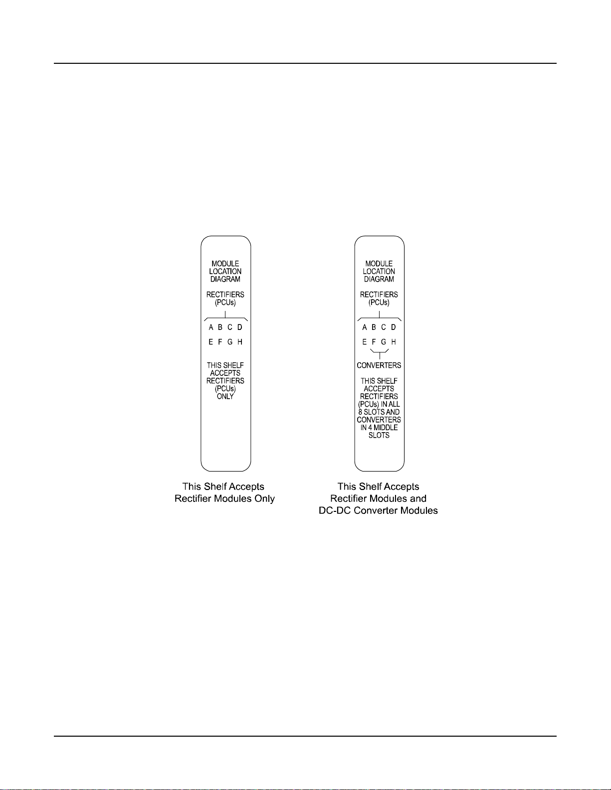
IM581127000 Installation Instructions
Issue AB, March 22, 2012 Spec. No. 581127000 (Model 710NPBA)
CHAPTER 5. INSTALLING THE MODULES AND INITIALLY STARTING THE SYSTEM
INSTALLING THE RECTIFIER AND DC-DC CONVERTER MODULES
The module location diagram on the front of each shelf shows which type modules can
be operated in that shelf. (See Figure 5-1.) Rectifiers will operate in any mounting
position in any shelf. If a shelf accepts DC-DC converter modules, they must be installed
in any or all of the four middle mounting positions.
Figure 5-1
Module Location Diagrams (on the front of each shelf)
Note: Each rectifier and DC-DC converter module locks into the module mounting
assembly by means of a latch located on the right-hand side of the module. The
latch and module handle are interactive. Pushing the handle into the module front
panel causes the latch to extend to the locking position; pulling the handle out
from the module front panel causes the latch to retract. See Figure 5-2 for handle
operation.
Warning: To prevent damage to the latching mechanism, ensure the handle is in
the open position when installing or removing a module. NEVER hold
the handle in the closed position when installing a module into a shelf.
Page 90 Chapter 5. Installing the Modules and Initially Starting the System
This document is property of Emerson Network Power, Energy Systems, North America, Inc. and contains confidential and proprietary information owned by Emerson Network Power, Energy
Systems, North America, Inc. Any copying, use, or disclosure of it without the written permission of Emerson Network Power, Energy Systems, North America, Inc. is strictly prohibited.
Page 99

Installation Instructions IM581127000
Spec. No. 581127000 (Model 710NPBA) Issue AB, March 22, 2012
Figure 5-2
Handle/Latch Operation on the Rectifier and DC-DC Converter Modules
Procedure
1) Unpack the modules.
2) Note the model number located on the handle of each module. Model numbers
starting with the letter “R” (R24-2500 or 24-3000) are rectifiers. Model numbers
starting with the letter “C” (C24/48-1500) are DC-DC converter modules.
3) Check the module location diagram on the front of the shelf to determine which
type of module (rectifier or DC-DC converter) can be installed in each mounting
position. See Figure 5-1.
4) If present, remove blank cover panels from the mounting positions into which
rectifier or DC-DC converter modules are to be installed.
5) Place the module into an unoccupied mounting slot without sliding it in
completely.
6) Loosen the captive screw on the module handle. Pull the handle to pivot it out of
the module front panel (this will also retract the latch mechanism located at the
right side of the module). See Figure 5-2.
7) Push the module completely into the shelf.
8) Push the handle into the front panel of the module. This will lock the module
securely to the shelf. Tighten the captive screw on the handle.
9) Repeat the above steps for each module being installed in the system.
10) After the modules are physically installed in the mounting shelf(s), they are ready
for operation immediately after power is supplied to them.
Chapter 5. Installing the Modules and Initially Starting the System Page 91
This document is property of Emerson Network Power, Energy Systems, North America, Inc. and contains confidential and proprietary information owned by Emerson Network Power, Energy
Systems, North America, Inc. Any copying, use, or disclosure of it without the written permission of Emerson Network Power, Energy Systems, North America, Inc. is strictly prohibited.
Page 100

IM581127000 Installation Instructions
Issue AB, March 22, 2012 Spec. No. 581127000 (Model 710NPBA)
INITIALLY STARTING, CONFIGURING, AND CHECKING SYSTEM OPERATION
Important Safety Instructions
Caution: Performing various steps in the following procedures may cause a
service interruption and/or result in the extension of alarms. Notify any
appropriate personnel before starting these procedures. Also, notify
personnel when these procedures are completed.
Initial Startup Preparation
Ensure that all blocks for Chapters 2 through 4 in the Installation Acceptance
Checklist, located in Chapter 1, have been checked.
Ensure that module mounting positions are filled by a rectifier module, DC-DC
converter module, or a blank cover panel as desired. It is acceptable for positions to
be left vacant.
Refer to the configuration drawing (C-drawing) supplied with your power system
documentation for factory settings of adjustable parameters.
Initially Starting the System
Procedure
1) Apply DC input power to the system by closing the external DC disconnect(s) or
protective device(s) that supplies battery power to the system, if furnished. Close
the system’s internal battery disconnect circuit breakers, if furnished.
2) Apply AC input power to the system by closing ALL external AC disconnects or
protective devices that supply AC power to the module mounting shelves.
Rectifiers and converters (if furnished) automatically start.
3) Open the distribution cabinet’s front door by turning the latch in the
counterclockwise position.
4) Place each distribution circuit breaker (if furnished) to the ON position.
Page 92 Chapter 5. Installing the Modules and Initially Starting the System
This document is property of Emerson Network Power, Energy Systems, North America, Inc. and contains confidential and proprietary information owned by Emerson Network Power, Energy
Systems, North America, Inc. Any copying, use, or disclosure of it without the written permission of Emerson Network Power, Energy Systems, North America, Inc. is strictly prohibited.
 Loading...