

Page 1
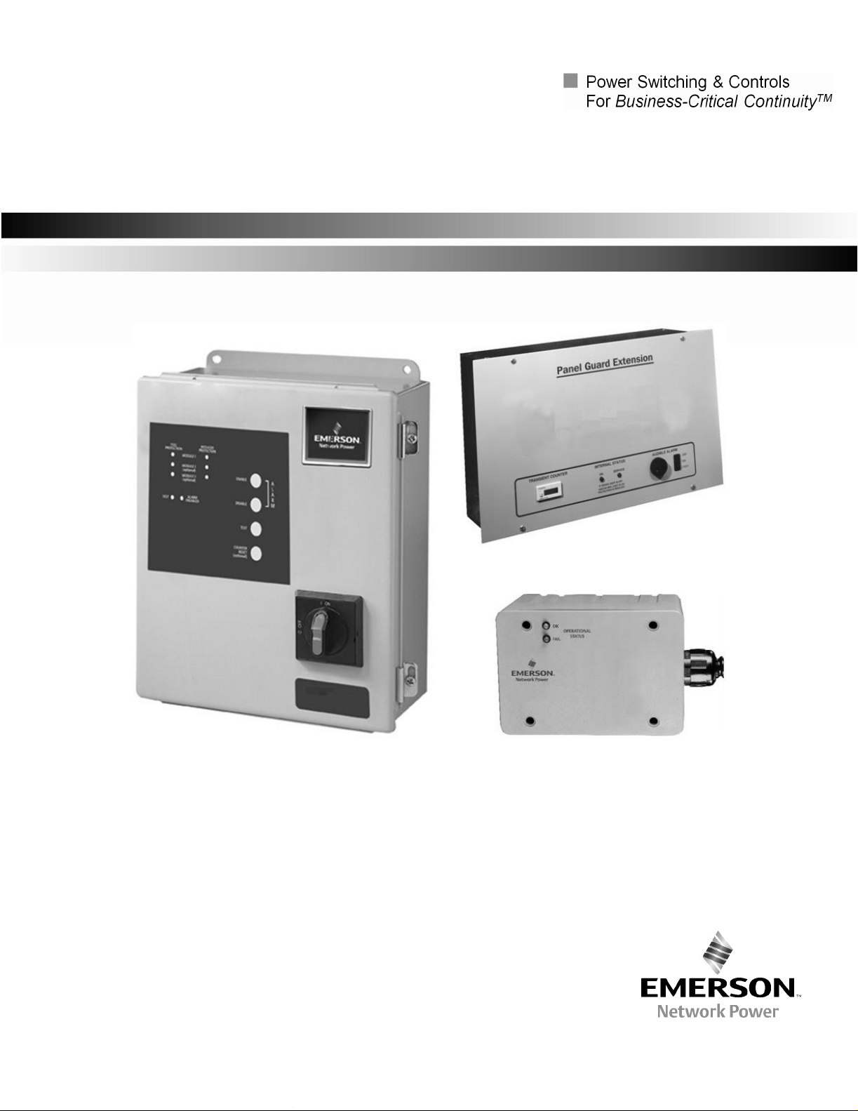
500 Series
510 Surge Protective Device
Installation, Operation and Maintenance Manual
Page 2

Surge Pr
EMERSON NETWORK POWER SURGE
DE
VICE INSTALL
ATION
, OPER
MAINTENANCE MANUAL
TAB
LE OF CONTENTS
UNPACKING AND INSTALL
Unpacking and Prelimi
H
andling Cons
St
orage. . . . . . . . . . . . . . . . . . . . . . . . . . . . . . . . . . . . . . . . . . . . . . . . . . . . . . . . . . . . . . . . . . . . . .
LOCA
TION CONSIDERATIONS
En
vironm
A
udible Noi
Service Cle
Mounting . . . . . . . . . . . . . . . . . . . . . . .. . . . . . . . . . . . . . . . . . . . . . . . . . . . . . . . . . . . . . . .
War
nings Defined . . . . . . . . . . . . . . . . . . . . . . . . . . . . . . . . . . . . . . . . . . . . . . . . . . . . . . . . . . . . . . . . . . . . . . . . . . . . . . . . . .
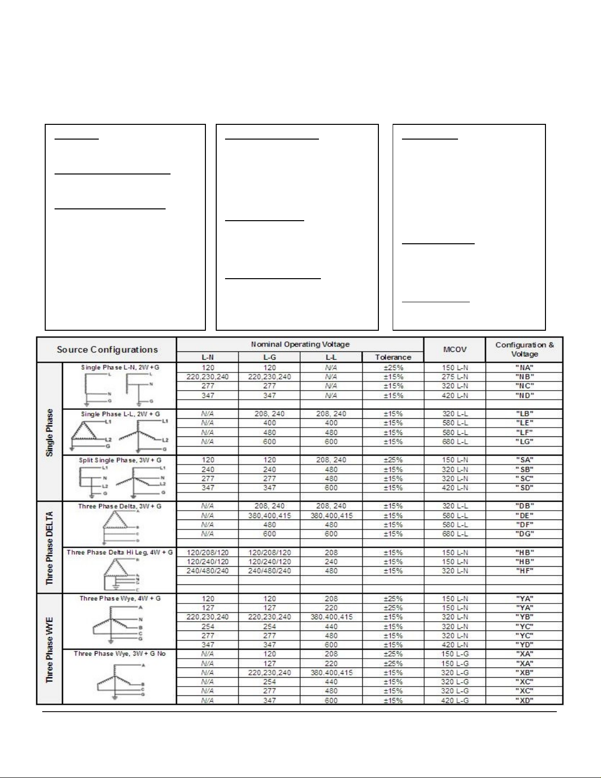
MODEL NUMBER CONFIGURATION
Model Number Configuration . . . . . . . . . . . . . . . . . . . . . . . . . .. . . . . . . . . . . . . . . . . . . . . . . . . . . . . . . . . . . . . . . . . . . . . . . .
Configuration & Voltage (Chart) . . . . . . . . . . . . . . . . . . . . . . . .. . . . . . . . . . . . . . . . . . . . . . . . . . . . . . . . . . . . . .
idera
tions . . . . . . . . . . . . . . . . . . . . . . . . . . . . . . . . . . . . . . . . . . . . . . . . . . . . . . . . . . . . .
ent
. . . . . . . . . . . . . . . . . . . . . . . . . . . . . . . . . . . . . . .. . . . . . . . . . . . . . . . . . . . . . . . . . . . . . . . . . . . . . . . . . . . . . . .
se
. . . . . . . . . . . . . . .. . . . . . . . . . . . . . . . . . . .
aran
ces
. . . . . . . . . . . . . . . . . . . . . . . . . . . . . . . . . . . . . . . . . . . . . . . . . . . . . . . . . . . . . . . . . .
ATION
nar
y Inspection . . . . . . . . . . . . . . . . . .
. . . . . .
. . . . . . . . . . . . . . . . . . . . . . . . . . . . . . . . . . . . . . . . . . . . . . . . . . .
. . . . . . . . . . . . . . . . . . . . . . . . . . . . . . . . . . . . . . . . . .
PROTEC
ATI
ON AND
TIVE
. . . . . . . . . . . . . . . . . . . . . . . . . . .
otectiv
. . . . . . . . . . . . . . . . . . . . .
e Devi
. . . . . . . . . . . . . . . .
. . . . . . . . . . . . . . .
. . . . . . . . . .
ces
2
2
2
2
2
2
2
2
3
3
ELECTRICAL CONNECTIONS
Volt
age Ratings and Power Source Configurations . . . . . . . . . . . . . . . . . . . . . . . . . . . .. . . . . . . . . . . . . . . . . . . . . . . . . . . . .
Wire Connections . . . . . . . . . . . . . . . . . . . . . . . . . . . . . . . . . . . . . . . . . . . . . . . . . . . . . . . . . . . . . . . . . . . . . . . . . . . . . . . . . .
Over Curren
NEC C
Volt
age Pr
Circuit Am
System Grounding and Bonding . . . . . . . . . . . . . . . . .
P
arallel Connections . . . . . . . . . . . . . . . . . . . . . . . . . . . . . . . . . . . . . . . . . . . . . . . . . . . . . . . . . . . . . . . . . . . . . . . . . . . . . . . .
Grounding Electrode . . . . . . . . . . . . . . . . . . . . . . . . . . . . . . . . . . . . . . . . . . . . . . . . . . . . . . . . . . . . . . . . . . . . . . . . . . . . . . . .
Ne
utral Connection . . . . . . . . . . . . . . . . . . . . . . . . . . . . . . . . . . . . . . . . . . . . . . . . . . . . . . . . . . . . . . . . . . . . . . . . . . . . . . . . .
INST
ALLATION INST
Product Installation . . . . . . . . . . . . . . . . . . . . . . . . . . . . . . . . . . . . . . . . . . . . . . . . . . . . . . . . . . . . . . . . . . . . . . . . . . . .
NEMA 12 (Metal) Enclosure Option
NEMA 4X (Non-Metallic) Enclosure Option . . . . . . . . . . . . . . . . . . . . . . . . . . . . . . . . . . . . . . . . . . . . . . . . . . . . . . . . . . . . . . .
NEMA 1 Panelboard Extension Enclosure Option . . . . . .. .
MO
NITORING FEA
Extern
A
udible A
Sum
mar
T
ransient Cou
ons
al
idera
otec
pacit
Statu
lar
y A
t Pr
otec
tion . . . . . . . . . . . . . . . . . . . . . . . . . . . . . . . . . . . . . . .. . . . . . . . . . . . . . . . . . . . . . . . . . . . . . . . . . . . . . .
tions . . . . . . . . . . . . . . . . . . . . . . . . . . . . . . . . . . . . . . . . . .. . . . . . . . . . . . . . . . . . . . .
tion Ratings . . . . . . . . . . . . . . . . . . . . . . . . . . . . . . . . . . . . . . . . . . . . . . . . . . . . . . . . . . . . . .
y Limitations . . . . . . . . . . . . . . . . . . . . . . . . . . .
RUC
TUR
ES
s Indicator
m (Stan
larm Contac
nte
dard
r (
Optional
TIONS
. . . . . . . . . . . . . . . . . .
s (Stan
/Optional
t (Stan
dard)
. . . . . . . . . . . . . . . . . . . . . . . . . . . . . . . . . . . . . . . . . . . . . . .
)
. . . . . . . . . . . .
dard
/Optional) . . . . . . . . . . . . . . . . . . . . . . . . . . . . . . . . . . . . . . . . . . . . . . . . .. . . . . . . . . . .
)
. . . . . . . . . . . . . . . . . . . .
. . . . . . . . . . . . . . . . . .
. . . . . . . . . . . . . . . . . . . . . . . . . . . . . . . . . . . . . . . . . . . . . . .
...
. . . . . . . . . . . . . . . . . . . . . . . . . . . . . . . . . . . . . . . . . . . . . .
. . . . . .
. . . . . . . . . . . .
. . . . . . . . . . . . . . . . . . . . . .
. . . . . . . . . . . . . . . . .. . . . . . . . . . . . . . . . . . . . . . . . . . . . .
.
. . . . . . . . . . . . . . . . . . . . . . . . . . . . . . . .
. . . . . . . . . . . . . . . . . . . . . . . . . .
. . . . . . . . . . . . . . . . . . . . . . . . .. . . . . . .
. . . . . . . . . . . . . . . . . . .
. . . . . . . . . . . .
. . . . .
.
. . . . .
. . . . . . . . . . . . . . . .
. . . . . . . . . . . . . . . .
4
4
4
4
4
4
4
5
5
5
6
7
7
8
9
9
9
9
TR
OUBLESHO
T
roubleshooting . . . . . . . . . . . . . . . . . . . . . . . . . . . . . . . . . . . . . . . . . . . . . . . . . . . . . . . . . . . . . . . . . . . . . . . . . . . . . . . . . . .
Servic
ing . . . . . . . . . . . . . . . . . . . . . . . . . . . . . . . . . . . .
Corrective Maintenance
Pr
eventative Maintenance
Installation,
OTI
NG/SERVICING/MAINTENANCE
. . . . . . . . . . . . . . . . . . . . . . . . . . . . . . . . . . . . . . . . . . . . . . . . . . . . . . . . . . . . . .
. . . . . . . . . . . . . . . . . . . . . . . . . . . . . . . . . . . . . . . . . . . . . . . . . . . . . . . . . . . .. . .
Opera
tion and Maintenance Manual
. . . . . . . . . . . . . . . . . . . . . . . . . . . . . . . . . . . . . . . . . . . . . . . . . . . . .
. . . . . . . . . . . . . . . . 9
. . . . . . . . . . . . .
1
IO-70103
Re
v 0, 1/2013
9
9
9
Page 3
UNPACKING AND INSTALL
Unpacking and Preliminary Inspection
1. Inspect the shipping crate(s) for
si
gns of mishandling before unpacking the unit.
2.
Remove
and inspect the unit for any obvious shipping
3. If
any dam
immediate
forward a copy to y
Surge Protection Sales Representative.
Handling Considerations
Larger
h
andling
wei
ght.
Stor
age
The unit should be stored in a
en
vironment. Storage temp
t
o +85ºC (+185ºF). Care should be
c
ondensation. All packing and shipping materi
be left i
the unit has been stored for an
unit sho
plac
ing int
any secur
age
as a re
ly file a
units are bolted
by forklift or p
Refer t
ntac
uld be
o service.
cl
o the cabinet dat
t until the unit is
cle
aned and carefully inspected
ing bands and cardb
sult
of
shipping is obs
aim with the
our local
to a
all
Emerson Network Power
shipping pall
et j
ack. Check the
a furnished with the unit.
era
ture range is -55ºC (-67ºF)
re
ady for final installation. If
exte
dam
shipping ag
et to fac
cle
an,
taken to avoid
nded period of time, the
ATION
age or
oard p
damages.
erved,
ency
ili
tate
size
and
dry
als should
bef
acking
and
ore
Surge Pr
LOCATI
F
or optimum transient surge pr
suppression should be applied at the
all other ele
CATV, etc.), at known surge g
building (
etc.), as well as at sensitive electronic loads (such as
c
ompu
etc.). For
da
ta
cabling), transi
applied
En
vironment
am
bient tempera
with a relative humidity o
The unit is pr
dust-ti
with
excessi
or explosive atmosph
A
udible Noise
than
40 dB
almost
Servi
with hinged doors on the front tha
opened. Thi
recommende
Mounting
installation inst
W
arnings Defined
ON CONSIDER
ctr
ical connections to the buildin
lar
ge motor
ter
s, electronic appliances, solid s
interc
to the interc
ovi
ght and d
ve du
at 5 feet,
an
y room if desire
ce Clearance
rty-
d.
s, arc welders, switched ca
onnected electronic
ent sur
ge suppression should also be
onnecting wiring (dat
Unit is d
tures of -40ºC (-40ºF) to +60ºC (+140ºF)
ded in an industrial use
rip-ti
st,
six in
Unit is i
ruc
tions for mounting dimensions and
esi
gned for op
f 0% to 95% (no
ght and should not be installed in areas
corrosive v
eres.
The audible noi
whi
ch
allows its
d.
s
Service cle
che
s (36 in/914 mm) minimum is
nte
nded to be wall mou
D
anger:
hazardou
avoided, will result in death or
seriou
wor
d is to be limited to the
mo
st extreme situations.
otectiv
ATI
ONS
otec
tion, coordinat
service en
enera
ting loads within the
lo
ads (su
apors, flammable materials
se of
placement
aran
t are capable of being
Indicate
s situation that, if not
s inj
ury
e Devi
trance and
g (
tele
pacitor
tat
e motor d
ch as by way of
a cables).
era
tion indoors in
n-c
ondensing).
enclo
sure, which is
the unit is les
ce is
needed for units
nted. Refer to
s an im
. This
ed surge
phone,
rive
within
wei
minently
sign
al
ces
s,
s,
s
ght.
Installation,
Opera
tion and Maintenance Manual
W
arning:
hazardou
avoided, could result in death or
seriou
C
aution:
hazardou
avoided, may result in minor or
mod
us
ed to alert against unsafe
practice
2
Indicate
s situation that, if not
s injury.
Indicate
s situation that, if not
erate injury. It may also be
s.
s a p
s a p
IO-70103
otenti
otenti
Re
v 0, 1/2013
ally
ally
Page 4
(11) Enclosure
Q
= High R
ated
(8) Modes of Protection
(1-3) Series
MODEL NUMBER CONFIGURATION
Model #: _ _ _ _ _ _ _ _ _ _ _ _ _
1 2 3 4 5 6 7 8 9 10 11 12 13
A
510
= Modular/Non-Modular MOV
(4-5) Configuration & Voltage
See Chart Below
(6-7) Surge Rating Per Mode
06
= 65kA
08
= 80kA
10
= 100kA
12
= 125kA
16 = 160kA
20
= 200kA
25
= 250kA
= All Modes of Protection
B
= L-N & N
E
= L
F
= L
G
= L
(9) Connection Type
N
= Wiring terminals/Lugs
R
= Rotary Disconnect Switch
W
= Wire
(10) Monitoring Options
R
= LED/Relay
A
= LED/Alarm/Relay
C
= LED/Alarm/Counter/Relay
-G
-L
-N
-G
Leads
R
G
H
J
L
F
S
0
1
2
(13) MOV Option
S
Surge Pr
= Type 3R (me
= Type 4 (metal)
= Type 4X (Stainless Steel)
= Type 4X (Non-Metallic)
= Type 12 (metal)
= Panelboard Flush (metal)
= Panelboard Surface (metal)
(12) UL 1449 Type
= No UL
= Type 1
= Type 2
= Standard
otectiv
tal)
e Devi
ces
Installation,
Opera
tion and Maintenance Manual
3
IO-70103
Re
v 0, 1/2013
Page 5

ELECTRICAL CONN
All ele
ctr
ical connections should be installed by a qualified
(li
cens
ed) ele
ctrici
an only. All wiring must comply with the
Na
tional Ele
codes.
DE-
ENE
Volt
age Ratings and
Bef
ore making connections to the unit,
model numb
appropriate for connection to the i
See the
with
typ
Wire Con
the wiring
circuit s ampacity
suppr
c
opper
to surge curren
ne
utral (if required), and ground condu
together
an
y s
Overc
practically no
c
onducts
NEC C
Ele
ctr
NEC 285.21 Con
NEC
accordance
(A) Installation. Type 1 SPD
f
oll
ows:
(1)
the
per
230.82(4) or
(B) At the service. Whe
grounding conductor of a Type 1 SPD shall be connected
t
o one of the followin
ctr
ical Code (NEC)
VERIFY THAT ALL POWER C
RGI
ZED AND LOCKED OUT BEFORE MAKING
ELECTRICAL CONNECTION
Pow
er
and nameplate voltage rating are
char
t on page
ical power s
nec
tions
to
the SPD unit is ind
ess
or connecting condu
or #12 aluminum.
ts, it is recommended t
and routed in the same raceway (conduit).
har
p bends in the condu
urrent Protec
curren
ver
y short duration transient surge
onsiderations
ic Code 2008 Edition.
285.23 Type
with 285.35(A) and (B).
Type 1 SPDs sh
supply
side of
mitted in
(2) Type
c
onnected in Type 2 locations as spec
1 SPDs sh
3 f
ource configurations.
With parallel connection, the size of
. NEC Article 285-21(B) requires surge
tion
t under normal op
-
The following is from the National
nec
tions
1 SPD s. Sh
all be
the
n installed at the
g:
and applicable local
IRCU
ITS ARE
S.
er Source Configurations
verif
nte
nded power s
or voltage rating applications
ependent of
ctors t
o be at least #14
To
redu
ce
the wiring impedan
hat
the phase
ctors
ctors.
The SPD unit conducts
era
tion
all be installed in
s shall be installed as
per
mitted
to be c
service disc
all be
per
onne
mitted
to be
service
y that the unit
ource.
the pr
otected
,
are twisted
Avoi
and only
curren
ts.
onnected to
ct as
ified in 285.24.
s, the
Surge Pr
ECTI
ONS
(1) Grounded
(2) Grounded electrode conductor
(3) Grounding electrode for
(4)Equipm
Volt
age Protec
pr
otec
tion ratings (VPR
L
aboratory
for Saf
ety
Third Edition
wire size listed for
the unit to your
c
ondu
ctors othe
differen
Circuit
these products
L
live circuits or components at system voltages and fault
curren
Saf
Third Edition
Syst
safety o
and bonding. Grounding is required for s
ce
impl
In
op
d
All ele
UNGROUNDED POWER SYSTEMS ARE INHERENTLY
UNSTABLE AND CAN
LINE-TO- GR
C
ELECTRICAL EQUIPMENT, INCLUDING AN SPD, MAY BE
SU
DESIG
PROVI
DE
ELECTRICAL EQUIPMENT ON AN UNGROUNDED
PO
UNGROUNDED APPLICATION
An insulated
met
F
be the same wire
c
t VPRs.
Ampacity Limitations
aboratorie
ts up to 200,000 AIC, as descr
ety
, Surge Pr
em Grounding and Bonding
f any SPD system is d
ementa
correc
t grounding can reduce or impede the
era
tion.
ctr
ical circuits to the SPD must include an equipm
ONDITIONS. DURING THESE
BJEC
TED TO
NED R
DED TO THE USER SO THAT AN
CISION CAN BE MADE BEFORE INSTALLING ANY
WER SYSTEM. CON
allic racew
or parall
ondu
el-c
ctors.
service c
ent
grounding
tion Ratings
, In
cor
por
, Surge Pr
, released (2009), mark
eac
fac
iliti
r than the wire
hav
s, In
cor
otectiv
, released (2009).
tion also
OUND
VOLTAGES W
ATINGS
grounding conductor is required in addition
ay,
whi
onnected SPDs, the grounding conductor should
size as
onductor
s), as obtained by Und
ated
, in accordanc
otectiv
e Dev
h product must be utilized to connect
es
power grid. C
e been investigat
porated to withstand, without exposing
e Dev
enhance
PRODUCE EXCESSIVE
VOLTAGES DURING CER
. THIS
TACT FACTORY F
ch may be used as a
otectiv
service
terminal in
T
o obtain the voltage
ice
s (
siz
e listed may result in
Repres
ice
s (
SPD
ependent
s equipment p
gro
unding conductor as
required by the NEC and local
codes.
FAULT C
HICH E
INF
ORMATION IS BEING
S.
the associated pow
e Devi
the
service
erwriter
e with the Standard
SPD
s), Standar
ed on this product, the
onnections made with
entative samples of
ed by Und
ibed in the Standar
s), Standar
The p
erwriter
erformanc
on proper grounding
afety. Correc
erformance
SPDs
ONDITIONS ANY
XCEED THEIR
INF
ORMED
OR
grounding condu
ces
equipm
LY HIGH
TAIN FAUL
er
ent
s
d 1449,
s
d for
d 1449,
e and
t
.
ent-
to an
ctor
T
y
.
Installation,
Opera
tion and Maintenance Manual
4
IO-70103
Re
v 0, 1/2013
Page 6

d
(with
Ground
Protected
Panel
T
ypical
out Internal
Neutral
Phases
Par
allel Con
Wire should be
less than 5
and straigh
as pos
sibl
Rotar
feet
t
e
nec
tions
y Discon
Ne
utra
l
Phase(s
)
T
ransient
Groun
d
S
afety
Groun
d
P
ARALLEL CONN
nect)
T
o
Protect
Lo
ads
Surge
Protectiv
e
Device
ed
Surge Pr
ECTI
ONS
T
ypical
(with Internal
Groun
Protected
Phases
Panel
Neutral
Par
allel Con
Wire shoul
less than 5 feet
and straigh
as possibl
Rotar
d be
t
e
otectiv
nec
y Discon
Rotary
Disconne
ct
e Devi
tions
nect)
Ne
utra
l
Pha
se(s
T
ransient
Groun
d
S
afety
Groun
d
ces
T
o
Protect
ed
Lo
ads
Surge
Protectiv
Device
e
)
Grounding condu
power c
met
mu
raceway
The
met
recommende
G
dischar
device
to c
In the case of lightning whose p
respec
t
o the grounding electrode (
mo
lo
without involving the grounding electrod
ondu
allic raceways are
st be maintai
termina
use o
allic conduit run is a p
rounding Electrode
ge all su
s can also di
omplete the ele
t to th
st transient su
ads, the SPD di
ctors mu
ctor
s in the same raceway (conduit). When
ned at all raceway connections,
tions to the ele
f isola
ting bushings or other means to i
d.
rges t
e
ear
rge
ver
st be routed with the associated
used
, adequate electr
ctr
ical
enclo
otenti
al s
afety hazar
Surge pr
o ground (
ver
t the surge
ctr
ical circuit.
th, the SPD di
ear
s that are d
ts the surge
otectiv
ear
th). Surge pr
curren
otenti
al is d
ver
th connection). H
eve
loped by switching
curren
ical
con
tinuity
particular
sures.
nterrup
d and is not
e devices do not
otectiv
e
t back to its source
eve
loped with
ts the surge
t back to its source
e.
owe
curren
ver, f
F
or proper SPD p
grounding electrode system must comply with the NEC by
ha
ving all available electrodes (building s
ly
pipe
, d
rive
n rods, concrete encased electrodes, etc.)
properly bonded togeth
syste
t a
t
or
m grounding.
The use of a
S
PD defeats the
hazard, ma
(refe
renc
e NEC 250-51 and 250-54), and is not
recommende
Neutr
al Con
C
ONNECTED
FAIL
URE TO PROVIDE A RELIABLE NEUTRAL
C
ONNECTION MAY R
erformance
er
and connected to the powe
separat
y cause equipment
d.
nec
e grounding electrode to ground the
effectiveness of
tion
TO THE NEU
TRAL OF THE
ESUL
T IN FAILURE!
, the
service en
tee
the
SPD, is a potential safety
damage
F
OR PROPER AND
OPERATION, THE
NEUTRAL, MUST BE
RELIAB
, is an NEC violation
LY
trance
l, metal
SOUR
wate
r
SAFE
SPDs
CE.
r
Installation,
Opera
tion and Maintenance Manual
5
IO-70103
Re
v 0, 1/2013
Page 7

v 0, 1/2013
INST
ALL
ATI
The Emerson Network Power
Device
s (SPDs) are high quality, high
di
ver
sion systems d
from
dam
aging transient voltage su
is required for maximum system p
The installer should p
qu
ality installation. The entire installation manual should be
re
ad before s
replace na
electr
system
1.
Insure that all powe
installation.
electr
2. The standard SPD is pr
NEMA12 (indoor) or NEMA 4X (outdoor)
suitable for use in indoor or outdoor installations. Verify
the SPD enclosure rating by referencing
Model Number Configuration tool on page 3.
tional or local ele
ical cod
should only be
A qu
ical connections.
esi
erfor
tar
ting installation. These inst
es to e
nsure complian
r is remov
alified li
510 Serie
gned to pr
m the following s
ctr
ical codes. Chec
perfor
med
ed before beginning
censed electrician sh
ovi
ded in a
s Surge Pr
ener
otect se
rge
s. Proper installation
erformance.
ce.
Installation
by qu
alified p
NEMA 1 (indoor),
otectiv
gy surge
nsitive equipment
teps to as
ruc
rated
position 11 in
curren
sure a
tions do not
k applicable
of
the SPD
ers
onnel.
all install all
enclo
sur
ON INST
e
t
es
the
Surge Pr
RUCTI
6. Apply power
when the
the fro
LED s are ex
to e
indication is present, remove power t
Em
ers
6169 or 1-607-721-8840
7.
Per
pr
otec
the RED LED is illuminated
Networ
6169 or
8.
The pr
replace
Pr
otec
ONS
. The surge pr
GR
EEN
LED s on
nt of
the
enclo
sure are illuminated
tinguished or a RED LED is illuminated, c
nsure tha
on N
iodically monitor the s
tion exists if the
tion for r
t power is
etwork Powe
k Power Surge Pr
1-
607-721-8840.
otec
tion modules in these
able,
contac
t Em
eplacement.
GREEN LED s are ex
otectiv
otect
or is fully op
the
modul
applied to the
r Surge Pr
.
. Pl
ers
on N
otec
tatus of the LED s. R
ease contac
otec
tion at
etwork Powe
e Devi
es
(when applicable),
. If the GREEN
SPD. If an
o the SPD and
tion at 1-800-288
SPD s may be
ces
era
educed
tinguished or
t Em
ers
1-
800-288
r Surge
tional
heck
abnormal
contac
on
-
and
-
t
3.
Deter
mine where the SPD is to be mou
f
or minimum length of wire b
power termin
proper hole size in the
knockout to be utilized in the
plastic enclosure units include a flexible conduit/nipple
accessory
mounting holes in wall at location picked for SPD next to
service panel us
t
able
below.
appropriate size & type mounting
4. Connect black wires (line or phas
L3/C, the white wire (neutral)
(grou
nd)
below. T
electr
ical distribution system,
a
s possible and avoi
5. Connection
with #18
are 5 amps at 250 VAC maximum with a power fact
1.0. For additional i
als of the
no punching/drilling required in SPD) Drill
ing mounting dimensions shown in the
Mou
nt surge
mark
ed G, of the SPD using the wire range listed
o yield the best p
d s
to the unit s summar
22
AWG.
nformation,
etwee
service pane
si
de of the SPD
service pane
suppr
ess
mark
erformance o
kee
har
p bends.
The
ra
tin
gs of
see Monitoring sec
n itself and the input
hardware.
p all condu
nted
, allowing
l. Punch or cut the
closest
l.
or to wall using
e)
mark
ed L1/A, L2/B or
ed N, and the green wire
f the SPD within the
y a
larm contac
the
Form C
t
o the
(NEMA 4X
ctors a
s short
ts shall be
contacts
or of
tion.
If
the SPD
and a Neutral con
contact factory.
model is
nec
a Wye c
tion is not available, please
onfi
gured unit (4W+G),
Installation,
Opera
tion and Maintenance Manual
6
IO-70103
Re
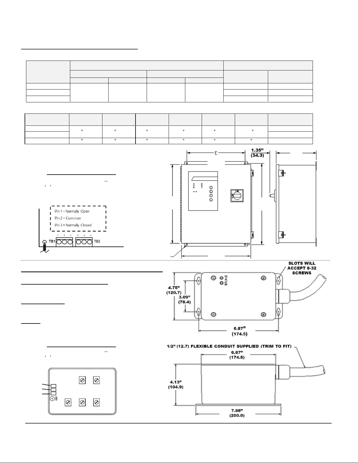
Page 8
v 0, 1/2013
Surge Rating
CircuitBreake
r
Siz
e
Allowable Range
Allowable Range: #14
NC
COM
NO
A
C
B
E
D
F
NEMA 12 (Metal) Enclosure Option
SUGGE
DIMENSIONAL INFORMATION
STED CIRCUIT
Surge Rating
Per Mode
60kA-80kA
100kA-160kA
200kA-250kA
Per Mode
60kA-80kA
100kA-160kA
200kA-250kA
C
onnection shall be with #18
Form C
250 VAC max.
20 (508) 16 (406) 9 (229) 21.3 (540) 10 (254) 0.44 (11)
Summary Alarm Contacts
contacts
BRE
With Disconne
40A-150A
A B C D E F
16 (406) 14 (356) 8 (203) 16.8 (426) 12 (305) 0.31
are rated
AKER AND WIRE SIZE
Allowable R
ct
Without Disconne
15A-100A
22
AWG.
5 amps at
ct
ange
Connec
With Disconne
#8-1/O
tion Wire Size
ct
Without Disconne
#14-#2
Surge Pr
Factory
Circuit Br
ct
Size
40 Amp
40 Amp
100 Amp
Sugg
eaker
(8)
otectiv
ested Size
Connec
32 lb. (14.5 kg)
41 lb. (18.6 kg)
56 lb. (25.4 kg)
e Devi
tion
Wire Size
#8 AWG
#8 AWG
#2 AWG
Weight
ces
(Located on PCB behind monitoring panel)
NEMA 4X (
Overcurrent Prot
Connection Wire
Weight:
6.5 lb. (3 kg)
C
onnection shall be with #18
Form C
250 VAC max.
Installation,
Non-Metallic
ection (Circuit Breaker)
: 15A - 30A
:
Summary Alarm Contacts
contacts
Shown with cover removed
Opera
tion and Maintenance Manual
-
#10
are rated
) Enclosure Option
:
Suggested Size: 30A
Suggested Size: #10
22
AWG.
5 amps at
7
IO-70103
Re
Page 9

v 0, 1/2013
Allowable Range
Allowable Range: #14
Surge
-
ard Extension
Customer Supplied
Panelboard
ACBED
F
(SURFACE)
G
(FLUSH)
NO
NEMA
SUGGE
1 Panelboard Extension Enclosure
STED CIRCUIT
Overcurrent Protection (Circuit Breaker)
: 15A - 100A Suggested Size: 30A
Connection Wire
Weight:
30 lb. (13.6 kg)
Summary Alarm Contacts
Co
nnection shall be with #18
Form C
250 VAC max.
:
contacts
BRE
- #2
are rated
AKER AND WIRE SIZE
Suggested Size: #10
5 amps at
:
22
AWG.
COM
NC
Surge Pr
Option
otectiv
e Devi
ces
Shown with
DIMENSIONAL INFORMATION
A B C D E F G
18
(457)
12
(305)
module
6
(152)
cover removed
11
(279)
15
(
381)
20.25
(514)
21.5
(546)
(
REMOVE COVER
FOR ACCESS
)
Installation,
Opera
tion and Maintenance Manual
8
510
Protective Device
Panelbo
IO-70103
Re
Page 10

v 0, 1/2013
MONITORI
Ext
ernal
Stat
us Indica
pr
ovide a
module. For normal conditions, the green
illuminat
surge SPD or
LED is turned off and the red
A
udible Alarm
module requires r
activat
required to r
audible a
syste
alarm switch and
the Test switc
Summa
two sets of
N.C.) are pr
SPD
m
aximum with
contacts is provi
the unit s cover.
Surge Counter (Optional
f
or transient voltage surge moni
line su
rese
sine wave. The
voltage. Other se
T
roubleshootin
If s
tatus f
have ch
deter
If the SPD
electrici
c
onnections are normal, the unit should be repaire
At
this poi
f
ollowing i
sum
mary of
ed and the red
module requires r
(St
andard
eplacemen
ed to draw
lar
m will automa
ry
modul
rge
s monitored since the last time the cou
t. The circuit counts all su
SERVICING/ MAINTENANCE
ailure indication oc
anged state
mine if the systems voltage and proper phasing exists.
rem
an is
nt c
nformatio
atten
est
ore the system to normal op
m disable is pr
tically rese
Service
h on the system monitor panel.
Alarm Con
sum
mar
y a
ovi
ded for
e. Contac
a power factor of
ded
factory se
ttings include 50%, 70%, and 100%.
TROUBLESHOOTIN
g
ains in an
sa
tisfied that
onsult the
n:
NG FEATUR
tor
s (Standard)
the
status of
Service
tion to the
tact (St
larm For
remote
ts are
via contact termin
tting is 30% ove
, a qualified ele
alarm c
factory, having
LED is
eplacemen
Service
/Optional
t, an audible a
fact that repair
ovi
ded to sil
t itself
LED can be test
andard
m C relay contac
indication
rated 5 amps at
1.0.
)
The surge cou
tor
ing. The cou
rge
s that deviate from the line
cur
s or sum
ctrici
ond
the ele
ctr
ES
These indicator
the surge SPD
OK LED is
ex
tinguishe
t, the green
LED illuminated.
)
If the surge SPD
larm may be
era
tion. An
enc
e the a
after repair.
ed by activating
/Optional
of
the failed surge
250
Access to
als located inside of
nter
nter total
r nominal line
G/
mar
y a
larm contac
an shall first
ition on
ical sys
avail
ce
tem
able the
d. If
the
OK
servic
e is
lar
m. The
The audible
)
One or
ts (N.O
. and
VAC
the
is provi
nter wa
the
and its
ded
ize
s
d.
Surge Pr
Servicing
s
The Emerson Network Power 5
ten year warrant
local Sales Representativ
Surge Pr
ONLY QUAL
MAINTENANCE ON THE SYSTE
HAZARDOUS
UNIT DURI
ELECTRICAL SAFETY
FOLLO
TO PRE
OFF AND LOCK OUT ALL POWER SOU
UN
C
orrective Maintenance - The
51
0 Series SPD is d
op
era
f
ail under abnormal conditions. Diagnostic indicator
pr
ovi
s
replacemen
f
ailed units should be repaired or r
convenient service
modules, other components should be inspected for
dam
troubleshooting procedur
problems oth
When r
c
omponents for
Pl
ease contact factory f
ts
Preventative Maintenance (Inspection and
Per
c
hecks are recommended to ensure r
performanc
It is
maintenance
Inspections for failed surge modules using available
di
agnostics should be done routinely (
y. For
servic
otec
tion at
800-288-6169 or 607-721-8840.
IFI
ED
PER
SONNEL SHOULD PERFORM
VOLTAGES ARE
NG NORMAL OPERATION
PRE-CA
WED WHEN SERVICING THIS U
VENT RISK OF ELECTRICAL SHOCK, TURN
IT BEFORE SERVICING U
esi
gned for
tion. H
owe
ver, eve
ded to indicate when the unit needs repair or
t. To ensure
age and r
iodic system inspections,
di
fficult
eplac
er than f
eplac
ing components, use
con
e and
to est
sin
ce c
n the most r
opportuni
ed if necessary. Standard electr
es
ailed surge
tinued proper op
or i
con
tinued surge transient pr
ablish
a sch
onditions
otectiv
10 Series comes
ing assistance,
e or Em
con
ers
on N
M.
PRE
SENT INSIDE THE
UTIONS MUST BE
NIT.
Emerson Net
years o
eli
able equipment may
tinuity of surge pr
eplac
ty. When replac
should be
nformation on r
cle
edule for pr
vary
used to isolate
curren
t di
iden
tically rated
era
aning, and connection
eli
from si
wee
S.
f trouble-free
ed at the
tion and s
able system
e Devi
etwork Power
NIT.
RCES T
verte
eplacement par
eventativ
te to site.
kly or monthly).
ces
with
contact y
O THE
work Power
s are
otec
tion,
earliest
ing surge
ical
r modules.
afety
Cle
aning)
otec
tion.
e
a
our
,
.
ts.
-
Unit
iden
tification numb
seri
al numbers detailed on the data labe
located on the front of the
Na
ture of problem
indicator
Installation,
s and a
Opera
tion and Maintenance Manual
(including s
lar
ms).
er
(refe
enclo
rs to
sure.)
tatus o
the
l and is
f all s
mod
tatu
el
and
s
9
IO-70103
Re
Page 11

v 0, 1/2013
Surge Pr
otectiv
e Devi
ces
Installation,
Opera
tion and Maintenance Manual
10
IO-70103
Re
Page 12
v 0, 1/2013
Surge Pr
otectiv
Emerson Network Power
100 Emerson Parkway
Binghamton, NY 1
800
288 6169 Phone (U.S. & Canada Only)
607 721 8840 (Outside U.S.)
607 722 8713 FAX
United States of America
Emerson Network Power
European Headquarters
Via Leonar
Zon
35028 Piove Di Sacco (PD)
It
aly
39 049 9719 111 Phone
39 049 5841 257 FAX
do Da Vinci 8
a Industriale Tog
3905
nana
e Devi
ces
Em
ers
on N
29/F,
F. Ortigas Jr. Road, Ortigas Center
Pasig City 1605
Philippines
+63 2 687 6615
+63 2 730 9572 FAX
Technical Support
800 288 6169 Tol
607 721 8840 Phone
6
07 722 8713 FAX
© 2012 Emerson Network Power.
the world. Specifications subject to change without noti
IO-70103
etwork Power
The Orient Square Building
l-F
Rev 0,
(1/2013
ree
)
Asia Pac
All rights r
ific
eserv
ed throughout
Printed in
ce.
USA
Installation,
Opera
tion and Maintenance Manual
11
IO-70103
Re
 Loading...