

Page 1
Model 5081T-FF/FI
Instruction Sheet
PN 51A-5081T-FF/FI/rev.A
November 2005
Your purchase from Rosemount Analytical, Inc. has resulted in one of the finest instruments available for your particular application. These instruments have been
designed, and tested to meet many national and international standards. Experience indicates that its performance is directly related to the quality of the installation and
knowledge of the user in operating and maintaining the
instrument. To ensure their continued operation to the
design specifications, personnel should read this manual
thoroughly before proceeding with installation, commissioning, operation, and maintenance of this instrument. If
this equipment is used in a manner not specified by the
manufacturer, the protection provided by it against hazards may be impaired.
• Failure to follow the proper instructions may cause any
one of the following situations to occur: Loss of life; personal injury; property damage; damage to this instrument; and warranty invalidation.
• Ensure that you have received the correct model and
options from your purchase order. Verify that this manual covers your model and options. If not, call 1-800854-8257 or 949-757-8500 to request correct manual.
• For clarification of instructions, contact your Rosemount
representative.
• Follow all warnings, cautions, and instructions marked
on and supplied with the product.
• Use only qualified personnel to install, operate, update,
program and maintain the product.
• Educate your personnel in the proper installation, operation, and maintenance of the product.
• Install equipment as specified in the Installation section
of this manual. Follow appropriate local and national
codes. Only connect the product to electrical and pressure sources specified in this manual.
• Use only factory documented components for repair.
Tampering or unauthorized substitution of parts and
procedures can affect the performance and cause
unsafe operation of your process.
• All equipment doors must be closed and protective covers must be in place unless qualified personnel are performing maintenance.
• If this equipment is used in a manner not specified by
the manufacturer, the protection provided by it against
hazards may be impaired.
ESSENTIAL INSTRUCTIONS
READ THIS P
AGE BEFORE PROCEEDING!
WARNING
To prevent ignition of flammable or combustible
atmospheres, disconnect power before servicing
or understand and adhere to the manufacturer's
live maintenance procedures.
W
ARNING
Substitution of components may impair Intrinsic
Safety or suitability for Division 2.
WARNING
Do not remove or replace while circuit is live
unless area is known to be non-hazardous.
WARNING
Explosion Hazard - Do not disconnect equipment
unless area is known to be non-hazardous.
For additional information, please refer to the Instruction Manuals CD shipped with this
product, or visit our website at www.emersonprocess.com/raihome/liquid/.
FOUNDATION Fieldbus®Two-Wire
Conductivity Transmitter
Page 2
PHYSICAL SPECIFICATIONS
HOUSING: Epoxy-polyester painted over low-copper alu-
minum. Neoprene O-rings on cover. 160.5 mm x 175.3
mm x 161.3 mm (6.3 in. x 6.9 in. x 6.4 in.)
DIAMETER: 155.4 mm (6.1 in.)
ELECTRICAL CONDUIT OPENINGS: 3/4 in. FNPT
POWER SUPPLY AND LOAD: A power supply voltage of
9 Vdc to 32 Vdc at 22 mA is required; Intrinsically Safe
installations may be limited to a maximum of 2-3
transmitters per node, depending on the barrier used.
LOCAL READOUT:
Main Display is 4 digits, 20 mm tall (0.8 in.)
Message Display is ten digits, 7 mm tall (0.3 in.)
AUTOMATIC TEMPERATURE COMPENSATION:
3-wire Pt100 RTD
Conductivity: 0 to 200 °C (32 to 392 °F)
% concentration: 0 to 100 °C (32 to 212°F)
AMBIENT TEMPERATURE: -20 to 65° C (-4 to 149° F)
RELATIVE HUMIDITY: 0-95% with enclosure sealed.
CE: EMI/RFI certified: EN61326-1
HAZARDOUS AREA CLASSIFICATION:
Intrinsic Safety:
Class I, II, III, Div. 1
Groups A-G
T4 Tamb = 70°C
Exia Entity
Class I, Groups A-D
Class II, Groups E-G
Class III
T4 Tamb = 70°C
ATEX 0600
II 1 G
Baseefa03ATEX0399
EEx ia IIC T4
Tamb = -20°C to +65°C
Non-Incendive:
Class I, Div. 2, Groups A-D
Dust Ignition Proof
Class II & III, Div. 1, Groups E-G
NEMA 4X Enclosure
Class I, Div. 2, Groups A-D
Suitable for Class II, Div. 2, Groups E-G
T4 Tamb = 70°C
Explosion-Proof:
Class I, Div. 1, Groups B-D
Class II, Div. 1, Groups E-G
Class III, Div. 1
Class I, Groups B-D
Class II, Groups E-G
Class III
Tamb = 65°C max
TRANSMITTER SPECIFICATIONS @ 25°C
MEASURED RANGE*: 50 to 2,000,000 µS/cm (see chart)
ACCURACY: ± 1.0% of reading
REPEATABILITY: ± 0.25% of reading
STABILITY: 0.25% of output range/month, non-cumulative
AMBIENT TEMPERATURE COEFFICIENT: ± 0.2% of FS/°C
COMPATIBLE RTD: 100Ω with Automatic Recognition
TEMPERATURE SLOPE ADJUSTMENT: 0-5%/° C
% CONCENTRATION RANGES:
Sodium Hydroxide: 0 to 15%
Hydrochloric Acid: 0 to 16%
Sulfuric Acid: 0 to 25% and 96 to 99.7%
LOOP SPECIFICATIONS
LOOP ACCURACY: With a standard Model 228 or 225
sensor with 20' cable, laboratory accuracy at 25°C can
be as good as ±2% of reading and ±50 µS/cm.
To achieve optimum performance, standardize the sen-
sor in the process at the conductivity and temperature
of interest.
Results under real process conditions, at different tem-
peratures, or using other sensors may differ from above.
RTD ACCURACY: Utilizing a perfect 100 Ohm RTD after
1 point temperature standardiztion, temperature reading can be as good as ±0.5°C.
RECOMMENDED SENSORS:
Model 222 Flow-Through
Model 225 Clean-In-Place (CIP)
Model 226 Submersion/Insertion
Model 228 Submersion/Insertion/Retractable
Model 242 Flow-Through*
* Model 242-06 or 242-08 with 5081T do not have Intrinsically Safe
approvals.
MODEL 5081T-FF/FI SPECIFICATIONS
2
NOTE: Values shown are for 25°C conductivity with a temperature slope of 2% per degree C. The maximum range
value will be lower for solutions with a higher temperature slope. Minimum conductivity depends on sensor.
RECOMMENDED RANGES FOR TOROIDAL SENSORS
Conductivity Sensor
Model Number 226 228 225 222 (1in.) 222 (2 in.) 242
Nominal Cell Constant 1.0 3.0 3.0 6.0 4.0 *
Minimum Conductivity (µµS/cm) 50 200 200 500 500 100*
Maximum Conductivity (µµS/cm) 1,000,000 2,000,000 2,000,000 2,000,000 2,000,000 2,000,000*
* Model 242 values depend on sensor configuration and wiring.
Page 3
33
MODEL 5081T-FF/FI SPECIFICATIONS
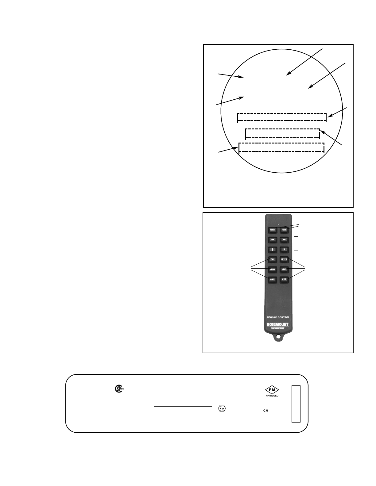
TRANSMITTER DISPLAY DURING
CALIBRATION AND PROGRAMMING
(FIGURE 1)
1. Continuous display of conductivity, % concentration,
or custom reading.
2. Units: µS/cm, mS/cm, ppm, %, or none.
3. Current menu appears here.
4. Submenus, prompts, and diagnostic readings appear
hear.
5. Commands available in each submenu or at each
prompt appear here.
6. Hold appears when the transmitter is in hold.
7. Fault appears when the transmitter detects a sensor
or instrument fault.
INFRARED REMOTE CONTROLLER
(FIGURE 2)
1. Pressing a menu key allows the user access to calibrate,
program, or diagnostic menus.
2. Press ENTER to store data and settings. Press NEXT
to move from one submenu to the next. Press EXIT to
leave without storing changes.
3. Use the editing keys to scroll through lists of allowed
settings or to change a numerical setting to the desired
value.
4. Pressing HOLD puts the transmitter in hold. Pressing
RESET causes the transmitter to abandon the present
operation and return to the main display.
FIGURE 2. INFRARED REMOTE CONTROLLER
1.
4.
3.
2.
CALIBRATE PROGRAM DIAGNOSE
/-[5ES-U1
EXIT NEXT ENTER
mS
F
A
U
L
T
H
O
L
D
6
7
3
4
1
2
5
FIGURE 1. TRANSMITTER DISPLAY DURING
CALIBRATION AND PROGRAMMING
The program display screen allows access to
calibration and programming menus.
#'"
REMOTE CONTROL
INTRINSICALLY SAFE EQUIPMENT
HAZARDOUS AREA LOCATIONS:
CLASS I, DIV 1, GP A, B, C, D
CLASS I, DIV 2, GP A, B, C, D
T3C Tamb = 40°C T3 Tamb = 80°C
1.5Vdc AAA BATTERIES
EVEREADY E92/1212
DURACELL MN2400/PC2400
IS/I/1/A,B,C & D
NI/I/2/A,B,C & D
T4 Tamb = 40°C
T3A Tamb = 80°C
Baseefa02ATEX0198
II 1G EExia IIC T4 1180
1.5Vdc AAA BATTERIES
EVEREADY E92/1212
DURACELL MN2400/PC2400
ROSEMOUNT ANALYTICAL 92606 USA
WARNING:
TO PREVENT IGNITION
CHANGE BATTERIES IN
A NONHAZARDOUS AREA
ONLY
IRC - INFRARED REMOTE CONTROL
LR 34186
Exia
SUBSTITUTION OF
COMPONENTS MAY
IMPAIR INTRINSIC SAFETY
PN 23572-00
YEAR
Page 4

4
U17:!<[9:1
-E< /!
922<U
'"*#\=\22
/1[[!/9P<U
<Q2U
4-SG
U<[9:1
2D>[=T
'"""
25.0C 12.00mA
CAL key
PROG key
DIAG key
HOLD key
Model 5081T-FF/FI
Process Display Screen
µS/cm
/-[5ES-U1
/1[[!/9P<U
<1P<9S!"
U17:!-G6
U17:
G5<:[-A
<1U>:!/V<=
G12->[=
PROGRAM
Process Display
FIGURE 1. Menu Tree
MODEL 5081T-FF/FI MENU TREE
PROGRAM MENU MNEMONICS
4Q[G
Transmitter on hold
2->[U
Fault condition current output setting
U1
7
:
Temperature menu header
U->U9
Automatic temperature compensation
U
7
-P
Manual temperature compensation input
G5<:[-A
Display menu header
UA:
Conductivity measurement type
U1
7
:!
°C / °F toggle selection
/9G1
Security code
922<U
Conductance Offset value
CALIBRATION
DIAGNOSTICS
Page 5

MODEL 5081T-FF/FI DEFAULT SETTINGS
VARIABLE NAME MNEMONIC FACTORY SETTINGS CUSTOMER SETTINGS
Program Menu
Temperature
UHOR
Auto temperature compensation UDVUQ on ___________
Manual temperature UODP 25.0°C (overridden by auto) ___________
Temperature compensation algorithm /97: ([LPHDS or P9P1) LInEAr ___________
Display
GLTRNDY
Measurement type UYR (/QPG>/ or P-94 or 4/[ CondUC ___________
or 4$<9&[ or 4$<9&4 or /VTU)
Temperature (°C or °F) UHOR C ___________
Output (mA or %) QVURVU Cur ___________
Security Code FQGH 000 ___________
Custom Curve
<1U>:!!/V<U
___________
Reference temperature U!SHI 25.0°C ___________
Calibrate Menu
Cell constant /1[[!/QPTU 3.00 ___________
Temperature slope U17:!TN9RH 2.000 ___________
Diagnose Menu
Diagnose SAMPLE READINGS
(Each segment displays the current value in the transmitter.)
Absolute conductivity -ET 1000 µS ___________
Off Set 9II<U 0.0 µS ___________
Cell constant /1[[!/9P<U 3.00/cm ___________
Temperature slope UTNQRH 2.000 ___________
Software version TQIU A02.09 ___________
Hardware version 4-SG 01 ___________
Show fault warnings 2D>[=< none ___________
5
Page 6
6
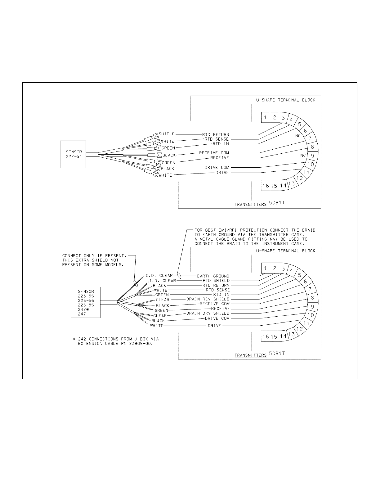
MODEL 5081T-FF/FI WIRING
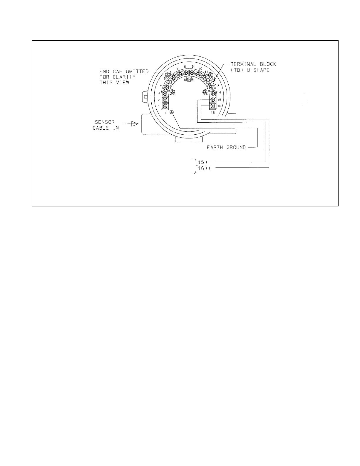
WIRING
Wire sensor as shown below in Figure 2. Keep sensor wiring separate from power wiring. For best EMI/RFI protection, use
shielded output signal cable in an earth-grounded metal conduit. Refer to the sensor instruction manual for more details.
FIGURE 2. Wiring Model 5081T-FF/FI
Page 7
77
MODEL 5081T-FF/FI WIRING
WIRING THROUGH A JUNCTION BOX
The sensor can be wired to the analyzer through a remote junction box (PN 23550-00). Wire the extension cable
and sensor cable point-to-point. Refer to the sensor instruction manual for more details.
Factory-terminated (PN 23747-00) and unterminated (PN 9200275) connecting cable are available. The use of factory-terminated cable is strongly recommended. To prepare unterminated cable for use, follow the instructions in the
sensor instruction manual.
For maximum EMI/RFI protection, the outer braid of the sensor cable should be connected to the outer braided
shield of the extension cable. At the instrument, connect the outer braid of the extension cable to earth ground.
POWER WIRING
For general purpose areas, wire power as shown in Figure 3.
FIGURE 3. Power Supply/Current Loop Wiring for Model 5081T-FF/FI
FOUNDATION FIELDBUS COMMUNICATIONS AND POWER SUPPLY
9 - 32 VDC
Page 8
8
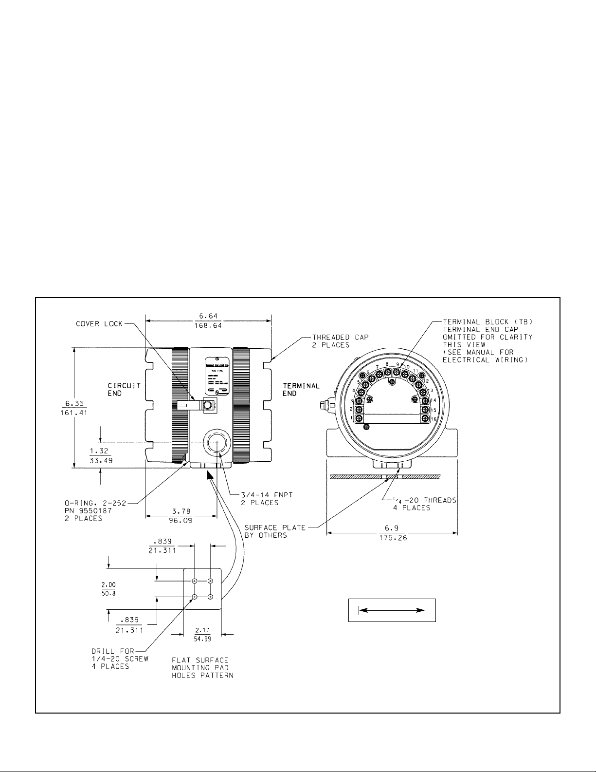
MODEL 5081T-FF/FI INSTALLATION
INSTALLATION
UNPACKING AND INSPECTION
Inspect the shipping container. If it is damaged, contact the
shipper immediately for instructions. Save the box. If there
is no apparent damage, unpack the container. Be sure all
items shown on the packing list are present. If items are
missing, notify Rosemount Analytical immediately.
ROTATING THE DISPLAY
The Model 5081T-FF/F1 display can be rotated 90° left or
right. Disengage the cover lock and remove the front cover.
Remove the three screws holding the PCB stack and gently lift the display board. Do not disengage the ribbon cable
between the display board and the CPU board. Rotate the
display. The black infrared sensor will be at the top of the
display.
INSTALLATION
See Figure 4.
1. Although the analyzer is suitable for outdoor use, do not
install it in direct sunlight or in areas of extreme temperatures.
2. Install the analyzer in an area where vibrations and electromagnetic and radio frequency interference are minimized or absent.
3. Keep the analyzer and sensor wiring at least one foot
from high voltage conductors. Be sure there is easy
access to the analyzer.
4. The conduit connections on the sides of the 5081 housing should be sealed to prevent moisture from entering
the enclosure.
5. The transmitter must not be mounted with both conduit
openings at the top
.
FIGURE 4. Mounting Model 5081T-FF/FI
INCH
MILLIMETER
Page 9

91011
Page 10

Page 11

Page 12

1122131144
Page 13

Page 14

9241515-01
B
CHK
DATE
BY
REVISIONS
DESCRIPTION
A
QTY
Uniloc Division
2400 Barranca Pkwy
Irvine, CA 92606
Rosemount Analytical,
REV
REV
REV
REV
REV
REV
REV
12
SHEET OF
FM A
CERTIFIED BY
THIS DOCUMENT IS
W/O AGENCY APPROVAL
REVISIONS NOT PERMITTED
9241515-01
5081-T-FI
DESCRIPTION
LABEL, I.S. FM
DWG NO
2:1
ECO
LTR
A
REV
5-6-04 893 3
RELEASE DATE ECO NO
Ø .125
±.01 5
.120
B
SIZE
SCALE
5/6/04
5/6/04J. FLOCK
J. FLOCK
SOLID EDGE
THIS DWG CREATED IN
PROJECT
ENGR APVD
CHECKED
PART NO
ITEM
Uniloc
TITLE
BILL OF MATERIAL
DATE
5/3/04
B. JOHNSON
APPROVALS
DRAWN
±.02
1/2
-
+
ANGLES
TOLERANCES
DIMENSIONS ARE IN INCHES
.030
.010
REMOVE BURRS & SHARP EDGES .020 MAX
-
+
-
+
UNLESS OTHERWISE SPECIFIED
.XX
.XXX
1
4
NOMINAL SURFACE FINISH 125
MACHINED FILLET RADII .020 MAX
MATERIAL
FINISH
FM
2.56
4 FINISH:SILKSCREEN BLACK EPOXY PAINT (BAKED).
±.00 5
2.180
±.015
APPROVED
.650
±.02
R
Tamb= 70°C
1.30
.125
CLASS II, DIV. 1, GRPS. E,F & G
PER DWG. 1400298
CLASS III, DIV. 1
CLASS I, DIV.1, GRPS. B,C & D
ROSEMOUNT ANALYTICAL
GRPS. A,B,C,D,E,F & G
CLASS I, II & III, DIV. 1,
INTRINSICALLY SAFE FOR
MODEL
5081-T-FI-67
T4
CONNECTED PER DWG. 1400284
HAZARDOUS AREA WHEN
GRPS. E, F & G
CLASS II AND III, DI V. 1,
DUST IGNITION PROOF
NON-INCENDIVE
CLASS I, DIV. 2, GRPS. A,B,C & D
EXPLOSION PROOF
NEMA 4X ENCLOSURE.
OR SUITABILITY FOR DIV.2.
MAY IMPAIR INTRINSIC SAFETY
WARNING: COMPONENT SUBSTITUTION
9241515-01/A
R .25
4X
±.005
2X FULL R
This document contains information proprietary to
to those who may compete with Rosemount Analytical.
Rosemount Analytical, and is not to be made available
.140
3. ARTWORK IS SHEET 2 OF 2.
2. NO CHANGE WITHOUT FM APPROVAL.
HARDNESS BRINELL 190.
BE ANNEALED & PASSIVATED. MAXIMUM
STEEL .015+/-.005 THICK. MATERIAL TO
1 MATERIAL: AISI 300 SERIES STAINLESS
NOTES: UNLESS OTHERWISE SPECIFIED
Page 15

1155
D
1
REVISION
2
1400298
CHK
DATE
BY
DESCRIPTION
C
B
REV
REV
REV
REV
REV
REV
CERTIFIED BY
THIS DOCUMENT IS
FM A
W/O AGENCY APPROVAL
REVISIONS NOT PERMITTED
A
06-01
A
QTY
Rosemount Analytical Division
Emerson Process Management,
2400 Barranca Pkwy
Irvine, CA 92606
DESCRIPTION
BILL OF MATERIAL
Emerson
DATE
REV
1
1
SHEET OF
1
TYPE
1400298
EXP PROOF 5081-T-FI
DWG NO.
SCHEM, SYSTEM FMRC
TITLE
5/6/04
5/3/04
NONE
D
SIZE
SCALE
5/6/04
2
PART NO.
ECO
LTR
POWER SUPPLY
17.5 VDC MAX
3
4
3
1
C
N
2
1
C
N
1
V
1
R
D
C
°
OM
0
C
1
0
V
7
R
D
OR
F
D
D
V
L
9
E
R
H
D
T
S
A
R
E
5
B
V
C
8
T
R
S
U
M
G
M
N
O
I
C
R
7
V
I
C
R
W
D
L
V
H
S
C
R
6
N
I
D
T
R
5
E
S
N
E
D
T
R
4
4
1
C
N
WIRING LABEL
S
M
D
1
5
H
T
/
F
F
1
6
(
-
H
)
T
/
F
F
(
+
)
12
11
15
16
14
13
RIGID METAL CONDUIT
AND APPROVED SEALS
3
10
9
8
7
6
5
P
N
9
2
4
1
5
2
0
-
0
0
/
A
R
E
S
E
R
V
S
H
E
L
O
D
C
D
1
R
T
D
T
R
2
3
4
3
21
5081-T-FI-67
HAZARDOUS AREA
ITEM
1/2
-
+
ANGLES
TOLERANCES
.030
.010
-
+
-
+
UNLESS OTHERWISE SPECIFIED
.XX
.XXX
CLASS I, DIV 1, GPS B-D
CLASS III, DI V 1
CLASS II, DIV 1, GPS E-G
70°C MAX
J. FLOCK
J. FLOCK
B. JOHNSON
APPROVALS
DRAWN
DIMENSIONS ARE IN INCHES
NOMINAL SURFACE FINISH 125
MACHINED FILLET RADII .020 MAX
REMOVE BURRS & SHARP EDGES .020 MAX
SOLID EDGE
THIS DWG CREATED IN
ENGR APVD
PROJECT
CHECKED
3
FINISH
MATERIAL
A
REVECO NO.
4
RELEASE DATE
5-6-04 8933
5
6
7
6
7
SAFE AREA SAFE AREA
AND APPROVED SEALS
RIGID METAL CONDUIT
3
222
242
225
RECOMMENDED SENSORS:
228
8
Rosemount Analytical, and is not to be made available
This document contains information proprietary to
to those who may compete with Rosemount Analytical.
226
D
C
SENSOR
TOROIDAL
8
3 USE ONLY APPROVED CONDUIT SEALS AND FITT INGS.
2. SEAL REQUIRED AT EACH CONDUIT ENTRANCE.
1. INSTALLATION MUST CONFORM TO THE NEC.
NOTES: UNLESS OTHERWISE SPE CIFIED
B
A
Page 16

1166
D
1
2
3
1400284
CHK
DATE
BY
REVISION
DESCRIPTION
ECO
LTR
C
THIS DOCUMENT IS
APPARATUS
ASSOCIATED
ANY FM APPROVED
B
REV
REV
REV
REV
CERTIFIED BY
FM B
REV
REV
W/O AGENCY APPROVA L
REVISIONS NOT PERMITTED
10
10
Li (uH)
5
5
Ci (nF)
2.52
5.32
Pmax (W)
NON-HAZARDOUS LOCATIONS
TERMINATOR
ANY FM APPROVED
SUBSTITUTION OF COMPONENTS MAY IMPAIR INTRINSIC SAFETY OR
SUITABILITY FOR DIVISION 2.
DISCONNECT POWER BEFORE SERVICING.
TO PREVENT IGNITION OF FLAMMABLE OR COMBUSTIBLE ATMOSPHERES,
360
380
Imax (mA)
TABLE I
17.5
WARNING-
WARNING-
17.5
Vmax (Vdc)
5081-T-FI FISCO PARAMETERS
TERMINATOR
ANY FM APPROVED
SUPPLY / SIGNAL TERMINALS TB 1-15, 16
IIB/
IIC/
C,D,E,F,G
GROUPS
A,B,C,D,E,F,G
A
10-96
B
QTY
Uniloc Division
Rosemount Analytical,
2400 Barranca Pkwy
Irvine, CA 92606
DESCRIPTION
BILL OF MATERIAL
Uniloc
DATE
PART NO.
APPROVALS
ITEM
1/2
-
+
ANGLES
TOLERANCES
DIMENSIONS ARE IN INCHES
.030
.010
REMOVE BURRS & SHARP EDGES .020 MAX
-
+
-
+
UNLESS OTHERWISE SPECIFIED
.XX
.XXX
REV
1
1
SHEET OF
1
TYPE
1400284
5081-T-FI XMTR
FM APPROVALS
SCHEMATIC, INSTALLATION
DWG NO.
NONE
D
5/6/04
J. FLOCK
CHECKED
SIZE
SCALE
5/6/04
J. FLOCK
ENGR APVD
PROJECT
2
THIS DWG CREATED IN
SOLID EDGE
3
FINISH
B
REV
ECO NO.
8933
TITLE
5/3/04
B. JOHNSON
DRAWN
NOMINAL SURFACE FINISH 125
MACHINED FILLET RADII .020 MAX
MATERIAL
4
SUITABLE CLASS III,
GROUPS F & G;
DIVISION 2,
DIVISION 2,
IS CLASS I, II, III,
GROUPS A, B, C, D, E, F, G;
DIVISION 1,
NI CLASS I,
DIVISION 2
SUITABLE CLASS II,
GROUPS A,B,C,D;
ANY FM APPROVED
APPARATUS
INTRINSICALLY SAFE
5081-T-FI
5081-T-FI
MODEL NO.
4
RELEASE DATE
5-6-04
HAZARDOUS (CLASSIFIED) LOCATIONS
15
16
14
13
12
11
5
FISCO
6
7
10
9
8
7
6
5
4
3
21
XMTR
MODEL
5081-T-FI
FM INTRINSIC SAFETY INSTALLATION
5
6
10
/ISA RP12.06 "INSTALLATION OF INTRINSICALLY SAFE SYSTEMS
7
INFRARED
FOR USE IN
(RMT PN 23572-00)
CLASS I AREA ONLY
REMOTE CONTROL UNIT
°C ABOVE SURROUNDING AMBIE NT.
Ca, Ct OR Co
La, Lt OR Lo; OR Lc/Rc (La/Ra OR Lo/Ro) AND Li/Ri (La/Ra OR Lo/R o)
APPROVED CONDUCTIVITY
SENSORS
222,225,226 & 228
242 (1" & 2" ONLY)
8
Rosemount Analytical, and is not to be made available
This document contains information proprietary to
to those who may compete with Rosemount Ana lytical.
D
C
7. THE CONFIGURATION OF ASSOCIATED APPARATUS MUST BE FACTORY MUTUAL RESEARCH APPROVED
9. USE SUPPLY WIRES SUITABLE FOR 5
8. NO REVISION TO DRAWING WITHOUT PRIOR FACTORY MUTUAL RESEARCH APPROVAL.
10 MAXIMUM SENSOR CABLE LENGTH IS 250 FEET.
B
WHEN INSTALLING THIS EQUIPMENT.
WITH ASSOCIATED APPARATUS WHEN THE FOLLOWING IS TRUE:
5. ASSOCIATED APPARATUS MANUFACTURER'S INSTALLATION DRAWING MUST BE FOLLOWED
MORE THAN 250 Vrms OR Vdc.
UNDER THE ASSOCIATED CONCEPT.
6. CONTROL EQUIPMENT CONNECTED TO ASSOCIATED APPARATUS MUST NOT USE OR GENERATE
Vmax OR Ui Voc, Vt OR Uo;
3Ci+ 3Ccable;
Pmax OR Pi Po;
3Li + 3Lcable.
Imax OR Ii Isc, It OR Io;
FIELD DEVICE INPUT ASSOCIATED APPARATUS OUTPUT
4. THE ENTITY CONCEPT ALLOWS INTERCONNECTION OF INTRINSICALLY SAFE APPARATUS
1. INSTALLATION SHOULD BE IN ACCORDANCE WITH ANSI
2. DUST-TIGHT CONDUIT SEAL MUST BE USED WHEN INSTALLED IN CLASS II AND CLASS III ENVIRONMENTS.
3. RESISTANCE BETWEEN INTRINSICALL Y SAFE GROUND AND EARTH GRO UND MUST BE LESS THAN 1.0 Ohm.
A
8
NOTES: UNLESS OTHERWISE SPECIFIED
CODE (ANSI/NFPA 70) SECTIONS 504 AND 505.
FOR HAZARDOUS (CLASSIFIED) LOCATIONS" (EXCEPT CHAPTER 5 FOR FISCO INSTALLATIONS) AND THE NATIONAL ELECTRICAL
Page 17

1177
9241516-01
B
CHK
DATE
BY
A
REV
A
REV
REV
REV
REV
REV
REV
QTY
Uniloc Division
2400 Barranca Pkwy
Rosemount Analytical,
Irvine, CA 92606
2
1
SHEET OF
CERTIFIED BY
CSA
THIS DOCUMENT IS
W/O AGENCY APPROVAL
REVISIONS NOT PERMITTED
REVISIONS
REV
ECO NORELEASE DATE
DESCRIPTION
ECO
LTR
A
8925
5-6-04
±.015.120
±.02
2.56
±.005
2.180
LABEL, I.S. CSA
9241516-01
5081-T-FI
DESCRIPTION
2:1
DWG NO
Uniloc
TITLE
B
SIZE
SCALE
BILL OF MATERIAL
DATE
PART NO
5/3/04
B. JOHNSON
5/6/04
J. FLOCK
5/6/04
J. FLOCK
APPROVALS
SOLID EDGE
ITEM
4 FINISH:SILKSCREEN BLACK EPOXY PAINT (BAKED).
TOLERANCES
UNLESS OTHERWISE SP ECIFIED
.030
+
.XX
+
1/2
-
ANGLES
.010
-
+
.XXX
DRAWN
DIMENSIONS ARE IN INCHES
NOMINAL SURFACE FINISH 125
MACHINED FILLET RADII .020 MA X
REMOVE BURRS & SHARP EDGES .020 MAX
-
THIS DWG CREATED IN
PROJECT
CHECKED
ENGR APVD
1
4
MATERIAL
FINISH
This document contains information proprietary to
Rosemount Analytical, and is not to be made available
Ø .125
to those who may compete with Rosemount Analytical.
R .25
4X
LR34186
ENCLOSURE 4
R
SA
R
Tamb= 70°C
ROSEMOUNT ANALYTICAL
INTRINSICALLY SAFE FOR
Exia ENTITY
5081-T-FI-69
MODEL
CLASS I, GRPS A, B, C & D
CLASS II, GRPS E, F & G
T3A Tamb = 70°C
CLASS III
WARNING: COMPONENT SUBSTITUTION
HAZARDOUS AREA WHEN CONNECTED
MAY IMPAIR INTRINSIC SAFETY.
PER DWG. 1400285
CLASS II, DIV. 2, GRPS E, F & G
SUITABLE FOR
CLASS I, DIV. 2, GRPS A,B,C & D
TION OF COMPONENTS MAY IMPAIR
WARNING-EXPLOSION HAZARD-SUBSTITU-
HAZARDOUS.
DISCONNECT WHILE CIRCUIT IS LIVE
SUITABILITY FOR CLASS I, DIV 2.
UNLESS AREA IS KNOWN TO BE NON-
WARNING-EXPLOSION HAZA RD-DO NOT
T3A
CLASS I, GRPS B,C & D
CLASS III
CLASS II, GRPS E, F & G
WITHIN 50 mm OF THE ENCLOSURE.
ARE LIVE.
SEAL REQUIRED TO BE INSTALLED
KEEP COVER TIGHT WHILE CIRCUITS
Tamb ABOVE 60°C USE 75°C MINIMUM
RATED WIRING
Tamb = 65°C MAX
9241516-01/A
±.01 5.650
±.021.30
.125
.140
2X FULL R
STEEL .015+/-.005 THICK. MATERIAL TO
BE ANNEALED & PASSIVATED. MAXIMUM
HARDNESS BRINELL 190.
3. ARTWORK IS SHEET 2 OF 2.
2. NO CHANGE WITHOUT CSA APPROVAL.
1 MATERIAL: AISI 300 SERIES STAINLESS
NOTES: UNLESS OTHERWISE SPECIFIED
Page 18

1188
D
1
REVISION
2
3
4
1400285
CHK
DATE
YBNOITPIR
C
SED
ECO
LTR
HAZARDOUS AREA
CLASS II, GRPS E-G
IS CLASS I, GRPS A-D
B
A
REV
REV
REV
REV
REV
REV
CERTIFIED BY
CSA
W/O AGENCY APPROVAL
REVISIONS NOT PERMITTED
023
Li (mH)Vmax (Vdc)
27.8
Ci (nF)
.5
Pmax (W)
TABLE I
380
Imax (mA)
5081-T-FI ENTITY PARAMETERS
SUPPLY / SIGNAL TERMINALS TB 1-15, 16
UNCLASSIFIED AREA
UNSPECIFIED
POWER SUPPLY
CSA APPROVED
SUITABLE FOR FISCO
ASSOICATED APPARATUS
C
THIS DOCUMENT IS
17.5 VDC MAX
SEE NOTE 5 AND TABLE 1
DISCONNECT POWER BEFORE SERVICING.
SUITABILITY FOR DIVISION 2.
SUBSTITUTION OF COMPONENTS MAY IMPAIR INTRINSIC SAFETY OR
TO PREVENT IGNITION OF FLAMMABLE OR COMBUSTIBL E ATMOSPHERES,
17.5
WARNING-
WARNING-
5081-T-FI
MODEL NO.
GRPS A-D
CLASS II, DIV 2
GRPS E-G
CLASS III
NI CLASS I, DIV 2
UNLESS OTHERWISE SPECIFIED
QTY
DESCRIPTION
PART NO.
ITEM
BILL OF MATERIAL
TOLERANCES
A
10-96
A
REV
1
1
SHEET OF
Irvine, CA 92606
2400 Barranca Pkwy
Rosemount Analytical,
Uniloc Division
5081-T-FI XMTR CSA
SCHEMATIC, INSTALLATION
Uniloc
TITLE
DATE
5/3/04
5/6/04
5/6/04
B. JOHNSON
J. FLOCK
J. FLOCK
APPROVALS
1/2
-
+
ANGLES
.030
.010
+
-
-
+
.XX
.XXX
DIMENSIONS ARE IN INCHES
MACHINED FILLET RADII .020 MA X
REMOVE BURRS & SHARP EDGES .020 MAX
DRAWN
NOMINAL SURFACE FINISH 125
PROJECT
CHECKED
MATERIAL
ENGR APVD
1
TYPE
1400285
DWG NO.
NONE
D
SIZE
SCALE
2
SOLID EDGE
THIS DWG CREATED IN
3
FINISH
A
ECO NO. REV
8925
4
RELEASE DATE
5-6-04
15
16
14
13
12
11
MODEL
5081-T-FI
10
9
8
7
6
5
4
3
12
5
XMTR
6
5
6
11
7
INFRARED
SENSORS
222,225,226 & 228
FISCO
242 (1" & 2" ONLY)
APPROVED CONDUCTIVITY
FOR USE IN
(RMT PN 23572-00)
CLASS I AREA ONLY
REMOTE CONTROL UNIT
La, Lt OR Lo
Ca, Ct OR Co
8
7
8
CSA INTRINSIC SAFETY INSTALLATION
WHEN INSTALLING THIS EQUI PMENT.
Vmax OR Ui Voc, Vt OR Uo;
Ci+ Ccable;
Imax OR Ii Isc, It OR Io;
Pmax OR Pi Po;
Li+ Lcable.
FIELD DEVICE INPUT ASSOCIATED AP PARATUS OUTPUT
to those who may compete with Rosemount Analytical.
This document contains information proprietary to
Rosemount Analytical, and is not to be made available
D
C
11 MAXIMUM SENSOR CABLE LENGTH IS 250 FEET.
MORE THAN 250 Vrms OR Vdc.
8. THE ASSOCIATED APPARATUS MUST BE CSA APPROVED.
7. CONTROL EQUIPMENT CONNECTED TO ASSOCIATED APPARATUS MUST NOT USE OR GENERATE
9. NO REVISION TO DRAWING W ITHOUT PRIOR CSA APPROVAL.
10. USE SUPPLY WIRES SUITABLE FOR 5 °C ABOVE SURROUNDING AMBIENT.
WITH ASSOCIATED APPARAT US WHEN THE FOLLOWING IS TRUE:
6. ASSOCIATED APPARATUS MANUFACTURER'S INSTALLATION DRAW ING MUST BE FOLLOWED
5. THE ENTITY CONCEPT ALLOWS INTERCONNECTION OF INTRINSICALLY SAFE APPARATUS
4. RESISTANCE BETW EEN INTRINSICALLY SAFE GROUND AND EARTH GROUND MUST BE LESS THAN 1.0 Ohm.
3. DUST-TIGHT CONDUIT SEAL MUST BE USED W HEN INSTALLED IN CLASS II AND CLASS III ENVIRONMENTS.
B
INTRINSICALLY SAFE SYSTEMS FOR HAZARDOUS (CLASSIFIED) LOCATIONS" AND THE CANADIAN
2. INSTALLATION SHOULD BE IN ACCORDANCE WITH ANSI/ISA RP12.06.01 "INSTALL ATION OF
AND ASSOCIATED APPARATUS (SAFETY BARRIER) SHALL MEET THE FOLLOWING REQUIREMENTS:
THE VOLTAGE (Vmax) AND CURRENT (Ima x) OF THE INTRINSICALLY SAFE APPARATUS MUST BE
EQUAL TO OR GREATER THAN THE VOLTAGE (Voc OR Vt) AND CURRENT (Isc OR It) WHICH CAN BE
ELECTRICAL CODE (CSA C22.1).
1. INTRINSICALLY SAFE APPARATUS (MODEL 5081-T-FI, IRC TRANSMITTER)
UNPROTECTED CAPACITANCE (Ci) AND INDUCTANCE (Li) OF THE INTRINSICALLY SAFE APPARATUS,
DELIVERED BY THE ASSOCIATED APPARATUS (SAFETY BARRIER). IN ADDIT ION, THE MAXIMUM
INDUCTANCE (La) WHICH CAN BE SAFELY CONNECTED TO THE AP PARATUS. (REF. TABLE I).
INCLUDING INTERCONNECTING WIRING, MUST BE EQUAL O R LESS THAN THE CAPACITANCE (Ca) AND
NOTES: UNLESS OTHERWISE SPECIFIED
A
Page 19

1199
9241514-01
B
CHK
DATE
BY
THIS DOCUMENT IS
CERTIFIED BY
A
REV
REV
Baseefa
REV
REV
REV
REV
REVISIONS NOT PERMITTED
W/O AGENCY APPROVAL
21
A
QTY
Rosemount Analytical,
Uniloc Division
2400 Barranca Pkw y
Irvine, CA 92606
Related Draw ing
the Authorized Person
without the approval of
Baseefa Certified Product
No modifications permitted
REV
SHEET OF
REVISIONS
REV
ECO NORELEASE DATE
DESCRIPTION
ECO
LTR
A
8925
5-6-04
±.015
.120
±.02
2.56
±.005
2.180
5081-T-FI
5/6/04
J. FLOCK
PROJECT
ENGR APVD
1
9241514-01
DWG NO
B
SIZE
SOLID EDGE
THIS DWG CREATED IN
4
FINISH
2:1
SCALE
DESCRIPTION
LABEL, I.S. BAS/ATEX
Uniloc
TITLE
BILL OF MATERIAL
DATE
5/3/04
5/6/04
PART NO
ITEM
4 FINISH:SILKSCREEN BLACK EPOXY PAINT (BAKED).
TOLERANCES
UNLESS OTHERWISE SP ECIFIED
.030
+
.XX
1/2
+
ANGLES
-
-
.010
+
.XXX
B. JOHNSON
J. FLOCK
APPROVALS
DRAWN
CHECKED
DIMENSIONS ARE IN INCHES
NOMINAL SURFACE FINISH 125
MACHINED FILLET RADII .020 MAX
REMOVE BURRS & SHARP EDGES .020 MAX
-
MATERIAL
This document contains information proprietary to
to those who may compete with Rosemount Analytical.
Rosemount Analytical, and is not to be made available
Ø .125
±.015.650
II 1 G
RR
±.02
1.30
1180
ROSEMOUNT ANALYTICAL
MODEL 5081-T-FI-73
EEx ia IIC T4
Baseefa03ATEX0399
FISCO SUPPLY
Tamb = -20°C TO +65°C
Ui = 17.5 VDC
F
µ
µH
Li= 0
Ci= 0
Pi = 5.32 W
Ii = 380 mA
9241514-01/A
.125
R .25
4X
±.005
2X FULL R
.140
STEEL .015+/-.005 THICK. MATERIAL TO
BE ANNEALED & PASSIVATED. MAXIMUM
3. ARTWORK IS SHEET 2 OF 2.
2. NO CHANGE WITHOUT BASEEFA APPROVAL.
1 MATERIAL: AISI 300 SERIES STAINLESS
HARDNESS BRINELL 190.
NOTES: UNLESS OTHERWISE SPECIFIED
Page 20

2200
D
1
REVISION
2
3
4
1400286
CHK
DATE
YBN
O
IT
P
IRCSED
ECO
LTR
C
UNSPECIFIED
17.5 VDC MAX
POWER SUPPLY
B
0
Li (uH)Vmax (Vdc)
0
Ci (uF)
UNCLASSIFIED AREA
5.32
Pmax (W)
ATEX AP PROVE D
SEE NOTE 3 AND TABLE 1
ASSO CIATED APPARAT US
TO PREVENT I GNITION OF FLAMMABLE OR COMBUSTIBLE ATMOS PHERES,
DISCONNECT POWER BEFORE SERVICING.
SUBSTITUTION OF C OMPONENTS MAY IMP AIR IN TRINSIC SAFETY.
TABLE I
380
Imax (mA)
5081-T-FI ENTITY PARAMETERS
(ZONE 0)
1180
II 1 G
Baseefa03ATEX0399
EEx ia IIC T4
WARNING-
WARNING-
17.5
SUPP LY / SI GNAL TER MINALS TB1 15 AND 16
MODEL NO.
5081-T-FI
HAZARDOUS AREA
A
10-96
REV
SCHEMATIC, INSTALLATION
J. FLOCK
CHECKED
MATERIAL
the Authorized Person
A
1
SHEET OF1
1
TYPE
1400286
ATEX ZONE 0
5081-T-FI XMTR
NONE
DWG NO.
D
SIZE
SCALE
5/6/04
5/6/04
J. FLOCK
PROJECT
ENGR APVD
2
SOLID EDGE
THIS DWG CREATED IN
3
FINISH
A
ECO NO. RE V
8925
5-6-04
4
RELEASE DATE
Related Drawing
QTY
Rosemount Analytical,
2400 Barranca Pkwy
Irvine, CA 92606
Uniloc Division
DESCRIPTION
BILL OF MATERIAL
Uniloc
TITLE
DATE
5/3/04
PART NO.
B. JOHNSON
APPROVALS
ITEM
DRAWN
1/2
-
+
ANGLES
TOLERANCES
DIMENSIONS ARE IN INCHES
NOMINAL SURFACE FINISH 125
MACHINED FILLET RADII .020 MAX
.030
.010
+
-
+
REMOVE BURRS & SHARP EDGES .020 MAX
UNLESS OTHERWISE SPECIFIED
.XX
.XXX
without the approval of
Baseefa Certified Product
No modifications permitted
15
16
14
13
12
11
5
6
FISCO
10
9
8
7
6
5
4
3
12
XMTR
MODEL
5081-T-FI
5
6
9
ATEX INTRINSIC SAFETY INSTALLATION
7
SENSORS
CONDUCTIVITY
222,225,226 & 228.
242 (1" & 2" ONLY)
A
REV
REV
REV
REV
REV
REV
8
CERTIFIED BY
THIS DOCUMENT IS
Baseefa
Rosemount Analytical, and is not to be made available
This document contains information proprietary to
to those who may compete with Rosemount Analytical.
W/O AGENCY APPROVAL
REVISIONS NOT PERMITTED
D
ZONE 0
INFRARED
FOR USE IN
(RMT PN 23572-00)
REMOTE CONTROL UNIT
C
9
La, Lt OR Lo
Po;
Ca, Ct OR Co
Isc, It OR Io;
Voc, Vt OR Uo;
CAN BE DELIVERED BY THE ASSOCIATED APPARATUS (SAFETY BARRIER). IN ADDITION, THE MAXIMUM
MUST BE EQUAL TO OR GREATER THAN THE VOLTAGE (Voc OR Vt) AND CURRENT (Isc OR It) WHICH
FIE LDBUS D EVICE S) AND ASS OCIATED APPARATUS ( SAFETY BARRIE R) SHALL MEET TH E FOLLO WING
REQUIREMENTS: THE VOLTAGE (Vmax) AND CURRENT (Imax) OF THE INTRINSICALLY SAFE APPARATUS
WHEN INSTALLING THIS EQUIPMENT.
9 MAXIMUM SENSOR CABLE LENGTH IS 250 FEET.
8. PROCESS RESISTIVITY MUST BE LESS THAN 10 OHMS.
MORE THAN 250 Vrms OR Vdc.
7. USE SUPPLY WIRES SUITABLE FOR 5^C ABOVE SURROUNDING AMBIENT.
6. ANY ASSOCIATE D APPARATU S MUST BE ATEX APPR OVED.
5. CONTROL EQUIPMENT CONNECTED TO ASSOCIATED APPARATUS MUST NOT USE OR GENERATE
WITH ASSOCIATED APPARATUS WHEN THE FOLLOWING IS TRUE:
Ci+ Ccable;
Vmax OR Ui
Li+ Lcable.
FIELD DEVICE INPUT ASSOCIATED APPARATUS OUTPUT
Pmax OR Pi
4. ASSOCIATED APPARATUS MANUFACTURER'S INSTALLATION DRAWING MUST BE FOLLOWED
Imax OR Ii
3. THE ENTI TY CONCEPT ALLOWS INTERCONNE CTION OF INTRINSI CALLY SAFE APPARATUS
1. INTRINSICALLY SAFE APPARATUS (MODEL 5081-T-FI, FIELDBUS TERMINATOR AND ANY ADDITIONAL
2. RESISTANCE BETWEEN INTRINSICALLY SAFE GROUND AND EARTH GROUND MUST BE LESS THAN 1.0 Ohm.
B
INCLUDING INTERCONNECTING WIRING, MUST BE EQUAL OR LESS THAN THE CAPACITANCE (Ca) AND
UNPROTECTED CAPACITANCE (Ci) AND I NDUCTANCE (Li) OF THE INTRINSI CALLY SAFE APPARATUS,
A
7
8
INDUCTANCE (La) WHI CH CAN BE SAFELY CONNECTED TO THE APPARATUS. (REF . TABLE I).
NOTES: UNLESS OTHERWISE SPECIFI ED
Page 21

2211
OVERVIEW
This section gives general procedures for routine maintenance of the 5081-T transmitter. The transmitter needs almost no
routine maintenance.
TRANSMITTER MAINTENANCE
Periodically clean the transmitter window with household ammonia or glass cleaner. The detector for the infrared remote
controller is located behind the window at the top of the transmitter face. The window in front of the detector must be kept
clean.
Most components of the transmitter are replaceable. Refer to figure below and table on next page for parts and part numbers.
Exploded View of Model 5081-T-FF/FI Transmitter
Three screws (part 13 in the drawing) hold the three circuit boards in place. Removing the screws allows the display
board (part 2) and the CPU board (part 3) to be easily removed. A ribbon cable connects the boards. The cable plugs
into the CPU board and is permanently attached to the display board. A 16 pin and socket connector holds the CPU and
analog (part 4) boards together. Five screws hold the terminal block (part 5) to the center housing (part 7), and the 16
pins on the terminal block mate with 16 sockets on the back side of the analog board. Use caution when separating the
terminal block from the analog board. The pin and socket connection is tight.
MODEL 5081T-FF/FI MAINTENANCE
MAINTENANCE
Page 22

2222
Replacement Parts for Model 5081-T-FF/FI Transmitter
Location in Shipping
drawing PN Description Weight
1 23992-07 PCB stack consisting of the CPU (part 3) and analog (part 4) boards, 1 lb/0.5 kg
display board is not included, CPU and analog boards are factorycalibrated as a unit and cannot be ordered separately
2 23638-01 LCD display PCB 1 lb/0.5 kg
5 33337-02 Terminal block 1 lb/0.5 kg
6 23593-01 Enclosure cover, front with glass window 3 lb/1.5 kg
7 33360-00 Enclosure, center housing 4 lb/1.5 kg
8 33362-00 Enclosure cover, rear 3 lb/1.0 kg
9 6560135 Desiccant in bag, one each 1 lb/0.5 kg
10 9550187 O-ring (2-252), one, front and rear covers each require an O-ring 1 lb/0.5 kg
12 note Screw, 8-32 x 0.5 inch, for attaching terminal block to center housing *
13 note Screw, 8-32 x 1.75 inch, for attaching circuit board stack to center *
housing
14 33342-00 Cover lock 1 lb/0.5 kg
15 33343-00 Locking bracket nut 1 lb/0.5 kg
16 note Screw, 10-24 x 0.38 inch, for attaching cover lock and locking bracket *
nut to center housing
NOTE: For information only. Screws cannot be purchased from Rosemount Analytical.
* Weights are rounded up to the nearest whole pound or 0.5 kg.
MODEL 5081T-FF/FI MAINTENANCE
Page 23

2233
QUICK-START
1. On the Remote, press PROG, NEXT, ENTER.
2. Use the arrow buttons to select COnduc (conductivity),
nAOH (Sodium Hydroxide 0-15%), HCL (Hydrochloric
Acid 0-16%), H2SO4L (Sulfuric Acid 0-30%), H2SO4H
(Sulfuric Acid 95-99.99%), or CuSt (custom curve)
mode. Press ENTER. If you chose CuSt, continue with
step 3. If you chose COnduc or one of the preprogrammed % concentration modes, skip step 3 and go to
step 4.
3. If you selected CuST, you will see the Setup Custom
screen. To move to the custom curve configuration
menu, press ENTER. You will automatically return to
this same Setup Custom screen after configuration is
complete. To continue transmitter display programming,
press NEXT in the Setup Custom screen.
4. Use the arrow keys to toggle temperature units between
Celsius and Farenheit.
5. Press ENTER then RESET.
6. Press PROG, ENTER.
7. Use the arrow key to toggle t AutO to On or OFF to
select using either the process temperature (tAutO =
On) or a manual temperature (tAutO = OFF). Press
ENTER. If you selected t AutO = OFF, you will be
prompted to enter the manual temperature; use the
arrow keys, then press ENTER.
8. If you selected CondUC in step 2, you will see a COMP
(Temperature Compensation type) screen. Use the
arrow keys to select desired temperature compensation: LinEAr (linear) or nOnE (raw or uncompensated
conductivity). Press ENTER. If you are in LinEAR
mode, you can now enter a particular temperature slope
(default is 2%/degC), then press ENTER to apply the
slope.
9. Press RESET.
10. Press CAL, NEXT, NEXT, NEXT, ENTER.
11. Use the arrow buttons to enter the cell constant of the
sensor. Press ENTER, then EXIT.
12. To “zero” the sensor in air, press CAL, NEXT, ENTER.
13. Hold the sensor in air to zero. Press ENTER, then EXIT.
14. If you are measuring % concentration (nAOH, HCL,
H2SO4L, or H2SO4H) or custom curve (CuSt), quick
start is complete; proceed to step 20.
15. If you are measuring conductivity (CondUC), then standardize the sensor by placing the sensor in a solution
of known conductivity value. Press CAL, ENTER.
16. Use the arrow buttons to enter the current conductivity
value of the solution. Press ENTER.
17. Press RESET.
To reset transmiter to factory default settings:
1. Press PROGRAM, NEXT, NEXT, NEXT. The screen
should say "dEFAULt". Press ENTER.
2. Use the arrow keys to toggle between nO (retain your
configuration and calibration settings) and YES (restore
factory default settings to all variables).
3. Press ENTER, then EXIT.
ENGINEERING SPECIFICATIONS
Page 24

Credit Cards for U.S. Purchases Only.
The right people,
the right answers,
right now.
ON-LINE ORDERING NOW AVAILABLE ON OUR WEB SITE
http://www.raihome.com
Specifications subject to change without notice.
Emerson Process Management
Liquid Division
2400 Barranca Parkway
Irvine, CA 92606 USA
Tel: (949) 757-8500
Fax: (949) 474-7250
http://www.raihome.com
© Rosemount Analytical Inc. 2005
 Loading...