

Page 1
Model 5081-T
Two-Wire Toroidal Conductivity Transmitter
Instruction Manual
PN 51-5081T/rev.D
February 2006
Page 2

Emerson Process Management
Rosemount Analytical Inc.
2400 Barranca Parkway
Irvine, CA 92606 USA
Tel: (949) 757-8500
Fax: (949) 474-7250
http://www.raihome.com
© Rosemount Analytical Inc. 2006
ESSENTIAL
INSTRUCTIONS
READ THIS PAGE BEFORE PROCEEDING!
Rosemount Analytical designs, manufactures, and tests its products to meet many national and international
standards. Because these instruments are sophisticated technical products, you must properly install, use, and
maintain them to ensure they continue to operate within their normal specifications. The following instructions
must be adhered to and integrated into your safety program when installing, using, and maintaining Rosemount
Analytical products. Failure to follow the proper instructions may cause any one of the following situations to
occur: Loss of life; personal injury; property damage; damage to this instrument; and warranty invalidation.
• Read all instructions prior to installing, operating, and servicing the product. If this Instruction Manual is not the
correct manual, telephone 1-800-654-7768 and the requested manual will be provided. Save this Instruction
Manual for future reference.
• If you do not understand any of the instructions, contact your Rosemount representative for clarification.
• Follow all warnings, cautions, and instructions marked on and supplied with the product.
• Inform and educate your personnel in the proper installation, operation, and maintenance of the product.
• Install your equipment as specified in the Installation Instructions of the appropriate Instruction Manual and per
applicable local and national codes. Connect all products to the proper electrical and pressure sources.
• To ensure proper performance, use qualified personnel to install, operate, update, program, and maintain the
product.
• When replacement parts are required, ensure that qualified people use replacement parts specified by
Rosemount. Unauthorized parts and procedures can affect the product’s performance and place the safe
operation of your process at risk. Look alike substitutions may result in fire, electrical hazards, or improper
operation.
• Ensure that all equipment doors are closed and protective covers are in place, except when maintenance is
being performed by qualified persons, to prevent electrical shock and personal injury.
CAUTION
If a Model 375 Universal Hart® Communicator is used with these transmitters, the software within the Model 375 may require
modification. If a software modification is required, please contact your local Emerson Process Management Service Group
or National Response Center at 1-800-654-7768.
About This Document
This manual contains instructions for installation and operation of the Model 5081-T Two-Wire
Conductivity Transmitter. The following list provides notes concerning all revisions of this document.
Rev. Level Date Notes
A 1/05 This is the initial release of the product manual. The manual has been
reformatted to reflect the Emerson documentation style and updated to
reflect any changes in the product offering. This manual contains
information on HART Smart and F
OUNDATION Fieldbus versions of
Model 5081-T.
B 5/05 Fix LED font on pages 4, 30, 34, 35, 39.
C 10/05 Add instructions to enable autoranging or fixed measurement renges on
page 50.
D 2/06 Add FISCO agency certifications drawings, pp. 30-36.
Page 3

i
MODEL 5081-T TABLE OF CONTENTS
MODEL 5081-T
TWO-WIRE TRANSMITTER
TABLE OF CONTENTS
Section Title Page
1.0 DESCRIPTION AND SPECIFICATIONS ................................................................ 1
1.1 Features and Applications........................................................................................ 1
1.2 Specifications........................................................................................................... 2
1.3 Hazardous Location Approval.................................................................................. 3
1.4 Transmitter Display During Calibration and Programming....................................... 4
1.5 Infrared Remote Controller ...................................................................................... 4
1.6 HART Communications ........................................................................................... 5
1.7 FOUNDATION Fieldbus............................................................................................... 6
1.8 Asset Management Solutions ................................................................................. 6
2.0 INSTALLATION ....................................................................................................... 8
2.1 Unpacking and Inspection........................................................................................ 8
2.2 Orienting the Display Board ..................................................................................... 8
2.3 Mechanical Installation............................................................................................. 8
2.4 Power Supply/Current Loop Wiring for Model 5081-T-HT ....................................... 12
2.5 Power Supply Wiring for Model 5081-T-FF/FI.......................................................... 13
3.0 WIRING.................................................................................................................... 14
3.1 Sensor Wiring .......................................................................................................... 14
3.2 Electrical Installation ................................................................................................ 16
4.0 INTRINSICALLY SAFE AND EXPLOSION PROOF INSTALLATIONS.................. 19
4.1 Intrinsically Safe and Explosion-Proof Installation for Model 5081-T-HT ................. 19
4.2 Intrinsically Safe and Explosion-Proof Installation for Model 5081-T-FF ................. 25
4.3 Intrinsically Safe and Explosion-Proof Installation for Model 5081-T-FI .................. 30
5.0 DISPLAY AND OPERATION ................................................................................... 37
5.1 Displays ................................................................................................................... 37
5.2 Infrared Remote Controller (IRC) — Key Functions ................................................ 38
5.3 Quick Start for Model 5081-T-HT ............................................................................. 39
5.4 Quick Start for Model 5081-T-FF/FI ......................................................................... 40
5.5 Menu Tree................................................................................................................ 41
5.6 Diagnostic Messages............................................................................................... 43
5.7 Default Setting ......................................................................................................... 43
5.8 Security .................................................................................................................... 45
5.9 Using Hold ............................................................................................................... 45
6.0 START-UP AND CALIBRATION ............................................................................. 46
6.1 Accessing the Calibrate Menu ................................................................................. 46
6.2 Calibrate Menu......................................................................................................... 47
....................................................................................Continued on following page
Page 4

MODEL 5081-T TABLE OF CONTENTS
TABLE OF CONTENTS CONT’D
ii
7.0 PROGRAMMING..................................................................................................... 50
7.1 General .................................................................................................................... 50
7.2 Output ...................................................................................................................... 51
7.3 Temp ........................................................................................................................ 53
7.4 Display ..................................................................................................................... 54
7.5 HART ....................................................................................................................... 55
7.6 Setup Cust ............................................................................................................... 56
7.7 Range ...................................................................................................................... 57
7.8 Default......................................................................................................................57
8.0 FOUNDATION FIELDBUS OPERATION................................................................ 58
9.0 OPERATION WITH MODEL 375............................................................................. 59
9.1 Note on Model 375 or 275 Communicator ............................................................... 59
9.2 Connecting the Communicator ................................................................................ 59
9.3 Operation ................................................................................................................. 60
10.0 DIAGNOSIS AND TROUBLESHOOTING............................................................... 75
10.1 Overview .................................................................................................................. 75
10.2 Fault Conditions ....................................................................................................... 77
10.3 Diagnostic Messages............................................................................................... 78
10.4 Quick Troubleshooting Guide................................................................................... 79
10.5 Systematic Troubleshooting..................................................................................... 80
10.6 RTD Resistance Values ........................................................................................... 81
10.7 Warning and Fault Messages .................................................................................. 82
10.8 Troubleshooting When a Fault or Warning Message is Showing ............................ 83
11.0 MAINTENANCE ...................................................................................................... 86
11.1 Overview .................................................................................................................. 86
11.2 Preventative Maintenance ....................................................................................... 86
11.3 Corrective Maintenance ........................................................................................... 86
12.0 THEORY OF OPERATION ..................................................................................... 89
12.1 Overview .................................................................................................................. 89
12.2 Conductivity ............................................................................................................. 89
12.3 HART Communication ............................................................................................. 89
12.4 Output Logic............................................................................................................. 89
13.0 RETURN OF MATERIAL......................................................................................... 91
Page 5

iii
MODEL 5081-T TABLE OF CONTENTS
LIST OF FIGURES
Number Title Page
1-1 Transmitter Display During Calibration and Programming ....................................... 4
1-2 Infrared Remote Controller....................................................................................... 4
1-3 HART Communicator ............................................................................................... 5
1-4 Configuring Model 5081-T Transmitter with Foundation Fieldbus ............................ 6
1-5 AMS Main Menu Tools ............................................................................................. 7
2-1 Mounting the Model 5081-T Transmitter on a Flat Surface ...................................... 9
2-2 Using the Pipe Mounting Kit to Attach the Model 5081-T to a pipe .......................... 10
2-3 Load/Power Supply Wiring Requirements................................................................ 12
2-4 Model 5081-T-HT Power Wiring Details ................................................................... 12
2-5 Typical Fieldbus Network Electrical Wiring Configuration ........................................ 13
2-6 Model 5081-T-FF Power Wiring Details ................................................................... 13
3-1 Wiring Model 5081-T-HT .......................................................................................... 14
3-2 Power Supply/Current Loop Wiring for Model 5081-T-HT........................................ 15
3-3 Power Supply/Current Loop Wiring for Model 5081-T-FF ........................................ 15
3-4 Power Supply and Sensor Wiring for Model 5081-T ................................................ 15
3-5 Wiring Model 242 Sensor to Model 5081-T Transmitter .......................................... 16
3-6 Wiring Models 222, 225, 226, 228, 242, 247 to Model 5081-T Transmitter................. 17
3-7 Wiring Models 222, 225, 226, 228 to Model 5081-T Transmitter................................ 18
4-1 Model 5081-T-HT Infrared Remote Control — CSA, FM, & ATEX approvals........... 19
4-2 Model 5081-T-FF Infrared Remote Control — CSA, FM, & ATEX approvals ........... 19
4-3 FM Explosion-Proof Installation for Model 5081-T-HT ............................................. 20
4-4 FM Intrinsically Safe Installation for Model 5081-T-HT............................................. 21
4-5 CSA Intrinsically Safe Installation for Model 5081-T-HT........................................... 22
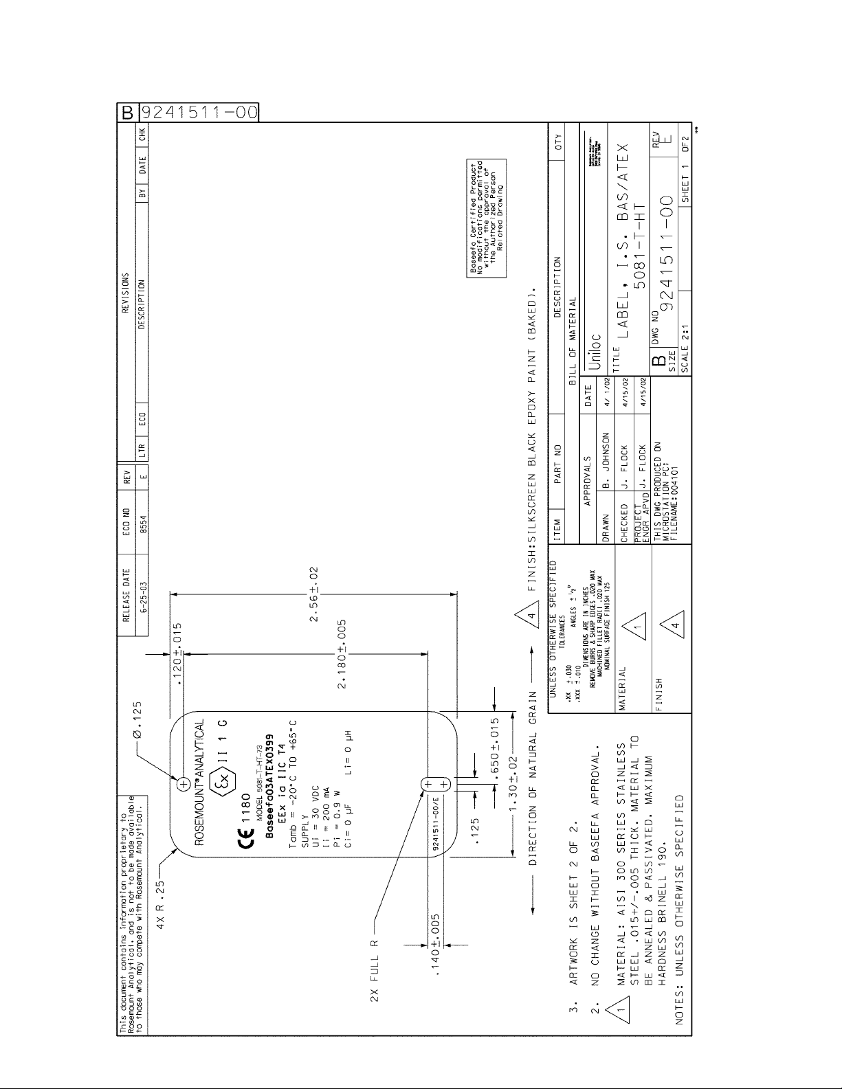
4-6 ATEX Intrinsically Safe Label for Model 5081-T-HT ................................................. 23
4-7 ATEX Intrinsically Safe Installation for Model 5081-T-HT......................................... 24
4-8 FM Explosion-Proof Installation for Model 5081-T-FF .............................................. 25
4-9 FM Intrinsically Safe Installation for Model 5081-T-FF ............................................. 26
4-10 CSA Intrinsically Safe Installation for Model 5081-T-FF ........................................... 27
4-11 ATEX Intrinsically Safe Label for Model 5081-T-FF ................................................. 28
4-12 ATEX Intrinsically Safe Installation for Model 5081-T-FF ......................................... 29
4-13 FM Explosion-Proof Installation for Model 5081-T-FI ............................................... 30
4-14 FM Intrinsically Safe Label for Model 5081-T-FI....................................................... 31
4-15 FM Intrinsically Safe Installation for Model 5081-T-FI .............................................. 32
4-16 CSA Intrinsically Safe Label for Model 5081-T-FI..................................................... 33
4-17 CSA Intrinsically Safe Installation for Model 5081-T-FI ............................................ 34
4-18 ATEX Intrinsically Safe Label for Model 5081-T-FI................................................... 35
4-19 ATEX Intrinsically Safe Installation for Model 5081-T-FI .......................................... 36
Page 6

iv
MODEL 5081-T TABLE OF CONTENTS
LIST OF FIGURES - CONT’D
Number Title Page
5-1 Process Display Screen ........................................................................................... 37
5-2 Program Display Screen .......................................................................................... 37
5-3 Infrared Remote Controller....................................................................................... 38
5-4 Menu Tree for Model 5081-T-HT .............................................................................. 41
5-5 Menu Tree for Model 5081-T-FF ............................................................................. 42
6-1 Menu Tree ............................................................................................................... 46
6-2 Current Output Calibration ....................................................................................... 47
8-1 Functional Block Diagram for the Model 5081-T with F
OUNDATION Fieldbus.......... 58
9-1 Connecting the HART Communicator ...................................................................... 59
9-2 5081-T-HT HART/Model 375 Menu Tree.................................................................. 61
9-3 5081-T-FF/FI Model 375 Menu Tree ........................................................................ 65
10-1 Diagnose Menu Segments ....................................................................................... 75
10-2 Disabling Fault Annunciation.................................................................................... 77
10-3 Warning Annunciation............................................................................................... 77
10-4 Troubleshooting Flow Chart ..................................................................................... 80
10-5 Conductivity Determination ...................................................................................... 81
11-1 Hold Annunciation .................................................................................................... 86
LIST OF TABLES
Number Title Page
5-1 Default Settings fro Model 5081-T-FF ...................................................................... 43
5-2 Default Settings fro Model 5081-T-HT...................................................................... 44
6-1 Calibrate Menu Mnemonics...................................................................................... 49
10-1 Diagnostic Variables Mnemonics ............................................................................. 76
10-2 Diagnostic Fault Messages ...................................................................................... 78
10-3 Quick Troubleshooting Guide ................................................................................... 79
10-4 RTD Resistance Values............................................................................................ 81
11-1 Model 5081-T Replacement Parts and Accessories................................................. 87
Page 7

1
MODEL 5081-T SECTION 1.0
DESCRIPTION AND SPECIFICATIONS
SECTION 1.0
DESCRIPTION AND SPECIFICATIONS
• CHOICE OF COMMUNICATION PROTOCOL: HART or FOUNDATION Fieldbus.
• LARGE, EASY-TO-READ two-line display shows the process measurement and temperature.
• SIMPLE MENU STRUCTURE.
• ROBUST NEMA 4X and NEMA 7B ENCLOSURE.
• INTRINSICALLY SAFE DESIGN allows the transmitter to be used in hazardous environments
(with appropriate safety barriers).
• NON-VOLATILE MEMORY retains program settings and calibration data during power failures.
• MEASURES CONDUCTIVITY, % CONCENTRATION, PPM, OR CUSTOM CURVE VARIABLE.
• AUTOMATIC TC RECOGNITION simplifies start up.
• AUTOMATIC/MANUAL TEMPERATURE COMPENSATION ensures accurate monitoring and control.
• AUTOMATIC COMPENSATION FOR SENSOR CABLE RESISTANCE improves accuracy of high
conductivity/ low resistivity measurements.
• BUILT-IN PERCENT CONCENTRATION CURVES INCLUDE 0-15% NaOH, 0-16% HCl, 0-30%
and 96-99.7% H
2SO4
.
1.1 FEATURES AND APPLICATIONS
The Model 5081-T can be used to measure conductivity
in a variety of process liquids. The 5081 is compatible
with most Rosemount Analytical sensors. See the
Specifications section for details.
The transmitter has a rugged, weatherproof, corrosionresistant enclosure (NEMA 4X and IP65) of epoxy-painted
aluminum. The enclosure also meets NEMA 7B explosion-proof standards.
The transmitter has a two-line seven-segment display.
The main measurement appears in 0.8-inch (20 mm) high
numerals. The secondary measurement, temperature
(and pH if free chlorine is being measured), appears in
0.3-inch (7 mm) high digits.
Two digital communication protocols are available: HART
(model option -HT) and FOUNDATION Fieldbus (model
options -FF and FI). Digital communications allows
access to AMS (Asset Management Solutions). Use AMS
to set up and configure the transmitter, read process variables, and troubleshoot problems from a personal computer or host anywhere in the plant.
A handheld infrared remote controller or the HART and
F
OUNDATION Fieldbus Model 375 communicator can also
be used for programming and calibrating the transmitter.
The remote controller works from as far away as six feet.
Housed in a rugged NEMA 4X and NEMA 7 case, the
5081T measures conductivity or resistivity in the harshest
environments. Transmitter can also be configured, using
the "Custom Curve" feature, to measure ppm, %, or a no
unit variable according to a programmable conductivity vs.
variable curve. The transmitter will automatically recognize the type of RTD (Pt100 or Pt1000) being used.
Measurements are automatically corrected for the resistance of the sensor cable to improve accuracy of high conductivity readings. Temperature compensation choices
are linear slope correction or none (display of raw conductivity.
Page 8
2
MODEL 5081-T SECTION 1.0
DESCRIPTION AND SPECIFICATIONS
1.2 SPECIFICATIONS
1.2.1 GENERAL SPECIFICATIONS
Enclosure: Cast aluminum containing less than 6% mag-
nesium, with epoxy polyester coating. NEMA 4X
(IP65) and NEMA 7B. Neoprene O-ring cover seals.
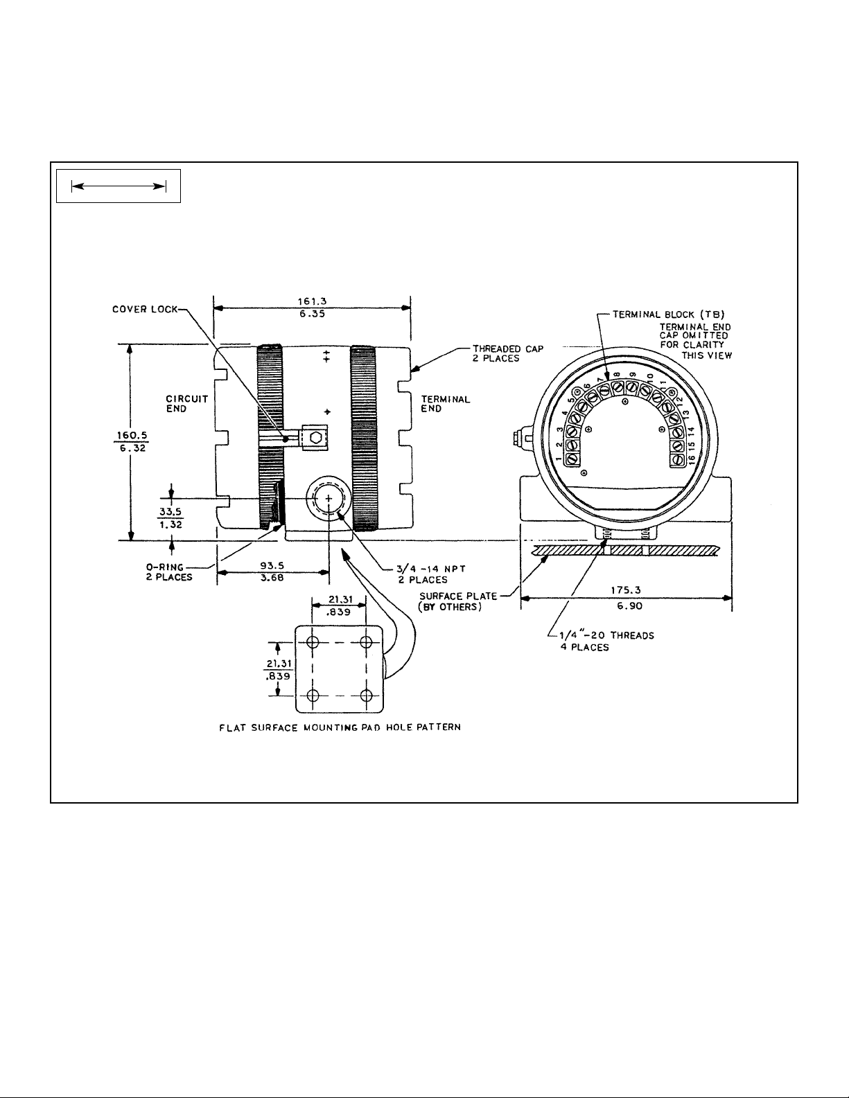
Dimensions: See drawing.
Conduit Openings: ¾-in. FNPT
Ambient Temperature: -4 to 149°F (-20 to 65°C)
Storage Temperature: -22 to 176°F (-30 to 80°C)
Relative Humidity: 0 to 95% (non-condensing)
Weight/Shipping Weight: 10 lb/10 lb (4.5/5.0 kg)
Display: Two-line LCD; first line shows process variable
(pH, ORP, conductivity, % concentration, oxygen,
ozone, or chlorine), second line shows process temperature and output current. For pH/chlorine combination, the second line can be toggled to show pH. Fault
and warning messages, when triggered, alternate with
temperature and output readings.
First line: 7 segment LCD, 0.8 in. (20 mm) high.
Second line: 7 segment LCD, 0.3 in. (7mm) high.
Display board can be rotated 90 degrees clockwise or
counterclockwise.
During calibration and programming, messages and
prompts appear in the second line.
Temperature resolution: 0.1°C
Hazardous Location Approval: For details, see specifi-
cations for the measurement of interest.
RFI/EMI: EN-61326
Digital Communications:
HART —
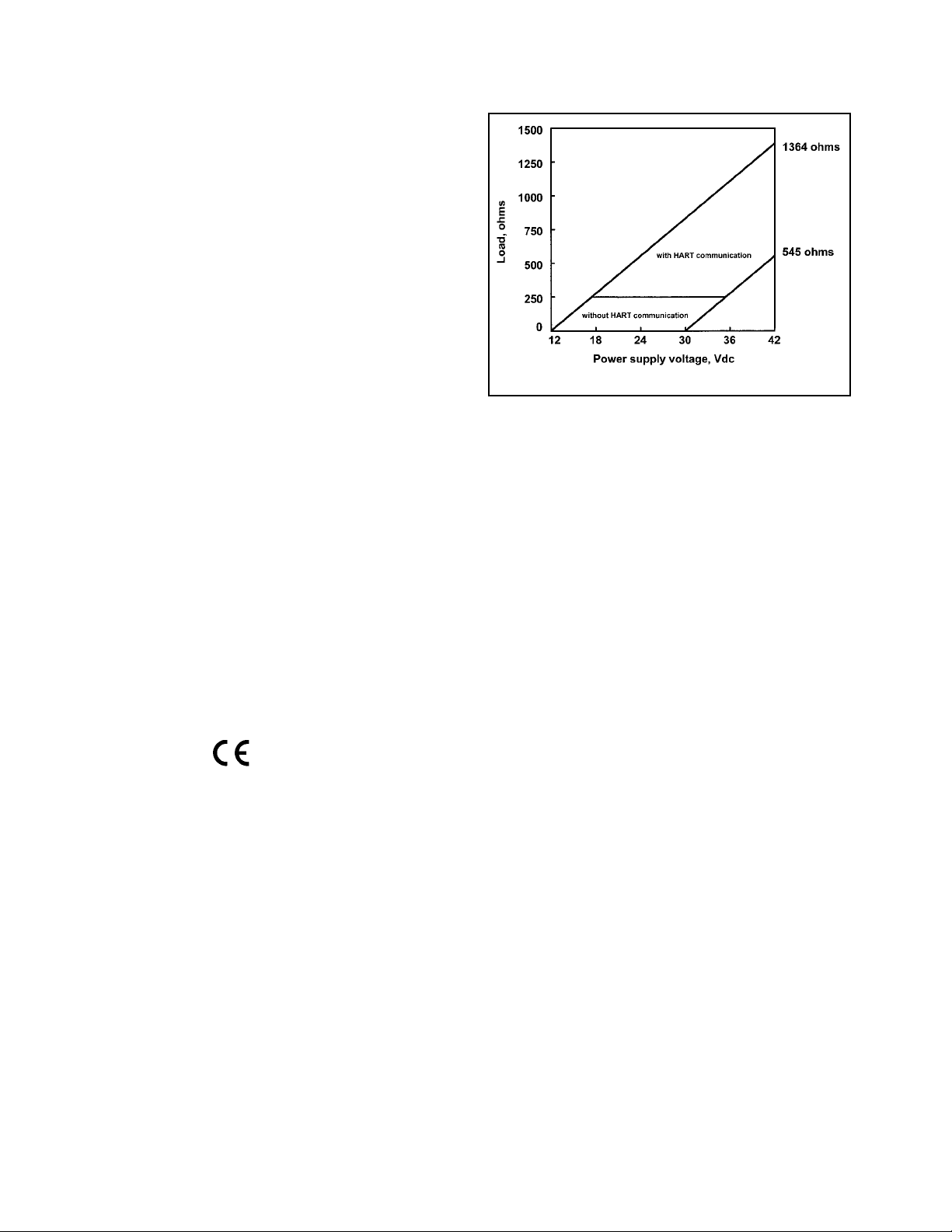
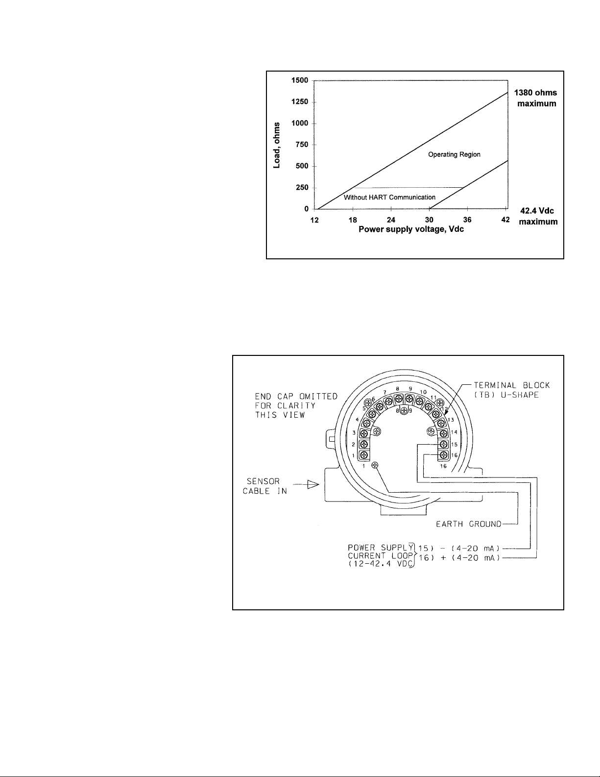
Power & Load Requirements:
Supply voltage at the transmitter terminals should be at
least 12 Vdc. Power supply voltage should cover the voltage drop on the cable plus the external load resistor
required for HART communications (250 Ω minimum).
Minimum power supply voltage is 12 Vdc. Maximum power
supply voltage is 42.4 Vdc (30 Vdc for intrinsically safe
operation). The graph shows the supply voltage required
to maintain 12 Vdc (upper line) and 30 Vdc (lower line) at
the transmitter terminals when the current is 22 mA.
Analog Output: Two-wire, 4-20 mA output with superim-
posed HART digital signal. Fully scalable over the
operating range of the sensor.
Output accuracy: ±0.05 mA
FOUNDATION FIELDBUS —
Power & Load Requirements: A power supply voltage of
9-32 Vdc at 22 mA is required.
1.2.2 FUNCTIONAL SPECIFICATIONS
Calibration: Calibration is easily accomplished by
immersing the sensor in a known solution and entering its
value.
Automatic Temperature Compensation:
3-wire Pt 100 RTD
Conductivity: 0 to 200°C (32 to 392°F)
% Concentration: 0 to 100°C (32 to 212°F)
Diagnostics: The internal diagnostics can detect:
Calibration Error Zero Error
Temperature Slope Error Low Temperature Error
High Temperature Error Sensor Failure
Line Failure CPU Failure
ROM Failure Input Warning
Once one of the above is diagnosed, the LCD will display
a message describing the failure/default detected.
Digital Communications:
HART: PV, SV, and TV assignable to measurement
(conductivity, resistivity, or concentration), temperature, and raw conductivity. Raw conductivity is measured conductivity before temperature correction.
Fieldbus: Three AI blocks assignable to measurement
(conductivity, resistivity, or concentration), temperature, and raw conductivity. Raw conductivity is measured conductivity before temperature correction.
Execution time 75 msec. One PID block; execution
time 150 msec. Device type: 4084. Device revision: 1.
Certified to ITK 4.5.
HART option
Page 9
MODEL 5081-T SECTION 1.0
DESCRIPTION AND SPECIFICATIONS
1.2.3 TRANSMITTER SPECIFICATIONS @ 25°C
Measured Range*: 50 to 2,000,000 µS/cm (see chart)
Accuracy: ± 1.0% of reading
Repeatability: ± 0.25% of reading
Stability: 0.25% of output range/month,
non-cumulative
Ambient Temperature Coefficient: ± 0.2% of FS/°C
Temperature Slope Adjustment: 0-5%/° C
% Concentration Ranges:
Sodium Hydroxide: 0 to 15%
Hydrochloric Acid: 0 to 16%
Sulfuric Acid: 0 to 25% and 96 to 99.7%
1.2.4 LOOP SPECIFICATIONS
Loop Accuracy: With a standard Model 228 or 225 sen-
sor with 20' cable, laboratory accuracy at 25°C can be as
good as ±2% of reading and ± 50 µS/cm.
To achieve optimum performance, standardize the sensor in the process at the conductivity and temperature of
interest.
Results under real process conditions, at different temperatures, or using other sensors may differ from above.
RTD accuracy: Utilizing a perfect 100 Ohm RTD after 1
point temperature standardization, temperature reading
can be as good as ±0.5°C.
RECOMMENDED SENSORS:
Model 222 Flow-Through
Model 225 Clean-In-Place (CIP)
Model 226 Submersion/Insertion
Model 228 Submersion/Insertion/Retractable
Model 242* Flow-Through
*no I.S. approval for loops of 5081-T with 242-06 or 242-08
1.3 HAZARDOUS LOCATION APPROVAL
Intrinsic Safety:
Class I, II, III, Div. 1
Groups A-G
T4 Tamb = 70°C
Exia Entity
Class I, Groups A-D
Class II, Groups E-G
Class III
T4 Tamb = 70°C
ATEX 1180
II 1 G
Baseefa03ATEX0399
EEx ia IIC T4
Tamb = -20°C to +65°C
Non-Incendive:
Class I, Div. 2, Groups A-D
Dust Ignition Proof
Class II & III, Div. 1, Groups E-G
NEMA 4X Enclosure
Class I, Div. 2, Groups A-D
Suitable for
Class II, Div. 2, Groups E-G
T4 Tamb = 70°C
Explosion-Proof:
Class I, Div. 1, Groups B-D
Class II, Div. 1, Groups E-G
Class III, Div. 1
Class I, Groups B-D
Class II, Groups E-G
Class III
Tamb = 65°C max
3
RECOMMENDED RANGES FOR TOROIDAL SENSORS
Conductivity Sensor
Model Number 226 228 225 222 (1in.) 222 (2 in.) 242
Nominal Cell Constant 1.0 3.0 3.0 6.0 4.0 *
Minimum Conductivity (µµS/cm) 50 200 200 500 500 100*
Maximum Conductivity (µµS/cm) 1,000,000 2,000,000 2,000,000 2,000,000 2,000,000 2,000,000*
* Model 242 values depend on sensor configuration and wiring.
Page 10
4
MODEL 5081-T SECTION 1.0
DESCRIPTION AND SPECIFICATIONS
1.4 TRANSMITTER DISPLAY DURING
CALIBRATION AND PROGRAMMING
(FIGURE 1-1)
1. Continuous display of conductivity or resistivity
readings.
2. Units: µS/cm, mS/cm, ppm, or %.
3. Current menu section appears here.
4. Submenus, prompts, and diagnostic readings
appear hear.
5. Commands available in each submenu or at
each prompt appear here.
6. Hold appears when the transmitter is in hold.
7. Fault appears when the transmitter detects a
sensor or instrument fault.
8.
♥
flashes during digital communication.
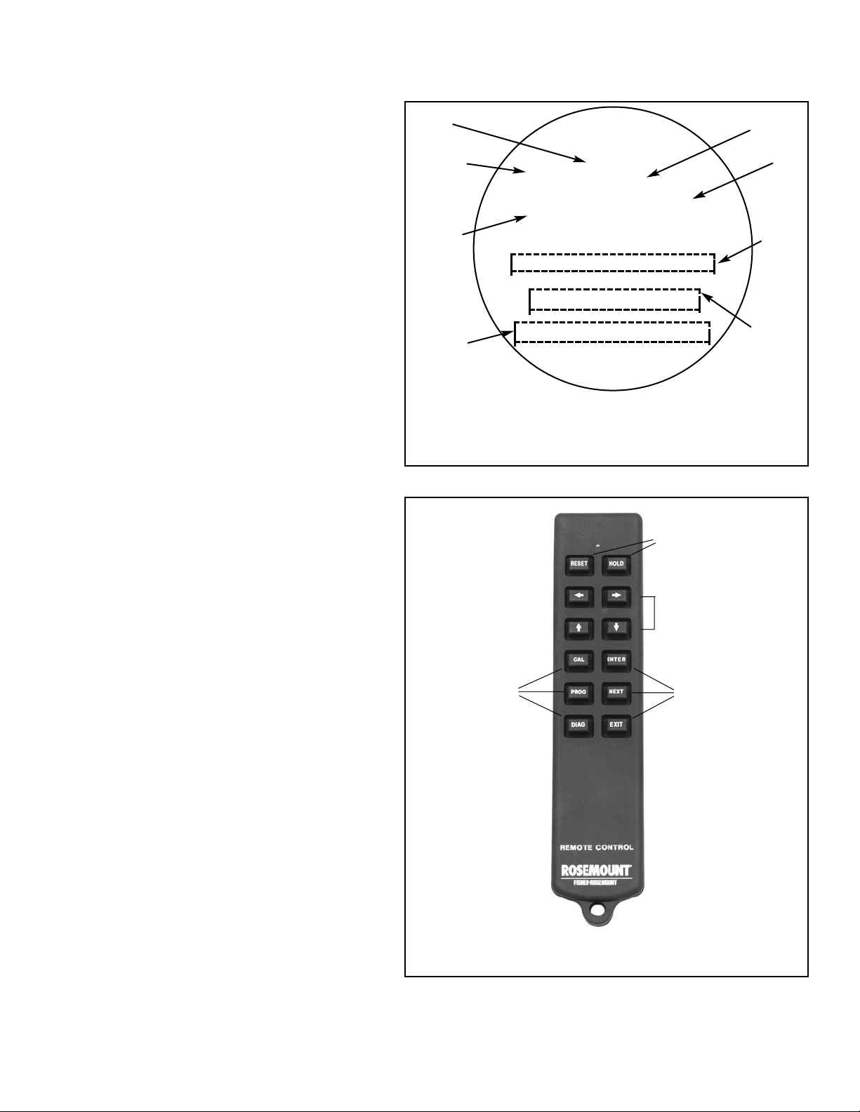
1.5 INFRARED REMOTE CONTROLLER
(FIGURE 1-2)
1. Pressing a menu key allows the user access to
calibrate, program, or diagnostic menus.
2. Press ENTER to store data and settings. Press
NEXT to move from one submenu to the next.
Press EXIT to leave without storing changes.
3. Use the editing arrow keys to scroll through lists
of allowed settings or to change a numerical setting to the desired value.
4. Pressing HOLD puts the transmitter in hold and
sends the output current to a pre-programmed
value. Pressing RESET causes the transmitter
to abandon the present menu operation and
return to the main display.
FIGURE 1-2. INFRARED REMOTE CONTROLLER
1.
4.
3.
2.
CALIBRATE PROGRAM DIAGNOSE
/-[5ES-U1
EXIT NEXT ENTER
mS/cm
F
A
U
L
T
H
O
L
D
6
7
8
3
4
1
2
5
FIGURE 1-1. TRANSMITTER DISPLAY DURING
CALIBRATION AND PROGRAMMING
The program display screen allows access to calibration and
programming menus.
♥
#"c""
Page 11
5
MODEL 5081-T SECTION 1.0
DESCRIPTION AND SPECIFICATIONS
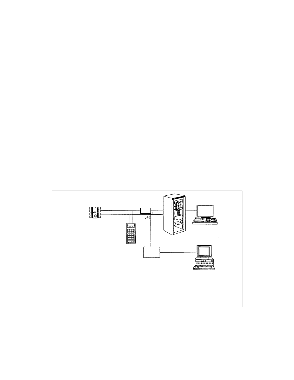
1.6 HART COMMUNICATIONS
1.6.1 OVERVIEW OF HART COMMUNICATION
HART (highway addressable remote transducer) is a digital communication system in which two frequencies are superimposed on the 4 to 20 mA output signal from the transmitter. A 1200 Hz sine wave represents the digit 1, and a 2400 Hz
sine wave represents the digit 0. Because the average value of a sine wave is zero, the digital signal adds no dc component to the analog signal. HART permits digital communication while retaining the analog signal for process control.
The HART protocol, originally developed by Fisher-Rosemount, is now overseen by the independent HART
Communication Foundation. The Foundation ensures that all HART devices can communicate with one another. For more
information about HART communications, call the HART Communication Foundation at (512) 794-0369. The internet
address is http://www.hartcomm.org.
1.6.2 HART INTERFACE DEVICES
HART communicators allow the user to view measurement data (pH, ORP and temperature), program the transmitter, and
download information from the transmitter for transfer to a computer for analysis. Downloaded information can also be sent
to another HART transmitter. Either a hand-held communicator, such as the Rosemount Model 375, or a computer can be
used. HART interface devices operate from any wiring termination point in the 4 - 20 mA loop. A minimum load of 250 ohms
must be present between the transmitter and the power supply. See Figure 1-3.
If your communicator does not recognize the Model 5081-T transmitter, the device description library may need updating.
Call the manufacturer of your HART communication device for updates.
4-20 mA + Digital
250
ohm
Control System
Computer
Model 5081-T-HT
Two-wire
Transmitter
Bridge
Hand Held
Communicator
(“Configurator”)
FIGURE 1-3. HART Communicators.
Both the Rosemount Model 375 (or 275) and a computer can be used to communicate
with a HART transmitter. The 250 ohm load (minimum) must be present between the
transmitter and the power supply.
Page 12
6
MODEL 5081-T SECTION 1.0
DESCRIPTION AND SPECIFICATIONS
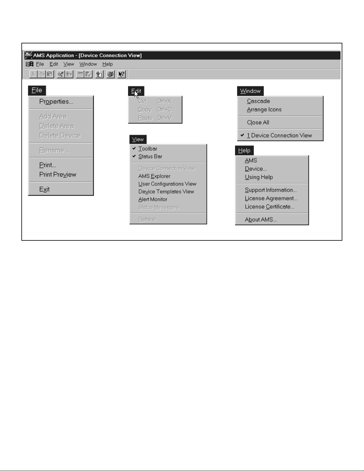
1.8 ASSET MANAGEMENT SOLUTIONS
Asset Management Solutions (AMS) is software that helps plant personnel better monitor the performance of analytical
instruments, pressure and temperature transmitters, and control valves. Continuous monitoring means maintenance personnel can anticipate equipment failures and plan preventative measures before costly breakdown maintenance is
required.
AMS uses remote monitoring. The operator, sitting at a computer, can view measurement data, change program settings,
read diagnostic and warning messages, and retrieve historical data from any HART-compatible device, including the Model
5081-T transmitter. Although AMS allows access to the basic functions of any HART compatible device, Rosemount
Analytical has developed additional software for that allows access to all features of the Model 5081-T transmitter.
AMS can play a central role in plant quality assurance and quality control. Using AMS Audit Trail, plant operators can track
calibration frequency and results as well as warnings and diagnostic messages. The information is available to Audit Trail
whether calibrations were done using the infrared remote controller, the Model 375 HART communicator, or AMS software.
AMS operates in Windows 95. See Figure 1-5 for a sample screen. AMS communicates through a HART-compatible
modem with any HART transmitters, including those from other manufacturers. AMS is also compatible with
FOUNDATION™ Fieldbus, which allows future upgrades to Fieldbus instruments.
Rosemount Analytical AMS windows provide access to all transmitter measurement and configuration variables. The
user can read raw data, final data, and program settings and can reconfigure the transmitter from anywhere in the plant.
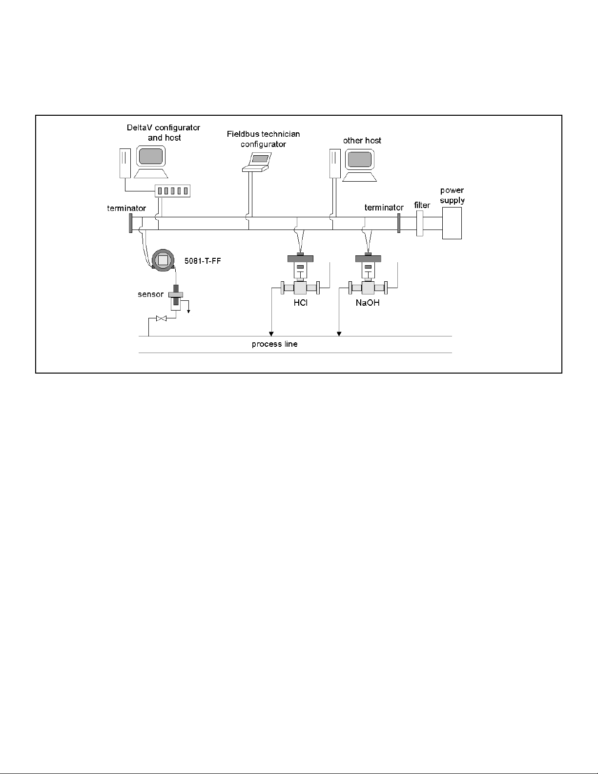
1.7 FOUNDATION FIELDBUS
Figure 1-4 shows a 5081-T-FF being used to measure conductivity. The figure also shows three ways in which Fieldbus
communication can be used to read process variables and configure the transmitter.
FIGURE 1-4. CONFIGURING MODEL 5081-T TRANSMITTER WITH F
OUNDATION
FIELDBUS
Page 13
MODEL 5081-T SECTION 1.0
DESCRIPTION AND SPECIFICATIONS
FIGURE 1-5. AMS MAIN MENU TOOLS
7
Page 14

8
MODEL 5081-T SECTION 2.0
INSTALLATION
SECTION 2.0
INSTALLATION
2.1 Unpacking and Inspection
2.2 Orienting the Display Board
2.3 Mechanical Installation
2.4 Power Supply/Current Loop — Model 5081-T-HT
2.5 Power Supply Wiring for Model 5081-T-FF/FI
2.1 UNPACKING AND INSPECTION
Inspect the shipping container. If it is damaged, contact the shipper immediately for instructions. Save the box. If there is
no apparent damage, remove the transmitter. Be sure all items shown on the packing list are present. If items are missing, immediately notify Rosemount Analytical.
Save the shipping container and packaging. They can be reused if it is later necessary to return the transmitter to the factory.
2.2 ORIENTING THE DISPLAY BOARD
The display board can be rotated 90 degrees, clockwise or counterclockwise, from the original position. To reposition the
display:
1. Loosen the cover lock nut until the tab disengages from the circuit end cap. Unscrew the cap.
2. Remove the three bolts holding the circuit board stack.
3. Lift and rotate the display board 90 degrees, clockwise or counterclockwise, into the desired position.
4. Position the display board on the stand offs. Replace and tighten the bolts.
5. Replace the circuit end cap.
2.3 MECHANICAL INSTALLATION
2.3.1 General information
1. The transmitter tolerates harsh environments. For best results, install the transmitter in an area where temperature
extremes, vibrations, and electromagnetic and radio frequency interference are minimized or absent.
2. To prevent unintentional exposure of the transmitter circuitry to the plant environment, keep the security lock in place
over the circuit end cap. To remove the circuit end cap, loosen the lock nut until the tab disengages from the end cap,
then unscrew the cover.
3. The transmitter has two 3/4-inch conduit openings, one on each side of the housing. Run sensor cable through the left
side opening (as viewed from the wiring terminal end of the transmitter) and run power wiring through the right side
opening.
4. Use weathertight cable glands to keep moisture out of the transmitter.
5. If conduit is used, plug and seal the connections at the transmitter housing to prevent moisture from getting inside the
transmitter.
NOTE
Moisture accumulating in the transmitter housing can affect the performance of the transmitter and may void the warranty.
6. If the transmitter is installed some distance from the sensor, a remote junction box with preamplifier in the junction box
or in the sensor may be necessary. Consult the sensor instruction manual for maximum cable lengths.
Page 15
9
MODEL 5081-T SECTION 2.0
INSTALLATION
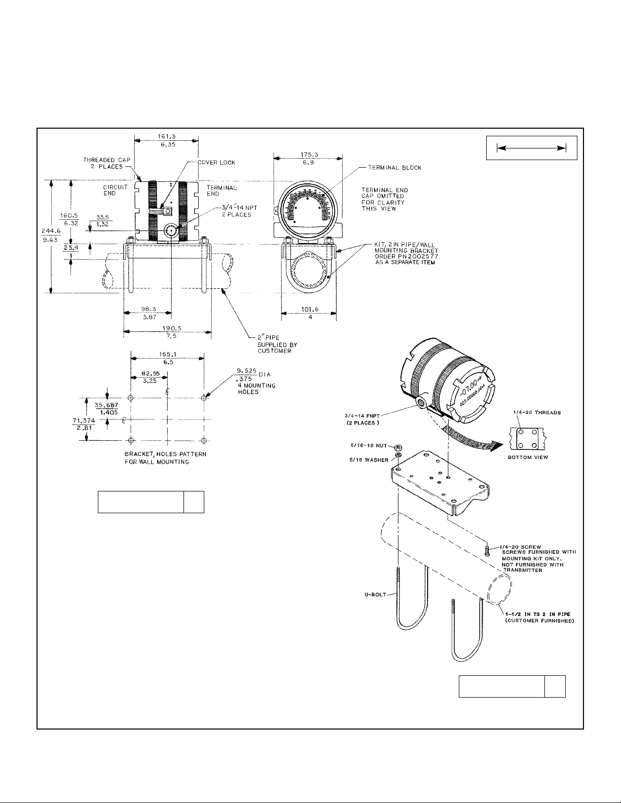
FIGURE 2-1. Mounting the Model 5081-T Toroidal Conductivity Transmitter on a Flat Surface
MILLIMETER
INCH
2.3.2 Mounting on a Flat Surface.
See Figure 2-1.
Page 16
10
MODEL 5081-T SECTION 2.0
INSTALLATION
FIGURE 2-2. Using the Pipe Mounting Kit to Attach the Model 5081-T Conductivity Transmitter to a Pipe
MILLIMETER
INCH
2.3.3 Pipe Mounting.
See Figure 2-2. The pipe mounting kit (PN 2002577) accommodates 1-1/2 to 2 in. pipe.
DWG. NO. REV.
40308104 G
DWG. NO. REV.
40308103 C
Page 17

11
MODEL 5081-T SECTION 2.0
INSTALLATION
TABLE 2-1. Model 5081-T Sensor Selection
2.3.4 Inductive Loops.
The Model 5081-T conductivity transmitter is designed to make accurate measurements while in contact with the process
stream. Measurements can also be tailored to high temperature and/or high pressure streams.
2.3.5 Sensor Selection.
All Rosemount Analytical contacting conductivity sensors with PT100 RTD or PT1000 RTD are compatible with the Model
5081-T transmitter. Please refer to Figures 3-5 thru 3-7 for appropriate sensor to transmitter wiring. The sensor cable
should be routed through the left inlet closest to the connector.
Choose an inductive conductivity sensor that is appropriate for your process conditions and range of conductivity measurement.
NOTE: Values shown are for 25°C conductivity with a temperature slope of 2% per
degree C. The maximum range value will be lower for solutions with a higher
temperature slope. Minimum conductivity depends on sensor.
RECOMMENDED RANGES FOR TOROIDAL SENSORS
Conductivity Sensor
Model Number 226 228 225 222 (1in.) 222 (2 in.) 242
Nominal Cell Constant 1.0 3.0 3.0 6.0 4.0 *
Min. Conductivity (µµS/cm) 50 200 200 500 500 100*
Max. Conductivity (µµS/cm) 1,000,000 2,000,000 2,000,000 2,000,000 2,000,000 2,000,000*
* Model 242 values depend on sensor configuration and wiring.
RECOMMENDED SENSORS:
Model 222 Flow-Through
Model 225 Clean-In-Place (CIP)
Model 226 Submersion/
Insertion
Model 228 Submersion/
Insertion/
Retractable
Model 242 Flow-Through*
* Model 242-06 or 242-08 with 5081T
do not have Intrinsically Safe
approvals.
Page 18
12
MODEL 5081-T SECTION 2.0
INSTALLATION
2.4 POWER SUPPLY/CURRENT LOOP
— MODEL 5081-T-HT
2.4.1 Power Supply and Load Requirements.
Refer to Figure 2-3.
The minimum power supply voltage is 12.5 Vdc
and the maximum is 42.4 Vdc. The top line on the
graph gives the voltage required to maintain at
least 12.5 Vdc at the transmitter terminals when
the output signal is 22 mA. The lower line is the
supply voltage required to maintain a 30 Vdc terminal voltage when the output signal is 22 mA.
The power supply must provide a surge current during the first 80 milliseconds of start-up. For a 24 Vdc
power supply and a 250 ohm load resistor the surge
current is 40 mA. For all other supply voltage and
resistance combinations the surge current is not
expected to exceed 70 mA.
For digital (HART or AMS) communications, the load must be at least 250 ohms. To supply the 12.5 Vdc lift off voltage at
the transmitter, the power supply voltage must be at least 18 Vdc.
For intrinsically safe operation the supply voltage should not exceed 30.0 Vdc.
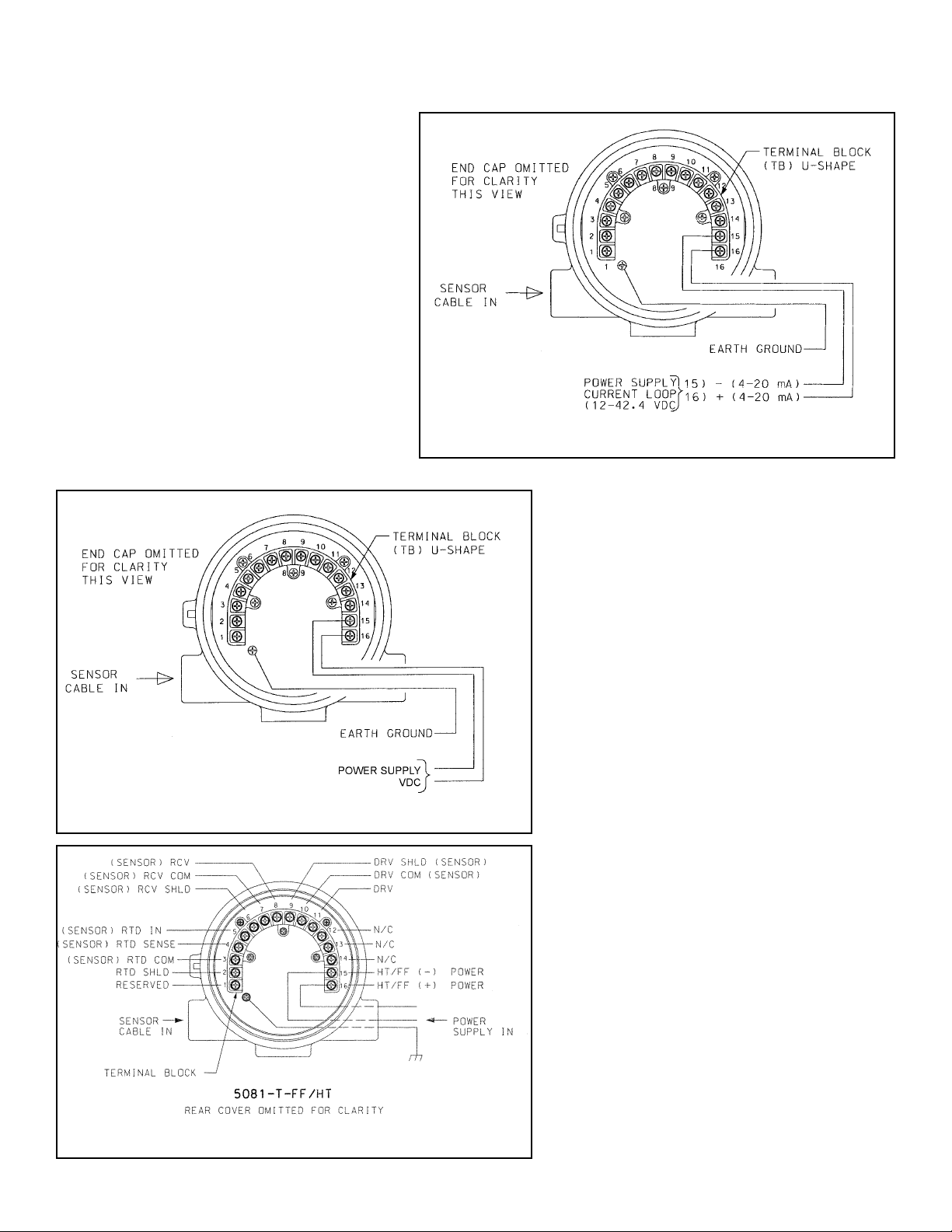
2.4.2 Power Supply-Current Loop Wiring. Refer to Figure 2-4.
Run the power/signal wiring through the
opening nearest terminals 15 and 16. Use
shielded cable and ground the shield at the
power supply. To ground the transmitter,
attach the shield to the grounding screw on
the inside of the transmitter case. A third
wire can also be used to connect the transmitter case to earth ground.
NOTE
For optimum EMI/RFI immunity, the
power supply/output cable should be
shielded and enclosed in an earthgrounded metal conduit.
Do not run power supply/signal wiring in
the same conduit or cable tray with AC
power lines or with relay actuated signal
cables. Keep power supply/ signal wiring at
least 6 ft (2 m) away from heavy electrical
equipment.
An additional 0-1 mA current loop is available between TB-14 and TB-15. A 1 mA current in this loop signifies a sensor fault. See
Section 3.0 for wiring instructions. See
Section 8.4 or 10.6 and Section 12.0 for
more information about sensor faults.
FIGURE 2-3. Load/Power Supply Requirements
FIGURE 2-4. Model 5081-T-HT Power Wiring Details
Page 19
13
MODEL 5081-T SECTION 2.0
INSTALLATION
2.5 POWER SUPPLY WIRING FOR
MODEL 5081-T-FF/FI
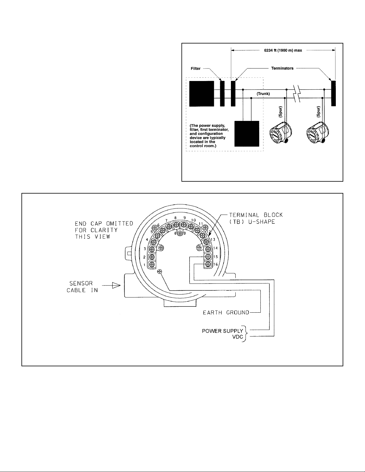
2.5.1 Power Supply Wiring. Refer to Figure 2-5 and
Figure 2-6.
Run the power/signal wiring through the opening nearest
terminals 15 and 16. Use shielded cable and ground the
shield at the power supply. To ground the transmitter,
attach the shield to the grounding screw on the inside of
the transmitter case. A third wire can also be used to connect the transmitter case to earth ground.
NOTE
For optimum EMI/RFI immunity, the power supply/output cable should be shielded and
enclosed in an earth-grounded metal conduit.
Do not run power supply/signal wiring in the same conduit or cable tray with AC power lines or with relay actuated signal cables. Keep power supply/signal wiring at
least 6 ft (2 m) away from heavy electrical equipment.
FIGURE 2-5. Typical Fieldbus Network Electrical
Wiring Configuration
FIGURE 2-6. Model 5081-T-FF Power Wiring Details
5081-T
Transmitter
5081-T
Transmitter
9 - 32
Page 20
14
MODEL 5081-T SECTION 3.0
WIRING
SECTION 3.0
WIRING
3.1 Sensor Wiring
3.2 Electrical Installation
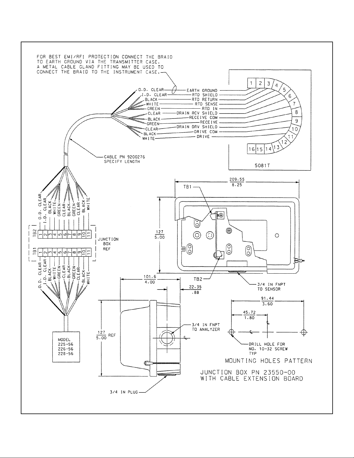
3.1.1 WIRING THROUGH A JUNCTION BOX
The sensor can be wired to the analyzer through a remote junction box (PN 23550-00). Wire the extension cable and sensor cable point-to-point. Refer to the sensor instruction manual for more details.
Factory-terminated (PN 23294-05) and unterminated (PN 9200276) connecting cable are available. The use of factory-terminated cable is strongly recommended. To prepare unterminated cable for use, follow the instructions in the sensor instruction
manual.
For maximum EMI/RFI protection, the outer braid of the sensor cable should be connected to the outer braided shield of
the extension cable. At the instrument, connect the outer braid of the extension cable to earth ground.
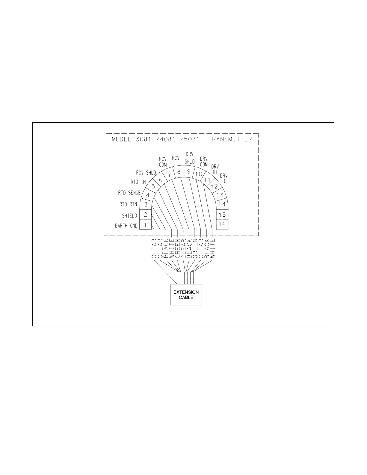
3.1 SENSOR WIRING
Wire sensor as shown below in Figure 3-1. Keep sensor wiring separate from power wiring. For best EMI/RFI protection,
use shielded output signal cable in an earth-grounded metal conduit. Refer to the sensor instruction manual for more
details.
FIGURE 3-1. Wiring Model 5081T-HT
Page 21
15
MODEL 5081-T SECTION 3.0
WIRING
3.1.2 POWER WIRING MODEL 5081-T-HT
For general purpose areas, wire power as shown
in Figure 3-2. For hazardous areas, please see
hazardous area installation drawings.
FIGURE 3-2. Power Supply/Current Loop Wiring for Model 5081-T-HT
3.1.3 POWER WIRING MODEL 5081-T-FF
For general purpose areas, wire power as shown
in Figure 3-3. For hazardous areas, please see
hazardous area installation drawings.
FIGURE 3-3. Power Supply/Current Loop Wiring for Model 5081-T-FF
FIGURE 3-4. Power Supply and Sensor Wiring for Model 5081-T
9 - 32
Page 22
16
MODEL 5081-T SECTION 3.0
WIRING
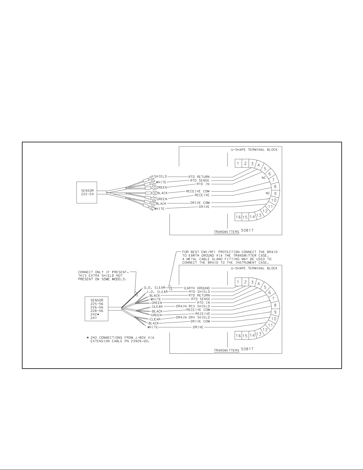
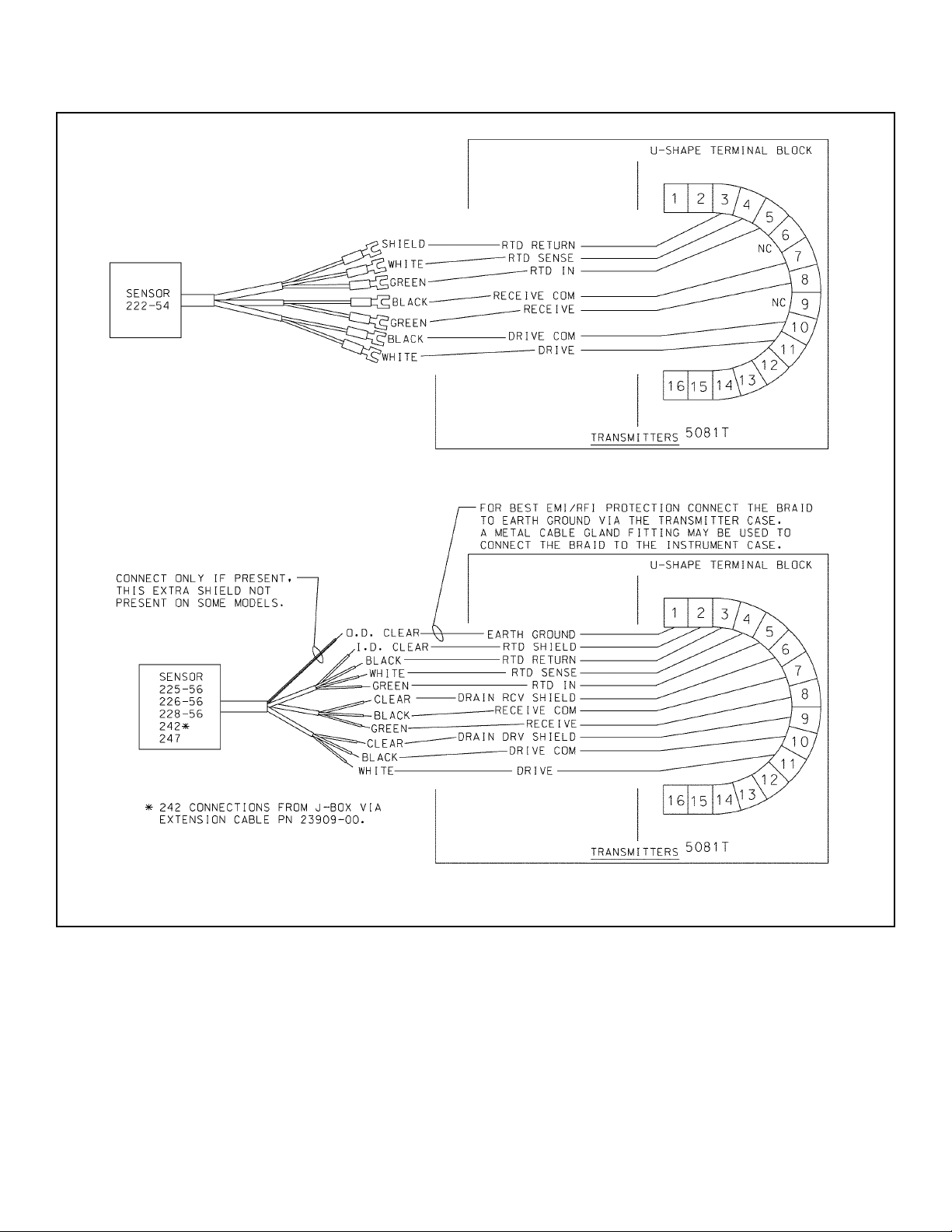
3.2 ELECTRICAL INSTALLATION
All Rosemount Analytical contacting conductivity sensors with PT100 RTD or PT1000 RTD are compatible with the Model
5081-T transmitter. Please refer to Figures 3-5 thru 3-7 for appropriate sensor to transmitter wiring. The sensor cable
should be routed through the left inlet closest to the connector.
NOTE
Optimum EMI/RFI immunity may be achieved on sensors whose interconnecting cable has an outer braided shield by
utilizing a cable gland fitting that provides for continuity between the braided shield and the transmitter enclosure. An
equivalent conduit connector may also be used if the sensor cable is to be enclosed in conduit.
FIGURE 3-5. Wiring Model 242 sensor to Model 5081-T transmitter
Page 23
MODEL 5081-T SECTION 3.0
WIRING
FIGURE 3-6. Wiring Models 222, 225, 226, 228, 242, & 247 sensors to Model 5081-T transmitter
17
Page 24
18
MODEL 5081-T SECTION 3.0
WIRING
FIGURE 3-7. Wiring Models 222, 225, 226, & 228 sensors to Model 5081-T transmitter
Page 25
MODEL 5081-T SECTION 4.0
INTRINSICALLY SAFE & EXPLOSION PROOF
SECTION 4.0
INTRINSICALLY SAFE & EXPLOSION PROOF
19
FIGURE 4-1. Model 5081-T-HT Infrared Remote Control — CSA, FM, & Baseefa/ATEX approvals
FIGURE 4-2. Model 5081-T-FF/FI Infrared Remote Control — CSA, FM, & Baseefa/ATEX approvals
REMOTE CONTROL
INTRINSICALLY SAFE EQUIPMENT
HAZARDOUS AREA LOCATIONS:
CLASS I, DIV 1, GP A, B, C, D
CLASS I, DIV 2, GP A, B, C, D
T3C Tamb = 40°C T3 Tamb = 80°C
1.5Vdc AAA BATTERIES
EVEREADY E92/1212
DURACELL MN2400/PC2400
IS/I/1/A,B,C & D
NI/I/2/A,B,C & D
T4 Tamb = 40°C
T3A Tamb = 80°C
Baseefa02ATEX0198
II 1G EExia IIC T4 1180
1.5Vdc AAA BATTERIES
EVEREADY E92/1212
DURACELL MN2400/PC2400
ROSEMOUNT ANALYTICAL 92606 USA
WARNING:
TO PREVENT IGNITION
CHANGE BATTERIES IN
A NONHAZARDOUS AREA
ONLY
IRC - INFRARED REMOTE CONTROL
LR 34186
Exia
SUBSTITUTION OF
COMPONENTS MAY
IMPAIR INTRINSIC SAFETY
PN 23572-00
YEAR
Page 26
20
MODEL 5081-T SECTION 4.0
INTRINSICALLY SAFE & EXPLOSION PROOF
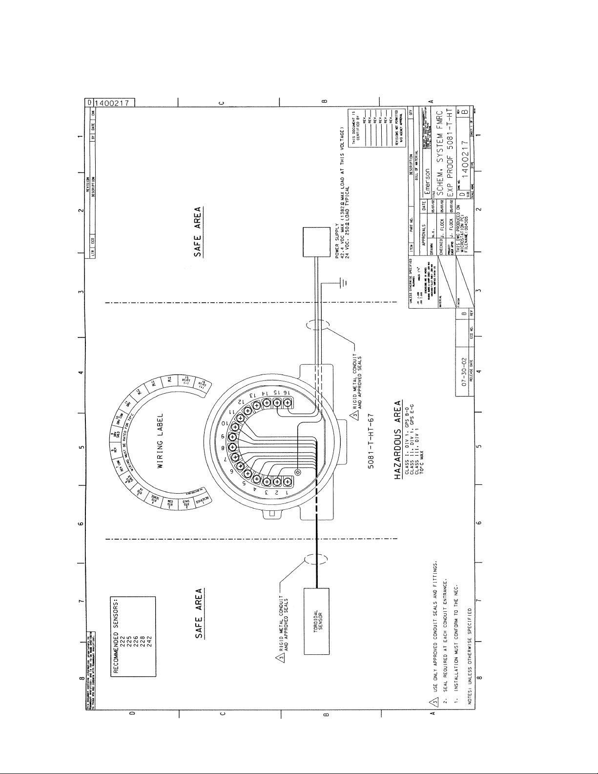
FIGURE 4-3. FM Explosion-Proof Installation for Model 5081-T-HT
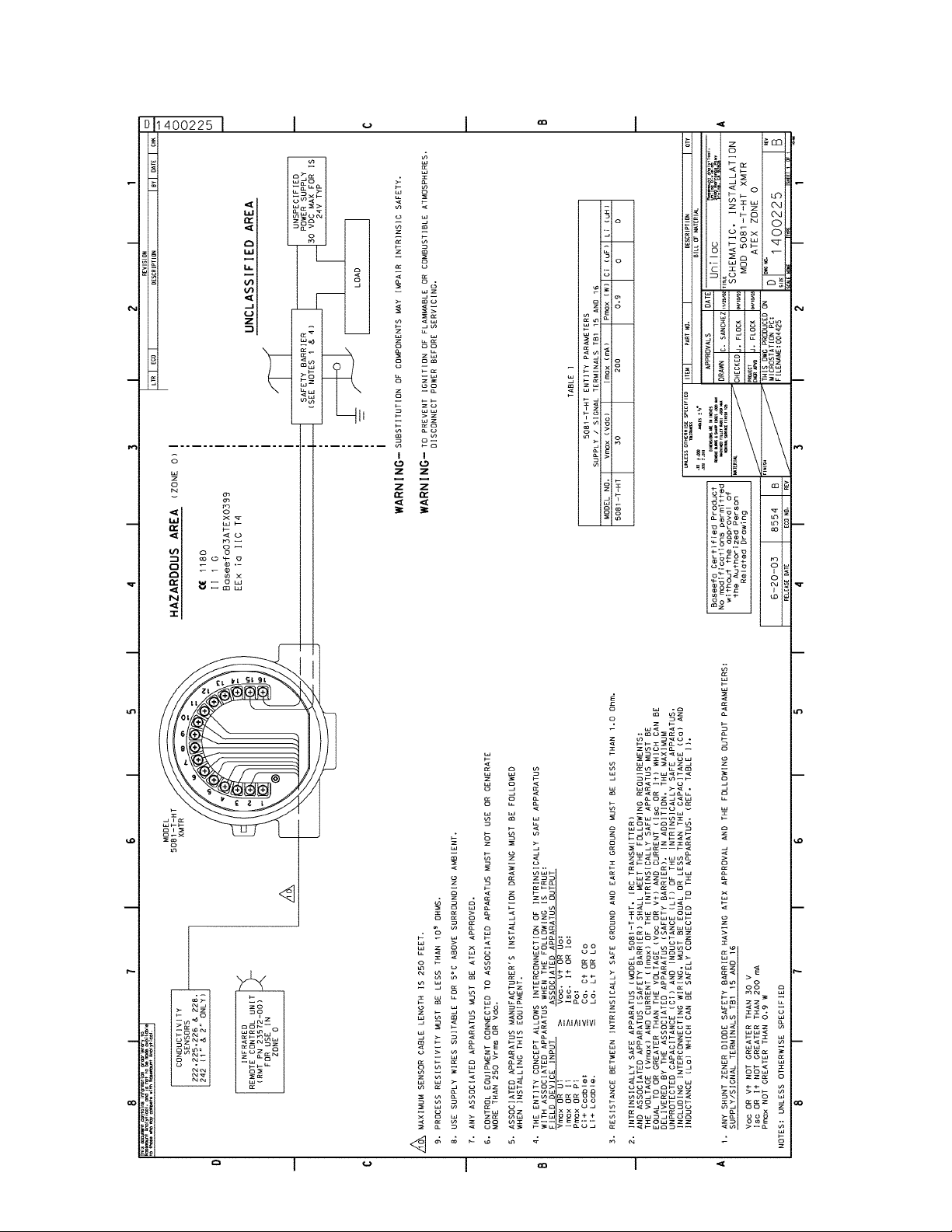
4.1 INTRINSICALLY SAFE AND EXPLOSION-PROOF INSTALLATION FOR MODEL 5081-T-HT
Page 27
MODEL 5081-T SECTION 4.0
INTRINSICALLY SAFE & EXPLOSION PROOF
21
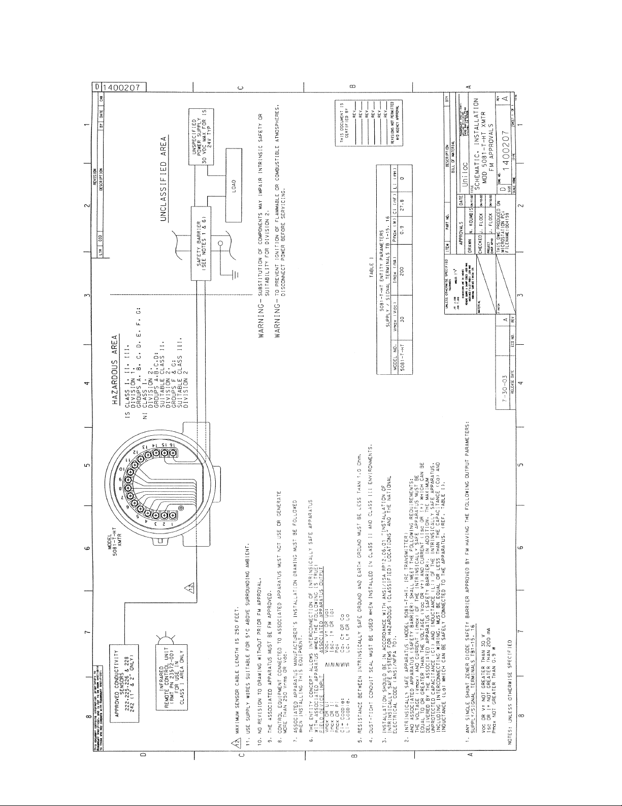
FIGURE 4-4. FM Intrinsically Safe Installation for Model 5081-T-HT
Page 28
22
MODEL 5081-T SECTION 4.0
INTRINSICALLY SAFE & EXPLOSION PROOF
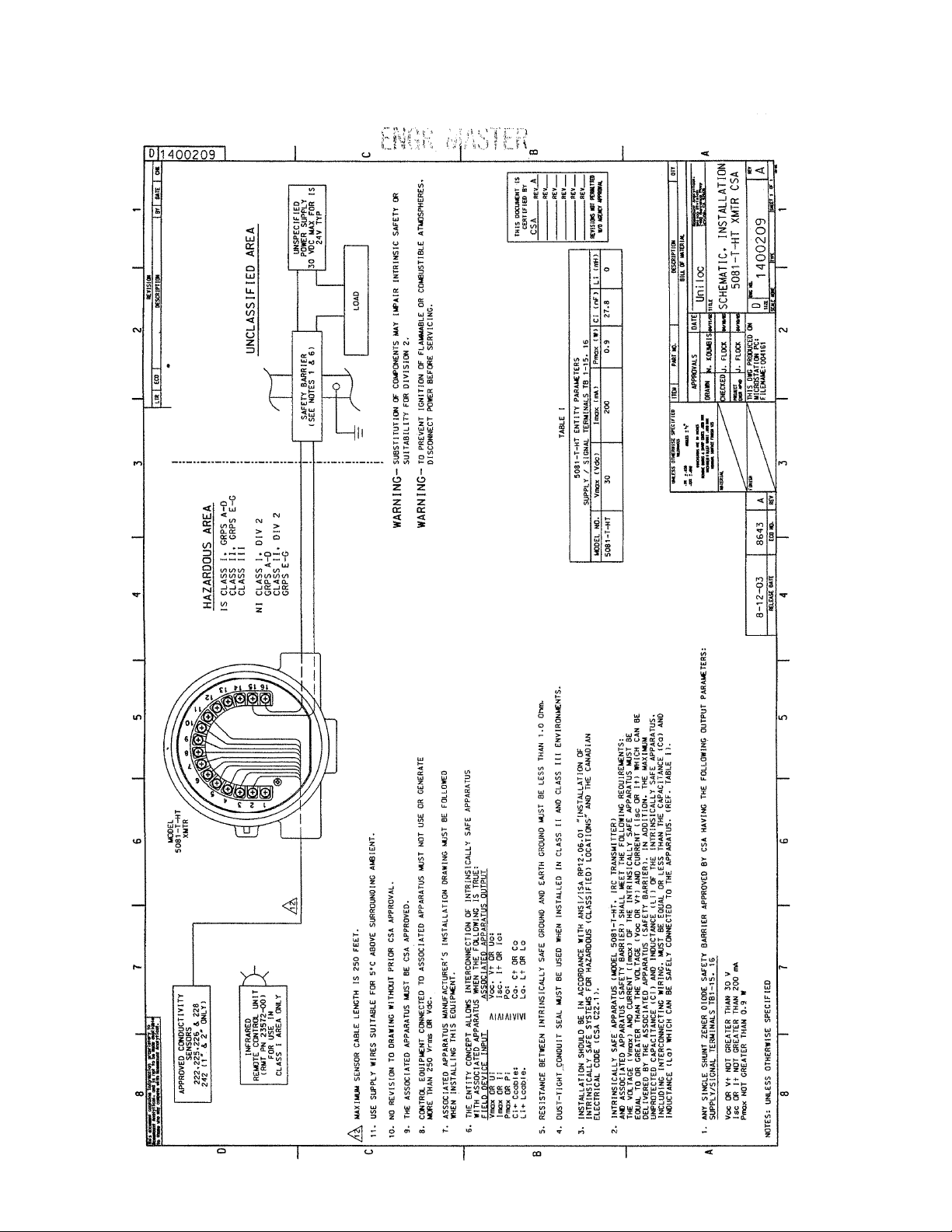
FIGURE 4-5. CSA Intrinsically Safe Installation for Model 5081-T-HT
Page 29
MODEL 5081-T SECTION 4.0
INTRINSICALLY SAFE & EXPLOSION PROOF
23
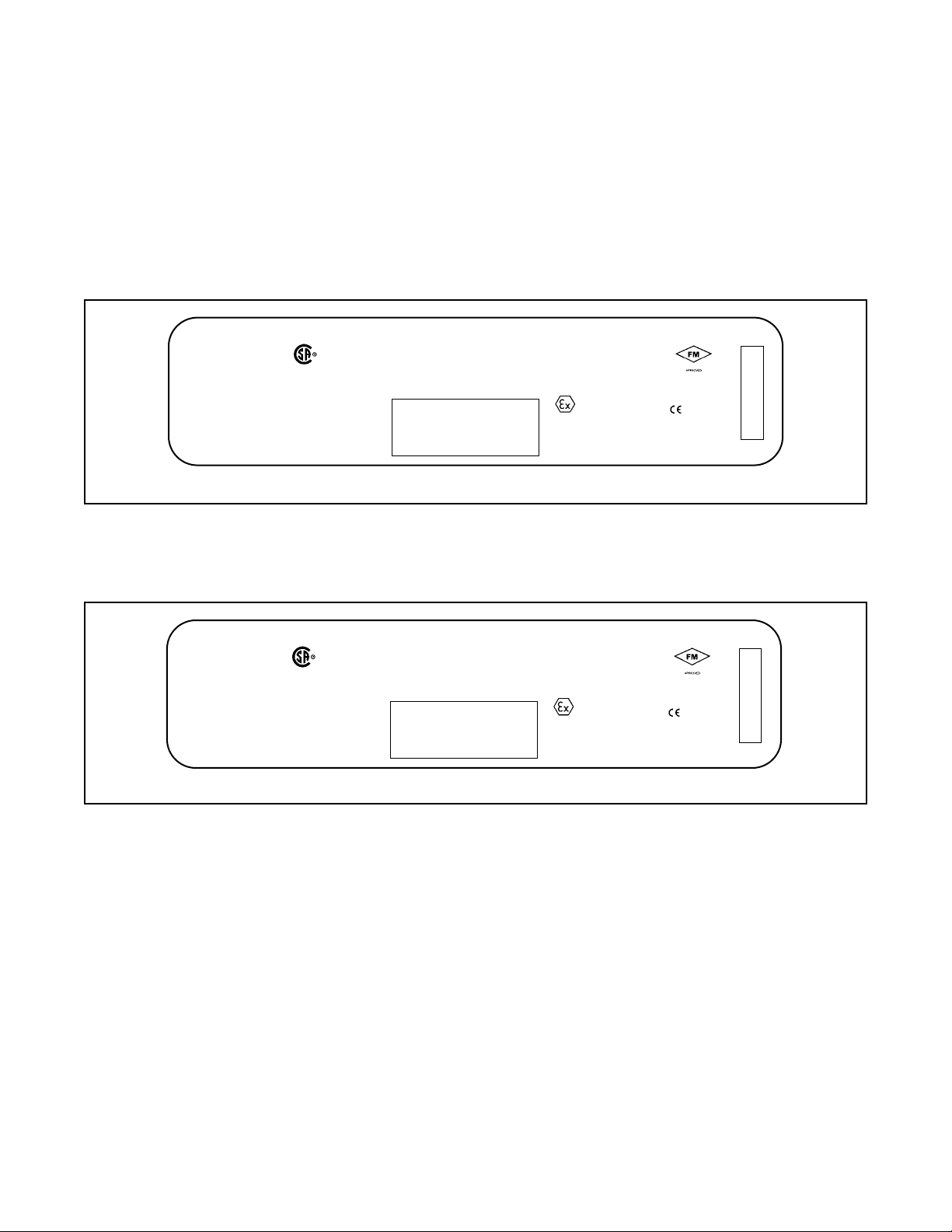
FIGURE 4-6. ATEX Intrisically Safe Label for Model 5081-T-HT
Page 30
24
MODEL 5081-T SECTION 4.0
INTRINSICALLY SAFE & EXPLOSION PROOF
FIGURE 4-7. ATEX Intrisically Safe Label for Model 5081-T-HT
Page 31
MODEL 5081-T SECTION 4.0
INTRINSICALLY SAFE & EXPLOSION PROOF
25
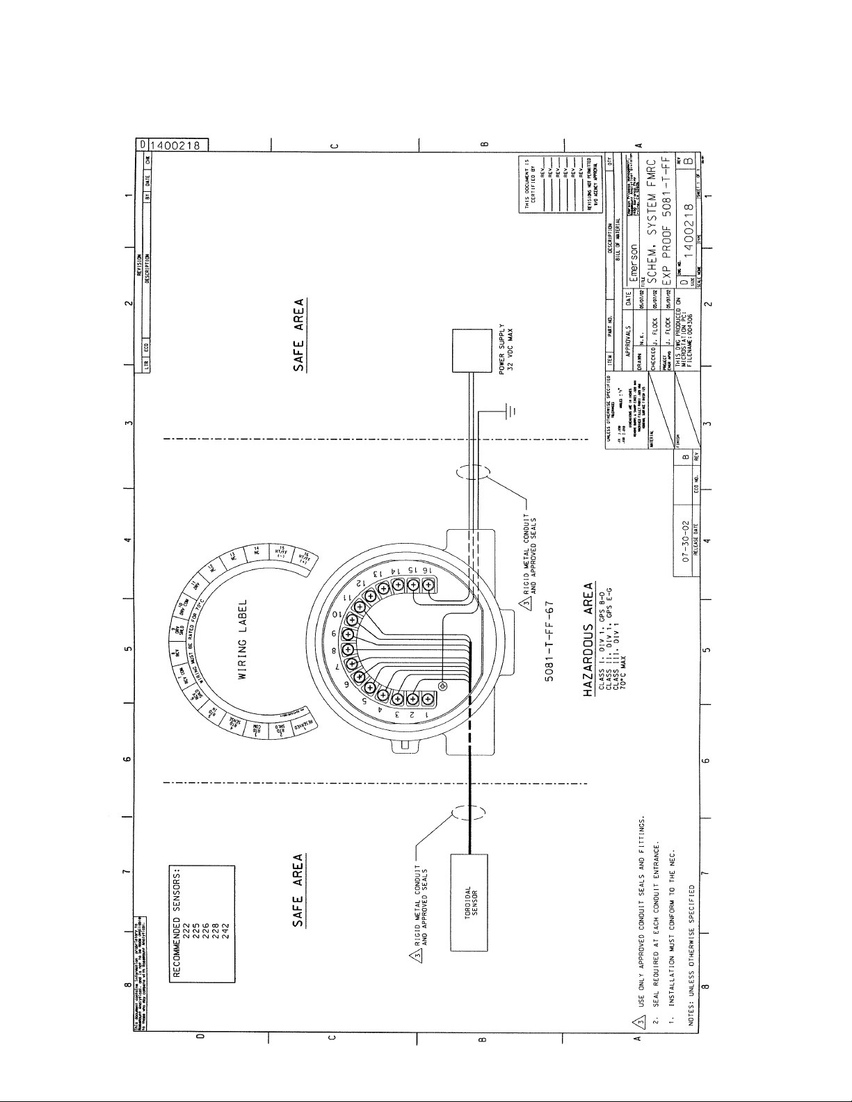
FIGURE 4-8. FM Explosion-Proof Installation for Model 5081-T-FF
4.2 INTRINSICALLY SAFE AND EXPLOSION-PROOF INSTALLATION FOR MODEL 5081-T-FF
Page 32

26
MODEL 5081-T SECTION 4.0
INTRINSICALLY SAFE & EXPLOSION PROOF
FIGURE 4-9. FM Intrinsically Safe Installation for Model 5081-T-FF
Page 33

MODEL 5081-T SECTION 4.0
INTRINSICALLY SAFE & EXPLOSION PROOF
27
FIGURE 4-10. CSA Intrinsically Safe Installation for Model 5081-T-FF
Page 34

28
MODEL 5081-T SECTION 4.0
INTRINSICALLY SAFE & EXPLOSION PROOF
FIGURE 4-11. ATEX Intrisically Safe Label for Model 5081-T-FF
Page 35

MODEL 5081-T SECTION 4.0
INTRINSICALLY SAFE & EXPLOSION PROOF
29
FIGURE 4-12. ATEX Intrinsically Safe Installation for Model 5081-T-FF
Page 36

30
FIGURE 4-13. FM Explosion-Proof Installation for Model 5081-T-FI
4.3 INTRINSICALLY SAFE AND EXPLOSION-PROOF INSTALLATION FOR MODEL 5081-T-FI
MODEL 5081-T SECTION 4.0
INTRINSICALLY SAFE & EXPLOSION PROOF
D
1
2
3
4
5
1400298
CHK
DATE
BY
REVISION
DESCRIPTION
ECO
LTR
C
1
5
4
1
H
T
/
F
F
C
N
3
1
C
N
2
1
C
N
1
V
1
R
D
C
°
OM
0
C
1
0
V
7
R
D
OR
F
D
D
V
L
9
E
R
H
D
T
S
A
R
E
B
V
C
8
T
R
S
U
M
G
M
N
O
I
C
R
7
V
I
C
R
W
D
L
V
H
S
C
R
6
WIRING LABEL
N
I
D
T
R
5
E
S
N
E
S
D
T
R
M
O
C
4
D
T
R
3
1
6
(
-
H
)
T
/
F
F
(
+
)
12
15
16
14
13
11
10
9
8
7
6
5
P
N
9
2
4
1
5
2
0
-
0
0
/
A
R
E
S
E
R
V
S
H
E
L
D
D
1
R
T
D
2
4
3
21
B
REV
REV
REV
REV
REV
REV
CERTIFIED BY
THIS DOCUMENT IS
FM A
POWER SUPPLY
17.5 VDC MAX
RIGID METAL CONDUIT
AND APPROVED SEALS
3
5081-T-FI-67
REVISIONS NOT PERMITTED
HAZARDOUS AREA
W/O AGENCY APPROVAL
CLASS I, DIV 1, GPS B-D
QTY
DESCRIPTION
BILL OF MATERIAL
PART NO.
ITEM
TOLERANCES
UNLESS OTHERWISE SPECIFIED
CLASS III, DIV 1
CLASS II, DIV 1, GPS E-G
A
06-01
A
REV
1
1
SHEET OF
1
Rosemount Analytical Division
Emerson Process Management,
2400 Barranca Pkwy
Irvine, CA 92606
TYPE
1400298
EXP PROOF 5081-T-FI
DWG NO.
Emerson
SCHEM, SYSTEM FMRC
TITLE
DATE
5/6/04
5/3/04
J. FLOCK
B. JOHNSON
APPROVALS
CHECKED
DRAWN
1/2
-
+
ANGLES
DIMENSIONS ARE IN INCHES
NOMINAL SURFACE FINISH 125
MACHINED FILLET RADII .020 MAX
.030
.010
REMOVE BURRS & SHARP EDGES .020 MAX
-
+
-
+
.XX
.XXX
MATERIAL
NONE
D
SIZE
SCALE
5/6/04
2
J. FLOCK
SOLID EDGE
THIS DWG CREATED IN
ENGR APVD
PROJECT
3
FINISH
A
REVECO NO.
4
RELEASE DATE
5-6-04 8933
5
70°C MAX
6
6
7
SAFE AREA SAFE AREA
AND APPROVED SEALS
RIGID METAL CONDUIT
3
222
242
225
RECOMMENDED SENSORS:
228
8
Rosemount Analytical, and is not to be made available
This document contains information proprietary to
to those who may compete with Rosemount Analytical.
226
D
C
SENSOR
TOROIDAL
3 USE ONLY APPROVED CONDUIT SEALS AND FITTINGS.
2. SEAL REQUIRED AT EACH CONDUIT ENTRANCE.
B
A
7
8
1. INSTALLATION MUST CONFORM TO THE NEC.
NOTES: UNLESS OTHERWISE SPECIFIED
Page 37

31
FIGURE 4-14. FM Intrisically Safe Label for Model 5081-T-FI
MODEL 5081-T SECTION 4.0
INTRINSICALLY SAFE & EXPLOSION PROOF
REVISIONS
REV
CHK
DATE
BY
DESCRIPTION
ECO
LTR
A
A
QTY
Uniloc Division
2400 Barranca Pkwy
Irvine, CA 92606
Rosemount Analytical,
REV
REV
REV
REV
REV
REV
REV
12
SHEET OF
FM A
CERTIFIED BY
THIS DOCUMENT IS
W/O AGENCY APPROVAL
REVISIONS NOT PERMITTED
9241515-01
5081-T-FI
Uniloc
DATE
APPROVALS
LABEL, I.S. FM
TITLE
5/3/04
5/6/04J. FLOCK
B. JOHNSON
5/6/04
J. FLOCK
DWG NO
B
2:1
SIZE
SCALE
DESCRIPTION
BILL OF MATERIAL
PART NO
RELEASE DATE ECO NO
SOLID EDGE
ITEM
DRAWN
THIS DWG CREATED IN
PROJECT
ENGR APVD
CHECKED
±.02
1/2
-
5-6-04 8933
±.01 5
.120
Ø .125
FM
APPROVED
2.56
4 FINISH:SILKSCREEN BLACK EPOXY PAINT (BAKED).
±.00 5
2.180
±.015
.650
+
ANGLES
TOLERANCES
DIMENSIONS ARE IN INCHES
.030
.010
REMOVE BURRS & SHARP EDGES .020 MAX
-
+
-
+
UNLESS OTHERWISE SPECIFIED
.XX
.XXX
1
4
NOMINAL SURFACE FINISH 125
MACHINED FILLET RADII .020 MAX
MATERIAL
FINISH
±.02
R
Tamb= 70°C
1.30
.125
ROSEMOUNT ANALYTICAL
GRPS. A,B,C,D,E,F & G
CLASS I, II & III, DIV. 1,
INTRINSICALLY SAFE FOR
MODEL
5081-T-FI-67
T4
CONNECTED PER DWG. 14002 84
HAZARDOUS AREA WHEN
GRPS. E, F & G
CLASS II AND III, DI V. 1,
DUST IGNITION PROOF
NON-INCENDIVE
CLASS I, DIV. 2, GRPS . A,B,C & D
WARNING: COMPONENT SUBSTITUTION
MAY IMPAIR INTRINSIC SAFETY
OR SUITABILITY FOR DIV.2.
EXPLOSION PROOF
NEMA 4X ENCLOSURE.
9241515-01/A
CLASS II, DIV. 1, GRPS. E,F & G
PER DWG. 1400298
CLASS III, DIV. 1
CLASS I, DIV.1, GRPS. B,C & D
R .25
4X
±.005
2X FULL R
This document contains information proprietary to
to those who may compete with Rosemount Analytical.
Rosemount Analytical, and is not to be made available
.140
3. ARTWORK IS SHEET 2 OF 2.
2. NO CHANGE WITHOUT FM APPROVAL.
HARDNESS BRINELL 190.
BE ANNEALED & PASSIVATED. MAXIMUM
STEEL .015+/-.005 THICK. MATERIAL TO
1 MATERIAL: AISI 300 SERIES STAINLESS
NOTES: UNLESS OTHERWISE SPECIFIED
Page 38

32
FIGURE 4-15. FM Intrinsically Safe Installation for Model 5081-T-FI
MODEL 5081-T SECTION 4.0
INTRINSICALLY SAFE & EXPLOSION PROOF
D
1
2
3
4
1400284
CHK
DATE
BY
REVISION
DESCRIPTION
ECO
LTR
C
THIS DOCUMENT IS
APPARATUS
ASSOCIATED
ANY FM APPROVED
NON-HAZARDOUS LOCATIONS
ANY FM APPROVED
TERMINATOR
APPARATUS
ANY FM APPROVED
INTRINSICALLY SAFE
ANY FM APPROVED
SUBSTITUTION OF COMPONENTS MAY IMPAIR INTRINSIC SAFETY OR
SUITABILITY FOR DIVISION 2.
DISCONNECT POWER BEFORE SERVICING.
TO PREVENT IGNITION OF FLAMMABLE OR COMBUSTIBLE ATMOSPHERES,
WARNING-
WARNING-
TERMINATOR
B
REV
REV
REV
REV
CERTIFIED BY
FM B
REV
REV
W/O AGENCY APPROVAL
REVISIONS NOT PERMITTED
10
10
Li (uH)
5
5
Ci (nF)
2.52
5.32
Pmax (W)
360
380
Imax (mA)
TABLE I
17.5
17.5
Vmax (Vdc)
5081-T-FI FISCO PARAMETERS
SUPPLY / SIGNAL TERMINALS TB 1-15, 16
IIB/
IIC/
C,D,E,F,G
GROUPS
A,B,C,D,E,F,G
5081-T-FI
5081-T-FI
MODEL NO.
A
10-96
B
QTY
Uniloc Division
Rosemount Analytical,
2400 Barranca Pkwy
DESCRIPTION
BILL OF MATERIAL
Uniloc
DATE
PART NO.
APPROVALS
ITEM
1/2
-
+
ANGLES
TOLERANCES
DIMENSIONS ARE IN INCHES
.030
.010
REMOVE BURRS & SHARP EDGES .020 MAX
-
+
-
+
UNLESS OTHERWISE SPECIFIED
.XX
.XXX
REV
1
1
SHEET OF
Irvine, CA 92606
5081-T-FI XMTR
SCHEMATIC, INSTALLATION
TITLE
5/6/04
5/3/04
5/6/04
B. JOHNSON
J. FLOCK
J. FLOCK
PROJECT
DRAWN
CHECKED
NOMINAL SURFACE FINISH 125
MACHINED FILLET RADII .020 MAX
MATERIAL
1
TYPE
1400284
FM APPROVALS
DWG NO.
NONE
D
SIZE
SCALE
2
THIS DWG CREATED IN
SOLID EDGE
ENGR APVD
3
FINISH
B
REV
ECO NO.
8933
4
RELEASE DATE
5-6-04
IS CLASS I, II, III,
GROUPS A, B, C, D, E, F, G;
DIVISION 1,
NI CLASS I,
DIVISION 2
SUITABLE CLASS II,
GROUPS A,B,C,D;
SUITABLE CLASS III,
GROUPS F & G;
DIVISION 2,
DIVISION 2,
HAZARDOUS (CLASSIFIED) LOCATIONS
15
16
14
13
12
11
5
FISCO
6
7
10
9
8
7
6
5
4
3
21
XMTR
MODEL
5081-T-FI
FM INTRINSIC SAFETY INSTALLATION
10
/ISA RP12.06 "INSTALLATION OF INTRINSICALLY SAFE SYSTEMS
5
6
7
INFRARED
FOR USE IN
(RMT PN 23572-00)
CLASS I AREA ONLY
REMOTE CONTROL UNIT
°C ABOVE SURROUNDING AMBIEN T.
Ca, Ct OR Co
La, Lt OR Lo; OR Lc/Rc (La/Ra OR Lo/Ro) AND Li/Ri (La/Ra OR Lo/Ro)
APPROVED CONDUCTIVITY
SENSORS
222,225,226 & 228
242 (1" & 2" ONLY)
8
Rosemount Analytical, and is not to be made available
This document contains information proprietary to
to those who may compete with Rosemount Anal ytical.
D
C
7. THE CONFIGURATION OF ASSOCIATED APPARATUS MUST BE FACTORY MUTUAL RESEARCH APPROVED
8. NO REVISION TO DRAWING WITHOUT PRIOR FACTORY MUTUAL RESEARCH APPROVAL.
9. USE SUPPLY WIRES SUITABLE FOR 5
10 MAXIMUM SENSOR CABLE LENGTH IS 250 FEET.
WHEN INSTALLING THIS EQUIPMENT.
WITH ASSOCIATED APPARATUS WHEN THE FOLLOWING IS TRUE:
5. ASSOCIATED APPARATUS MANUFACTURER'S INSTALLATION DRAWING MUST BE FOLLOWED
MORE THAN 250 Vrms OR Vdc.
UNDER THE ASSOCIATED CONCEPT.
6. CONTROL EQUIPMENT CONNECTED TO ASSOCIATED APPARATUS MUST NOT USE OR GENERATE
B
Vmax OR Ui Voc, Vt OR Uo;
3Ci+ 3Ccable;
Pmax OR Pi Po;
3Li + 3Lcable.
Imax OR Ii Isc, It OR Io;
FIELD DEVICE INPUT ASSOCIATED APPARATUS OUTPUT
4. THE ENTITY CONCEPT ALLOWS INTERCONNECTION OF INTRINSICALLY SAFE APPARATUS
1. INSTALLATION SHOULD BE IN ACCORDANCE WITH ANSI
2. DUST-TIGHT CONDUIT SEAL MUST BE USED WHEN INSTALLED IN CLASS II AND CLASS III ENVIRONMENTS.
3. RESISTANCE BETWEEN INTRINSICALLY SAF E GROUND AND EARTH GROUND MUST BE LESS THAN 1.0 Ohm .
A
FOR HAZARDOUS (CLASSIFIED) LOCATIONS" (EXCEPT CHAPTER 5 FOR FISCO INSTALLATIONS) AND THE NATIONAL ELECTRICAL
CODE (ANSI/NFPA 70) SECTIONS 504 AND 505.
8
NOTES: UNLESS OTHERWISE SPECIFIED
Page 39

33
FIGURE 4-16. CSA Intrisically Safe Label for Model 5081-T-FI
MODEL 5081-T SECTION 4.0
INTRINSICALLY SAFE & EXPLOSION PROOF
REVISIONS
REV
ECO NORELEASE DATE
CHK
DATE
BY
DESCRIPTION
ECO
LTR
A
8925
A
REV
A
REV
REV
REV
REV
REV
REV
QTY
Uniloc Division
2400 Barranca Pkw y
Rosemount Analytical,
Irvine, CA 92606
2
1
SHEET OF
CERTIFIED BY
CSA
THIS DOCUMENT IS
W/O AGENCY APPROVAL
REVISIONS NOT PERMITTED
LABEL, I.S. CSA
9241516-01
5081-T-FI
DESCRIPTION
2:1
DWG NO
Uniloc
TITLE
B
SIZE
SCALE
BILL OF MATERIAL
DATE
PART NO
5/3/04
B. JOHNSON
5/6/04
J. FLOCK
5/6/04
J. FLOCK
APPROVALS
SOLID EDGE
ITEM
DRAWN
THIS DWG CREATED IN
PROJECT
CHECKED
ENGR APVD
This document contains information proprietary to
Rosemount Analytical, and is not to be made available
5-6-04
Ø .125
to those who may compete with Rosemount Analytical.
R .25
4X
±.015.120
±.02
2.56
±.005
2.180
LR34186
ENCLOSURE 4
R
SA
R
Tamb= 70°C
ROSEMOUNT ANALYTICAL
INTRINSICALLY SAFE FOR
Exia ENTITY
5081-T-FI-69
MODEL
CLASS I, GRPS A, B, C & D
CLASS II, GRPS E, F & G
HAZARDOUS AREA WHEN CONNECTED
T3A Tamb = 70°C
CLASS III
WARNING: COMPONENT SUBSTITUTION
MAY IMPAIR INTRINSIC SAFETY.
PER DWG. 1400285
CLASS II, DIV. 2, GRPS E, F & G
SUITABLE FOR
CLASS I, DIV. 2, GRPS A,B,C & D
TION OF COMPONENTS MAY IMPAIR
WARNING-EXPLOSION HAZARD-SUBSTITU-
HAZARDOUS.
DISCONNECT WHILE CIRCUIT IS LIVE
SUITABILITY FOR CLASS I, DIV 2.
UNLESS AREA IS KNOWN TO BE NON-
WARNING-EXPLOSION HAZARD-DO NOT
T3A
CLASS I, GRPS B,C & D
CLASS III
CLASS II, GRPS E, F & G
WITHIN 50 mm OF THE ENCLOSURE.
ARE LIVE.
SEAL REQUIRED TO BE INSTALLED
KEEP COVER TIGHT WHILE CIRCUITS
Tamb ABOVE 60°C USE 75°C MINIMUM
RATED WIRING
Tamb = 65°C MAX
9241516-01/A
±.01 5.650
±.021.30
.125
1/2
-
+
4 FINISH:SILKSCREEN BLACK EPOXY PAINT (BAKED).
ANGLES
TOLERANCES
DIMENSIONS ARE IN INCHES
.030
.010
REMOVE BURRS & SHARP EDGES .020 MAX
-
+
-
+
UNLESS OTHERWISE SPECIF IED
.XX
.XXX
1
4
NOMINAL SURFACE FINISH 125
MACHINED FILLET RADII .020 MAX
MATERIAL
FINISH
.140
2X FULL R
STEEL .015+/-.005 THICK. MATERIAL TO
BE ANNEALED & PASSIVATED. MAXIMUM
HARDNESS BRINELL 190.
3. ARTWORK IS SHEET 2 OF 2.
2. NO CHANGE WITHOUT CSA APPROVAL.
1 MATERIAL: AISI 300 SERIES STAINLESS
NOTES: UNLESS OTHERWISE SPECIFIED
Page 40

34
FIGURE 4-17. CSA Intrinsically Safe Installation for Model 5081-T-FI
MODEL 5081-T SECTION 4.0
INTRINSICALLY SAFE & EXPLOSION PROOF
D
1
2
3
4
1400285
CHK
DATE
YBNOITPIR
REVISION
C
SED
ECO
LTR
HAZARDOUS AREA
CLASS II, GRPS E-G
IS CLASS I, GRPS A-D
C
THIS DOCUMENT IS
UNSPECIFIED
17.5 VDC MAX
POWER SUPPLY
UNCLASSIFIED AREA
CSA APPROVED
SUITABLE FOR FISCO
SEE NOTE 5 AND TABLE 1
ASSOICATED APPARATUS
DISCONNECT POWER BEFORE SERVICING.
SUITABILITY FOR DIVISION 2.
SUBSTITUTION OF COMPONENTS MAY IMPAIR INTRINSIC SAFETY OR
TO PREVENT IGNITION OF FLAMMABLE OR COMBUSTIBLE ATMOSPHERES,
WARNING-
WARNING-
GRPS A-D
CLASS II, DIV 2
GRPS E-G
CLASS III
NI CLASS I, DIV 2
B
A
REV
REV
REV
REV
REV
REV
CERTIFIED BY
CSA
W/O AGENCY APPROVAL
REVISIONS NOT PERMITTED
023
Li (mH)Vmax (Vdc)
27.8
Ci (nF)
.5
Pmax (W)
TABLE I
380
Imax (mA)
5081-T-FI ENTITY PARAMETERS
SUPPLY / SIGNAL TERMINALS TB 1-15, 16
17.5
5081-T-FI
MODEL NO.
A
10-96
A
TITLE
5/3/04
B. JOHNSON
DRAWN
NOMINAL SURFACE FINISH 125
MACHINED FILLET RADII .020 MAX
SCHEMATIC, INSTALLATION
5/6/04
J. FLOCK
PROJECT
CHECKED
MATERIAL
5081-T-FI XMTR CSA
5/6/04
J. FLOCK
ENGR APVD
REV
1
1
SHEET OF
1
TYPE
1400285
DWG NO.
NONE
D
SIZE
SCALE
2
SOLID EDGE
THIS DWG CREATED IN
3
FINISH
A
ECO NO. REV
8925
4
RELEASE DATE
5-6-04
QTY
Irvine, CA 92606
2400 Barranca Pkwy
Rosemount Analytical,
Uniloc Division
DESCRIPTION
BILL OF MATERIAL
Uniloc
DATE
PART NO.
APPROVALS
ITEM
1/2
-
+
ANGLES
TOLERANCES
DIMENSIONS ARE IN INCHES
.030
.010
REMOVE BURRS & SHARP EDGES .020 MAX
+
-
-
+
UNLESS OTHERWISE SPECIFIED
.XX
.XXX
15
16
14
13
12
11
FISCO
MODEL
5081-T-FI
10
9
8
7
6
5
4
3
12
XMTR
5
6
11
7
INFRARED
SENSORS
222,225,226 & 228
242 (1" & 2" ONLY)
APPROVED CONDUCTIVITY
FOR USE IN
(RMT PN 23572-00)
CLASS I AREA ONLY
REMOTE CONTROL UNIT
La, Lt OR Lo
Ca, Ct OR Co
8
5
6
7
8
CSA INTRINSIC SAFETY INSTALLATION
WHEN INSTALLING THIS EQUIPMENT .
Vmax OR Ui Voc, Vt OR Uo;
Ci+ Ccable;
Imax OR Ii Isc, It OR Io;
Pmax OR Pi Po;
Li+ Lcable.
FIELD DEVICE INPUT ASSOCIATED APPARAT US OUTPUT
to those who may compete with Rosemount Analytical.
This document contains information proprietary to
Rosemount Analytical, and is not to be made available
D
C
11 MAXIMUM SENSOR CABLE LENGTH IS 250 FEET.
MORE THAN 250 Vrms OR Vdc.
8. THE ASSOCIATED APPARATUS MUST BE CSA APPROVED.
7. CONTROL EQUIPMENT CONNECTED TO ASSOCIATED APPARATUS MUST NOT USE OR GENERAT E
9. NO REVISION TO DRAWING W ITHOUT PRIOR CSA APPROVAL.
10. USE SUPPLY WIRES SUITABLE FOR 5 °C ABOVE SURROUNDING AMBIENT.
WITH ASSOCIATED APPARATUS WHEN THE FOLLOWING IS TRUE:
6. ASSOCIATED APPARATUS MANUFACTURER'S INSTALLATION DRAW ING MUST BE FOLLOWED
5. THE ENTITY CONCEPT ALLOWS INTERCONNECTION OF INTRINSICALLY SAFE APPARATUS
3. DUST-TIGHT CONDUIT SEAL MUST BE USED W HEN INSTALLED IN CLASS II AND CLASS III ENVIRONMENTS.
4. RESISTANCE BETW EEN INTRINSICALLY SAFE GROUND AND EARTH GROUND MUST BE LE SS THAN 1.0 Ohm.
B
ELECTRICAL CODE (CSA C22.1).
INTRINSICALLY SAFE SYSTEMS FOR HAZARDOUS (CLASSIFIED) LOCATIONS" AND THE CANADIAN
2. INSTALLATION SHOULD BE IN ACCORDANCE WITH ANSI/ISA RP12.06.01 "INSTALL ATION OF
AND ASSOCIATED APPARATUS (SAFETY BARRIER) SHALL MEET THE FOLL OWING REQUIREMENTS:
1. INTRINSICALLY SAFE APPARATUS (MODEL 5081-T-FI, IRC TRANSMITTER)
THE VOLTAGE (Vmax) AND CURRENT (Ima x) OF THE INTRINSICALLY SAFE APPARATUS MUST BE
EQUAL TO OR GREATER THAN THE VOLTAGE (Voc OR Vt) AND CURRENT (Isc OR It) WHICH CAN BE
INDUCTANCE (La) WHICH CAN BE SAFELY CONNECTED TO THE APPARATUS . (REF. TABLE I).
INCLUDING INTERCONNECTING WIRING, MUST BE EQUAL OR LE SS THAN THE CAPACITANCE (Ca) AND
UNPROTECTED CAPACITANCE (Ci) AND INDUCTANCE (Li) OF THE INTRINSICALLY SAFE APPARATUS,
DELIVERED BY THE ASSOCIATED APPARATUS (SAFETY BARRIER). IN ADDITIO N, THE MAXIMUM
NOTES: UNLESS OTHERWISE SPECIFIED
A
Page 41

35
B
9241514 01
FIGURE 4-18. ATEX Intrisically Safe Label for Model 5081-T-FI
MODEL 5081-T SECTION 4.0
INTRINSICALLY SAFE & EXPLOSION PROOF
REVISIONS
REV
ECO NORELEASE DATE
CHK
DATE
BY
DESCRIPTION
ECO
LTR
A
8925
THIS DOCUMENT IS
CERTIFIED BY
A
REV
REV
Baseefa
REV
REV
REV
REV
REVISIONS NOT PERMITTED
21
A
QTY
Rosemount Analytical,
Uniloc Division
2400 Barranca Pkw y
Irvine, CA 92606
W/O AGENCY APPROVAL
Related Drawi ng
the Authorized Person
without the approval of
Baseefa Certified Product
No modifications permitted
DESCRIPTION
Uniloc
BILL OF MATERIAL
DATE
5/3/04
PART NO
ITEM
B. JOHNSON
APPROVALS
DRAWN
REV
SHEET OF
9241514-01
2:1
DWG NO
5081-T-FI
LABEL, I.S. BAS/ATEX
5/6/04
J. FLOCK
CHECKED
5/6/04
J. FLOCK
PROJECT
ENGR APVD
B
SIZE
SCALE
SOLID EDGE
THIS DWG CREATED IN
TITLE
±.02
5-6-04
2.56
4 FINISH:SILKSCREEN BLACK EPOXY PAINT (BAKED).
±.015
.120
Ø .125
±.005
2.180
±.01 5.650
II 1 G
RR
±.02
1/2
-
+
ANGLES
TOLERANCES
DIMENSIONS ARE IN INCHES
.030
.010
REMOVE BURRS & SHARP EDGES .020 MAX
-
+
-
+
UNLESS OTHERWISE SPECIFIED
.XX
.XXX
1
4
NOMINAL SURFACE FINISH 125
MACHINED FILLET RADII .020 MAX
MATERIAL
FINISH
1.30
1180
ROSEMOUNT ANALYTICAL
MODEL 5081-T-FI-73
EEx ia IIC T4
Baseefa03ATEX0399
FISCO SUPPLY
Tamb = -20°C TO +65°C
Ui = 17.5 VDC
F
µ
µH
Li= 0
Ci= 0
Pi = 5.32 W
Ii = 380 mA
.125
9241514-01/A
R .25
4X
±.005
2X FULL R
.140
This document contains information proprietary to
Rosemount Analytical, and is not to be made available
STEEL .015+/-.005 THICK. MATERIAL TO
BE ANNEALED & PASSIVATED. MAXIMUM
3. ARTWORK IS SHEET 2 OF 2.
2. NO CHANGE WITHOUT BASEEFA APPROVAL.
1 MATERIAL: AISI 300 SERIES STAINLESS
to those who may compete with Rosemount Analytical.
HARDNESS BRINELL 190.
NOTES: UNLESS OTHERWISE SPECIFIED
Page 42
36
FIGURE 4-19. ATEX Intrinsically Safe Installation for Model 5081-T-FI
MODEL 5081-T SECTION 4.0
INTRINSICALLY SAFE & EXPLOSION PROOF
D
1
REVISION
2
3
4
1400286
CHK
DATE
YBN
O
IT
P
IRCSED
ECO
LTR
C
UNSPECIFIED
17.5 VDC MAX
POWER SUPPLY
UNCLASSIFIED AREA
ATEX AP PROVE D
SEE NOTE 3 AND TABLE 1
ASSO CIATED APPARAT US
TO PREVENT IGN ITION OF FLAMMABLE OR COMBUSTIBLE ATMOSP HERES,
DISCONNECT POWER BEFORE SERVICING.
SUBSTITUTION OF C OMPONENTS MAY IMP AIR IN TRINSIC SAFETY.
(ZONE 0)
1180
II 1 G
Baseefa03ATEX0399
EEx ia IIC T4
WARNING-
WARNING-
B
0
Li (uH)Vmax (Vdc)
0
Ci (uF)
5.32
Pmax (W)
TABLE I
380
Imax (mA)
5081-T-FI ENTITY PARAMETERS
17.5
SUPP LY / SI GNAL TER MINALS TB1 15 AND 16
MODEL NO.
5081-T-FI
HAZARDOUS AREA
A
REV
10-96
SCHEMATIC, INSTALLATION
5/6/04
J. FLOCK
CHECKED
MATERIAL
the Authorized Person
A
1
SHEET OF1
1
TYPE
1400286
ATEX ZONE 0
5081-T-FI XMTR
NONE
DWG NO.
D
SIZE
SCALE
5/6/04
2
J. FLOCK
SOLID EDGE
THIS DWG CREATED IN
PROJECT
ENGR APVD
3
FINISH
A
ECO NO. REV
8925
5-6-04
4
RELEASE DATE
Related Drawing
QTY
Rosemount Analytical,
2400 Barranca Pkwy
Irvine, CA 92606
Uniloc Division
DESCRIPTION
BILL OF MATERIAL
Uniloc
TITLE
DATE
5/3/04
PART NO.
B. JOHNSON
APPROVALS
ITEM
DRAWN
1/2
-
+
ANGLES
TOLERANCES
DIMENSIONS ARE IN INCHES
NOMINAL SURFACE FINISH 125
MACHINED FILLET RADII .020 MAX
.030
.010
+
-
+
REMOVE BURRS & SHARP EDGES .020 MAX
UNLESS OTHERWISE SPECIFIED
.XX
.XXX
without the approval of
Baseefa Certified Product
No modifications permitted
15
16
14
13
12
11
5
6
FISCO
10
9
8
7
6
5
4
3
12
XMTR
MODEL
5081-T-FI
9
5
6
ATEX INTRINSIC SAFETY INSTALLATION
7
SENSORS
CONDUCTIVITY
222,225,226 & 228.
242 (1" & 2" ONLY)
A
REV
REV
REV
REV
8
CERTIFIED BY
THIS DOCUMENT IS
Baseefa
Rosemount Analytical, and is not to be made available
This document contains information proprietary to
to those who may compete with Rosemount Analytical.
REV
REV
W/O AGENCY APPROVAL
REVISIONS NOT PERMITTED
D
ZONE 0
INFRARED
FOR USE IN
(RMT PN 23572-00)
REMOTE CONTROL UNIT
C
9
La, Lt OR Lo
Po;
Ca, Ct OR Co
Isc, It OR Io;
Voc, Vt OR Uo;
CAN BE DELIVERED BY THE ASSOCIATED APPARATUS (SAFETY BARRIER). IN ADDITION, THE MAXIMUM
MUST BE EQUAL TO OR GREATER THAN THE VOLTAGE (Voc OR Vt) AND CURRENT (Isc OR It) WHICH
FIE LDBUS D EVICE S) AND ASS OCIATED APPARATUS ( SAFETY BARRIER ) SHALL MEET TH E FOLLO WING
REQUIREMENTS: THE VOLTAGE (Vmax) AND CURRENT (Imax) OF THE INTRINSICALLY SAFE APPARATUS
WHEN INSTALLING THIS EQUIPMENT.
9 MAXIMUM SENSOR CABLE LENGTH IS 250 FEET.
8. PROCESS RESISTIVITY MUST BE LESS THAN 10 OHMS.
MORE THAN 250 Vrms OR Vdc.
7. USE SUPPLY WIRES SUITABLE FOR 5^C ABOVE SURROUNDING AMBIENT.
6. ANY ASSOCIATE D APPARATUS MUST BE ATEX APPR OVED.
5. CONTROL EQUIPMENT CONNECTED TO ASSOCIATED APPARATUS MUST NOT USE OR GENERATE
WITH ASSOCIATED APPARATUS WHEN THE FOLLOWING IS TRUE:
Ci+ Ccable;
Vmax OR Ui
Li+ Lcable.
FIELD DEVICE INPUT ASSOCIATED APPARATUS OUTPUT
Pmax OR Pi
4. ASSOCIATED APPARATUS MANUFACTURER'S INSTALLATION DRAWING MUST BE FOLLOWED
Imax OR Ii
3. THE ENTI TY CONCEPT ALLOWS INTERCONNE CTION OF INTRINSIC ALLY SAFE APPARATUS
1. INTRINSICALLY SAFE APPARATUS (MODEL 5081-T-FI, FIELDBUS TERMINATOR AND ANY ADDITIONAL
2. RESISTANCE BETWEEN INTRINSICALLY SAFE GROUND AND EARTH GROUND MUST BE LESS THAN 1.0 Ohm.
B
INCLUDING INTERCONNECTING WIRING, MUST BE EQUAL OR LESS THAN THE CAPACITANCE (Ca) AND
UNPROTECTED CAPACITANCE (Ci) AND INDUCTANCE (Li) OF THE INTRINSICALLY SAFE APPARATUS,
A
7
8
INDUCTANCE (La) WHI CH CAN BE SAFELY CONNECTED TO THE APPARATUS. (REF . TABLE I).
NOTES: UNLESS OTHERWISE SPECIFI ED
Page 43
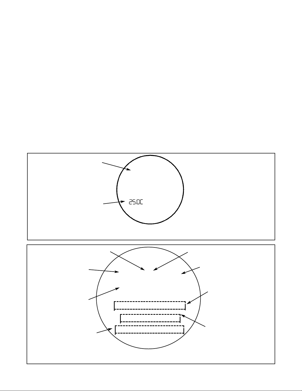
37
MODEL 5081-T SECTION 5.0
DISPLAY AND OPERATION
SECTION 5.0
DISPLAY AND OPERATION
5.1 Displays
5.2 Infrared Remote Controller (IRC) - Key Functions
5.3 Quick Start for Model 5081-T-HT
5.4 Quick Start for Model 5081-T-FF
5.5 Menu Trees
5.6 Diagnostic Messages
5.7 Default Settings
5.8 Security
5.9 Using Hold
CALIBRATE PROGRAM DIAGNOSE
/-[5ES-U1
EXIT NEXT ENTER
#"c""
mS/cm
F
A
U
L
T
H
O
L
D
Appears when transmitter
is in hold (see Section 6.3)
Appears when a disabling
condition has occurred
(see Section 7.3.2)
Active menu: CALIBRATE,
PROGRAM, or DIAGNOSE
Sub-menus, prompts, and
diagnostic messages appear
here
Conductivity value
Units of display
Available commands for submenu, prompt, or diagnostic
FIGURE 5-2. Program Display Screen
The program display screen appears when calibrating, programming, or reading diagnostic messages.
FIGURE 5-1. Process Display Screen
The process display screen appears during normal operation.
Conductivity value
Temperature in °C or °F
5.1 DISPLAYS
Figure 5-1 shows the process display screen, and Figure 5-2 shows the program display screen.
♥
Indicates HART or FOUNDATION fieldbus
digital communications
#"c""
mS/cm
Page 44

38
5.2 INFRARED REMOTE CONTROLLER (IRC) - KEY FUNCTIONS
The infrared remote controller is used to calibrate and program the transmitter and to read diagnostic messages.
See Figure 5-3 for a description of the function of the keys.
Hold the IRC within 6 feet of the transmitter, and not more than 15 degrees from horizontal to the display window.
FIGURE 5-3. Infrared Remote Controller.
RESET - Press to end the current oper-
ation and return to the process display.
Changes will NOT be saved. RESET
does not return the transmitter to factory
default settings.
CAL - Press to access the calibrate
menu.*
PROG - Press to access the program
menu.*
DIAG - Press to view diagnostic messages.*
HOLD - Press to access the prompt
that turns on or off the Hold function.
HOLD puts the transmitter in hold mode
and sets the output to a pre-programmed value. Press RESET to exit
hold mode.
Editing Keys - Use the editing keys to
change the value of a flashing display.
The left and right arrow keys move the
cursor one digit at a time across a number. The up and down arrow keys
increase or decrease the value of the
selected digit. The up and down arrow
keys also scroll the display through the
items in a list.
* Pressing CAL, PROG, or DIAG causes
the program screen to appear with the
selected menu (CALIBRATE, PROGRAM,
OR DIAGNOSE) showing. See Figure 5-2.
The first sub-menu (or the first diagnostic
message) also appears. Figure 5-4 shows
the complete menu tree.
ENTER - Press to advance from a submenu to the first prompt under the submenu. Pressing ENTER also stores the
selected item or value in memory and
advances to the next prompt.
NEXT - Press to advance to the next
sub-menu.
EXIT - Press to end the current operation. The transmitter returns to the first
prompt in the present sub-menu.
Changes will NOT be saved.
MODEL 5081-T SECTION 5.0
DISPLAY AND OPERATION
Page 45

39
MODEL 5081-T SECTION 5.0
DISPLAY AND OPERATION
5.3 QUICK START FOR MODEL 5081-T-HT (HART)
1. On the Remote, press PROG, NEXT, NEXT, ENTER.
2. Use the arrow buttons to select COnduc (conductivity), nAOH (Sodium Hydroxide 0-15%), HCL (Hydrochloric
Acid 0-16%), H2SO4L (Sulfuric Acid 0-30%), H2SO4H (Sulfuric Acid 96-99.7%), or CuSt (custom curve) mode.
Press ENTER. If you chose CuSt, continue with step 3. If you chose COnduc or one of the preprogrammed %
concentration modes, skip step 3 and go to step 4.
3. If you selected CuST, you will see the Setup Custom screen. To move to the custom curve configuration menu,
press ENTER. You will automatically return to this same Setup Custom screen after configuration is complete.
To continue transmitter display programming, press NEXT in the Setup Custom screen.
4. Use the arrow keys to toggle temperature units between Celsius and Farenheit.
5. Press ENTER then RESET.
6. Press PROG, ENTER.
7. Use the arrow buttons to enter the 4 mA value. Press ENTER.
8. Use the arrow buttons to enter the 20 mA value. Press ENTER then RESET.
9. Press PROG, NEXT, ENTER.
10. Use the arrow key to toggle t AutO to On or OFF to select using either the process temperature (tAutO = On)
or a manual temperature (tAutO = OFF). Press ENTER. If you selected t AutO = OFF, you will be prompted
to enter the manual temperature; use the arrow keys, then press ENTER.
11. If you selected CondUC in step 2, you will see a COMP (Temperature Compensation type) screen. Use the
arrow keys to select desired temperature compensation: LinEAr (linear) or nOnE (raw or uncompensated conductivity). Press ENTER. If you are in LinEAR mode, you can now enter a particular temperature slope (default
is 2%/degC), then press ENTER to apply the slope.
12. Press RESET.
13. Press CAL, NEXT, NEXT, NEXT, ENTER.
14. Use the arrow buttons to enter the cell constant of the sensor. Press ENTER, then EXIT.
15. To “zero” the sensor in air, press CAL, NEXT, ENTER.
16. Hold the sensor in air to zero. Press ENTER, then EXIT.
17. If you are measuring % concentration (nAOH, HCL, H2SO4L, or H2SO4H) or custom curve (CuSt), quick start
is complete; proceed to step 20.
18. If you are measuring conductivity (CondUC), then standardize the sensor by placing the sensor in a solution
of known conductivity value. Press CAL, ENTER.
19. Use the arrow buttons to enter the current conductivity value of the solution. Press ENTER.
20. Press RESET.
To reset transmiter to factory default settings:
1. Press PROGRAM, NEXT, NEXT, NEXT, NEXT, NEXT. The screen should say "dEFAULt". Press ENTER.
2. Use the arrow keys to toggle between nO (retain your configuration and calibration settings) and YES (restore
factory default settings to all variables).
3. Press ENTER, then EXIT.
Page 46

MODEL 5081-T SECTION 5.0
DISPLAY AND OPERATION
5.4 QUICK START FOR MODEL 5081-T-FF/FI (FOUNDATION FIELDBUS)
1. On the Remote, press PROG, NEXT, ENTER.
2. Use the arrow buttons to select COnduc (conductivity), nAOH (Sodium Hydroxide 0-15%), HCL (Hydrochloric Acid 016%), H2SO4L (Sulfuric Acid 0-30%), H2SO4H (Sulfuric Acid 95-99.99%), or CuSt (custom curve) mode. Press
ENTER. If you chose CuSt, continue with step 3. If you chose COnduc or one of the preprogrammed % concentration
modes, skip step 3 and go to step 4.
3. If you selected CuST, you will see the Setup Custom screen. To move to the custom curve configuration menu, press
ENTER. You will automatically return to this same Setup Custom screen after configuration is complete. To continue
transmitter display programming, press NEXT in the Setup Custom screen.
4. Use the arrow keys to toggle temperature units between Celsius and Farenheit.
5. Press ENTER then RESET.
6. Press PROG, ENTER.
7. Use the arrow key to toggle t AutO to On or OFF to select using either the process temperature (tAutO = On) or a
manual temperature (tAutO = OFF). Press ENTER. If you selected t AutO = OFF, you will be prompted to enter the
manual temperature; use the arrow keys, then press ENTER.
8. If you selected CondUC in step 2, you will see a COMP (Temperature Compensation type) screen. Use the arrow keys
to select desired temperature compensation: LinEAr (linear) or nOnE (raw or uncompensated conductivity). Press
ENTER. If you are in LinEAR mode, you can now enter a particular temperature slope (default is 2%/degC), then press
ENTER to apply the slope.
9. Press RESET.
10. Press CAL, NEXT, NEXT, NEXT, ENTER.
11. Use the arrow buttons to enter the cell constant of the sensor. Press ENTER, then EXIT.
12. To “zero” the sensor in air, press CAL, NEXT, ENTER.
13. Hold the sensor in air to zero. Press ENTER, then EXIT.
14. If you are measuring % concentration (nAOH, HCL, H2SO4L, or H2SO4H) or custom curve (CuSt), quick start is com-
plete; proceed to step 20.
15. If you are measuring conductivity (CondUC), then standardize the sensor by placing the sensor in a solution of known
conductivity value. Press CAL, ENTER.
16. Use the arrow buttons to enter the current conductivity value of the solution. Press ENTER.
17. Press RESET.
To reset transmiter to factory default settings:
1. Press PROGRAM, NEXT, NEXT, NEXT. The screen should say "dEFAULt". Press ENTER.
2. Use the arrow keys to toggle between nO (retain your configuration and calibration settings) and YES (restore factory
default settings to all variables).
3. Press ENTER, then EXIT.
40
Page 47
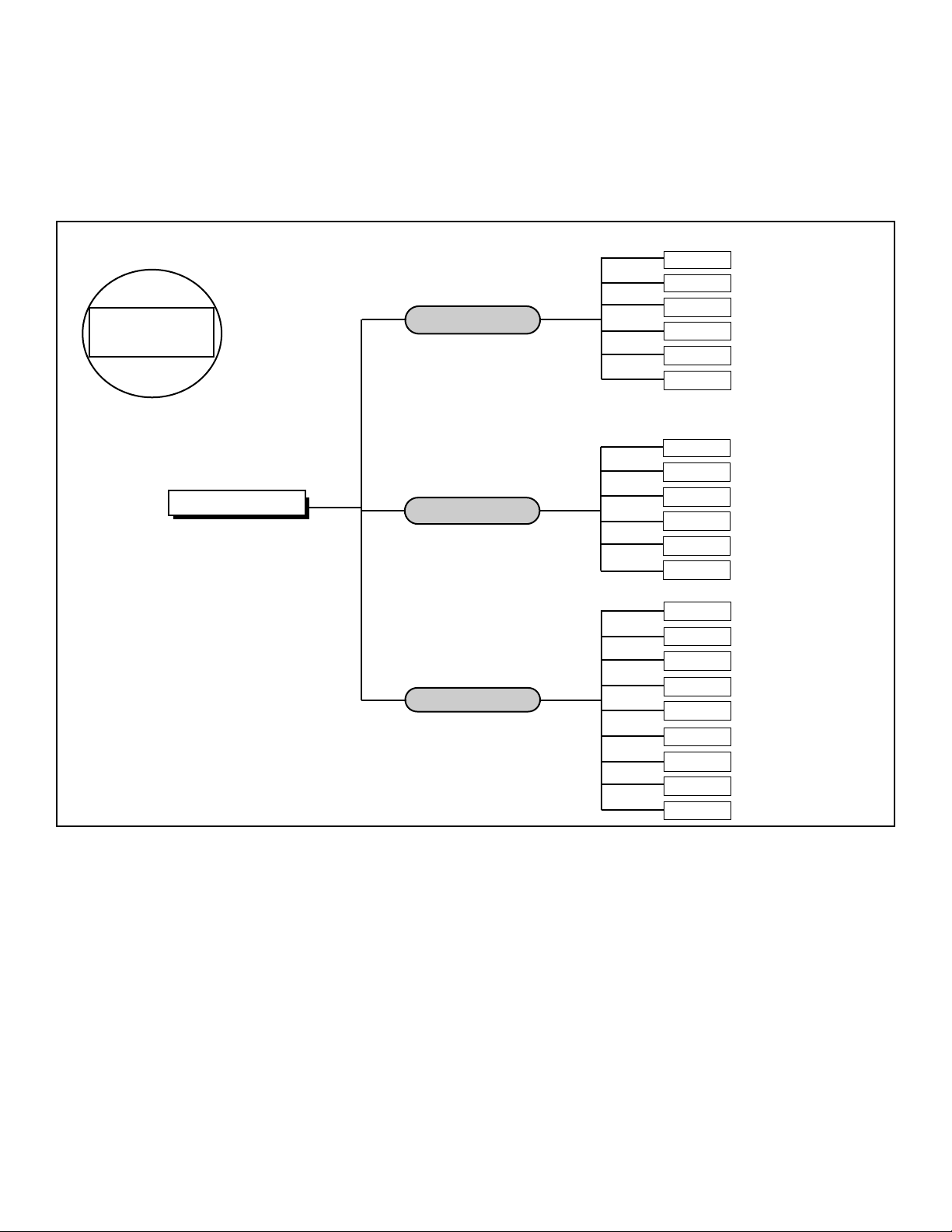
41
MODEL 5081-T SECTION 5.0
DISPLAY AND OPERATION
5.5 MENU TREE - Conductivity
The Model 5081-T transmitter has three menus: CALIBRATE, PROGRAM, and DIAGNOSE. Under the Calibrate and
Program menus are several sub-menus. Figure 5-4 shows the complete menu tree for Model 5081-T-HT. Figure 5-5
shows the complete menu tree for Model 5081-T-FF.
U1
7
:!<[9:1
-E< /!
922<U
'"*#\=\4U
/1[[!/9P<U
<Q2U
/-[!2
4-SG
U<[9:1
1
2D>[=T
'"""
25.0C 12.00mA
CAL key
PROG key
DIAG key
HOLD key
Model 5081T-HT
Process Display Screen
µS/cm
/-[5ES-U1
/1[[!/9P<U
<1P<9S!"
U1
7
:!-G6
U1
7
:
G5<:[-A
4-SU
<1U>:!/V<=
G12->[=
9VU:VU
PROGRAM
Process Display
FIGURE 5-4. Menu Tree
9>U:>U!/-[
CALIBRATION
DIAGNOSTICS
Page 48

MODEL 5081-T SECTION 5.0
DISPLAY AND OPERATION
42
PROGRAM MENU MNEMONICS
9>U:>U
Current output menu header
&
7
-
4mA current output (setpoint)
$"7-
20mA current output (setpoint)
4Q[G
Current output on hold
2->[U
Fault condition current output setting
G:P
Current output dampening time
U1<U
Current output test value
U17:
Temperature menu header
U->U9
Automatic temperature compensation
U
7
-P
Manual temperature compensation input
G5<:[-A
Display menu header
UA:
Conductivity measurement type
U1
7
:!
°C / °F toggle selection
9>U:>U!
Current (mA) or percent of full scale display
/9G1
Security code
922<U
Conductance Offset value
U17:!<[9:1
-E< /!
922<U
'"*#\=\22
/1[[!/9P<U
<Q2U
4-SG
U<[9:1
2D>[=T
'"""
25.0C 12.00mA
CAL key
PROG key
DIAG key
HOLD key
Model 5081T-FF
Process Display Screen
µS/cm
/-[5ES-U1
/1[[!/9P<U
<1P<9S!"
U17:!-G6
U1
7
:
G5<:[-A
<1U>:!/V<=
G12->[=
PROGRAM
Process Display
FIGURE 5-5. Menu Tree
CALIBRATION
DIAGNOSTICS
Page 49

43
MODEL 5081-T SECTION 5.0
DISPLAY AND OPERATION
5.6 DIAGNOSTIC MESSAGES
Whenever a warning or fault limit has been exceeded, the transmitter displays diagnostic messages to aid in troubleshooting. Diagnostic messages appear in the same area as the temperature/output readings in the process display
screen (see Figure 5-2). The display alternates between the regular display and the diagnostic message. Figure 5-4
shows the diagnostic fault messages for conductivity for Model 5081-T-HT. Figure 5-4 shows the diagnostic fault messages for conductivity for Model 5081-T-FF. If more than one warning or fault message has been generated, the messages appear alternately.
See Section 10.0, Troubleshooting, for the meanings of the fault and warning messages.
5.7 DEFAULT SETTINGS
Table 5-1 shows the diagnostic fault messages for conductivity for Model 5081-T-FF. Table 5-2 shows the diagnostic fault
messages for conductivity for Model 5081-T-HT.
VARIABLE NAME MNEMONIC FACTORY SETTINGS CUSTOMER SETTINGS
Program Menu
Temperature
UHOR
Auto temperature compensation UDVUQ on ___________
Manual temperature UODP 25.0°C (overridden by auto) ___________
Temperature compensation algorithm /97: ([LPHDS or P9P1) LInEAr ___________
Display
GLTRNDY
Measurement type UYR (/QPG>/ or P-94 or 4/[ CondUC ___________
or 4$<9&[ or 4$<9&4 or /VTU)
Temperature (°C or °F) UHOR C ___________
Output (mA or %) QVURVU Cur ___________
Security Code FQGH 000 ___________
Custom Curve
<1U>:!!/V<U
___________
Reference temperature U!SHI 25.0°C ___________
Range
Measurement range
S-PJ1 Auto ___________
Calibrate Menu
Cell constant /1[[!/QPTU 3.00 ___________
Temperature slope U17:!TN9RH 2.000 ___________
Diagnose Menu
Diagnose SAMPLE READINGS
(Each segment displays the current value in the transmitter.)
Absolute conductivity -ET 1000 µS ___________
Off Set 9II<U 0.0 µS ___________
Cell constant /1[[!/9P<U 3.00/cm ___________
Temperature slope UTNQRH 2.000 ___________
Software version TQIU A02.09 ___________
Hardware version 4-SG 01 ___________
Show fault warnings 2D>[=< none ___________
TABLE 5-1. Default Settings for Model 5081-T-FF/FI
Page 50

44
MODEL 5081-T SECTION 5.0
DISPLAY AND OPERATION
VARIABLE NAME MNEMONIC FACTORY SETTINGS CUSTOMER SETTINGS
Program Menu
Output
9VURVU
– ___________
4 mA &!O- 0 µS ___________
20 mA $"!O- 20 mS ___________
Hold KQNG 21 mA ___________
Fault IDVNU 22 mA ___________
Dampening GRP 0 samples/second ___________
Test UHTU 04.00 mA ___________
Temperature
UHOR
Auto temperature compensation UDVUQ on ___________
Manual temperature UODP 25.0°C (overridden by auto) ___________
Temperature compensation algorithm /97: ([LPHDS or P9P1) LInEAr ___________
Display
GLTRNDY
Measurement type UYR (/QPG>/ or P-94 or 4/[ CondUC ___________
or 4$<9&[ or 4$<9&4 or /VTU)
Temperature (°C or °F) UHOR C ___________
Output (mA or %) QVURVU Cur ___________
Security Code FQGH 000 ___________
Custom Curve
<1U>:!!/V<
U
___________
Reference temperature U!SHI 25.0°C ___________
Range
Measurement range
S-PJ1 Auto ___________
Calibrate Menu
Cell constant /1[[!/QPTU 3.00 ___________
Temperature slope U17:!TN9RH 2.000 ___________
Output Calibration 9>U:>U!/-[ ___________
Diagnose Menu
Diagnose SAMPLE READINGS
(Each segment displays the current value in the transmitter.)
Absolute conductivity -ET 1000 µS ___________
Off Set 9II<U 0.0 µS ___________
Cell constant /1[[!/9P<U 3.00/cm ___________
Temperature slope UTNQRH 2.000 ___________
Software version TQIU A02.09 ___________
Hardware version 4-SG 01 ___________
Show fault warnings 2D>[=< none ___________
TABLE 5-2. Default Settings for Model 5081-T-HT
Page 51

45
5.8 SECURITY
5.8.1 General. Use the programmable security code to protect program and calibration
settings from accidentally being changed. The transmitter is shipped with the security feature disabled.
5.8.2 Entering the Security Code.
1. If calibration and program settings are protected with a security code, pressing PROG
or CAL on the infrared remote controller causes the Id screen to appear.
2. Use the editing keys to enter the security code. Press ENTER .
3. If the security code is correct, the first sub-menu appears. If the security code is incorrect, the process display reappears.
5.8.3 Retrieving a Lost Security Code.
1. If the security code has been forgotten, enter 555 at the Id prompt and press ENTER .
The transmitter will display the present code.
2. Press EXIT to return to the process display.
3. Press PROG or CAL . The Id screen appears.
4. Use the editing keys to enter the security code just shown; then press ENTER .
5. The first sub-menu under the selected menu will appear.
MODEL 5081-T SECTION 5.0
DISPLAY AND OPERATION
PROGRAM
5G
EXIT ENTER
"""
5.9 USING HOLD
During calibration, the sensor may be exposed to solutions having concentration outside the normal range of the process.
To prevent false alarms and undesired operation of chemical dosing pumps, place the transmitter in hold during calibration. Activating hold keeps the transmitter output at the last value or sends the output to a previously determined value.
See Section 7.2, Output Ranging, for details.
After calibration, reinstall the sensor in the process stream. Wait until readings have stabilized before deactivating Hold.
To activate or deactivate Hold:
1. Press HOLD on the remote controller.
2. The HoLd prompt appears in the display. Press or to toggle Hold between On and OFF.
3. Press ENTER to save.
Page 52

46
MODEL 5081-T SECTION 6.0
START-UP AND CALIBRATION
SECTION 6.0
START-UP AND CALIBRATION
6.1 ACCESSING THE CALIBRATE MENU
The “Calibrate” menu is used to calibrate the transmitter to known temperature and conductivity values. This menu also contains the temperature calibration operation to establish the temperature slope.
Figure 6-1 illustrates the relationship between the Calibrate Menu and its sub-menus. Each sub-menu leads to a series of
prompts that are used for calibration.
U1
7
:!<[9:1
-E< /!
922<U
'"*#\=\4U
/1[[!/9P<U
<Q2U
/-[!2
4-SG
U<[9:1
1
2D>[=T
'"""
25.0C 12.00mA
CAL key
PROG key
DIAG key
HOLD key
Model 5081T-HT
Process Display Screen
µS/cm
/-[5ES-U1
/1[[!/9P<U
<1P<9S!"
U17:!-G6
U1
7
:
G5<:[-A
4-SU
<1U>:!/V<=
G12->[=
9VU:VU
PROGRAM
Process Display
FIGURE 6-1. Menu Tree
9>U:>U!/-[
CALIBRATION
DIAGNOSTICS
Page 53

47
6.2 CALIBRATE MENU
To access the “Calibrate” menu, press the CAL
key on the Infrared Remote Control. If security has
been enabled, the secondary process display will
be replaced with a prompt asking for the “Id”.
Using the IRC editing keys, enter the “Id”. If the
correct “Id” is entered, the CALibrAtE sub-menu
will appear when ENTER is pressed.
If the CALibrAtE sub-menu does not appear when
ENTER is pressed, see Section 5.8.3 (step 8) for
procedure to find correct code.
6.2.1 Calibrate
1. With the sensor in a standard solution of known
conductivity value, allow the temperature of the
sensor to stabilize (10 min).
2. To access the CALIbrAtE menu, press the CAL
button on the IRC.
3. Press ENTER to access the CAL segment with flashing prompt.
4. Use the IRC editing keys to indicate the conductivity values of the standard solution on the screen.
5. Press ENTER then EXIT to enter the standard solution value and return to the main screen.
6.2.2 Sensor 0
From the main screen, press CAL, then press NEXT to enter the SEnSOr 0 menu. Press ENTER to access the SEnSOr
0 sub-menu. With the sensor attached and in air, press ENTER again to zero the sensor. Press EXIT to return to the
SEnSOr 0 sub-menu.
6.2.3 Temp Adj
1. Press NEXT and then ENTER to access the tEMP sub-menu with flashing prompt. With the sensor in any solution of
known temperature, allow the temperature of the sensor to stabilize (10 min.). Use the editing keys of the IRC to change
the displayed value as needed.
2. Press ENTER to standardize the temperature reading and return to the tEMP AdJ screen.
6.2.4 Cell Constant
1. When the CALibrAtE sub-menu has been accessed, press NEXT four (4) times and then ENTER to access the CELL
COnSt menu segment with the flashing cell constant prompt.
2. Using the arrow keys on the IRC, enter your sensor’s cell constant as indicated on the sensor’s tag or specification
sheet.
3. Press ENTER to save the cell constant into the transmitter memory and return to the CELL COnSt sub-menu.
MODEL 5081-T SECTION 6.0
START-UP AND CALIBRATION
Model 5081-T-HT Model 5081-T-FF
//--[[55EESS--UU11 //--[[55EESS--UU11
<<11PP<<QQSS!!"" <<11PP<<QQSS!!""
UU1177::!!--GGMM UU1177::!!--GGMM
//11[[[[!!//99PP<<UU
//11[[[[!!//99PP<<UU
UU1177::!!<<[[QQ::11
UU1177::!!<<[[QQ::11
99VVUU::VVUU!!//--[[
Page 54
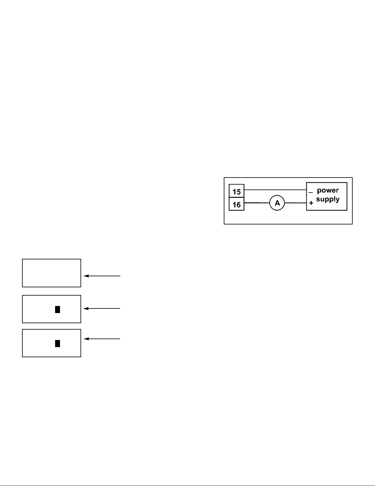
48
MODEL 5081-T SECTION 6.0
START-UP AND CALIBRATION
6.2.5 Temp Slope
1. Press NEXT to enter the tEMP SLOPE menu.
The correct temperature slope must be entered into the transmitter to ensure an acceptable process variable measurement under fluctuating process temperature conditions. Enter the slope in measured conductivity units per degree temperature change using the IRC’s arrow keys. Press ENTER to enter the slope into memory; then press EXIT to return
to the main screen.
2. If the temperature slope of the process is not known but you wish to approximate it, refer to the following guide and press
ENTER to proceed on to tEMP SLOPE sub-menu with flashing prompt. Utilize the IRC editing keys to generate the
desired slope value. Press ENTER then EXIT to return to the main screen.
Acids: 1.0 to 1.6% per °C
Bases: 1.8 to 2.2% per °C
Salts: 2.2 to 3.0% per °C
Water: 2.0% per °C
6.2.6 Output Cal
Although the transmitter outputs are calibrated at the factory, they can
be trimmed in the field to match the reading from a standard current
meter. Both the 4 mA and the 20 mA outputs can be trimmed. During
output calibration the transmitter is in Hold. The output current will go
to the value programmed in Section 7.2.
PROCEDURE
1. Wire an accurate milliammeter as shown in Figure 6-2.
2. Press CAL on the remote controller.
3. Press NEXT until the OUtPUt CAL submenu appears. Press ENTER.
4. Use the arrow keys to change the display to match the reading from the milliammeter. Press ENTER.
5. Use the arrow keys to change the display to match the reading from the milliammeter. Press ENTER. Press RESET to return to the main display.
CALIBRATE
9>UR>U!!/-[
EXIT NEXT ENTER
CALIBRATE
/VS
EXIT NEXT ENTER
$"c""
CALIBRATE
/VS
EXIT NEXT ENTER
&c"""
FIGURE 6-2. Current Output Calibration
Page 55

49
MODEL 5081-T SECTION 6.0
START-UP AND CALIBRATION
TABLE 6-1. CALIBRATE MENU MNEMONICS
/-[5ES-U1 Calibrate menu header
/-[ Sensor calibration
U17:!<[9:1 Sub-menu header
-GM!<[9:1 Sub-menu header
U<[9:1 Slope adjustment %/°C
/1[[!/9P<U Sub-menu header
<1P<9S! Sub-menu header
<1P<9S!" Sensor "0" (performed in air)
U17:!-G6 Sub-menu header
U17: Temperature adjustment °C/°F
Page 56

50
MODEL 5081-T SECTION 7.0
PROGRAMMING
SECTION 7.0
PROGRAMING
7.1 General
7.2 Output
7.3 Temp
7.4 Display
7.5 HART
7.6 Setup Cust
7.7 Range
7.8 Default
7.1 GENERAL
This section describes how to do the following:
1. assign values to the 4 and 20 mA outputs (for 5081-T-HT only)
2. set the current generated by the transmitter during hold (for 5081-T-HT only)
3. set the current generated by the transmitter when a fault is detected (for 5081-T-HT only)
4. enable and disable automatic temperature correction
5. program the type measurement
6. program HART digital communications
7. set measurement range to automatic (default) or specific conductance ranges
8. reset all settings to factory default condition
Model 5081-T-HT Model 5081-T-FF
99VVUU::VVUU UU1177::
UU1177:: 00LL<<::[[--AA
00LL<<::[[--AA <<11UUVV::!!//VV<<UU
44--;;==
001122--VV[[UU
<<11UUVV::!!//VV<<UU
SS--PPJJ11
001122--VV[[UU
SS--PPJJ11
Page 57

MODEL 5081-T SECTION 7.0
PROGRAMMING
7.2 OUTPUT (5081-HT only)
7.2.1 Purpose
This section describes how to do the following:
1. assign values to the 4 and 20 mA outputs
2. set the output current generated during hold
3. set the output current generated when a fault is detected
4. control the amount of dampening on the output signal
5. generate a test current.
7.2.2 Definitions
1. CURRENT OUTPUTS. The transmitter provides a continuous 4 - 20 mA output directly proportional to the conductivity or resistivity.
2. HOLD. During calibration and maintenance the transmitter output may be outside the normal operating range. Placing
the transmitter on hold prevents false alarms or the unwanted operation of chemical dosing pumps. The transmitter
output can be programmed to remain at the last value or to generate any current between 3.80 and 22.00 mA. During
hold, the transmitter displays the present concentration and temperature. The word HOLD appears in the display.
3. FAULT. A fault is a system disabling condition. When the transmitter detects a fault, the following happens:
a. The display flashes.
b. The words FAULT and HOLD appear in the main display.
c. A fault or diagnostic message appears in the display.
d. The output signal remains at the present value or goes to the programmed fault value. Permitted values
are between 3.80 and 22.00 mA.
e. If the transmitter is in HOLD when the fault occurs, the output remains at the programmed hold value. To alert the
user that a fault exists, the word FAULT appears in the main display, and the display flashes. A fault or diagnostic
message also appears.
f. If the transmitter is simulating an output current when the fault occurs, the transmitter continues to generate the sim-
ulated current. To alert the user that a fault exists, the word FAULT appears in the display, and the display flashes.
4. DAMPEN. Output dampening smooths out noisy readings. But it also increases the response time of the output. To
estimate the time (in minutes) required for the output to reach 95% of the final reading following a step change, divide
the setting by 20. Thus, a setting of 140 means that, following a step change, the output takes about seven minutes
to reach 95% of final reading. The output dampen setting does not affect the response time of the process display. The
maximum setting is 255.
5. TEST. The transmitter can be programmed to generate a test current.
51
Page 58
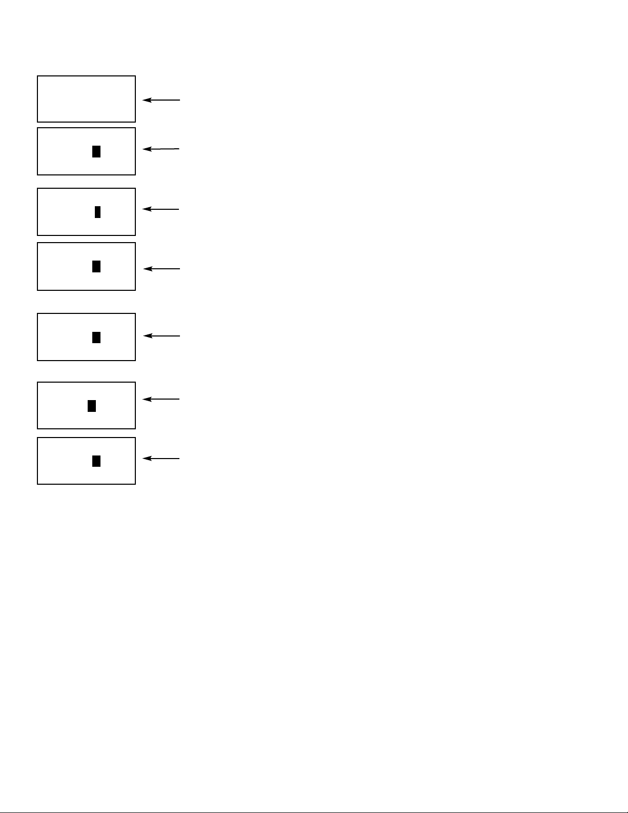
52
MODEL 5081-T SECTION 7.0
PROGRAMMING
7.2.3 Procedure
1. Press PROG on the remote controller. The OutPut submenu appears.
2. Press ENTER. The screen displays the 4 MA prompt. Use the arrow keys to change
the setting. Press ENTER to save.
3. The screen displays the 20 MA prompt. Use the arrow keys to change the setting.
Press ENTER to save.
4. The screen displays the HoLd prompt. Use the arrow keys to change the setting to
the output desired when the transmitter is in hold. The range is 3.80 to 22.00 mA.
Entering 00.00 causes the transmitter to hold the output at the value it was when
placed in hold. The hold setting overrides the fault setting. Press ENTER to save.
5. The screen displays the FAULt prompt. Use the arrow keys to change the setting to
the output desired when the transmitter detects a fault. The range is 3.80 to 22.00 mA.
Entering 00.00 causes the transmitter to hold the output at the value it was when the
fault occurred. Press ENTER to save.
6. The screen displays the dPn prompt. Use the arrow keys to change the setting. The
range is 0 to 255. Press ENTER to save.
7. The screen displays the tESt prompt. Use the arrow keys to enter the desired test current. Press ENTER to start the test. Press EXIT to end the test.
8. Press RESET to return to the process display.
PROGRAM
4Q[G
EXIT ENTER
$#c""
PROGRAM
2->[U
EXIT ENTER
$$c""
PROGRAM
G:P
EXIT ENTER
PROGRAM
9VU:VU
EXIT NEXT ENTER
PROGRAM
&7-
EXIT ENTER
""c""
PROGRAM
$"7-
EXIT ENTER
#"c""
PROGRAM
UHTU
EXIT ENTER
# $c""
"""
Page 59
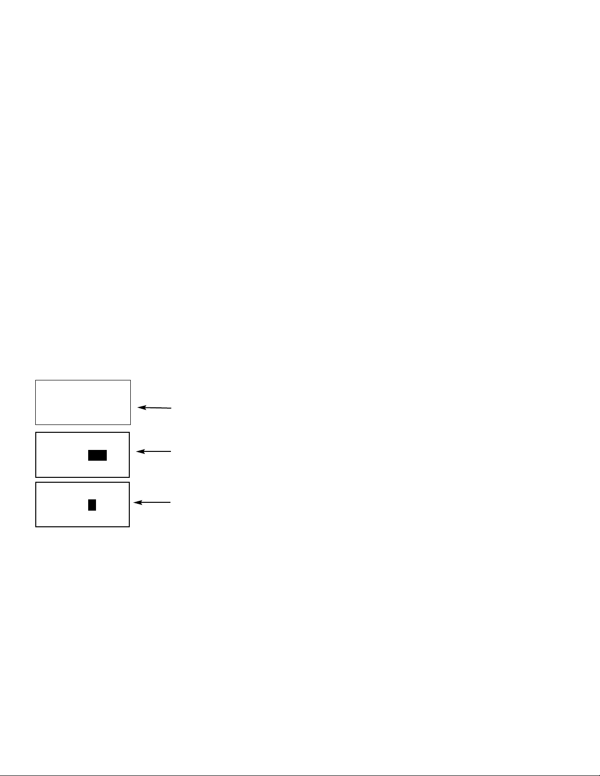
MODEL 5081-T SECTION 7.0
PROGRAMMING
7.3 TEMP
7.3.1 Purpose
This section describes how to do the following:
1. Enable and disable automatic temperature compensation
2. Set a manual temperature compensation value for conductivity measurements
3. Tell the transmitter the type of temperature element in the sensor
7.3.2 Definitions
1. AUTOMATIC TEMPERATURE COMPENSATION. Conductivity measurements are directly affected by temperature. A
correction equation in the software automatically corrects for changes caused by temperature. In automatic temperature correction, the transmitter uses the temperature measured by the sensor for all calculations in which temperature
is used.
2. MANUAL TEMPERATURE COMPENSATION. In manual temperature compensation, the transmitter uses the temperature entered by the user as the reference temperature for corrections of conductivity readings. It does not use the
actual process temperature.
CAUTION
Changing the reference temperature from the default 25°C (77°F) can have large
effects on the conductivity readings and will require different temperature slopes.
7.3.3 Procedure
1. Press PROG on the remote controller.
2. Press NEXT until the tEMP submenu appears. Press ENTER.
3. The screen displays the tAUtO (automatic temperature compensation) prompt.
Press or to toggle between On and OFF. Press ENTER to save.
4. If you disable tAuto, the tMAN prompt appears. Use the arrow keys to change the
temperature to the desired value. To enter a negative number, press
or
until no
digit is flashing. Then press or to display the negative sign. The temperature
entered in this step will be used in all measurements, no matter what the
process temperature is. Press ENTER to save.
5. Press RESET to return to the process display.
PROGRAM
U->U9
EXIT ENTER
98
PROGRAM
U7-P
EXIT ENTER
"$'c"
PROGRAM
U17:
EXIT NEXT ENTER
53
Page 60
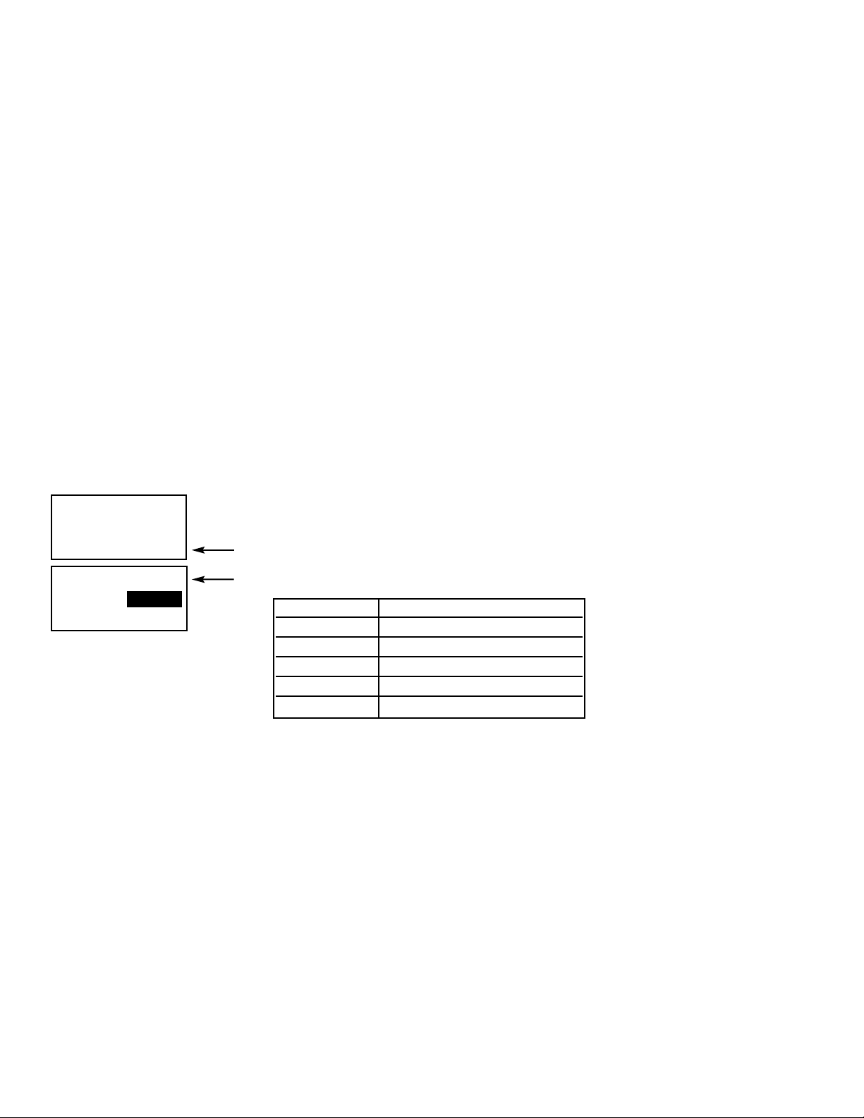
54
MODEL 5081-T SECTION 7.0
PROGRAMMING
1. Press PROG on the remote controller.
2. Press NEXT until the diSPLAy submenu appears. Press ENTER.
3. Press or to display the desired measurement. Press ENTER to save.
4. tEMP will appear. Press or to display the desired temperature reading, C or F.
Press ENTER.
5. OUtPUt will appear. Press or to display the desired 4-20 output value, Cur or %.
Press ENTER.
6. COdE will appear. Using the arrow keys on the remote control, enter the desired 3-digit
security code for accessing the Calibration, Program, and Diagnostic functions via the
Remote Control handheld. Press ENTER. The dISPLAY mnemonic will appear.
PROGRAM
UA:1
EXIT ENTER
/QPGVF
PROGRAM
G5<:[-A
EXIT NEXT ENTER
7.4 DISPLAY
7.4.1 Purpose
This section describes how to do the following:
1. Configure the transmitter to measure conductivity, resistivity, or set up a custom curve
2. Set the temperature units to °C or °F
3. Set the output to current or percent of full scale
4. Enter a security code.
7.4.2 Definitions
1. MEASUREMENT. The transmitter can be configured to measure conductivity in mS/cm or resistivity in MegOhms, or
configured with a 3-5 point custom curve for special applications.
2. OUTPUT CURRENT. The transmitter generates a 4-20 mA output signal directly proportional to the conductivity or resistivity of the sample. The output signal can be displayed as current (in mA) or as percent of full scale.
5. SECURITY CODE. The security code unlocks the transmitter and allows access to all menus.
7.4.3 Procedure
COnduc Conductivity
nAOH Sodium Hydroxide 0-15%
HCL Hydrochloric Acid 0-16%
H2SO4L Sulfuric Acid 0-30%
H2SO4H Sulfuric Acid 96-99.7%
CuSt Custom Curve
Page 61

7.5 HART
In multi-drop operation, polling addresses can be more conveniently set and debugging more conveniently performed
using the infrared remote controller.
PROGRAM
4-SU
EXIT NEXT ENTER
1. Press PROG on the infrared remote controller.
2. Press NEXT until the screen at left appears. Press ENTER.
3. The HART menu tree is shown at left. Use the arrow keys to change settings.
Press ENTER to store. Press NEXT to move to the next item on the menu.
--GGGGSSHHTTTT """"
EXIT NEXT ENTER
::SSHH--77EE ""''
EXIT NEXT ENTER
EEVVSS<<UU 99IIII
EXIT NEXT ENTER
55GG """"""""""""""
EXIT NEXT ENTER
MODEL 5081-T SECTION 7.0
PROGRAMMING
55
Page 62
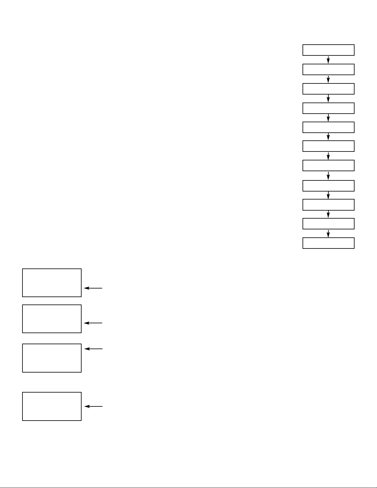
56
7.6 SETUP CUST
The Model 5081-T contains a curve fitting program that can create a second order curve for
3 to 5 user supplied data points. If only two points are entered, a straight line will be used.
These points are from numerical data previously collected that is entered via the keypad. All
data point must be approximately the same reference temperature.
Best results will be obtained by selecting data points that are representative of the typical
operating range and are at least 5% different conductivity values. Plotting the graph of conductivity vs. concentration for the data points of interest before using this procedure is highly
recommended. This will insure that unsuitable points (i.e. two concentrations with the same
conductivity) and critical points (that best describe the curve) can be determined. All data
points should be either on the rising side of the conductivity versus concentration curve or the
falling side, but not both (i.e. both side of the conductivity maximum or minimum). Following
these guideline will simplify the data entry procedure and provide optimum results.
The first point entered "COnd 1"should be at the normal operating condition. Other points,
both above and below "COnd 1" can then be entered. Very nonlinear conductivity curves may
need additional points to characterize these regions. Do not use the same data for more than
one point and only use real data - do not interpolate.
NOTE
The default values for the custom curve are three data points, reference temperature of 25°C and a linear temperature slope of 2%/°C. This combination will yield
the best results in most applications. If normal operation is over 40°C or under
10°C, the reference temperature should be changed to the normal process temperature. If the temperature slope at the reference temperature is known, it can be
used.
7.6.1 Procedure
MODEL 5081-T SECTION 7.0
PROGRAMMING
1. From the main menu, press PROG; then press NEXT four times. SetUP CuSt will
appear.
2. Press ENTER. t rEF will appear. If needed, change the reference temperature from
the factory default 25°C (77°F) to a different reference temperature for the process.
Press ENTER.
3. UnIt will appear. Press or to select the desired measurement units: µS (microSiemens), nS (milliSiemens), none (no units displayed), % (percent), or ppn (parts per
million); then press ENTER.
4. NUM PtS will appear. Press or to select the desired number of data points for a
custom conductivity curve. Selecting 2 will generate a linear relationship for conductivity and concentration at the given reference temperature.
a. Enter the concentration for Pt. 1 (displayed as µS 1). Press ENTER.
b. Enter the known conductivity for Pt. 1 in µS/cm. Press ENTER.
c. Complete this process for additional known data points. Press ENTER.
5. CALC Cust will appear. Press ENTER. PrOCESSinG will appear briefly; then APPLY
CUSt will appear. Press ENTER to enter the custom curve into memory and return to
the SetUP CuSt screen.
The Custom curve will now be used to display and output all conductivity (or resistivity)
measurements if Cust is selected in the Display menu for measurement type.
PROGRAM
U!!SHI
EXIT NEXT ENTER
PROGRAM
>P5U
EXIT NEXT ENTER
PROGRAM
8VO!!:UT
EXIT NEXT ENTER
PROGRAM
/DNF!!/VTU
EXIT NEXT ENTER
U!!SHI!!!!$'c"
>PLUTµµµ<
PVO!!RUT!!!!%
µ
µµ<!!#
/QPG!!#!!!!"c"""
µ
µµ<!!$!!!!"c"""
/QPG!!$!!!!"c"""
µ
µµ<!!%!!!!"c"""
/QPG!!%!!!!"c"""
/DNF!!/QPG
-RRNY!!/VTU
Page 63
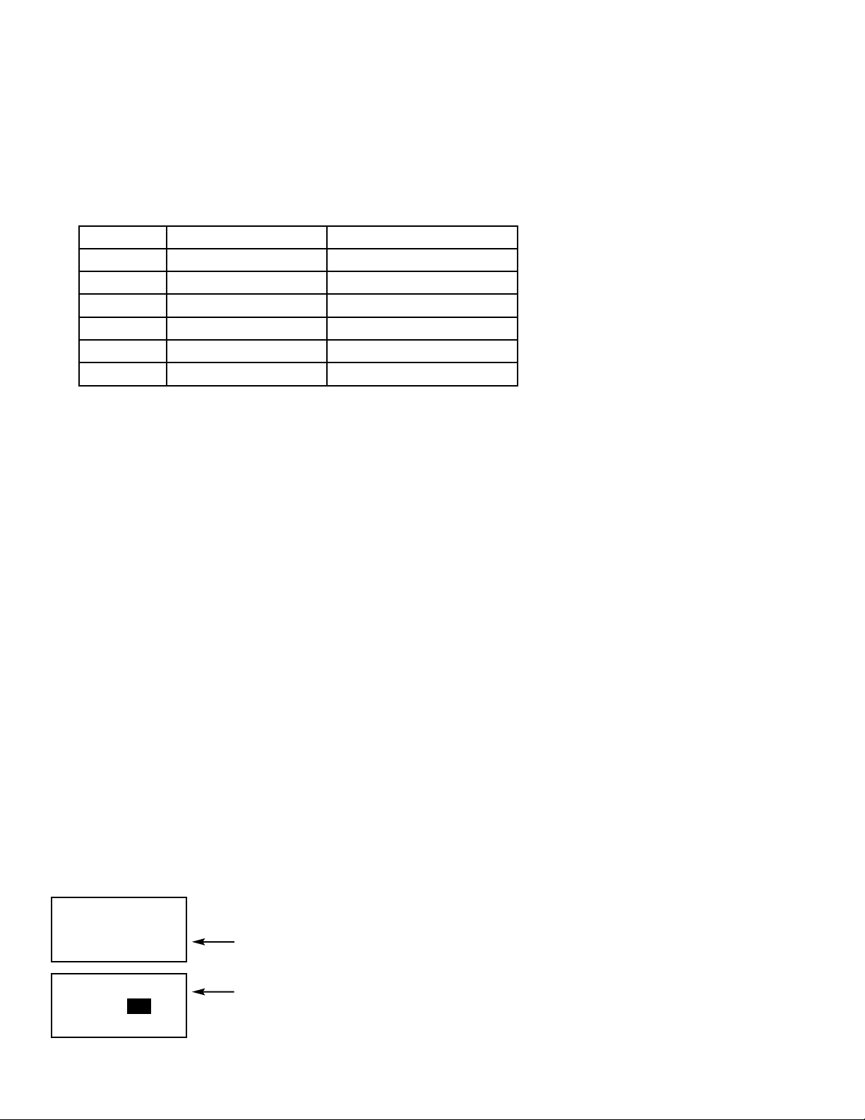
MODEL 5081-T SECTION 7.0
PROGRAMMING
7.7 RANGE
7.7.1 Purpose
This section provides the steps to select automatic ranging or a specific fixed range of measurement. Five specific conductance ranges are selectable. Setting the Model 5081 to a fixed range reduces response time.
The following conductance ranges are available:
NOTE: The selection between automatic ranging or a specified fixed range of measurement range can ONLY be done
using the IRC/Infrared Remote Controller. This selection cannot be done via HART or F
OUNDATION Fieldbus hosts or
configurators.
7.7.2 Procedure
1. Press PROG.
2. Press NEXT five times.
S-PJU!
!
(range) will appear.
3. Press ENTER. The default setting Auto will appear. This indicates that Model 5081 is in auto ranging mode.
4. To set a fixed conductance range, press the down arrow key until the desired measurement range appears.
1400mS, 550mS, 200mS, 33mS and 3mS will appear when pressing the down arrow successively.
5. When the desired range is reached, press ENTER. This disables auto ranging and limits the measurement to the
selected range.
6. Press NEXT to move to the next Programming menu item.
Setting Measurement Range Over Range Warning Limit
Auto 0uS to 1400mS None
1400mS 550mS to 1400mS None
550mS 200mS to 550mS 570mS
200mS 33mS to 200mS 207mS
33mS 3000uS to 33mS 34mS
3mS 0uS to 3000uS 3400uS
1. Press PROG on the remote controller.
2. Press NEXT until the dEFAULt appears in the display. Press ENTER.
3. Use or to toggle between nO and yES. With yES showing, press ENTER to return
to factory default settings.
PROGRAM
2-FUQSA
EXIT ENTER
P9
PROGRAM
G12->[U
EXIT NEXT ENTER
7.8 DEFAULT
7.8.1 Purpose
This section describes how to erase ALL user-defined configuration settings and return the transmitter to factory default
settings. All custom curve values and settings will be deleted.
7.8.2 Procedure
57
Page 64

58
MODEL 5081-T SECTION 8.0
FOUNDATION FIELDBUS OPERATION
SECTION 8.0
FOUNDATION FIELDBUS OPERATION
This section covers basic transmitter operation and software functionality. For detailed descriptions of the function blocks
common to all Fieldbus devices, refer to Fisher-Rosemount Fieldbus FOUNDATION Function Blocks manual, publication
number 00809-001-4783.
Figure 8-1 illustrates how the pH/ORP signal is channelled through the transmitter to the control room and the
FOUNDATION
Fieldbus configuration device.
FIGURE 8-1. Functional Block Diagram for the Model 5081-T-FF Conductivity Transmitter
with FOUNDATION Fieldbus.
SENSOR
Function Blocks
• AI1
• AI2
• Al3
• PID
• sensor type
• engineering units
• reranging
• damping
• temperature compensation
• calibration
• diagnostics
Software Functionality. The Model 5081-T software is
designed to permit remote testing and configuration of the
transmitter using the Fisher-Rosemount DeltaV Fieldbus
Configuration Tool, or other FOUNDATION fieldbus compliant host.
Transducer Block. The transducer block contains the actual measurement data. It includes information about sensor
type, engineering units, reranging, damping, temperature
compensation, calibration, and diagnostics.
Resource Block. The resource Block contains physical
device information, including available memory, manufacturer identification, type of device, and features.
FOUNDATION fieldbus Function Blocks. The Model
5081-T includes three Analog Input (AI) function blocks and
one PID function block as part of its standard offering.
Analog Input. The Analog Input (AI) block processes
the measurement and makes it available to other function blocks. It also allows filtering, alarming, and engineering unit change.
PID. The PID function block combines all of the necessary logic to perform proportional/integral/derivative
(PID) control. The block supports mode control, signal
scaling and limiting, feedforward control, override
tracking, alarm limit detection, and signal status propagation.
Page 65

MODEL 5081-T SECTION 9.0
OPERATION WITH MODEL 375
SECTION 9.0
OPERATION WITH MODEL 375
9.1 Note on Model 375 or 275 Communicator
The Model 375 or 275 Communicator is a product of Emerson Process Management, Rosemount Inc. This section
contains selected information on using the Model 375 or 275 with the Rosemount Analytical Model 5081-T-HT
Transmitter. For complete information on the Model 375 or 275 Communicator, see the Model 375 or 275 instruction manual. For technical support on the Model 375 or 275 Communicator, call Emerson Process Management at
(800) 999-9307 within the United States. Support is available worldwide on the internet at http://rosemount.com.
Note: Model 275 Communicator does not support F
OUNDATION
Fieldbus on Model 5081-T-FF.
9.2 Connecting the Communicator
Figure 9-1 shows how the Model 275 or 375 Communicator connects to
the output lines from the Model 5081-T-HT Transmitter.
CAUTION
For intrinsically safe CSA and FM
wiring connections, see the Model
375 instruction manual.
FIGURE 9-1. Connecting the HART Communicator
4-20 mA + Digital
250
ohm
Control System
Computer
Model 5081-T
Conductivity
Transmitter
Bridge
Model 375
or 275
Communicator
(“Configurator”)
59
Page 66

60
9.3 Operation
9.3.1 Off-line and On-line Operation
The Model 375 Communicator features off-line and on-line communications. On-line means the communicator is
connected to the transmitter in the usual fashion. While the communicator is on line, the operator can view measurement data, change program settings, and read diagnostic messages. Off-line means the communicator is not
connected to the transmitter. When the communicator is off line, the operator can still program settings into the
communicator. Later, after the communicator has been connected to a transmitter, the operator can transfer the
programmed settings to the transmitter. Off-line operation permits settings common to several transmitters to be
easily stored in all of them.
9.3.2 Making HART related settings from the keypad
9.3.3 Menu Tree
The menu tree for the Model 375 HART communicator is on the following page. The menu tree for the Model 375
F
OUNDATION Fieldbus communicator immediately follows.
Note: Model 375 Communicator fully supports FOUNDATION Fieldbus on Model 5081-T-FF.
1. Press MENU. The main menu screen appears. Choose Program.
2. Choose >>.
3. Choose HART.
4. To display the device ID, choose DevID. To change the polling address,
choose PollAddrs. To make burst mode settings, choose Burst. To
change the preamble count, choose Preamble.
MODEL 5081-T SECTION 9.0
OPERATION WITH MODEL 375
Calibrate Hold
PPrrooggrraamm
Display
Output Temp
Measurement
>>>>
Security
HHAARRTT
>>
DDeevvIIDD
PollAddrs
Burst Preamble
Page 67

MODEL 5081-T SECTION 9.0
OPERATION WITH MODEL 375
--------------------------------------------------------------------------------
5081-C/T 275, 375 Menu Tree for HART communications
--------------------------------------------------------------------------------
Device setup
Process variables
Cond *
Raw
Conductance
Te mp
Temp res
View status
Diag/Service
Test device
Loop test
View status
Master reset
Fault history
Hold mode
Calibration
Calibrate sensor
Zero in air
Zero in solution **
Adjust temperature
Calibrate input
Cell constant
Temp slope
D/A trim
Diagnostic vars
Cond *
Temp
Cell constant
Zero offset
Soln offset **
Temp slope ***
Input cal factor
Basic setup
Ta g
PV range values
PV LRV
PV URV
PV
PV % rnge
FIGURE 9-2. 5081-C/T-HT HART/Model 375 Menu Tree (1 of 4)
61
Page 68

62
MODEL 5081-T SECTION 9.0
OPERATION WITH MODEL 375
Basic setup (continued)
Device information
Distributor
Model
Dev id
Ta g
Date
Physicl signl code
Write protect
Snsr text
Descriptor
Message
Revision #'s
Universal rev
Fld dev rev
Software rev
Hardware rev
Detailed setup
Sensors
Main sensor
PV Type [Conductivity, Resistivity, 0-12% NaOH, 0-15% HCl, 0-25% H2SO4, 96-99.7% H2SO4,
Custom]
PV Snsr unit [uS/cm, mS/cm, mS/m, Mohm-cm, %, ppm, _]
Cond unit [uS/cm, mS/cm, mS/m] ****
Define curve ****
View custom points ****
Cell constant
Temp comp type [Linear, Neutral salt, Cation, None/Off] *..
Temp slope
Ref temp ***, ****, *.
PV sensor type
Sensor information
LSL
USL
Min span
Temperature
ATC [On, Off]
Man temp
Temp unit [ºC, ºF]
Temp snsr [RTD PT100, RTD PT1000]
Diag override (continued)
Offset error [ON, OFF]
Zero warning [ON, OFF]
Overrange [ON, OFF]
Sensor fail [ON, OFF]
FIGURE 9-2. 5081-C/T-HT HART/Model 375 Menu Tree (2 of 4)
Page 69

MODEL 5081-T SECTION 9.0
OPERATION WITH MODEL 375
Diag override (continued)
RTD fail [ON, OFF]
Sense line open [ON, OFF]
Temp high/low [ON, OFF]
Signal condition
LRV
URV
AO Damp
% rnge
Xfer fnctn
AO1 lo end point
AO1 hi end pt
Output condition
Analog output
AO1
AO Alrm typ
Fixed
Fault
Loop test
D/A trim
HART output
PV is Cond
SV is Temp
TV is Raw
Poll addr
Burst option [PV, %range/current, Process vars/crnt]
Burst mode [Off, On]
Num req preams
Num resp preams
Device information
Distributor
Model
Dev id
Ta g
Date
Write protect
Snsr text
Descriptor
Message
Revision #'s
Universal rev
Fld dev rev
Software rev
Hardware rev
FIGURE 9-2. 5081-C/T-HT HART/Model 375 Menu Tree (3 of 4)
63
Page 70

64
MODEL 5081-T SECTION 9.0
OPERATION WITH MODEL 375
Local Display
AO LOI units [mA, %]
Xmtr ID
Load Default Conf.
Review
PV
PV AO
PV LRV
PV URV
--------------------------------------------------------------------------------
Notes:
* Can be Cond, Res, NaOH, HCl, H2SO4, or Custom
** Valid only when PV Type = NaOH, HCl, 0-25% H2SO4, or Custom
*** Valid only when Temp comp type = Linear
**** Valid only when PV Type = Custom
*. Valid only when PV Sensor Type = Toroidal
*.. Valid only when PV Type = Conductivity or Resistivity
FIGURE 9-2. 5081-C/T-HT HART/Model 375 Menu Tree (4 of 4)
Page 71

MODEL 5081-T SECTION 9.0
OPERATION WITH MODEL 375
5081-C/T-FF/FI 375 Menu Tree
-----------------------
RESOURCE
Identification
MANUFACT_ID
DEV_TYPE
DEV_REV
DD_REV
Characteristics Block Tag
TAG_DESC
Hardware Revision
Software Revision String
Private Label Distributor
Final Assembly Number
Output Board Serial Number
ITK_VER
Status
BLOCK_ERR
RS_STATE
FAULT_STATE
Summary Status
MODE_BLK: Actual
MODE_BLK: Target
ALARM_SUM: Current
ALARM_SUM: Unacknowledged
ALARM_SUM: Unreported
Detailed Status
Process
MODE_BLK.Actual
MODE_BLK.Target
MODE_BLK.Permitted
STRATEGY
ALERT_KEY
SHED_RCAS
SHED_ROUT
GRANT_DENY: Grant
GRANT_DENY: Deny
Alarms
WRITE_PRI
CONFIRM_TIME
LIM_NOTIFY
MAX_NOTIFY
FAULT_STATE
SET_FSTATE [Uninitialized, OFF, SET]
CLR_FSTATE [Uninitialized, Off, Clear]
ALARM_SUM: Disabled
ACK_OPTION
Hardware
MEMORY_SIZE
FREE_TIME
MIN_CYCLE_T
HARD_TYPES
NV_CYCLE_T
FREE_SPACE
Options
CYCLE_SEL
CYCLE_TYPE
FEATURE_SEL
FEATURES
Download Mode
WRITE_LOCK
Start With Defaults
Write Lock Definition
Plantweb Alerts
Health Index
Recommended Action
Fail Active
Fail Mask
Maintenance Active
Maintenance Mask
Advisory Active
Advisory Mask
Methods
Master reset
Self test
DD Version Info
TRANSDUCER
Status
MODE_BLK: Actual
FIGURE 9-3. 5081-C/T-FF/FI Model 375 Menu Tree (1 of 10)
65
Page 72

66
MODEL 5081-T SECTION 9.0
OPERATION WITH MODEL 375
Transducer Error
ST_REV
BLOCK_ERR
Additional transmitter status
Fault history 0
Fault history 1
Fault history 2
Block Mode
MODE_BLK: Actual
MODE_BLK: Target
MODE_BLK: Permitted
STRATEGY
ALERT_KEY
Characteristics Block Tag
TAG_DESC
Measurements
Prim Val Type
Primary Val: Primary Val
Primary Val: Status
Primary Value Range: EU at 100%
Primary Value Range: EU at 0%
Secondary variable: Value
Secondary variable: Status
Raw RTD Ohms
Raw PV: Raw PV
Raw PV: Status
Conductance
Calibration
PV Cal
Sensor Zero
SV Cal
Calibrate Meter
Configuration
Change PV Type
Sensor type conductivity
Prim Val Type
Conductivity unit
Diagnostic override
Calibration Parameters
Cell constant
Conductance offset
Solution/Conductivity offset
Input cal factor
Temperature calibration offset
Snsr Cal Meth
Snsr Cal Date
Temperature Compensation
Secondary value units
Sensor temperature compensation
Sensor temp manual value
Temp comp type
Temperature slope
Raw RTD ohms
Sensor type temp
Custom Curve
Reset transducer/Load factory defaults
Identification
Software revision level
Hardware revision level
LOI security code
Sensor S/N
Final assembly number
AI blocks simulation
AI1
AI2
AI3
Quick Config
AI Channel
L_TYPE
XD_SCALE: EU at 100%
XD_SCALE: EU at 0%
XD_SCALE: Units Index
XD_SCALE: Decimal
OUT_SCALE: EU at 100%
OUT_SCALE: EU at 0%
OUT_SCALE: Units Index
OUT_SCALE: Decimal
Common Config
ACK_OPTION
ALARM_HYS
FIGURE 9-3. 5081-C/T-FF/FI Model 375 Menu Tree (2 of 10)
Page 73

MODEL 5081-T SECTION 9.0
OPERATION WITH MODEL 375
ALERT_KEY
HI_HI_LIM
HI_HI_PRI
HI_LIM
HI_PRI
IO_OPTS
L_TYPE
LO_LO_LIM
LO_LO_PRI
LO_LIM
LO_PRI
MODE_BLK: Target
MODE_BLK: Actual
MODE_BLK: Permitted
MODE_BLK: Normal
OUT_SCALE: EU at 100%
OUT_SCALE: EU at 0%
OUT_SCALE: Units Index
OUT_SCALE: Decimal
PV_FTIME
Advanced Config
LOW_CUT
SIMULATE: Simulate Status
SIMULATE: Simulate Value
SIMULATE: Transducer Status
SIMULATE: Transducer Value
SIMULATE: Simulate En/Disable
ST_REV
STATUS_OPTS
STRATEGY
XD_SCALE: EU at 100%
XD_SCALE: EU at 0%
XD_SCALE: Units Index
XD_SCALE: Decimal
I/O References
AI Channel
Connectors
Out: Status
Out: Value
Online
BLOCK_ERR
FIELD_VAL: Status
FIELD_VAL: Value
MODE_BLK: Target
MODE_BLK: Actual
MODE_BLK: Permitted
MODE_BLK: Normal
Out: Status
Out: Value
PV: Status
PV: Value
Status
BLOCK_ERR
Other
TAG_DESC
GRANT_DENY: Grant
GRANT_DENY: Deny
UPDATE_EVT: Unacknowledged
UPDATE_EVT: Update State
UPDATE_EVT: Time Stamp
UPDATE_EVT: Static Rev
BLOCK_ALM: Unacknowledged
BLOCK_ALM: Alarm State
All
Characteristics: Block Tag
ST_REV
TAG_DESC
STRATEGY
ALERT_KEY
MODE_BLK: Target
MODE_BLK: Actual
MODE_BLK: Permitted
MODE_BLK: Normal
BLOCK_ERR
PV: Status
PV: Value
Out: Status
Out: Value
SIMULATE: Simulate Status
SIMULATE: Simulate Value
FIGURE 9-3. 5081-C/T-FF/FI Model 375 Menu Tree (3 of 10)
67
Page 74

68
MODEL 5081-T SECTION 9.0
OPERATION WITH MODEL 375
SIMULATE: Transducer Status
SIMULATE: Transducer Value
SIMULATE: Simulate En/Disable
XD_SCALE: EU at 100%
XD_SCALE: EU at 0%
XD_SCALE: Units Index
XD_SCALE: Decimal
OUT_SCALE: EU at 100%
OUT_SCALE: EU at 0%
OUT_SCALE: Units Index
OUT_SCALE: Decimal
GRANT_DENY: Grant
GRANT_DENY: Deny
IO_OPTS
STATUS_OPTS
AI Channel
LOW_CUT
PV_FTIME
FIELD_VAL: Status
FIELD_VAL: Value
UPDATE_EVT: Unacknowledged
UPDATE_EVT: Update State
UPDATE_EVT: Time Stamp
UPDATE_EVT: Static Rev
UPDATE_EVT: Relative Index
BLOCK_ALM: Unacknowledged
BLOCK_ALM: Alarm State
BLOCK_ALM: Time Stamp
BLOCK_ALM: Subcode
BLOCK_ALM: Value
ALARM_SUM: Unacknowledged
ALARM_SUM: Unreported
ALARM_SUM: Disabled
ACK_OPTION
ALARM_HYS
HI_HI_PRI
HI_HI_LIM
HI_PRI
HI_LIM
LO_PRI
LO_LIM
LO_LO_PRI
LO_LO_LIM
HI_HI_ALM: Unacknowledged
HI_HI_ALM: Alarm State
HI_HI_ALM: Time Stamp
HI_HI_ALM: Subcode
HI_HI_ALM: Value
HI_ALM: Unacknowledged
HI_ALM: Alarm State
HI_ALM: Time Stamp
HI_ALM: Subcode
HI_ALM: Float Value
LO_ALM: Unacknowledged
LO_ALM: Alarm State
LO_ALM: Time Stamp
LO_ALM: Subcode
LO_ALM: Float Value
LO_LO_ALM: Unacknowledged
LO_LO_ALM: Alarm State
LO_LO_ALM: Time Stamp
LO_LO_ALM: Subcode
LO_LO_ALM: Float Value
Alarm output: Status
Alarm output: Value
Alarm select
StdDev
Cap StdDev
PID1
Quick Config
ALERT_KEY
CONTROL_OP
DV_HI_LIM
DV_LO_LIM
GAIN
HI_HI_LIM
HI_LIM
LO_LIM
LO_LO_LIM
OUT_SCALE: EU at 100%
FIGURE 9-3. 5081-C/T-FF/FI Model 375 Menu Tree (4 of 10)
Page 75

MODEL 5081-T SECTION 9.0
OPERATION WITH MODEL 375
OUT_SCALE: EU at 0%
OUT_SCALE: Units Index
OUT_SCALE: Decimal
PV_SCALE: EU at 100%
PV_SCALE: EU at 0%
PV_SCALE: Units Index
PV_SCALE: Decimal
RESET
SP: Status
SP: Value
SP_HI_LIM
SP_LO_LIM
Common Config
ALARM_HYS
ALERT_KEY
CONTROL_OPTS
DV_HI_LIM
DV_LO_LIM
GAIN
HI_HI_LIM
HI_LIM
LO_LIM
LO_LO_LIM
MODE_BLK: Target
MODE_BLK: Actual
MODE_BLK: Permitted
MODE_BLK: Normal
OUT_HI_LIM
OUT_LO_LIM
OUT_SCALE: EU at 100%
OUT_SCALE: EU at 0%
OUT_SCALE: Units Index
OUT_SCALE: Decimal
PV_FTIME
PV_SCALE: EU at 100%
PV_SCALE: EU at 0%
PV_SCALE: Units Index
PV_SCALE: Decimal
RATE
RESET
SP: Status
SP: Value
SP_HI_LIM
SP_LO_LIM
Advanced Config
BK_CAL_HYS
FF_GAIN
FF_SCALE: EU at 100%
FF_SCALE: EU at 0%
FF_SCALE: Units Index
FF_SCALE: Decimal
SHED_OPT
SP_RATE_DN
SP_RATE_UP
ST_REV
STATUS_OPTS
STRATEGY
TRK_SCALE: EU at 100%
TRK_SCALE: EU at 0%
TRK_SCALE: Units Index
TRK_SCALE: Decimal
TRK_VAL: Status
TRK_VAL: Value
Connectors
BK_CAL_IN: Status
BK_CAL_IN: Value
BK_CAL_OUT: Status
BK_CAL_OUT: Value
CAS_IN: Status
CAS_IN: Value
FF_VAL: Status
FF_VAL: Value
IN: Status
IN: Value
OUT: Status
OUT: Value
TRK_IN_D: Status
TRK_IN_D: Value
TRK_VAL: Status
TRK_VAL: Value
FIGURE 9-3. 5081-C/T-FF/FI Model 375 Menu Tree (5 of 10)
69
Page 76

70
MODEL 5081-T SECTION 9.0
OPERATION WITH MODEL 375
Online
BK_CAL_IN: Status
BK_CAL_IN: Value
BK_CAL_OUT: Status
BK_CAL_OUT: Value
BLOCK_ERR
BYPASS
CAS_IN: Status
CAS_IN: Value
FF_VAL: Status
FF_VAL: Value
GAIN
IN: Status
IN: Value
MODE_BLK: Target
MODE_BLK: Actual
MODE_BLK: Permitted
MODE_BLK: Normal
OUT: Status
OUT: Value
PV: Status
PV: Value
RCAS_IN: Status
RCAS_IN: Value
RCAS_OUT: Status
RCAS_OUT: Value
ROUT_IN: Status
ROUT_IN: Value
ROUT_OUT: Status
ROUT_OUT: Value
SP: Status
SP: Value
TRK_IN_D: Status
TRK_IN_D: Value
TRK_VAL: Status
TRK_VAL: Value
Status
BLOCK_ERR
Other
TAG_DESC
BAL_TIME
GRANT_DENY: Grant
GRANT_DENY: Deny
UPDATE_EVT: Unacknowledged
UPDATE_EVT: Update State
UPDATE_EVT: Time Stamp
UPDATE_EVT: Static Rev
UPDATE_EVT: Relative Index
BLOCK_ALM: Unacknowledged
BLOCK_ALM: Alarm State
BLOCK_ALM: Time Stamp
BLOCK_ALM: Subcode
BLOCK_ALM: Value
ALARM_SUM: Current
ALARM_SUM: Unacknowledged
ALARM_SUM: Unreported
ALARM_SUM: Disabled
ACK_OPTION
HI_HI_ALM: Unacknowledged
HI_HI_ALM: Alarm State
HI_HI_ALM: Time Stamp
HI_HI_ALM: Subcode
HI_HI_ALM: Float Value
HI_ALM: Unacknowledged
HI_ALM: Alarm State
HI_ALM: Time Stamp
HI_ALM: Subcode
HI_ALM: Float Value
LO_ALM: Unacknowledged
LO_ALM: Alarm State
LO_ALM: Time Stamp
LO_ALM: Subcode
LO_ALM: Float Value
LO_LO_ALM: Unacknowledged
LO_LO_ALM: Alarm State
LO_LO_ALM: Time Stamp
LO_LO_ALM: Subcode
LO_LO_ALM: Float Value
DV_HI_ALM: Unacknowledged
DV_HI_ALM: Alarm State
FIGURE 9-3. 5081-C/T-FF/FI Model 375 Menu Tree (6 of 10)
Page 77

MODEL 5081-T SECTION 9.0
OPERATION WITH MODEL 375
DV_HI_ALM: Time Stamp
DV_HI_ALM: Subcode
DV_HI_ALM: Float Value
DV_LO_ALM: Unacknowledged
DV_LO_ALM: Alarm State
DV_LO_ALM: Time Stamp
DV_LO_ALM: Subcode
DV_LO_ALM: Float Value
Bias
Error
SP Work
SP FTime
mathform
structreconfig
UGamma
UBeta
IDeadBand
StdDev
Cap StdDev
All
Characteristics: Block Tag
ST_REV
TAG_DESC
STRATEGY
ALERT_KEY
MODE_BLK: Target
MODE_BLK: Actual
MODE_BLK: Permitted
MODE_BLK: Normal
BLOCK_ERR
PV: Status
PV: Value
SP: Status
SP: Value
OUT: Status
OUT: Value
PV_SCALE: EU at 100%
PV_SCALE: EU at 0%
PV_SCALE: Units Index
PV_SCALE: Decimal
OUT_SCALE: EU at 100%
OUT_SCALE: EU at 0%
OUT_SCALE: Units Index
OUT_SCALE: Decimal
GRANT_DENY: Grant
GRANT_DENY: Deny
CONTROL_OPTS
STATUS_OPTS
IN: Status
IN: Value
PV_FTIME
BYPASS
CAS_IN: Status
CAS_IN: Value
SP_RATE_DN
SP_RATE_UP
SP_HI_LIM
SP_LO_LIM
GAIN
RESET
BAL_TIME
RATE
BK_CAL_IN: Status
BK_CAL_IN: Value
OUT_HI_LIM
OUT_LO_LIM
BKCAL_HYS
BK_CAL_OUT: Status
BK_CAL_OUT: Value
RCAS_IN: Status
RCAS_IN: Value
ROUT_IN: Status
ROUT_IN: Value
SHED_OPT
RCAS_OUT: Status
RCAS_OUT: Value
ROUT_OUT: Status
ROUT_OUT: Value
TRK_SCALE: EU at 100%
TRK_SCALE: EU at 0%
FIGURE 9-3. 5081-C/T-FF/FI Model 375 Menu Tree (7 of 10)
71
Page 78

72
MODEL 5081-T SECTION 9.0
OPERATION WITH MODEL 375
TRK_SCALE: Units Index
TRK_SCALE: Decimal
TRK_IN_D: Status
TRK_IN_D: Value
TRK_VAL: Status
TRK_VAL: Value
FF_VAL: Status
FF_VAL: Value
FF_SCALE: EU at 100%
FF_SCALE: EU at 0%
FF_SCALE: Units Index
FF_SCALE: Decimal
FF_GAIN
UPDATE_EVT: Unacknowledged
UPDATE_EVT: Update State
UPDATE_EVT: Time Stamp
UPDATE_EVT: Static Rev
UPDATE_EVT: Relative Index
BLOCK_ALM: Unacknowledged
BLOCK_ALM: Alarm State
BLOCK_ALM: Time Stamp
BLOCK_ALM: Sub Code
BLOCK_ALM: Value
ALARM_SUM: Current
ALARM_SUM: Unacknowledged
ALARM_SUM: Unreported
ALARM_SUM: Disabled
ACK_OPTION
ALARM_HYS
HI_HI_PRI
HI_HI_LIM
HI_PRI
HI_LIM
LO_PRI
LO_LIM
LO_LO_PRI
LO_LO_LIM
DV_HI_PRI
DV_HI_LIM
DV_LO_PRI
DV_LO_LIM
HI_HI_ALM: Unacknowledged
HI_HI_ALM: Alarm State
HI_HI_ALM: Time Stamp
HI_HI_ALM: Subcode
HI_HI_ALM: Float Value
HI_ALM: Unacknowledged
HI_ALM: Alarm State
HI_ALM: Time Stamp
HI_ALM: Subcode
HI_ALM: Float Value
LO_ALM: Unacknowledged
LO_ALM: Alarm State
LO_ALM: Time Stamp
LO_ALM: Subcode
LO_ALM: Float Value
LO_LO_ALM: Unacknowledged
LO_LO_ALM: Alarm State
LO_LO_ALM: Time Stamp
LO_LO_ALM: Subcode
LO_LO_ALM: Float Value
DV_HI_ALM: Unacknowledged
DV_HI_ALM: Alarm State
DV_HI_ALM: Time Stamp
DV_HI_ALM: Subcode
DV_HI_ALM: Float Value
DV_LO_ALM: Unacknowledged
DV_LO_ALM: Alarm State
DV_LO_ALM: Time Stamp
DV_LO_ALM: Subcode
DV_LO_ALM: Float Value
Bias
Error
SP Work
SP FTime
mathform
structreconfig
UGamma
UBeta
IDeadBand
FIGURE 9-3. 5081-C/T-FF/FI Model 375 Menu Tree (8 of 10)
Page 79

MODEL 5081-T SECTION 9.0
OPERATION WITH MODEL 375
StdDev
Cap StdDev
Scheduling
Detail
Physical Device Tag
Address
Device ID
Device Revision
Advanced
Stack Capabilities
FasArTypeAndRoleSupported
MaxDIsapAddressesSupported
MaxDIcepAddressesSupported
DIcepDeliveryFeaturesSupported
VersionOfNmSpecSupported
AgentFunctionsSupported
FmsFeaturesSupported
Basic Characteristics
Version
BasicStatisticsSupportedFlag
DIOperatFunctionalClass
DIDeviceConformance
Basic Info
SlotTime
PerDIpduPhIOverhead
MaxResponseDelay
ThisNode
ThisLink
MinInterPduDelay
TimeSyncClass
PreambleExtension
PostTransGapExtension
MaxInterChanSignalSkew
Basic Statistics
Not Supported!
Finch Statistics 1
Last Crash Description
Last RestartReason
Finch Rec Errors
Finch FCS Errors
Finch Rec Ready Errors
Finch Rec FIFO Overrun Errors
Finch Rec FIFO Underrun Errors
Finch Trans FIFO Overrun Errors
Finch Trans FIFO Underrun Errors
Finch Count Errors
Finch CD Errors
Cold Start Counts
Software Crash Counts
Spurious Vector Counts
Bus/Address Error Counts
Program Exit Counts
Finch Statistics 2
Scheduled Events
Missed Events
Max Time Error
MID Violations
Schedule Resync
Token Delegation Violations
Sum Of All Time Adjustments
Time Adjustments
Time Updates Outside of K
Discontinuous Time Updates
Queue Overflow Statistics 1
Time Available
Normal
Urgent
Time Available Rcv
Normal Rcv
Urgent Rcv
Time Available SAP EC DC
Normal SAP EC DC
Urgent SAP EC DC
Time Available Rcv SAP EC DC
Normal Rcv SAP EC DC
Urgent Rcv SAP EC DC
Queue Overflow Statistics 2
Time Available SAP SM
Time Available Rcv SAP SM
Normal SAP Las
FIGURE 9-3. 5081-C/T-FF/FI Model 375 Menu Tree (9 of 10)
73
Page 80

74
MODEL 5081-T SECTION 9.0
OPERATION WITH MODEL 375
Normal Rcv SAP Las
Time Available SAP Src Sink
Normal SAP Src Sink
Urgent SAP Src Sink
Time Available Rcv SAP Src Sink
Normal Rcv SAP Src Sink
Urgent Rcv SAP Src Sink
Sys Q
Link Master Parameters
DImeLinkMasterCapabilitiesVariable
PrimaryLinkMasterFlagVariable
BootOperatFunctionalClass
NumLasRoleDeleg/Claim/DelegTokenHoldTimeout
Link Master Info
MaxSchedulingOverhead
DefMinTokenDelegTime
DefTokenHoldTime
TargetTokenRotTime
LinkMaintTokHoldTime
TimeDistributionPeriod
MaximumInactivityToClaimLasDelay
LasDatabaseStatusSpduDistributionPeriod
Current Link Settings
SlotTime
PerDIpduPhIOverhead
MaxResponseDelay
FirstUnpolledNodeId
ThisLink
MinInterPduDelay
NumConsecUnpolledNodeId
PreambleExtension
PostTransGapExtension
MaxInterChanSignalSkew
TimeSyncClass
Configured Link Settings
SlotTime
PerDIpduPhIOverhead
MaxResponseDelay
FirstUnpolledNodeId
ThisLink
MinInterPduDelay
NumConsecUnpolledNodeId
PreambleExtension
PostTransGapExtension
MaxInterChanSignalSkew
TimeSyncClass
FIGURE 9-3. 5081-C/T-FF/FI Model 375 Menu Tree (10 of 10)
Page 81

75
MODEL 5081-T SECTION 10.0
DIAGNOSIS AND TROUBLESHOOTING
SECTION 10.0
DIAGNOSIS AND TROUBLESHOOTING
10.1 OVERVIEW
The Model 5081-T transmitters automatically monitor for fault
conditions. The Diagnose Menu allows the current variable settings to be reviewed and shows fault messages indicating problems detected. Figure 10-1 illustrates the relationship between
the Diagnose Menu and its sub-menus. The mnemonics are
defined in Table 10-1.
10.1.1 TROUBLESHOOTING
Step 1 Look for a diagnostic fault message on the display to
help pinpoint the problem. Refer to Table 10-2 for an
explanation of the message and a list of the possible
problems that triggered it.
Step 2 Refer to the Quick Troubleshooting Guide, Table 10-3,
for common loop problems and the recommended
actions to resolve them.
Step 3 Follow the step-by-step troubleshooting flow chart,
offered in Figure 10-5, to diagnose less common or
more complex problems.
10.1.2 DISPLAYING DIAGNOSTIC VALUES
The DIAG key on the IRC is used to access the Diagnosis Menu.
The menu flow is shown in Figure 10-1 and the mnemonics are
defined in Table 10-1.
The FAuLtS sub-menu can be entered to show the last three
faults/warnings. The most recent is displayed first; NEXT scrolls
through the remaining faults. Pressing EXIT clears all fault/warnings and returns the FAuLtS segment. Disconnecting the transmitter removes all fault messages from memory. The nonE mes-
sage is displayed when no faults/warnings have occurred.
CURRENT OPERATING MENU
KEYPRESS COMMANDS
Menu Segment/
Prompt Area
Calibrate Menu
Segments/Commands
Program Menu
Segments/Commands
DIAGNOSE MENU
Segments/Commands
-E<!
EXIT NEXT ENTER
FIGURE 10-1. Diagnose Menu Segments
U<[9:1!!!!!
EXIT NEXT ENTER
'"*#\U\4U!!!!!
EXIT NEXT ENTER
G5<:[-A
EXIT NEXT ENTER
U17:
EXIT NEXT ENTER
9VU:VU
EXIT NEXT ENTER
OUS!/D[
EXIT NEXT ENTER
9VURVU!/DN
EXIT NEXT ENTER
4DSU
EXIT NEXT ENTER
THUVR!/VTU
EXIT NEXT ENTER
GHIDVNU
EXIT NEXT ENTER
U17:!<[9:1
EXIT NEXT ENTER
IDVNUT
EXIT NEXT ENTER
KDSG
EXIT NEXT ENTER
TQIU
EXIT NEXT ENTER
<1P<9S 9
EXIT NEXT ENTER
"!DLS
EXIT NEXT ENTER
/1[[!! /9P<U
EXIT NEXT ENTER
/-[5ES-U1
EXIT NEXT ENTER
/1[[!/9P<U
EXIT NEXT ENTER
U17:!-G6
EXIT NEXT ENTER
Calibrate Program Diagnose
5G!!!!!!!!!!!!!!!!"""
Exit Enter
Page 82

76
MODEL 5081-T SECTION 10.0
DIAGNOSIS AND TROUBLESHOOTING
-E< Absolute conductivity (µS/cm or mS/cm)
"!DLS Sensor zero in air
/1[[!/QPTU Sensor cell constant
U<[9:1 Temperature slope in %/ °C
TQIU Software version
4DSG Hardware version
IDVNUT Show fault messages
PQP1 No fault messages in memory
TABLE 10-1. Diagnostic Variables Mnemonics
Page 83

MODEL 5081-T SECTION 10.0
DIAGNOSIS AND TROUBLESHOOTING
10.2 FAULT CONDITIONS
Three classes of error conditions/problems are detected
and differentiated between by the diagnostic program.
System disabling problems are faults caused by failures
in the loop or significant variations in the process.
System non-disabling problems are warnings and deal
with input or A to D conversion settings. The third class
of detected problems are error messages and occur
when the calibration limits are exceeded.
10.2.1 DISABLING FAULTS
1. Both FAULT and HOLD annunciation fields will
become active (see Figure 10-3).
2. The process variable will flash at the rate of 1 second ON and 1 second OFF.
3. The appropriate fault message alternates with the
normal Temperature/Current output display (see
Figure 10-2).
CALIBRATE PROGRAM DIAGNOSE
“ [5P1!2-5[” !!!
EXIT NEXT ENTER
'"""
µS/cm
F
A
U
L
T
H
O
L
D
♥
FIGURE 10-2. Disabling Fault Annunciation
CALIBRATE PROGRAM DIAGNOSE
“ 5P:VU!@M-SP” !
EXIT NEXT ENTER
'"""
µS/cm
♥
FIGURE 10-3. Warning Annunciation
4. The output current loop will be forced to the non-zero
fault value entered in Step 3 of Section 7.2 or held at
last value if fault value=0, if the transmitter is not in
the TEST, HOLD, or Multidrop operational modes.
5. A 0-1 mA output signal is available for external use
when system disability conditions are active. These
conditions drive this output to 1 mA. Please contact
factory for specific application information.
10.2.2 NON- DISABLING WARNINGS
When a non-system-disabling condition occurs, a warning message is displayed. The process variable does not
flash. The appropriate message alternates with the
Temperature/Current output display (see Figure 10-3).
If more than one fault exists, the display will sequence
through each diagnostic message. This will continue
until the cause of the fault has been corrected.
77
Page 84

78
MODEL 5081-T SECTION 10.0
DIAGNOSIS AND TROUBLESHOOTING
10.3 DIAGNOSTIC MESSAGES
The Model 5081-T transmitter’s diagnostics constantly monitor the conductivity loop for possible problems. If an operational problem is encountered, check the display for a fault or error message. These are displayed in the
Temperature/Current output segment of the display. Note the message and refer to Table 10-2 for a description of possible problems that may have triggered the diagnostic message.
Message Description Action
Faults
U17:
79
MODEL 5081-T SECTION 10.0
DIAGNOSIS AND TROUBLESHOOTING
SYMPTOM ACTION
Wrong temperature reading. Perform a temperature standardization. Verify sensor's RTD.
Suspected temp. compensation problem. Resistance vs. temp.; see Section 8.6 Temperature is out of range of sensor.
Check wiring.
Display segments missing. Display inoperable. Replace Display board.
Analyzer locks up; won't respond. Replace PCB stack
Press Reset.
Check batteries in IRC.
Erratic displays. Check sensors in process.
Transmitter won't respond to IRC key presses. Verify and clean ribbon cable connection on CPU board. Check batteries in IRC.
Key press gives wrong selection. Replace IRC. Check ribbon cable connection on CPU board.
Wrong or no current output. Verify that output is not being overloaded; remove load; replace PCB stack.
No display or indicators. Replace PCB stack.
”Excess Input” Check sensor wiring.
“Reverse Input” Perform sensor zero.
“Check sensor zero” Analyzer will not zero. Place sensor in air and access zero routine.
Table 10-3 identifies some of the more common symptoms and suggests actions to help resolve a problem. In general,
wiring is the most common cause.
10.4 QUICK TROUBLESHOOTING GUIDE
TABLE 10-3. Quick Troubleshooting Guide.
When it is apparent by grab sample analysis that the
transmitter is giving inaccurate readings, the following procedure should be followed.
A. The sensor surfaces need to be totally wetted by the
process and air bubbles must no be trapped in the
vicinity of the electrodes. If air bubbles are found, the
installation technique should be altered to eliminate
this source of error.
B. A quick visual inspection of the installation may identify
the problem. Check to be sure that the transmitter is
mounted securely and that its internal parts are properly connected. Next check all input and output wiring.
C. If the previous two steps did not indicate the source of
the problem, the next step is to isolate the problem to
either the sensor or the transmitter.
D. The first step in troubleshooting the sensor is to discon-
nect it from the transmitter, remove the sensor from the
process and thoroughly dry the sensor electrodes. Refer
to sensor manual for additional troubleshooting checks.
E. To troubleshoot the transmitter independently of the
sensor, use an appropriate resistor across the temperature input connectors and connect the conductivity
inputs to resistance decade box. Refer to Figure 10-7
to reference the conductivity simulation values.
10.4.1 FIELD TROUBLESHOOTING
Page 86

80
MODEL 5081-T SECTION 10.0
DIAGNOSIS AND TROUBLESHOOTING
10.5 SYSTEMATIC TROUBLESHOOTING
If the Quick Troubleshooting Guide does not resolve the error, try the step-by-step approach offered in Figure 10-4.
Step 1 Follow the troubleshooting flow chart.
Step 2 Refer to the tests and instructions indicated by the flow chart to diagnose the problem.
Conductivity Measurement
Problem (in the process)
Remove the sensor from process
and place sensor in air. Zero instru-
ment. Refer to Section 5.3 & 5.4.
OK?
Consult
Service Center
YES
NO
YES
YES
NO
NO
Does problem
still exist?
NOTE:
Before starting this procedure
make sure that all wiring is correct.
NOTE:
This step is for normal contacting only, not for low conductivity
or resistivity.
FIGURE 10-4. Troubleshooting Flow Chart
Place sensor in process and
standardize. Refer to Section 5.3.
OK?
Restart
Transmitter
Remove sensor from process and test in known
conductivity solution or against a certified
conductivity instrument
OK?
Check wiring
for short
Check diagnostic
messages
Refer to Table 10-2
Check for ground
loops and/or
improper installation
YES
NO
Page 87

81
MODEL 5081-T SECTION 10.0
DIAGNOSIS AND TROUBLESHOOTING
10.6 RTD RESISTANCE VALUES
Table 10-4 is a ready reference of RTD resistance values
at various temperatures. These are used for test and
evaluation of the sensor.
NOTE
Resistance values are read across the RTD
element and are based on the manufacturer’s stated values (±1%). Allow
enough time for the RTD element in the
sensor to stabilize to the surrounding
temperature (10 min).
Temperature Pt-100 Pt-1000
(°C) Resistance (ohms) Resistance (ohms)
0 100.00 1000
10 103.90 1039
20 107.79 1078
25 109.62 1096
30 111.67 1117
40 115.54 1155
50 119.40 1194
60 123.24 1232
70 127.07 1271
80 130.89 1309
90 134.70 1347
100 138.50 1385
Table 10-4. RTD Resistance Values.
FIGURE 10-5. Conductivity Determination
FORMULA:
EXAMPLE:
cell constant value x 1,000,000
desired simulated conductivity in µs/cm
.01 x 1,000,000
10 µs/cm
Use the following formula to determine the appropriate resistance value to use to simulate a
conductivity value:
= resistance in ohms
= use 1,000 ohm resistance
Page 88

82
MODEL 5081-T SECTION 10.0
DIAGNOSIS AND TROUBLESHOOTING
10.7 WARNING AND FAULT MESSAGES
The Model 5081-T transmitter continuously monitors the sensor and transmitter for conditions that cause erroneous measurements. When a problem occurs, the transmitter displays either a warning or fault message. A warning alerts the user
that a potentially disabling condition exists. There is a high probability that the measurement is in error. A fault alerts the
user that a disabling condition exists. If a fault message is showing, all measurements should be regarded as erroneous.
When a WARNING condition exists:
1. The main display reading remains stable; it does not flash.
2. A warning message appears alternately with the temperature and output readings in the second line of the display. See
Section 10.3 for an explanation of the warning messages and suggested ways of correcting the problem.
When a FAULT exists:
1. The main display reading flashes.
2. The words FAULT and HOLD appear in the main display window.
3. A fault message appears alternately with the temperature and output readings in the second line of the display. See
Section 10.3 for an explanation of the fault messages and suggested ways of correcting the problem.
4. The output current will remain at the present value or go to the programmed fault value. See Section 7.2 for details on
how to program the current generated during a fault condition.
5. If the transmitter is in HOLD when the fault occurs, the output remains at the programmed hold value. To alert the user
that a fault exists, the word FAULT appears in the main display, and the display flashes. A fault or diagnostic message
also appears.
6. If the transmitter is simulating an output current when the fault occurs, the transmitter continues to generate the simulated current. To alert the user that a fault exists, the word FAULT appears in the display, and the display flashes.
Page 89

MODEL 5081-T SECTION 10.0
DIAGNOSIS AND TROUBLESHOOTING
Message Explanation See Section
OuEr rAnGE Over range, measurement exceeds display limit 10.8.1
SEnSor FAIL Bad sensor, sensor current is a large negative number 10.8.2
CAL Error Calibration error, sensitivity (nA/ppm) is too high or too low 10.8.3
nEEd 0 CAL Sensor needs re-zeroing, reading is too negative 10.8.4
rtd FAIL Bad temperature reading 10.8.5
TEMP HI Temperature reading exceeds 275°C when auto temp is selected 10.8.5
TEMP LO Temperature reading is less than -25°C when auto temp is selected 10.8.5
SenSE OPEn Sense line is not connected 10.8.6
OFFSEt Err Zero offset during standardization exceeds programmed limit 10.8.7
FACt FAIL Unit has not been factory-calibrated 10.8.8
CPU FAIL Internal CPU tests have failed 10.8.9
ROM FAIL Internal memory has failed 10.8.9
AdC Error Analog to digital conversion failed 10.8.10
10.8.1 OuEr rAnGE and AMP FAIL.
These error messages appear if the sensor current is too high. Normally, excessive sensor current implies that the sensor
is miswired or the sensor has failed.
1. Verify that wiring is correct and connections are tight. Be sure to check connections at the junction box if one is being
used. See Section 3.0.
2. Replace the sensor membrane and electrolyte solution and clean the cathode if necessary. See the sensor instruction
sheet for details.
3. Replace the sensor.
10.8.2 SEnSor FAIL.
Bad sensor means that the sensor current is a large negative number.
1. SEnSor FAIL may appear for a while when the sensor is first placed in service. Observe the sensor current (go to
SEnSor Cur under the diagnostic menu). If the sensor current is moving in the positive direction, there is probably
nothing wrong and the error message should soon disappear.
2. Verify that wiring is correct. Pay particular attention the anode and cathode connections.
3. Verify that the transmitter is configured for the correct measurement. Configuring the measurement sets (among other
things) the polarizing voltage. Applying the wrong polarizing voltage to the sensor can cause a negative current.
4. Replace the sensor membrane and electrolyte solution and clean the cathode if necessary. See the sensor instruction
sheet for details.
5. Replace the sensor.
10.8 TROUBLESHOOTING WHEN A FAULT OR WARNING MESSAGE IS SHOWING
83
Page 90

84
MODEL 5081-T SECTION 10.0
DIAGNOSIS AND TROUBLESHOOTING
10.8.3 CAL Error
At the end of the calibration step, the transmitter calculates the sensitivity in nA/ppm. If the sensitivity is outside the range
normally expected, the transmitter displays the CAL Error message and the transmitter does not update the calibration.
For assistance, refer to the troubleshooting section specific for the sensor.
10.8.4 nEEd 0 CAL
nEEd 0 CAL means that the concentration of the analyte is too negative.
1. Check the zero current (go to 0 CurrEnt under the diagnostic menu). If the zero current is appreciably greater than the
measurement current, the nEEd 0 CAL warning will appear.
2. Verify that the zero current is close to the value given in the calibration section for the analyte being determined.
3. Rezero the sensor. Refer to the calibration and troubleshooting sections for the sensor for more information.
10.8.5 rtd FAIL, TEMP HI, and TEMP LO
These messages usually mean that the RTD is open or shorted or there is an open or short in the connecting wiring.
1. Verify all wiring connections, including wiring in a junction box if one is being used.
2. Disconnect the RTD IN, RTD SENSE, and RTD RETURN leads or the thermistor leads at the transmitter. Be sure to
note the color of the wire and where it was attached. Measure the resistance between the RTD IN and RETURN leads.
For a thermistor, measure the resistance between the two leads. The resistance should be close to the value in the
table in Section 10.6. If the temperature element is open or shorted, replace the sensor. In the meantime, use manual temperature compensation.
10.8.6 SenSE OPEn
Most Rosemount Analytical sensors use a Pt100 or Pt1000 in a three-wire configuration. The in and return leads connect
the RTD to the measuring circuit in the analyzer. A third wire, called the sense line, is connected to the return lead. The
sense line allows the analyzer to correct for the resistance of the in and return leads and to correct for changes in lead wire
resistance with changes in ambient temperature.
1. Verify all wiring connections, including wiring in a junction box if one is being used.
2. Disconnect the RTD SENSE and RTD RETURN wires. Measure the resistance between the leads. It should be less
than 5 Ω. If the sense line is open, replace the sensor as soon as possible.
3. The transmitter can be operated with the sense line open. The measurement will be less accurate because the
transmitter can no longer compensate for lead wire resistance. However, if the sensor is to be used at approximately
constant ambient temperature, the lead wire resistance error can be eliminated by calibrating the sensor at the
measurement temperature. Errors caused by changes in ambient temperature cannot be eliminated. To make the
error message disappear, connect the RTD SENSE and RETURN terminals with a jumper.
Page 91

MODEL 5081-T SECTION 10.0
DIAGNOSIS AND TROUBLESHOOTING
10.8.7 OFFSEt Err
The OFFSEt Err message appears if the zero offset (in mV) exceeds the programmed limit. Before increasing the limit to
make the OFFSEt Err message disappear, check the following:
1. Verify that the reference meter is working properly and is properly calibrated.
2. Verify that the process sensor is working. Check its response in a solution of known conductivity.
3. If the transmitter is standardized against the conductivity determined in a grab sample, be sure to measure the conductivity before the temperature of the grab sample changes more than a few degrees.
4. Verify that the process sensor is fully immersed in the liquid. If the sensor is not completely submerged, it may not
properly measure the conductivity of the process liquid.
5. Check the sensor for cleanliness. If the sensor looks fouled or dirty, clean it. Refer to the sensor instruction manual for
cleaning procedures.
10.8.8 FACt FAIL
FACt FAIL means the unit has not been factory calibrated. Call the factory. The transmitter will probably need to be
returned to the factory for calibration.
10.8.9 CPU FAIL and ROM FAIL
CPU FAIL means that the processing unit has failed internal tests. ROM FAIL means that the internal memory has failed.
1. Cycle the power. Leave the transmitter without power for at least 30 seconds before returning power to it.
2. If cycling the power fails to clear the error message, the CPU board probably needs replacing. Call the factory for assistance.
10.8.10 AdC Error
AdC Error means the analog to digital converter has failed.
1. Verify that sensor wiring is correct and connections are tight. Be sure to check connections at the junction box if one
is being used. See Section 3.0.
2. Disconnect sensor(s) and simulate temperature and sensor input.
3. If the transmitter does not respond to simulated signals, the analog PCB has probably failed. Call the factory for assistance.
85
Page 92

86
MODEL 5081-T SECTION 11.0
MAINTENANCE
SECTION 11.0
MAINTENANCE
11.3 TRANSMITTER MAINTENANCE
Periodically clean the transmitter window with household ammonia or glass cleaner. The detector for the
infrared remote controller is located behind the window at the top of the transmitter face. The window in
front of the detector must be kept clean.
Most components of the transmitter are replaceable.
Refer to Figure 11-2 and Table 11-1 on the following
page for parts and part numbers.
11.1 OVERVIEW
Maintenance consists of "Preventative" and
"Corrective" measures.
11.2 PREVENTATIVE MAINTENANCE
11.2.1 Transmitter Maintenance. Transmitter mainte-
nance consists of periodic calibration. A monthly calibration is a good starting maintenance schedule. This
schedule can then be fine tuned to the site process.
11.2.2 Sensor Maintenance. Sensor maintenance
consists of periodic cleaning of the electrode.
A weekly cleaning is a good starting maintenance
schedule. This schedule can then be fine tuned to the
site process.
11.2.3 Initiating HOLD Function For Maintenance.
To place the transmitter into the Hold operational
mode prior to servicing the sensor, press the HOLD
key on the IRC (infrared remote control). The message field will respond with a message concerning the
present hold condition. Press the IRC editing key to
toggle to the On condition. Press ENTER to activate
HOLD output.
Hold Mode will maintain the operating current output
at the programmed value regardless of process
changes. Refer to Section 7.2.3, step 4, for instructions on how to set this value.
Temperature/Current output segments change to indicate the current output level.
The section of the LCD reserved for hold annunciation
(Refer to Figure 11-1) will display HOLD when the
transmitter is in the Hold Mode.
To return transmitter to normal operation, press HOLD
on the IRC again to access the hold toggling function.
Always calibrate after cleaning or replacing the sensor.
Press the IRC editing key to toggle to the OFF condi-
tion. Press ENTER to disengage the HOLD output
function.
'"""
µS/cm
F
A
U
L
T
H
O
L
D
♥
FIGURE 11-1. Hold Annunciation
Hold field Illuminated
Imposed Current Output
CALIBRATE PROGRAM DIAGNOSE
250C 21.00
EXIT NEXT ENTER
mA
%
Page 93
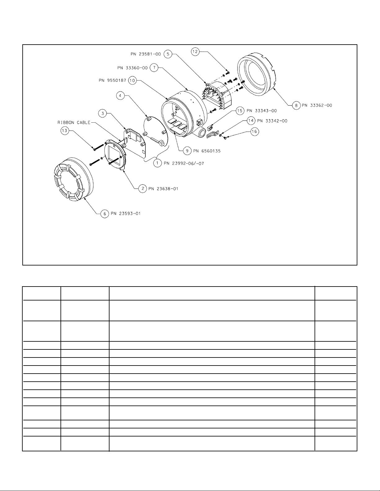
87
MODEL 5081-T SECTION 11.0
MAINTENANCE
FIGURE 11-2. Exploded View of Model 5081-T Transmitter
Three screws (part 13 in the drawing) hold the three circuit boards in place. Removing the screws allows the display board (part 2) and the
CPU board (part 3) to be easily removed. A ribbon cable connects the boards. The cable plugs into the CPU board and is permanently
attached to the display board. A 16 pin and socket connector holds the CPU and analog (part 4) boards together. Five screws hold the terminal block (part 5) to the center housing (part 7), and the 16 pins on the terminal block mate with 16 sockets on the back side of the analog board. Use caution when separating the terminal block from the analog board. The pin and socket connection is tight.
TABLE 11-1. Replacement Parts for Model 5081-T Transmitter
Location in Shipping
drawing PN Description Weight
1 23992-06 PCB stack for 5081-T-HT consisting of the CPU (part 3) and analog (part 4) 1 lb/0.5 kg
boards, display board is not included, CPU and analog boards are factorycalibrated as a unit and cannot be ordered separately
1 23992-07 PCB stack for 5081-T-FF consisting of the CPU (part 3) and analog (part 4) 1 lb/0.5 kg
boards, display board is not included, CPU and analog boards are factory-
calibrated as a unit and cannot be ordered separately
2 23652-01 LCD display PCB 1 lb/0.5 kg
5 33337-02 Terminal block 1 lb/0.5 kg
6 23593-01 Enclosure cover, front with glass window 3 lb/1.5 kg
7 33360-00 Enclosure, center housing 4 lb/1.5 kg
8 33362-00 Enclosure cover, rear 3 lb/1.0 kg
9 6560135 Desiccant in bag, one each 1 lb/0.5 kg
10 9550187 O-ring (2-252), one, front and rear covers each require an O-ring 1 lb/0.5 kg
12 note Screw, 8-32 x 0.5 inch, for attaching terminal block to center housing *
13 note Screw, 8-32 x 1.75 inch, for attaching circuit board stack to center *
housing
14 33342-00 Cover lock 1 lb/0.5 kg
15 33343-00 Locking bracket nut 1 lb/0.5 kg
16 note Screw, 10-24 x 0.38 inch, for attaching cover lock and locking bracket *
nut to center housing
NOTE: For information only. Screws cannot be purchased from Rosemount Analytical.
* Weights are rounded up to the nearest whole pound or 0.5 kg.
Page 94

88
12.1 OVERVIEW
This section is a general description of how the Model
5081-T Transmitter operates. This section is for those
users who desire a greater understanding of the transmitter’s operation.
12.2 CONDUCTIVITY
The conductivity sensor produces a “conductance signal”
that is proportional to the conductivity of the process
solution. The transmitter subtracts a baseline zero conductivity signal from the sensor signal and multiplies the
result by the cell constant and the cell factor. This
absolute conductivity is then corrected to the reference
temperature (usually 25°C) using the process temperature measured by a RTD located in the conductivity sensor. In the “n SALt”, “CAtion” and “rStvty” modes, the
Model 5081-T automatically calculates the amount of
correction needed.
In conductivity mode “LInEAr”, the microprocessor also
adjusts the amount of correction required for temperature
compensation by means of a temperature slope adjustment. This slope may be adjusted between 0 to 5%/°C
either manually via the Infrared Remote Control Keypad
or automatically during bench or process calibration. This
slope controls the amount of correction required in the
temperature compensation circuit, and is specific to the
process, giving you the most accurate conductivity reading possible.
12.3 HART COMMUNICATION
A MODAC (An application specific Integrated Circuit) is
connected across the current loop to read and transmit
the superimposed HART communications. The transmitter communicates via the HART protocol which uses an
industry standard BELL 202 frequency shift keying (FSK)
technique. This FSK signal is an AC signal, whose frequency is shifted higher or lower, depending upon the
condition of the digital signal (High or Low). This communication conforms to the Rosemount HART®specification and is used to configure and interrogate the transmitter.
12.4 OUTPUT LOGIC
Normal transmitter operation specifies that the output
tracks the process. However, the transmitter can be put
into other modes of operation.
These modes are:
Fault Mode (in the event of a fault). Sets the transmitter output to the value set during configuration. (Between
3.80 and 22.00mA). This mode is over-ridden by the
HOLD or TEST modes.
Hold Mode (manually placed in hold). Holds the output
current to the value set during configuration. This value
may be between 3.80 and 22.00 mA.
Hold mode supersedes the fault mode value. The current
output measurement is “Frozen” while the transmitter is
in the Hold Mode.
Test Mode (manually placed to test output). Can only
be accessed through the Program menu, and is only
active during the time the prompt is visible.
Output is set to the entered value and supersedes the
Hold and Fault modes, if such exist.
Test mode also disables the normal timeout feature (2
minutes after the last keystroke is made) for 20 minutes.
Timeout. The display will normally timeout and default to
the Main Display two (2) minutes after the last keystroke
is made.
While the output is being tested, or if a 2-point calibration
is being performed, the timeout is adjusted to 20 minutes.
If a custom curve is being programmed, no timeout will
be applied.
SECTION 12.0
THEORY OF OPERATION
MODEL 5081-T SECTION 12.0
THEORY OF OPERATION
Page 95

MODEL 5081-T SECTION 13.0
RETURN OF MATERIAL
SECTION 13.0
RETURN OF MATERIAL
13.1 GENERAL.
To expedite the repair and return of instruments, proper
communication between the customer and the factory
is important. Call 1-949-757-8500 for a Return
Materials Authorization (RMA) number.
13.2 WARRANTY REPAIR.
The following is the procedure for returning instruments still under warranty:
1. Call Rosemount Analytical for authorization.
2. To verify warranty, supply the factory sales order
number or the original purchase order number. In
the case of individual parts or sub-assemblies, the
serial number on the unit must be supplied.
3. Carefully package the materials and enclose your
“Letter of Transmittal” (see Warranty). If possible,
pack the materials in the same manner as they
were received.
4. Send the package prepaid to:
Emerson Process Management
Liquid Division
2400 Barranca Parkway
Irvine, CA 92606
Attn: Factory Repair
RMA No. ____________
Mark the package: Returned for Repair
Model No. ____
13.1 NON-WARRANTY REPAIR.
The following is the procedure for returning for repair
instruments that are no longer under warranty:
1. Call Rosemount Analytical for authorization.
2. Supply the purchase order number, and make
sure to provide the name and telephone number
of the individual to be contacted should additional
information be needed.
3. Do Steps 3 and 4 of Section 13.2.
NOTE
Consult the factory for additional information regarding service or repair.
89
Page 96

90
This page intentionally left blank.
Page 97

WARRANTY
Goods and part(s) (excluding consumables) manufactured by Seller are warranted to be free from defects in workmanship and material under normal use and service for a period of twelve (12) months from the date of shipment by Seller.
Consumables, pH electrodes, membranes, liquid junctions, electrolyte, O-rings, etc. are warranted to be free from defects
in workmanship and material under normal use and service for a period of ninety (90) days from date of shipment by Seller.
Goods, part(s) and consumables proven by Seller to be defective in workmanship and / or material shall be replaced or
repaired, free of charge, F.O.B. Seller's factory provided that the goods, parts(s), or consumables are returned to Seller's
designated factory, transportation charges prepaid, within the twelve (12) month period of warranty in the case of goods
and part(s), and in the case of consumables, within the ninety (90) day period of warranty. This warranty shall be in effect
for replacement or repaired goods, part(s) and consumables for the remaining portion of the period of the twelve (12)
month warranty in the case of goods and part(s) and the remaining portion of the ninety (90) day warranty in the case of
consumables. A defect in goods, part(s) and consumables of the commercial unit shall not operate to condemn such commercial unit when such goods, parts(s) or consumables are capable of being renewed, repaired or replaced.
The Seller shall not be liable to the Buyer, or to any other person, for the loss or damage, directly or indirectly, arising
from the use of the equipment or goods, from breach of any warranty or from any other cause. All other warranties,
expressed or implied are hereby excluded.
IN CONSIDERATION OF THE STATED PURCHASE PRICE OF THE GOODS, SELLER GRANTS ONLY THE ABOVE
STATED EXPRESS WARRANTY. NO OTHER WARRANTIES ARE GRANTED INCLUDING, BUT NOT LIMITED TO,
EXPRESS AND IMPLIED WARRANTIES OF MERCHANTABILITY AND FITNESS FOR A PARTICULAR PURPOSE.
RETURN OF MATERIAL
Material returned for repair, whether in or out of warranty, should be shipped prepaid to:
Emerson Process Management
Liquid Division
2400 Barranca Parkway
Irvine, CA 92606
The shipping container should be marked:
Return for Repair
Model
_______________________________
The returned material should be accompanied by a letter of transmittal which should include the following information
(make a copy of the "Return of Materials Request" found on the last page of the Manual and provide the following thereon):
1. Location type of service, and length of time of service of the device.
2. Description of the faulty operation of the device and the circumstances of the failure.
3. Name and telephone number of the person to contact if there are questions about the returned material.
4. Statement as to whether warranty or non-warranty service is requested.
5. Complete shipping instructions for return of the material.
Adherence to these procedures will expedite handling of the returned material and will prevent unnecessary additional
charges for inspection and testing to determine the problem with the device.
If the material is returned for out-of-warranty repairs, a purchase order for repairs should be enclosed.
Page 98

Credit Cards for U.S. Purchases Only.
The right people,
the right answers,
right now.
ON-LINE ORDERING NOW AVAILABLE ON OUR WEB SITE
http://www.raihome.com
Specifications subject to change without notice.
Emerson Process Management
Liquid Division
2400 Barranca Parkway
Irvine, CA 92606 USA
Tel: (949) 757-8500
Fax: (949) 474-7250
http://www.raihome.com
© Rosemount Analytical Inc. 2006
 Loading...