

Page 1

Application Guidelines
Copeland Stream
™
Semi-Hermetic Compressors
4MF-13X to 6MK-50X
Page 2

AGL_Stream_ST_4M_6M_E_Rev01
About these guidelines ............................................................................................... 1
1 Safety instructions ........................................................................................... 1
1.1 Icon explanation ............................................................................................................... 1
1.2 Safety statements ............................................................................................................ 1
1.3 General instructions ......................................................................................................... 2
2 Product description ......................................................................................... 3
2.1 General information about Copeland Stream™ semi-hermetic compressors ................. 3
2.2 Nomenclature ................................................................................................................... 3
2.3 Nameplate information ..................................................................................................... 4
2.4 Application range ............................................................................................................. 4
2.4.1 Qualified refrigerants and oils .............................................................................. 4
2.4.2 Application limits ................................................................................................... 5
2.5 Design features ................................................................................................................ 5
2.5.1 Compressor construction ..................................................................................... 5
2.5.2 Compressor cooling ............................................................................................. 5
2.5.3 Demand cooling ................................................................................................... 5
2.5.4 Unloaded start ...................................................................................................... 5
2.5.5 Capacity control .................................................................................................... 6
2.5.6 Oil pumps ............................................................................................................. 6
2.5.7 Oil pressure .......................................................................................................... 6
2.5.8 Oil circulation ........................................................................................................ 6
2.5.9 Oil level ................................................................................................................. 6
3 Installation ........................................................................................................ 7
3.1 Compressor handling ....................................................................................................... 7
3.1.1 Delivery................................................................................................................. 7
3.1.2 Transport and storage .......................................................................................... 7
3.1.3 Positioning and securing ...................................................................................... 7
3.1.4 Installation location ............................................................................................... 8
3.1.5 Mounting parts ...................................................................................................... 8
3.2 Pressure safety controls .................................................................................................. 8
3.2.1 High-pressure control ........................................................................................... 8
3.2.2 Low-pressure control ............................................................................................ 8
3.2.3 Maximum allowable pressures ............................................................................. 8
3.3 Brazing procedure ............................................................................................................ 9
3.4 Screens ............................................................................................................................ 9
4 Electrical connection ..................................................................................... 10
4.1 General recommendations............................................................................................. 10
4.2 Electrical installation ...................................................................................................... 10
4.2.1 Part-winding motors (YY/Y) – Code A ................................................................ 10
4.2.2 Star / Delta motors (Y/∆) – Code E .................................................................... 10
Page 3

AGL_Stream_ST_4M_6M_E_Rev01
4.2.3 Terminal box isolators and jumper position........................................................ 11
4.3 Wiring diagrams ............................................................................................................. 11
4.3.1 Compressors with Next Generation CoreSense module ................................... 11
4.3.2 Compressors with CoreSense Protection module ............................................. 14
4.3.3 Compressors with former CoreSense Diagnostics module ............................... 16
4.4 Protection devices .......................................................................................................... 17
4.5 Next Generation CoreSense™ ...................................................................................... 18
4.5.1 Next Gen CoreSense specifications .................................................................. 18
4.5.2 Next Gen CoreSense features ........................................................................... 18
4.6 CoreSense™ Protection ................................................................................................ 19
4.6.1 Motor protection ................................................................................................. 19
4.6.2 Oil pressure control ............................................................................................ 20
4.7 CoreSense™ Diagnostics (until December 2019 included) .......................................... 21
4.8 Crankcase heaters ......................................................................................................... 22
5 Starting up & operation.................................................................................. 24
5.1 Leak test......................................................................................................................... 24
5.2 System evacuation ......................................................................................................... 24
5.3 Preliminary checks – Pre-starting .................................................................................. 24
5.4 Charging procedure ....................................................................................................... 24
5.5 Initial start-up ................................................................................................................. 25
5.6 Minimum run time .......................................................................................................... 25
5.7 Recommended inverter range ....................................................................................... 25
6 Maintenance & repair ..................................................................................... 26
6.1 Provisions of legislation & leak check requirements ...................................................... 26
6.2 Exchanging the refrigerant ............................................................................................. 27
6.3 Replacing a compressor ................................................................................................ 27
6.4 Lubrication and oil removal ............................................................................................ 27
6.5 Oil additives ................................................................................................................... 28
6.6 Unbrazing system components ..................................................................................... 28
7 Dismantling & disposal .................................................................................. 28
Appendix 1: Stream compressor connections ........................................................ 29
Appendix 2: Tightening torques in Nm .................................................................... 30
Disclaimer .................................................................................................................. 30
Page 4
AGL_Stream_ST_4M_6M_E_Rev01 1
About these guidelines
The purpose of these application guidelines is to provide guidance in the application of Copeland™
Stream™ semi hermetic compressors 4M* and 6M*. They are intended to answer the questions
raised while designing, assembling and operating a system with these products.
Besides the support they provide, the instructions listed herein are also critical for the proper and
safe functioning of the compressors. The performance and reliability of the product may be impacted
if the product is not used according to these guidelines or is misused.
These application guidelines cover stationary applications only. For mobile applications, contact
Application Engineering as other considerations may apply.
1 Safety instructions
Copeland™ semi-hermetic compressors are manufactured according to the latest European safety
standards. Particular emphasis has been placed on the user’s safety.
These compressors are intended for installation in systems according to the Machinery Directive MD
2006/42/EC. They may be put to service only if they have been installed in these systems according
to instructions and conform to the corresponding provisions of legislation. For relevant standards
please refer to the Manufacturer’s Declaration, available at www.climate.emerson.com/en-gb.
These instructions should be retained throughout the lifetime of the compressor.
You are strongly advised to follow these safety instructions.
1.1 Icon explanation
WARNING
This icon indicates instructions to
avoid personal injury and material
damage.
CAUTION
This icon indicates instructions to avoid
property damage and possible
personal injury.
High voltage
This icon indicates operations with a
danger of electric shock.
IMPORTANT
This icon indicates instructions to avoid
malfunction of the compressor.
Danger of burning or frost burn
This icon indicates operations with a
danger of burning or frost burn.
NOTE
This word indicates a recommendation
for easier operation.
Explosion hazard
This icon indicates operations with a
danger of explosion.
1.2 Safety statements
▪ Refrigerant compressors must be employed only for their intended use.
▪ Only qualified and authorized HVAC or refrigeration personnel are permitted to install,
commission and maintain this equipment.
▪ Electrical connections must be made by qualified electrical personnel.
▪ All valid standards for connecting electrical and refrigeration equipment must be
observed.
▪ The national legislation and regulations regarding personnel protection must be observed.
Use personal safety equipment. Safety goggles, gloves,
protective clothing, safety boots and hard hats should be worn
where necessary.
Page 5
2 AGL_Stream_ST_4M_6M_E_Rev01
1.3 General instructions
WARNING
System breakdown! Personal injuries! Never install a system in the field
and leave it unattended when it has no charge, a holding charge, or with the
service valves closed without electrically locking out the system.
System breakdown! Personal injuries! Only approved refrigerants and
refrigeration oils must be used.
WARNING
High shell temperature! Burning! Do not touch the compressor until it has
cooled down. Ensure that other materials in the area of the compressor do not
get in touch with it. Lock and mark accessible sections.
CAUTION
Overheating! Bearing damage! Do not operate compressor without
refrigerant charge or without it being connected to the system.
CAUTION
Contact with POE! Material damage! POE lubricant must be handled
carefully and the proper protective equipment (gloves, eye protection, etc.)
must be used at all times. POE must not come into contact with any surface
or material that it might damage, including without limitation, certain polymers,
eg, PVC/CPVC and polycarbonate.
IMPORTANT
Transit damage! Compressor malfunction! Use original packaging. Avoid
collisions and tilting.
Page 6
AGL_Stream_ST_4M_6M_E_Rev01 3
2 Product description
2.1 General information about Copeland Stream™ semi-hermetic compressors
These guidelines cover Copeland Stream™ semi-hermetic compressors. The semi-hermetic
reciprocating compressor family consists of different ranges. The Stream™ series of 4M* and 6M*
models ranges from 13 hp to 50 hp.
Model
Nominal
horsepower
[cv]
Displa-
cement
[m3/h]
High
temperature
(1)
Medium
temperature
(2)
Low
temperature
(3)
Net
weight
[kg]
Footprint
[mm]
Cooling
capacity
[kW]
COP
Cooling
capacity
[kW]
COP
Cooling
capacity
[kW]
COP
R134a
R448A / R449A
R448A / R449A
4MF-13x
13
62
33.20
3.28
28.00
2.17
8.60
1.37
177
381 x 305
4MA-22X
22
34.60
3.41
31.80
2.54
8.24
1.34
178
4ML-15X
15
71
39.70
3.30
36.10
2.40
10.90
1.43
180
4MH-25X
25
39.90
3.30
36.20
2.44
9.93
1.31
187
4MM-20X
17
78
43.50
3.28
39.40
2.36
12.25
1.44
182
4MI-30X
27
43.70
3.30
41.00
2.48
11.30
1.38
188
4MT-22X
22
88
49.30
3.26
44.50
2.36
14.00
1.45
183
4MJ-33X
30
48.60
3.30
45.10
2.43
12.70
1.38
190
4MU-25X
25
99
55.10
3.20
49.40
2.28
14.95
1.39
186
4MK-35X
32
54.50
3.17
50.70
2.37
14.40
1.35
202
6MM-30X
27
120
65.80
3.21
59.00
2.32
18.35
1.40
215
6MI-40X
35
64.70
3.16
61.90
2.48
17.85
1.38
219
6MT-35X
32
135
73.60
3.17
65.30
2.28
20.60
1.41
221
6MJ-45X
40
72.60
3.16
69.10
2.43
20.40
1.42
223
6MU-40X
40
153
81.10
3.07
76.30
2.41
23.20
1.42
225
6MK-50X
50
80.70
3.05
76.40
2.39
22.10
1.35
230
1)
R134a: Evaporating 5 °C, condensing 50 °C, suction superheat 10 K, subcooling 0 K
2)
R448A / R449A: Evaporating -10 °C, condensing 45 °C, suction gas temperature 20 °C, subcooling 0 K
3)
R448A / R449A: Evaporating -35 °C, condensing 40 °C, suction gas temperature 0 °C, subcooling 0 K
Table 1: Stream compressors range and performance
Stream compressors are suitable for a wide range of applications in the form of either single
compressors, condensing units or as multi-compressor equipment.
NOTE: The compressor is only one component which must be combined with many others to
build a functional and efficient refrigeration system. Therefore, the information in this manual
relates to Copeland Stream semi-hermetic compressors with standard equipment and
accessories only.
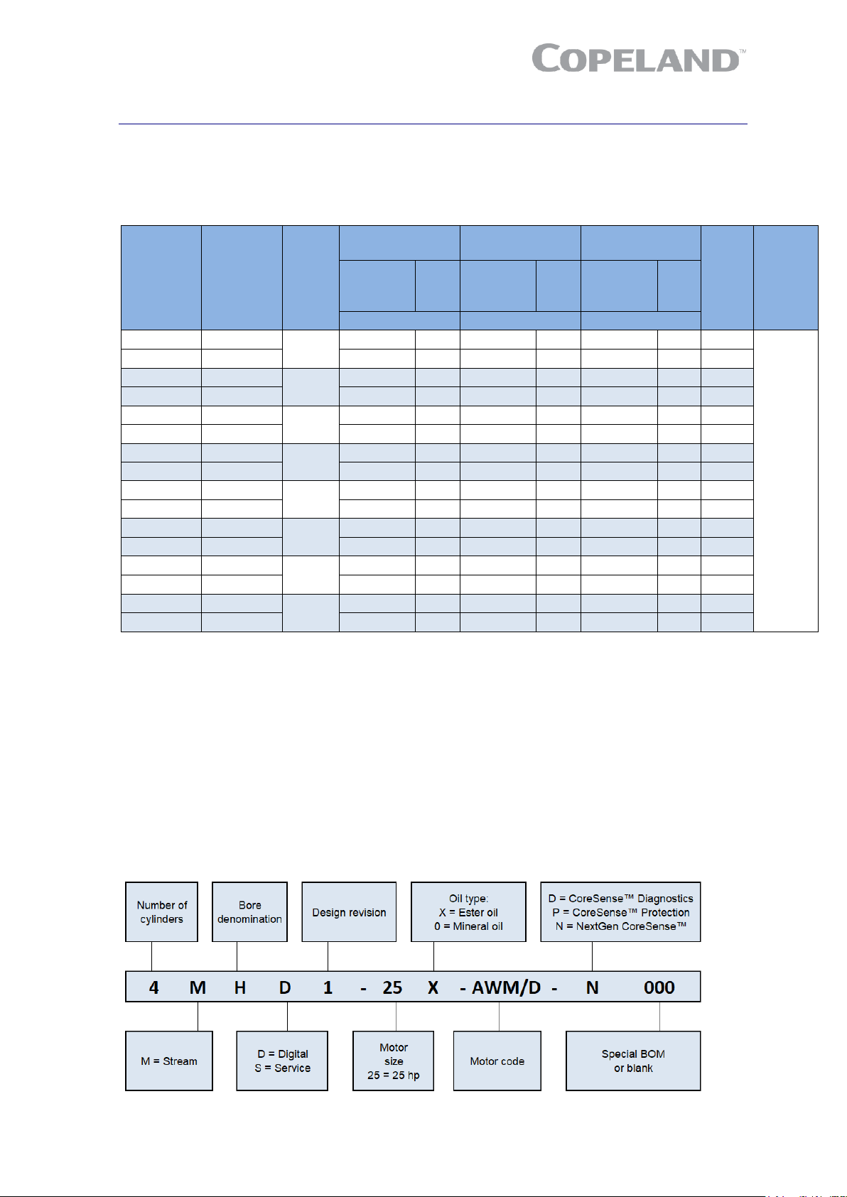
2.2 Nomenclature
The model designation contains the following technical information about Stream compressors:
Page 7
4 AGL_Stream_ST_4M_6M_E_Rev01
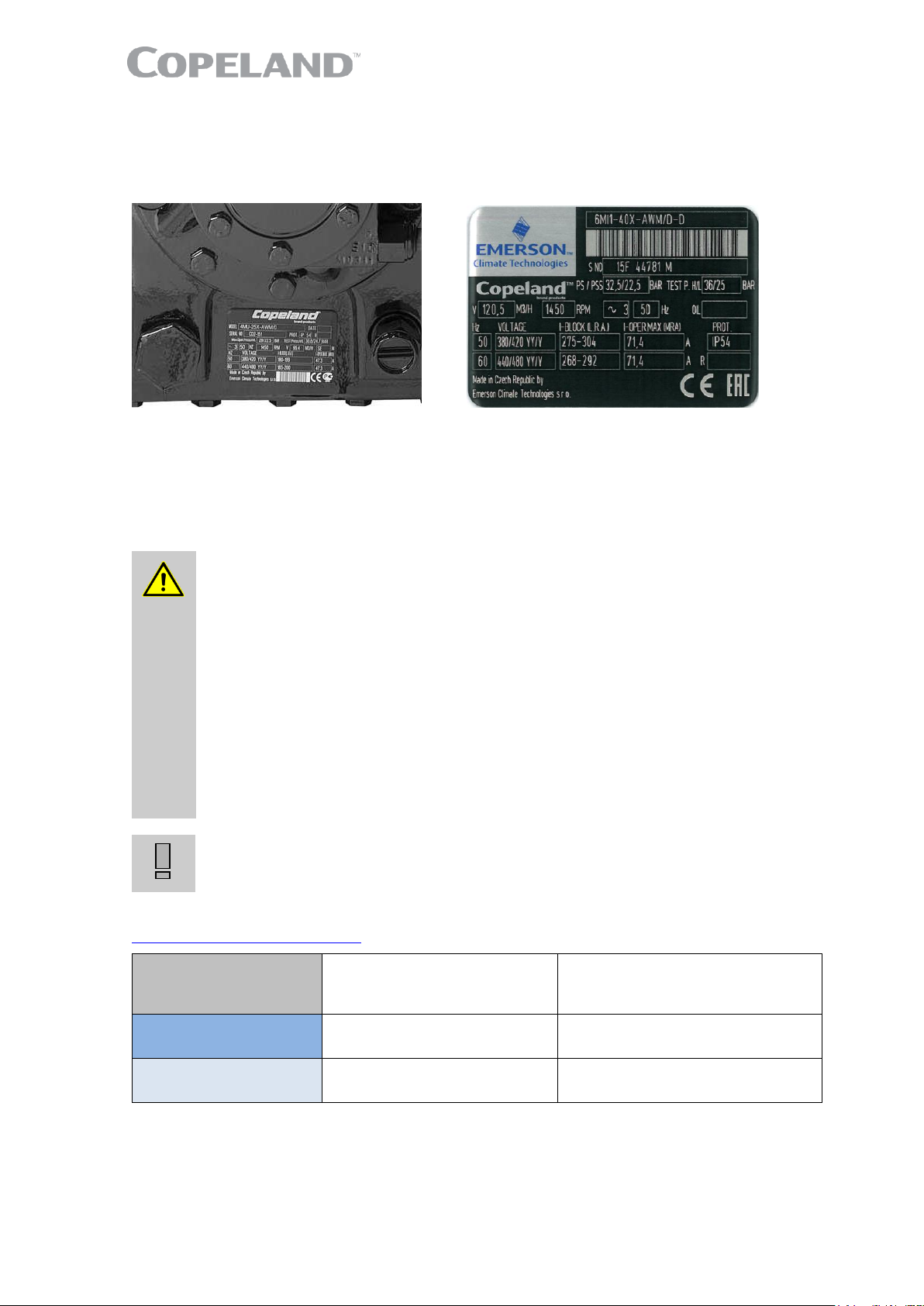
2.3 Nameplate information
All important information for identification of the compressor is printed on the nameplate located
below the compressor oil pump. The type of refrigerant used should be stamped on the nameplate
by the installer.
Figure 1: Nameplate location
The year and month of production are shown as part of the serial number (Jan = A, Feb = B, … Dec
= L).
2.4 Application range
2.4.1 Qualified refrigerants and oils
WARNING
Use of R450A and R513A refrigerants! Risk of compressor damage!
Refrigerant migration of R450A or R513A into the compressor crankcase
could cause low oil viscosity, which could lead to compressor damage. When
using R450A or R513A it is critical to meet the following requirements:
▪ maintain adequate superheat settings with a minimum superheat of
8-10K;
▪ no liquid refrigerant migration into the compressor at any time, especially
during standstill, during or after defrost, or after reverse mode for example
in heat pumps;
▪ pumpdown is recommended;
▪ the use of a crankcase heater is mandatory;
▪ retrofit to R450A and R513A is only allowed for compressors which are
approved for these refrigerants.
Contact Application Engineering for any further information.
IMPORTANT
It is essential that the glide of refrigerant blends (primarily R407C) is carefully
considered when adjusting pressure and superheat controls.
Oil recharge values can be taken from Copeland™ brand products Select software available at
www.climate.emerson.com/en-gb.
Qualified refrigerants
R134a, R404A, R407A, R407C,
R407F, R448A, R449A, R450A,
R507, R513A
R22
Copeland brand
products standard oils
Emkarate RL 32 3MAF
Suniso 3 GS
Servicing oils
Emkarate RL 32 3MAF
Mobil EAL Arctic 22 CC
Shell 22-12, Suniso 3 GS
Fuchs Reniso KM 32, Capella WF32
Table 2: Qualified refrigerants and oils for recharging and topping up
Page 8

AGL_Stream_ST_4M_6M_E_Rev01 5
To recharge:
▪ When the compressor is completely empty of oil, the amount of oil to be "recharged" is typically
0.12 litre less than the original oil charge (oil will already be present in the system).
To top up:
▪ During commissioning, planned maintenance or servicing, add oil so that the compressor oil level
is between min ¼ and max ¾ of sight glass.
2.4.2 Application limits
For application envelopes please refer to Copeland brand products Select software at
www.climate.emerson.com/en-gb.
2.5 Design features
2.5.1 Compressor construction
All compressors are fitted with Stream valve plates which cannot be dismantled. To maintain the high
capacity of these compressors in case of exchange, the correct valve-plate-to-body gasket must
always be selected.
Each cylinder head has 2 plugged 1/8" - 27 NPTF
tapped holes for connecting high-pressure
switches.
These high-pressure switches must be calibrated
and tested before putting the compressor into
service. They must stop the compressor if the
allowable pressure is exceeded.
The complete cylinder head is under discharge
pressure.
Figure 2
2.5.2 Compressor cooling
Compressor motors must always be cooled, and cylinder head cooling may also be needed at certain
operating conditions.
All Stream compressors are suction gas-cooled. With suction gas-cooled compressors, the motor is
cooled by refrigerant gas that is led over the motor. An additional fan may be required depending
upon the operating conditions – see Copeland brand products Select software at
www.climate.emerson.com/en-gb.
2.5.3 Demand cooling
"Demand Cooling" as the term implies means liquid refrigerant injection on demand.
For low temperature applications with R407F, R407A, R448A, R449A and R22, Demand Cooling
can be required on the following compressors:
4MF-13X 4ML-15X 4MM-20X 4MT-22X 4MU-25X
6MM-30X 6MT-35X 6MU-40X
NOTE: R22 is no longer allowed for new refrigeration systems in Europe.
2.5.4 Unloaded start
With direct starting the motor of a compressor is switched directly into the mains by means of a
switch. The resulting breakaway starting current amounts to multiple times the rated motor current
operating maximum, without consideration being given to transient phenomena.
In the case of high-powered motors the breakaway starting currents become so large that they lead
to disruptive voltage dips in the mains. The compressors that are subject to current limitation must
therefore by all means be equipped with starting load reduction to guarantee perfect starting even
when the voltages amount to less than approximately 85% of the voltage on the nameplate.
Page 9

6 AGL_Stream_ST_4M_6M_E_Rev01
2.5.5 Capacity control
For 4M* and 6M* compressors a mechanical capacity control is available. The system used is
blocked suction. Be aware that unloaded operation changes the application range of the compressor.
NOTE: For the application range of compressors with capacity control, refer to Technical
Information D7.21.2 "Stream Semi-Hermetic Compressor Capacity Control".
2.5.6 Oil pumps
The oil pumps used for Stream compressors are independent of their rotating direction.
On compressors with Next Generation CoreSense™ (-N) or formerly delivered with CoreSense™
Diagnostics (-D), the oil pump integrates an electronic switch to ensure the oil pressure safety
functionality.
Compressors with CoreSense™ Protection (-P) are designed to accommodate fittings for an OPS2,
FD-113ZU or Sentronic oil safety system, or a standard oil pressure switch (OPS2 oil sensor included
in the oil pump).
2.5.7 Oil pressure
Normal oil pressure is between 1.05 and 4.2 bar higher than crankcase pressure. Net oil pressure
can be read by connecting two pressure gauges to the compressor and comparing the readings.
One gauge should be connected to the oil pump. The second gauge should be connected to the
crankcase (T-fitting instead of plug on the compressor crankcase) or the suction service valve.
During irregular operating conditions, eg, a blockage of the suction filter, the pressure measured at
the suction shut-off valve of the compressor may differ widely from that measured at the crankcase.
Therefore pressure drops have to be avoided.
2.5.8 Oil circulation
Oil returns with the suction gases through a suction strainer and separates in the motor chamber
reaching the crankcase by way of oil return relief valve in the partition between motor housing and
crankcase. This relief valve closes on compressor start-up due to the pressure difference arising
between motor side and crankcase, thus slowing down pressure decrease in the crankcase over a
certain period of time. It reduces the foaming of the oil/refrigerant mixture that would occur if the
pressure decreased rapidly. The valve does not reopen until the pressure has been equalized by
means of a crankcase ventilating valve. This second valve connects the crankcase and suction side
cylinder head. It reduces the pressure difference by means of a very small bore in the plate of the
valve so slowly that oil foams less and only limited oil/refrigerant foam is transferred to the oil pump.
Four-cylinder compressors have one crankcase ventilating valve on the left cylinder bank whereas
six-cylinder compressors have two ventilating valves on the left and right cylinder banks.
2.5.9 Oil level
All compressors are delivered with sufficient oil for normal operation – see Table 2. The optimum oil
level should be checked by operating the compressor until the system is stable and then comparing
the sight glass reading with the appropriate diagram below. The oil level should be min ¼ and max
¾ of the sight glass.
For service compressors when an oil regulator is used the oil level should be min ¼ and max ¾ of
the sight glass. The level can also be checked within 10 seconds of compressor shutdown.
For 4M* and 6M* compressors a higher oil level may be accepted when an oil regulator is in use
because the oil separator will reduce excessive oil circulation.
Figure 3: Sight glass reading on 4M* and 6M* compressors
Page 10
AGL_Stream_ST_4M_6M_E_Rev01 7
3 Installation
WARNING
High pressure! Injury to skin and eyes possible! Be careful when opening
connections on a pressurized item.
3.1 Compressor handling
3.1.1 Delivery
Please check whether the delivery is correct and complete. Any deficiency should be reported
immediately in writing.
Standard delivery:
▪ Suction and discharge shut-off valves
▪ Oil charge, oil sight glass
▪ Mounting kit
▪ Next Generation CoreSense™, CoreSense™ Diagnostics or CoreSense™ Protection module
▪ Holding charge up to 2.5 bar(g) (dry air)
3.1.2 Transport and storage
WARNING
Risk of collapse! Personal injuries! Move compressors only with
appropriate mechanical or handling equipment according to weight. Keep in
the upright position. Respect stacking loads according to Figure 4. Check the
tilting stability and if needed take action to ensure the stability of the stacked
loads. Keep the packaging dry at all times.
Respect the maximum number of identical packages which may be stacked on one
another, where "n" is the limiting number:
▪ Transport: n = 1
▪ Storage: n = 1
Figure 4: Maximum stacking loads for transport and storage
NOTE: The compressor is pre-charged with dry air to avoid any moisture contamination.
3.1.3 Positioning and securing
IMPORTANT
Handling damage! Compressor malfunction! Only use the lifting eyes
whenever the compressor requires positioning. Using discharge or suction
connections for lifting may cause damage or leaks.
If possible, the compressor should be kept horizontal during handling.
For safety reasons two lifting eyes should be fitted before moving a compressor (½" - 13 UNC).
Otherwise refer to drawings on Figure 5 to see how to apply other lifting methods.
4M* 6M*
max. 220 kg max. 260 kg
Figure 5
Page 11
8 AGL_Stream_ST_4M_6M_E_Rev01
In order to avoid refrigerant leaks or other damage the compressors should not be lifted by the service
valves or other accessories.
3.1.4 Installation location
Ensure the compressors are installed on a solid level base.
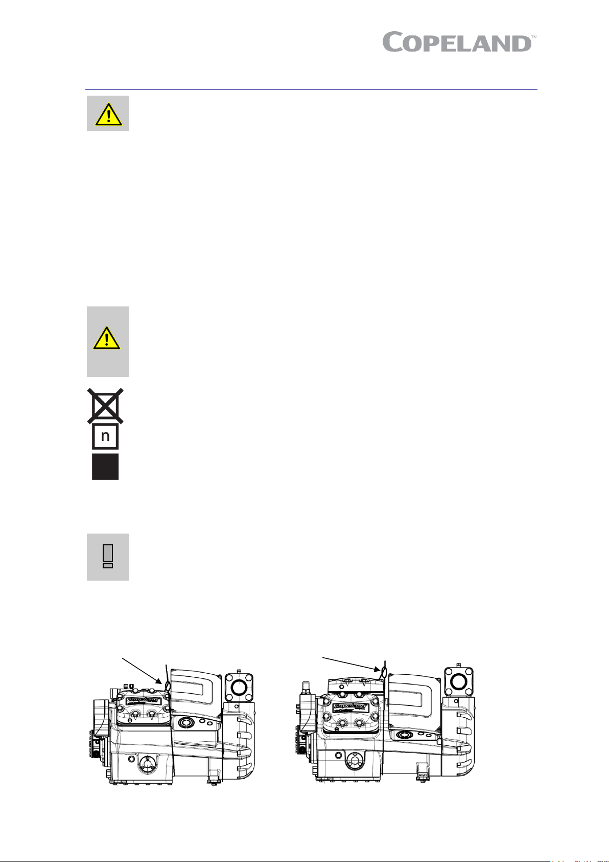
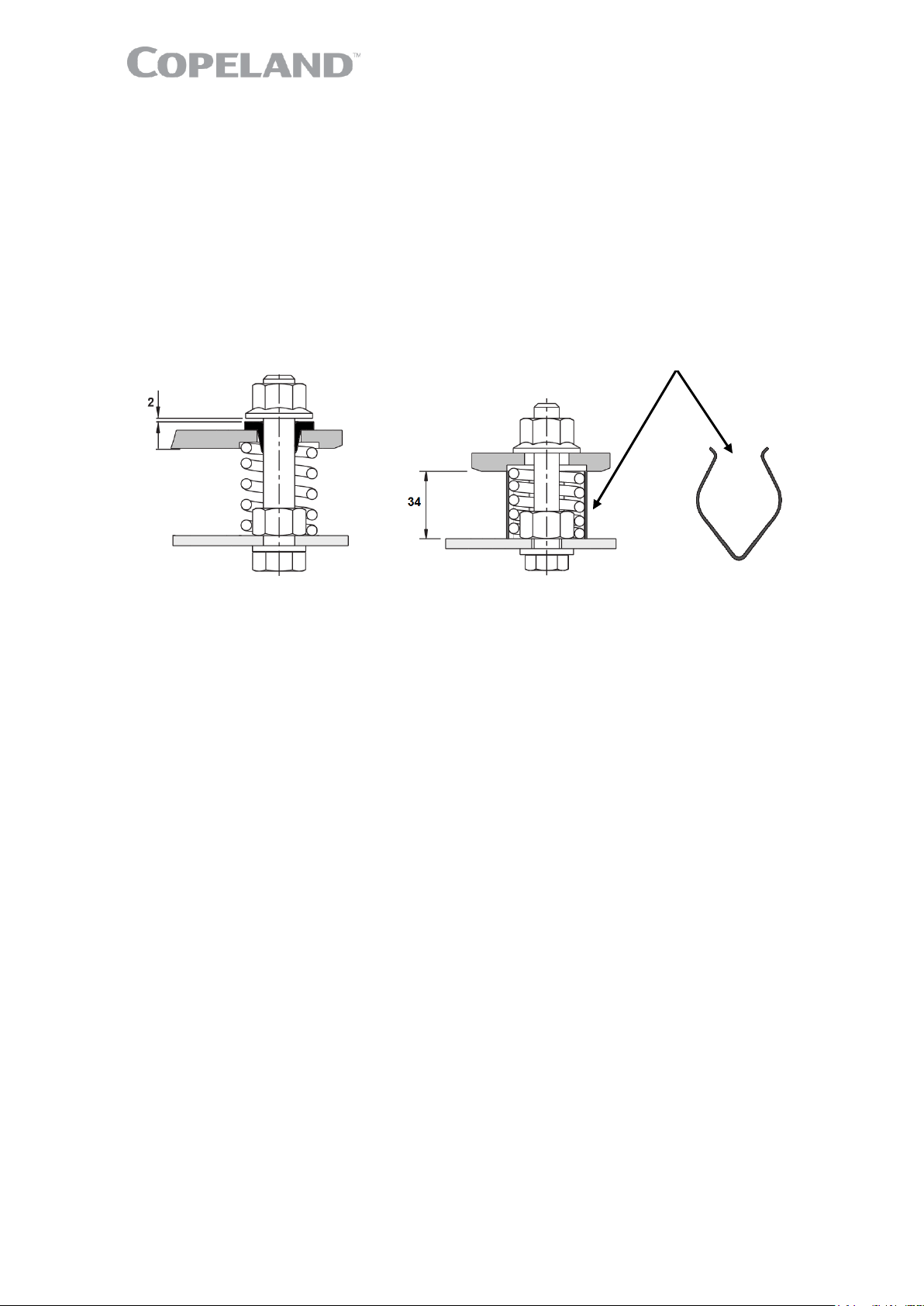
3.1.5 Mounting parts
To minimize vibration and start/stop impulses flexible mounting should be used. For this purpose,
one set of spring mounting parts for each of the Stream models is delivered with each 4M* and 6M*
compressor.
Due to differences in weight (cylinder / motor side), different springs have to be used on both sides.
Springs have different colours for easier identification: violet on motor side and orange on cylinder
side.
Operational position Transport position
Figure 6: Position of vibration dampers during transport and operation
When Stream compressors are mounted in racks rubber mounting parts should be used.
A compressor may be rigidly mounted, ie, without springs. In this case more shock and vibration
loading will be transmitted to the frame.
Unevenness in the mounting surface will have to be compensated by the rack and/or the compressor
bottom plate/feet. Excessive unevenness can result in too high mechanical stress to the system and
could damage the compressor or rack. Therefore, the flatness of the mounting location is essential.
In addition, both vibration/shock and mechanical stress to compressor can be avoided by using
rubber mounting parts.
If the installation requires a very high level of vibration absorption, additional vibration absorbers –
available on the market – can be fitted between the rails and the foundation.
3.2 Pressure safety controls
3.2.1 High-pressure control
A high-pressure control with a maximum cut-out setting of 28.8 bar(g) is required.
The high-pressure cut-out should have a manual reset feature for the highest level of system
protection.
3.2.2 Low-pressure control
The normal minimum cut-out setting is 0.1 bar(g) for R404A.
The low-pressure cut-out should have a manual reset feature for the highest level of system
protection.
3.2.3 Maximum allowable pressures
The maximum allowable pressures according to EN 12693 shown on the compressor nameplate are
obligatory and must not be exceeded.
▪ High-pressure side (HP): 28.0 bar (g) (up to S/N 14K46143M)
32.5 bar (g) (from S/N 14K46144M onwards)
▪ Low-pressure side (LP): 22.5 bar
Transport clamp
Page 12

AGL_Stream_ST_4M_6M_E_Rev01 9
NOTE: The compressor operating range may be restricted for various reasons. Check the
application range limitations in Copeland brand products Select software at
www.climate.emerson.com/en-gb.
3.3 Brazing procedure
IMPORTANT
Blockage! Compressor breakdown! Maintain a flow of oxygen-free nitrogen
through the system at very low pressure during brazing. Nitrogen displaces
the air and prevents the formation of copper oxides in the system. If allowed
to form, the copper oxide material can later be swept through the system and
block screens such as those protecting capillary tubes, thermal expansion
valves, and accumulator oil return holes.
Contamination or moisture! Bearing failure! Do not remove the plugs until
the compressor is set into the unit. This minimises any entry of contaminants
and moisture.
Refer to Figure 7 and procedure below for the brazing of the suction and discharge lines:
▪ The copper-coated steel tubes on Stream
compressors can be brazed in approximately the same
manner as any copper tube.
▪ Recommended brazing material: any silfos
material is recommended, preferably with a minimum of
5% silver. However, 0% silver is acceptable.
▪ Be sure tube fitting inner diameter and tube outer
diameter are clean prior to assembly.
▪ Using a double-tipped torch, apply heat in area 1.
▪ As the tube approaches brazing temperature,
move the torch flame to area 2.
▪ Heat area 2 until braze temperature is attained, moving the torch up and down and rotating
around the tube as necessary to heat the tube evenly. Add braze material to the joint while
moving the torch around the joint to flow braze material around the circumference.
▪ After the braze material flows around the joint, move the torch to heat area 3. This will draw the
braze material down into the joint. The time spent heating area 3 should be minimal.
▪ As with any brazed joint, overheating may be detrimental to the final result.
To disconnect:
▪ Heat joint areas 2 and 3 slowly and uniformly until the braze material softens and the tube can
be pulled out of the fitting.
To reconnect:
▪ Recommended brazing materials: Silfos with minimum 5% silver or silver braze used on other
compressors.
3.4 Screens
CAUTION
Screen blocking! Compressor breakdown! Use screens with at least
0.6 mm openings.
The use of screens finer than 30 x 30 meshes (0.6 mm openings) anywhere in the system should be
avoided with these compressors. Field experience has shown that finer mesh screens used to protect
thermal expansion valves, capillary tubes or accumulators can become temporarily or permanently
plugged with normal system debris and block the flow of either oil or refrigerant to the compressor.
Such blockage can result in compressor failure.
Figure 7: Suction tube brazing areas
Page 13

10 AGL_Stream_ST_4M_6M_E_Rev01
4 Electrical connection
4.1 General recommendations
The compressor terminal box has a wiring diagram on the inside of its cover. Before connecting the
compressor, ensure that the supply voltage, the phases and the frequency match the nameplate
data.
The knockouts have to be removed before the electrical glands can be installed. First make sure that
the terminal box is closed with the terminal box cover. We recommend to use a subland twist driller
to avoid any damage to the box while removing the knockouts.
Figure 8
4.2 Electrical installation
All compressors can be started Direct-On-Line.
The position of bridges required for Direct-On-Line start (depending on type of motor and/or mains
voltage) is shown in paragraph 4.2.3 "Terminal box isolators and jumper position".
4.2.1 Part-winding motors (YY/Y) – Code A
A part-winding motor contains two separate windings (2/3 + 1/3) which are internally connected in
star and operated in parallel. You cannot change the voltage by changing the electrical connections
as the motor is only suitable for one voltage.
The first part-winding, ie, the 2/3 winding on terminals 1-2-3, can be used for part-winding start
(remove the bridges!). After a time delay of 1 ± 0.1 seconds the second part-winding, ie, the 1/3
winding on terminals 7-8-9, must be brought on line.
4.2.2 Star / Delta motors (Y/∆) – Code E
This motor is interchangeable for star (Y) or delta (∆) operation by means of bridges. It is suitable for
two voltages, eg, 230 V in delta, 400 V in star connection. If the supply voltage and the nominal
voltage of the motor in ∆-connection are identical, the star connection motor can also be used for
starting (remove the bridges!).
Twist driller
Page 14

AGL_Stream_ST_4M_6M_E_Rev01 11
4.2.3 Terminal box isolators and jumper position
Part-winding motors can be connected direct-on-line or part-winding start.
Part-winding motor
Y – Y
Code A
Direct-on-line start
Y - Y
Part-winding start
First start step 1–2-3
Y - Y
Star / Delta motors can be connected direct-on-line or Star / Delta start.
Star / Delta motor
Y - ∆
Code E
Direct-on-line start
∆
Direct-on-line start
Y
Star / Delta start
∆
4.3 Wiring diagrams
4.3.1 Compressors with Next Generation CoreSense module
4.3.1.1 Basic protection
The Next Generation CoreSense module version is originally delivered with the basic modules preconnected.
Figure 9: Basic module connections
Page 15

12 AGL_Stream_ST_4M_6M_E_Rev01
4.3.1.2 Wiring diagram for part-winding motors (AW…)
Figure 10: Wiring diagram – Part-winding motors (AW…)
4.3.1.3 Wiring diagram for Star / Delta motors (EW…)
Figure 11: Wiring diagram – Star / Delta motors (EW…)
Page 16

AGL_Stream_ST_4M_6M_E_Rev01 13
4.3.1.4 Wiring diagram (2nd part) for part-winding and Star / Delta motors (AW… and EW…)
Legend
B1 ....... Discharge gas sensor K11 ..... Time relay for part-winding (if used)
B2 ....... Oil level watch (Traxoil) M2 ...... Fan motor
B3 ....... Oil differential pressure switch (OPS) Q11 ..... Compressor contactor
B11 ..... High-pressure switch Q12 ..... Compressor contactor Y (if Y/Δ start)
B12 ..... Low-pressure switch Q13 ..... Compressor contactor Δ (if Y/Δ start)
CTR2 .. DP gateway Q14 ..... Compressor contactor 2nd part-winding
E1 ....... Heater (if used)
F1, F2, F3 Compressor fuses Q15 ..... Fan contactor
F4, F5 . Fan fuses Y21 ..... Solenoid valve capacity control 1
F6 ....... CoreSense and heater fuse Y22 ..... Solenoid valve capacity control 2
F7 ....... Control circuit fuse T1 ....... Current sensor
H1 ....... Diagnose LED
AR ....... Alarm relay OPS .... Oil differential pressure protection
CH ...... Control oil heater OW ..... Digital oil level watch
CM ...... Current monitoring PM ...... Phase monitoring
DGT .... Discharge gas temperature monitoring PS ....... Power supply
DS ....... Demand signal PTC .... Motor thermic protection
SB1 ..... Reset button
Figure 12: Wiring diagram – Part-winding and Star / Delta motors (AW… and EW…)
Page 17

14 AGL_Stream_ST_4M_6M_E_Rev01
4.3.2 Compressors with CoreSense Protection module
4.3.2.1 Wiring diagram for part-winding motors (AW…)
Part-winding motors can be connected direct-on-line or part-winding start.
Legend
A1 ....... CoreSense Protection module K1 ........ Contactor M1
A2 ....... OPS2 Oil pressure switch K4 ........ Contactor M1 for second part-winding
A5 ....... Compressor terminal box M21 ..... Fan motor / condenser
F6 ....... Fuse for control circuit R2 ........ Crankcase heater
F7 ....... Fuse for control circuit Y21 ...... Solenoid valve capacity control 1
F8 ....... Fuse for control circuit Y22 ...... Solenoid valve capacity control 2
F10 ..... Thermal protection switch M21 Y3 ........ Solenoid valve unloaded start
Figure 13: Wiring diagram – Part-winding motors (AW…)
Page 18

AGL_Stream_ST_4M_6M_E_Rev01 15
4.3.2.2 Wiring diagram for Star / Delta motors (EW…)
Legend
A1 ....... CoreSense Protection module K1 ........ Contactor M1
A2 ....... OPS2 Oil pressure switch K2 ........ Contactor M1 Y-connection
A5 ....... Compressor terminal box K3 ........ Contactor M1 Δ-connection
F6 ....... Fuse for control circuit M21 ..... Fan motor / condenser
F7 ....... Fuse for control circuit R2 ........ Crankcase heater
F8 ....... Fuse for control circuit Y21/22 . Solenoid valve capacity controls
F10 ..... Thermal protection switch M21 Y3 ........ Solenoid valve unloaded start
Figure 14: Wiring diagram – Star / Delta motors (EW…)
Page 19

16 AGL_Stream_ST_4M_6M_E_Rev01
4.3.3 Compressors with CoreSense Diagnostics module
4.3.3.1 Wiring diagram for part-winding motors (AW…)
Legend
A4 ....... Sensor module K1 ........ Contactor M1
A5 ....... Compressor terminal box K4 ........ Contactor M1 for second part-winding
CCH .... Crankcase heater M21 ..... Fan motor / condenser
F6 ....... Fuse for control circuit R2 ........ Crankcase heater
F7 ....... Fuse for control circuit Y21 ...... Solenoid valve capacity control 1
F8 ....... Fuse for control circuit Y22 ...... Solenoid valve capacity control 2
F10 ..... Thermal protection switch M21
Figure 15: Wiring diagram – Part-winding motors (AW…)
NOTE: The sensor module inside the terminal box requires a separate 24 VAC power supply.
Page 20

AGL_Stream_ST_4M_6M_E_Rev01 17
4.3.3.2 Wiring diagram for Star / Delta motors (EW…)
Legend
A4 ....... Sensor module K1 ........ Contactor M1
A5 ....... Compressor terminal box K2 ........ Contactor M1 Y-connection
CCH .... Crankcase heater K3 ........ Contactor M1 Δ-connection
F6 ....... Fuse for control circuit M21 ..... Fan motor / condenser
F7 ....... Fuse for control circuit R2 ........ Crankcase heater
F8 ....... Fuse for control circuit Y21 ...... Solenoid valve capacity control 1
F10 ..... Thermal protection switch M21 Y22 ...... Solenoid valve capacity control 2
Figure 16: Wiring diagram – Star / Delta motors (EW…)
NOTE: The sensor module inside the terminal box requires a separate 24 VAC power supply.
4.4 Protection devices
Independently from the internal motor protection, fuses must be installed before the compressor. The
selection of fuses has to be made according to VDE 0635, DIN 57635, IEC 269-1 or EN 60-269-1.
Page 21

18 AGL_Stream_ST_4M_6M_E_Rev01
4.5 Next Generation CoreSense™
Next Generation CoreSense™ (or Next Gen CoreSense) is standard in all 4M* and 6M* Stream
semi-hermetic compressors. With active protection, advanced algorithms and features like fault
history and LED indicators, Next Gen CoreSense enables technicians to diagnose the past and
recent state of the system, allowing for quicker, more accurate diagnostics and less downtime.
The Next Gen CoreSense module has a compact design with a base board and optional plug-in
modules with advanced functionalities. The base board with current, discharge temperature and oil
sensor, provides advanced diagnostics and protection against faults such as high discharge
temperature, locked rotor, single/missing phase, voltage imbalance, low voltage etc... An external
overload protection is not necessary. The module is capable of communication via Modbus and
Bluetooth (optional) protocol.
Figure 17: Next Gen CoreSense module Figure 18: Next Gen CoreSense inside the terminal box
4.5.1 Next Gen CoreSense specifications
The Next Gen CoreSense module is located and prewired in the terminal box. All required
parameters are flashed during the production of the compressor.
The power supply for the control module can be 115 VAC or 230 VAC.
Operating ambient temperature
-30 °C to 70 °C
Storage temperature
-30 °C to 80 °C
Voltage requirements
115-230 VAC - 50/60Hz
Protection class
IP00
Table 3: Next Gen CoreSense specifications
4.5.2 Next Gen CoreSense features
Next Gen CoreSense is a modular system. This modular design gives the customers the flexibility to
choose individual protection and/or control levels. It is possible to extend the compressor protection
from just basic functions to a high tier protection to enlarge the lifetime of the compressor.
Figure 19: Inside view of the Next Gen CoreSense module, with the modular boards
Page 22

AGL_Stream_ST_4M_6M_E_Rev01 19
Basic features
Motor overheat protection
High discharge temperature protection
Insufficient oil pressure protection
Oil level protection (in combination with
Emerson TraxOil)
Current protection
Phase failure protection
Voltage imbalance protection
Undervoltage and overvoltage protection
Power consumption measurement
Part-winding protection
Crankcase heater control
Welded contactor protection
Switching frequency overstepping protection
Connection with computer, Android or iOS
device
LEDs on the terminal box cover
Reset button for manual reset
Table 4: List of basic features
NOTE: More information on Next Gen CoreSense and available functions and protections can
be found in the following Technical Information:
▪ D7.8.13 "Next Generation CoreSense™ for Copeland Stream™ Compressors"
▪ D7.8.15 "Next Generation CoreSense™ for Copeland Stream™ Compressors – Quick
Installation Guide"
▪ D7.8.16 "Next Generation CoreSense™ for Copeland Stream™ Compressors –Guide for
the Replacement of CoreSense™ Diagnostics"
4.6 CoreSense™ Protection
4.6.1 Motor protection
IMPORTANT
Different sources for power supply and contact 11-14! Module
malfunction! Use the same potential for the power supply (L) and the switch
contact of the control loop (11-14).
Stream compressors with "-P" at the end of the description are equipped with a CoreSense Protection
device. The temperature-dependent resistance of the thermistor (also known as PTC-resistance) is
used to sense the winding temperature. Two chains of three thermistors each connected in series
are embedded in the motor windings in such a manner that the temperature of the thermistors can
follow with little inertia.
The CoreSense Protection module switches a control relay depending on the thermistor resistance.
It is installed in the terminal box to which the thermistors are connected.
Caution: The maximum test voltage for thermistors is 3 V.
The total resistance of the thermistor chains on a cold compressor should be ≤ 1800 Ω.
Protection class of the module: IP20.
Figure 20: Control circuit wiring diagram
Page 23

20 AGL_Stream_ST_4M_6M_E_Rev01
4.6.2 Oil pressure control
The oil pressure switch breaks the control circuit when the pressure difference between the oil pump
outlet and the crankcase is too low. The switch must be properly adjusted and tamper-proof. If the
oil differential pressure drops below the minimum acceptable value the compressor will be stopped
after a 120-second delay. After having solved the problem the control has to be reset manually.
NOTE: Proper oil pressure safety control with an approved switch is a condition of warranty!
The following oil pressure switches can be delivered as accessories:
▪ Electronic oil pressure switch OPS2
▪ Mechanical oil pressure switch Alco FD-113ZU
4.6.2.1 Electronic oil pressure switch – OPS2
The specifications for the OPS2 oil pressure switch are as follows:
▪ Differential pressure: 0.95 ± 0.15 bar
▪ Time delay: 120 ± 15 sec
Where there is a 5-wire cable connection between the electrical control panel and the compressor
terminal box to the OPS module, the same wires can be applied to the OPS2 which will give the
functions of an OPS1 module.
To obtain use of all of the features of the OPS2 a 7-wire cable between the electrical control cabinet
and the compressor terminal box should be used. Wiring diagrams for OPS2 are shown in Technical
Information D7.8.3 "DWM Copeland™ Semi-hermetic Compressor Oil Pressure Differential Switch
OPS2" available at www.climate.emerson.com/en-gb. The wiring diagram in Figure 21 below relates
to an option using a 7-wire cable.
Wiring:
Brown (BN) = Power supply input
Violet (VIO) = Running signal from the compressor
Grey (GR) = Input changeover contact from the daisy
chain
Orange (OG) = Output changeover contact linked to the
compressor contactor
Pink (PK) = Output changeover contact linked to the
alarm
Blue (BU) = Power supply output
Figure 21
NOTE: Where a 5- or 7-wire cable is stated a 4- or 6-wire cable is required. In some countries
only a 5- or 7-wire cable is available. See more information about OPS2 in Technical
Information D7.8.3 "DWM Copeland™ Semi-hermetic Compressor Oil Pressure Differential
Switch OPS2".
Page 24

AGL_Stream_ST_4M_6M_E_Rev01 21
4.6.2.2 Mechanical oil pressure switch – Alco FD-113ZU (A22 - 057)
The specifications for electro-mechanical oil pressure switches are as follows:
▪ Cut-out pressure: 0.63 ± 0.14 bar
▪ Cut-in pressure: 0.9 ± 0.1 bar
▪ Time delay: 120 ± 15 sec
The Alco FD-113ZU mechanical oil pressure switch operates with the above setpoints.
Legend:
11 Voltage connection
21 Control voltage connection
22 Control circuit
24 Alarm connection
A2 Oil pressure switch
A5 Compressor terminal box
R Relay
N Neutral connection
t Time delay
Figure 22
Protection class: IP30.
4.7 CoreSense™ Diagnostics (until December 2019 included)
CoreSense™ Diagnostics was mounted on 4M* and 6M* Stream compressors up to December 2019
included. CoreSense Diagnostics combines oil and motor protection in one module, replacing
OPS1/2 and the electronic module INT69TM. In addition, it provides advanced protection against
faults such as high discharge temperature, locked rotor, single/missing phase, voltage imbalance
and low voltage protection. The module is capable of communication via Modbus protocol. An
external overload protection is not necessary.
Page 25

22 AGL_Stream_ST_4M_6M_E_Rev01
Figure 23: CoreSense Diagnostics module
For the electrical connection of the CoreSense Diagnostics module, refer to the wiring diagram in
Figure 24 below:
Figure 24: CoreSense module wiring diagram
NOTE: For more information please refer to Technical Information D7.8.4 "CoreSense™
Diagnostics for Stream Refrigeration Compressors".
4.8 Crankcase heaters
IMPORTANT
Oil dilution! Bearing malfunction! Turn the crankcase heater on 12 hours
before starting the compressor.
A crankcase heater is used to prevent refrigerant from migrating into the shell during standstill
periods. Heaters for 4M* and 6M* compressors are screwed into a sleeve – see Figure 25.
The crankcase heater is available in 120 V, 230 V and 480 V.
Figure 25: 100-Watt crankcase heater element
Discharge temperature
Sensor
Oil Pressure Sensor Motor Temperature Sensor (PTC)
CoreSense
Control Module
Current Sensor
Sensor Module
Page 26

AGL_Stream_ST_4M_6M_E_Rev01 23
The operation of 115 V and 230 V crankcase heaters can be controlled by the Next Generation
CoreSense module; this is not possible with 480 V heaters.
Figure 26: Heater connection diagram
Page 27

24 AGL_Stream_ST_4M_6M_E_Rev01
5 Starting up & operation
WARNING
Diesel effect! Compressor destruction! The mixture of air and oil at high
temperature can lead to an explosion. Avoid operating with air.
5.1 Leak test
The suction shut-off valve and discharge shut-off valve on the compressor must remain closed during
pressure testing to prevent air and moisture from entering the compressor. The test pressure (dried
nitrogen) must not exceed 20.5 bar provided no other system component’s pressure is lower. In this
case the lower pressure is the test pressure.
5.2 System evacuation
Before commissioning, remove the holding charge then evacuate with a vacuum pump. Proper
evacuation reduces residual moisture to 50 ppm. The installation of adequately sized access valves
at the furthest point from the compressor in the suction and liquid lines is advisable. To achieve
undisturbed operation the compressor valves are closed and the system is evacuated down to
0.3 mbar / 0.225 Torr. Pressure must be measured using a vacuum pressure (Torr) gauge on the
access valves and not on the vacuum pump; this serves to avoid incorrect measurements resulting
from the pressure gradient along the connecting lines to the pump. Then the compressor must be
evacuated.
Due to the factory holding charge of dry air the compressor is under pressure (about 1 to 2.5 bar),
this is to indicate that the compressor does not leak.
When removing plugs from the compressor in order to connect a pressure gauge or to fill in oil, the
plug may pop out under pressure and oil can spurt out.
5.3 Preliminary checks – Pre-starting
Discuss details of the installation with the installer. If possible, obtain drawings, wiring diagrams, etc.
It is ideal to use a check-list but always check the following:
▪ visual check of the electrics, wiring, fuses etc.
▪ visual check of the plant for leaks, loose fittings such as TXV bulbs etc.
▪ compressor oil level
▪ calibration of HP & LP switches and any pressure actuated valves
▪ check setting and operation of all safety features and protection devices
▪ all valves in the correct running position
▪ pressure and compound gauges fitted
▪ correctly charged with refrigerant
▪ compressor electrical isolator location & position
5.4 Charging procedure
CAUTION
Low suction pressure operation! Compressor Damage! Do not operate
with a restricted suction. Do not operate with the low-pressure cut-out bridged.
The system should be liquid-charged through the liquid-receiver shut-off valve or through a valve in
the liquid line. The use of a filter drier in the charging line is highly recommended. The majority of the
charge should be placed in the high side of the system to prevent bearing washout during first-time
start.
Page 28

AGL_Stream_ST_4M_6M_E_Rev01 25
5.5 Initial start-up
CAUTION
Oil dilution! Bearing malfunction! It is important to ensure that new
compressors are not subjected to liquid abuse. Turn the crankcase heater on
12 hours before starting the compressor.
CAUTION
High discharge pressure operation! Compressor damage! Do not use the
compressor to test opening set point of high-pressure cut-out.
The compressor must be equipped according to our technical documentation considering the
application intended. Make sure this requirement is met before start-up.
For brazing connections where dissimilar or ferric metals are joined a silver alloy rod with a minimum
content of 30% silver shall be used being either flux-coated or with a separate flux.
Bolt torque settings are listed in Appendix 2.
With the exception of rubber-coated metallic gaskets (Wolverine) all gaskets should be oiled before
fitting. O-rings should also be oiled.
NOTE: A compressor should never be operated beyond its approved application range!
Check by consulting the appropriate data sheet. To avoid motor damage, NEVER start the
compressor or carry out high-potential testing when the compressor is under vacuum.
5.6 Minimum run time
Emerson recommends a maximum of 10 starts per hour. The most critical consideration is the
minimum run time required to return oil to the compressor after start-up.
5.7 Recommended inverter range
Stream compressors are released for inverter applications from Control Techniques or other brands
available on the market.
Over a frequency range the compressor system combination can have frequency bands with higher
vibration. The degree of vibration and frequency bands are highly dependent on the system. To help
reduce these vibration levels rubber mounting should be used on all inverter driven compressors.
Active oil management should be used for all inverter driven compressors.
Page 29

26 AGL_Stream_ST_4M_6M_E_Rev01
6 Maintenance & repair
6.1 Provisions of legislation & leak check requirements
According to EN 378-4, systems with a refrigerant charge above 3 kg shall be subject to tightness
inspection at least on an annual basis. The owner/operator shall keep an updated logbook of the
refrigerant system containing all details with regard to maintenance and repair works (quantities and
type of refrigerant changed or transferred, system components changes and replacements etc.). The
EN 378 legislation covers HFO’s as well as natural refrigerants.
The F-gas Regulation (EU) No 517/2014 applies to operators of equipment such as stationary
refrigeration/air-conditioning equipment and heat pumps that contain fluorinated greenhouse gases.
Mandatory documented leak checks must be made based on how much damage could be caused
to the atmosphere if the whole charge were released. The frequency of the test inspections is based
on the GWP of the refrigerant multiplied by the estimated volume contained in each individual system
– this gives the CO2e (CO2 equivalent) figure.
Leak checking shall be carried out with the following frequency:
(a) once per year if the system contains between 5 and <50 tonnes CO2e;
(b) once every 6 months if the system contains between 50 and <500 tonnes CO2e;
(c) once every 3 months if the system contains more than 500 tonnes CO2e.
NOTE: The leak checking frequency can be halved if permanent leak detection systems are
fitted. Permanent leak detection systems are mandatory for system charges of 500 tonnes
CO2e and above.
Table 5 below sets out the
▪ F-gas thresholds, in tonnes CO2 equivalent, at which leak check intervals are specified;
▪ maximum allowed interval between leak checks for equipment that meets each threshold;
▪ quantities of commonly used HFCs/refrigerant equal to each threshold.
Refrigerant
GWP
Maximum interval
between leak checks
1 year
Maximum interval
between leak checks
6 months
Maximum interval
between leak checks
3 months
5 to <50 T CO2e
50 to <500 T CO2e
≥500 T CO2e
R134a
1430
3.49 kg
34.96 kg
349.65 kg
R450A
547
9.25 kg
92.5 kg
925.92 kg
R513A
631
7.93 kg
79.36 kg
793.65 kg
R404A
3922
1.27 kg
12.75 kg
127.50 kg
R448A
1273
3.93 kg
39.37 kg
393.7 kg
R449A
1397
3.57 kg
35.71 kg
357.14 kg
R407A
2107
2.37 kg
23.73 kg
237.30 kg
R407C
1774
2.81 kg
28.18 kg
281.84 kg
R407F
1825
2.73 kg
27.32 kg
273.22 kg
R22
1810
2.76 kg
27.62 kg
276.24 kg
Table 5: F-gas Regulation leak check intervals (based on refrigerant type and system charge thresholds)
The F-gas Regulation contains additional requirements depending on the system and stipulates
training requirements for alternative refrigerants.
HFO refrigerants are covered by the F-gas Regulation as far as reporting of placing on the market is
concerned.
Page 30

AGL_Stream_ST_4M_6M_E_Rev01 27
6.2 Exchanging the refrigerant
Qualified refrigerants and oils are given in Chapter 2.4.1.
It is not necessary to replace the refrigerant with new unless contamination due to an error such as
topping up the system with an incorrect refrigerant is suspected. To verify correct refrigerant
composition, a sample can be taken for chemical analysis. A check can be made during shut down
by comparing the refrigerant temperature and pressure using precision measurements at a location
in the system where liquid and vapour phases are present and when the temperatures have
stabilised.
In the event that the refrigerant needs replacing, the charge should be recovered using a suitable
recovery unit.
In the event that R22 in a system with mineral oil is to be replaced with an HFC refrigerant, the oil
must also be changed.
NOTE: Please refer to Technical Information CC7.26.1 "Refrigerant Changeover from HCFC
to HFC Refrigerants" and CC7.26.3 "Refrigerant Changeover from R404A/R507 to HFC R407A,
R407F, R448A, R449A".
6.3 Replacing a compressor
CAUTION
Inadequate lubrication! Bearing destruction! Exchange the accumulator
after replacing a compressor with a burned-out motor. The accumulator oil
return orifice or screen may be plugged with debris or may become plugged.
This will result in starvation of oil to the new compressor and a second failure.
In the case of a motor burnout, the majority of contaminated oil will be removed with the compressor.
The rest of the oil is cleaned through the use of suction and liquid line filter driers. A 100% activated
alumina suction line filter drier is recommended but must be removed after
72 hours. It is highly recommended that the suction accumulator be replaced if the system
contains one. This is because the accumulator oil-return orifice or screen may be plugged with
debris or may become plugged shortly after a compressor failure. This will result in starvation of oil
to the replacement compressor and a second failure. When a single compressor or tandem is
exchanged in the field, it is possible that a major portion of the oil may still be in the system. While
this may not affect the reliability of the replacement compressor, the extra oil will add to rotor drag
and increase power usage.
6.4 Lubrication and oil removal
CAUTION
Chemical reaction! Compressor destruction! Do not mix up ester oils with
mineral oil and/or alkyl benzene when used with chlorine-free (HFC)
refrigerants.
The compressor is supplied with an initial oil charge. The standard oil charge for use with refrigerants
R404A, R407A, R407C, R407F, R448A, R449A, R450A, R507, R513A and R134a is a polyolester
(POE) lubricant Emkarate RL 32 3MAF. In the field the oil level could be topped up with Mobil EAL
Arctic 22 CC if 3MAF is not available. The standard mineral oil for R22 is Suniso 3GS.
One disadvantage of POE is that it is far more hygroscopic than mineral oil (see Figure 27). Only
brief exposure to ambient air is needed for POE to absorb sufficient moisture to make it unacceptable
for use in a refrigeration system. Since POE holds moisture more readily than mineral oil it is more
difficult to remove it through the use of vacuum. Compressors supplied by Emerson contain oil with
low moisture content, and it may rise during the system assembling process. Therefore it is
recommended that a properly sized filter-drier is installed in all POE systems. This will maintain the
moisture level in the oil to less than 50 ppm. If oil is charged into a system, it is recommended to use
POE with moisture content no higher than 50 ppm.
The diagram below compares the hygroscopic characteristics of POE oil with mineral oil (moisture
absorption in PPM at 25 °C and 50% relative humidity).
Page 31

28 AGL_Stream_ST_4M_6M_E_Rev01
Figure 27: Absorption of moisture in ester oil in comparison to mineral oil in ppm by weight at 25 °C and 50% relative
humidity (h=hours)
If the moisture content of the oil in a refrigeration system reaches unacceptably high levels, corrosion
and copper plating may occur. The system should be evacuated down to 0.3 mbar or lower. If there
is uncertainty as to the moisture content in the system, an oil sample should be taken and tested for
moisture. Sight glass/moisture indicators currently available can be used with the HFC refrigerants
and lubricants; however, the moisture indicator will just show the moisture content of the refrigerant.
The actual moisture level of POE would be higher than the sight glass indicates. This is due to the
high hygroscopicity of the POE oil. To determine the actual moisture content of the lubricant, samples
have to be taken from the system and analysed.
6.5 Oil additives
Although Emerson cannot comment on any specific product, from our own testing and past
experience, we do not recommend the use of any additive to reduce compressor bearing losses or
for any other purpose. Furthermore, the long-term chemical stability of any additive in the presence
of refrigerant, low and high temperatures, and materials commonly found in refrigeration systems is
complex and difficult to evaluate without rigorously controlled chemical laboratory testing. The use
of additives without adequate testing may result in malfunction or premature failure of components
in the system and, in specific cases, in voiding the warranty on the components.
6.6 Unbrazing system components
WARNING
Explosive flame! Fire hazard! Oil-refrigerant mixtures are highly flammable.
Remove all refrigerant before opening the system. Avoid working with an
unshielded flame in a refrigerant charged system.
Before opening up a system it is important to remove all refrigerant from both the high and low sides
of the system. If a brazing torch is then applied to the low side while the low side shell and suction
line contain pressure, the pressurized refrigerant and oil mixture could ignite when it escapes and
contacts the brazing flame. To prevent this occurrence, it is important to check both the high and low
sides with manifold gauges before unbrazing. Instructions should be provided in appropriate product
literature and assembly (line repair) areas. If compressor removal is required, the compressor should
be cut out of system rather than unbrazed.
7 Dismantling & disposal
Removing oil and refrigerant:
▪ Do not disperse in the environment.
▪ Use the correct equipment and method of removal.
▪ Dispose of oil and refrigerant in compliance with national legislation and
regulations.
Dispose of compressor in compliance with national legislation and regulations.
Page 32

AGL_Stream_ST_4M_6M_E_Rev01 29
Appendix 1: Connections of Stream compressors
4M*
4MF-13X 4ML-15X 4MM-20X 4MT-22X 4MU-25X
4MA-22X 4MH-25X 4MI-30X 4MJ-30X 4MK-32X
SL
Suction line size (sweat)
4MF-13X, 4ML-15X, 4MA-22X
Ø 1 5/8"
DL
Discharge line size (sweat)
4MF-13X, 4ML-15X, 4MA-22X,
4MM-20X, 4MH-25X, 4MI-30X
Ø 1 1/8"
SL
Suction line size (sweat)
4MM-20X, 4MH-25X, 4MI-30X,
4MT-22X, 4MJ-33X, 4MU-25X,
4MK-35X
Ø 2 1/8"
DL
Discharge line size (sweat)
4MT-22X, 4MJ-33X, 4MU-25X,
4MK-35X
Ø 1 3/8"
1
Base mountings
Ø 25.5 mm
5
Crankcase heater
2 Magnetic plug
1" - 16 UN
6
Plug oil charge
1/4" 3 Oil sight glass
1/4" - 20 UNC
7
Plug high-pressure connection
1/8"
4
Plug low-pressure connection
1/8"
6M*
6MM-30X 6MT-35X 6MU-40X
6MI-40X 6MJ-45X 6MK-50X
SL
Suction line size (sweat)
6MM-30X, 6MT-35X,
6MI-40X, 6MJ-45X
Ø 2 1/8"
DL
Discharge line size (sweat)
6MT-35X, 6MU-40X,
6MJ-45X, 6MK-50X
Ø 1 5/8"
SL
Suction line size (sweat)
6MK-50X, 6MU-40X
Ø 2 5/8"
DL
Discharge line size (sweat)
6MI-40X, 6MM-30X
Ø 1 3/8"
1
Base mountings
Ø 25.5 mm
5
Crankcase heater
2 Magnetic plug
1" - 16 UN
6
Plug oil charge
1/4"
3
Oil sight glass
1/4" - 20 UNC
7
Plug high-pressure connection
1/8"
4
Plug low-pressure connection
1/8"
Page 33

30 AGL_Stream_ST_4M_6M_E_Rev01
Appendix 2: Tightening torques in Nm
Suction
shut-off valve
1/2"-13 UNC
Discharge
shut-off valve
1/2"-13 UNC
53 - 84 Nm
53 - 84 Nm
SW 19
SW 19
5/8"-11 UNC
Rotalock nut
1 3/4"-12 UNF
104 - 164 Nm
41 - 54 Nm
SW 23.8
SW 50
Bottom plate
3/8"-16 UNC
Mounting foot
3/8"-16 UNC
57 - 68 Nm
57 - 68 Nm
SW 14.2
SW 14.2
Stator cover
1/2"-13 UNC
Housing cover
3/8"-16 UNC
68-79 Nm
57 - 68 Nm
SW 18
SW 14.2
Oil pump
5/16"-18 UNC
Oil sight glass
1/4"-20 UNC
31 - 37 Nm
4.5 - 6 Nm
SW 12.7
SW 11
OPS2, OPS3
Oil pressure
switch sensor
60 - 75 Nm
OPS2, OPS3
Electronic switch
10 Nm max
Terminal stud
10-32 UNF
Terminal stud
thermistors
10 - 32 UNF
3-4 Nm
3.4 - 4 Nm
SW 9
SW 9
1/4"-28 UNF
Mounting plate
for terminals
3/8"-16 UNC
5-6.5 Nm
57 - 68 Nm
SW 10
SW 14.2
Cylinder head
1/2"-13 UNC
Bolt for
connecting rod
1/4"-28 UNF
129-149 Nm
15 - 18 Nm
SW 18
Torx screws*
Plug 4
1/4"-18 NPTF
Magnetic plug
1"-16 UN
27 - 50 Nm
102 - 136 Nm
SW 17.5
SW 25.4
* In case of replacement of the piston con-rod assemblies, clean the Torx screws and apply Loctite
2701.
The ranges of torque values given in this specification are
assembly torques. Torque after joint relaxation must be within
15% of the minimum assembly torque unless re-torque is called
for and must not be above 10% of the maximum assembly torque.
Disclaimer
1. The contents of this publication are presented for informational purposes only and are not to be
construed as warranties or guarantees, express or implied, regarding the products or services
described herein or their use or applicability.
2. Emerson Climate Technologies GmbH and/or its affiliates (collectively "Emerson"), as applicable,
reserve the right to modify the design or specifications of such products at any time without notice.
3. Emerson does not assume responsibility for the selection, use or maintenance of any product.
Responsibility for proper selection, use and maintenance of any Emerson product remains solely
with the purchaser or end user.
4. Emerson does not assume responsibility for possible typographic errors contained in this
publication.
Page 34

BENELUX
Josephinastraat 19
NL-6462 EL Kerkrade
Tel: +31 45 535 06 73
Fax: +31 45 535 06 71
benelux.sales@emerson.com
UK & IRELAND
Unit 17, Theale Lakes Business Park
Reading, Berkshire RG7 4GB
Tel: +44 1189 83 80 00
Fax: +44 1189 83 80 01
uk.sales@emerson.com
GERMANY, AUSTRIA & SWITZERLAND
Theo-Mack-Str. 3
DE-63477 Maintal
Tel: +49 6109 605 90
Fax: +49 6109 60 59 40
ECTGermany.sales@emerson.com
FRANCE, GREECE & MAGHREB
8, Allée du Moulin Berger
FR-69134 Ecully Cédex, Technoparc - CS 90220
Tel: +33 4 78 66 85 70
Fax: +33 4 78 66 85 71
mediterranean.sales@emerson.com
ITALY
Via Ramazzotti, 26
IT-21047 Saronno (VA)
Tel: +39 02 96 17 81
Fax: +39 02 96 17 88 88
italy.sales@emerson.com
SPAIN & PORTUGAL
C/ Pujades, 51-55 Box 53
ES-08005 Barcelona
Tel: +34 93 412 37 52
iberica.sales@emerson.com
CZECH REPUBLIC
Hajkova 22
CZ - 133 00 Prague
Tel: +420 733 161 651
Fax: +420 271 035 655
Pavel.Sudek@emerson.com
ROMANIA & BULGARIA
Parcul Industrial Tetarom 2
Emerson Nr. 4 400641 Cluj-Napoca
Tel: +40 374 13 23 50
Fax: +40 374 13 28 11
ro-bg.sales@emerson.com
ASIA PACIFIC
Suite 2503-8, 25/F., Exchange Tower
33 Wang Chiu Road, Kowloon Bay
Kowloon , Hong Kong
Tel: +852 2866 3108
Fax: +852 2520 6227
SWEDEN, DENMARK, NORWAY & FINLAND
Pascalstr. 65
DE-52076 Aachen
Tel: +49 2408 929 0
Fax: +49 2408 929 525
nordic.sales@emerson.com
EASTERN EUROPE & TURKEY
Pascalstr. 65
DE-52076 Aachen
Tel: +49 2408 929 0
Fax: +49 2408 929 525
easterneurope.sales@emerson.com
POLAND
Szturmowa 2
PL-02678 Warsaw
Tel. +48 22 458 92 05
Fax +48 22 458 92 55
poland.sales@emerson.com
RUSSIA & CIS
Dubininskaya 53, bld. 5
RU-115054, Moscow
Tel: +7 - 495 - 995 95 59
Fax: +7 - 495 - 424 88 50
ECT.Holod@emerson.com
BALKAN
Selska cesta 93
HR-10 000 Zagreb
Tel: +385 1 560 38 75
Fax: +385 1 560 38 79
balkan.sales@emerson.com
MIDDLE EAST & AFRICA
PO Box 26382
Jebel Ali Free Zone - South, Dubai - UAE
Tel: +971 4 811 81 00
Fax: +971 4 886 54 65
mea.sales@emerson.com
For more details, see www.climate.emerson.com/en-gb
Connect with us: facebook.com/EmersonCommercialResidentialSolutions
AGL_Stream_ST_4M_6M_E_Rev01
Emerson Commercial & Residential Solutions
Emerson Climate Technologies GmbH - Pascalstrasse 65 - 52076 Aachen, Germany
Tel. +49 (0) 2408 929 0 - Fax: +49 (0) 2408 929 570 - Internet: www.climate.emerson.com/en-gb
The Emerson logo is a trademark and service mark of Emerson Electric Co. Emerson Climate Technologies Inc. is a subsidiary of Emerson Electric Co.
Copeland is a registered trademark and Copeland Scroll is a trademark of Emerson Climate Technologies Inc.. All other trademarks are property of their respective owners.
Emerson Climate Technologies GmbH shall not be liable for errors in the stated capacities, dimensions, etc., as well as typographic errors. Products, specications, designs and
technical data contained in this document are subject to modication by us without prior notice. Illustrations are not binding.
© 2019 Emerson Climate Technologies, Inc.
 Loading...