

Page 1
47D40-801
WARNING
!
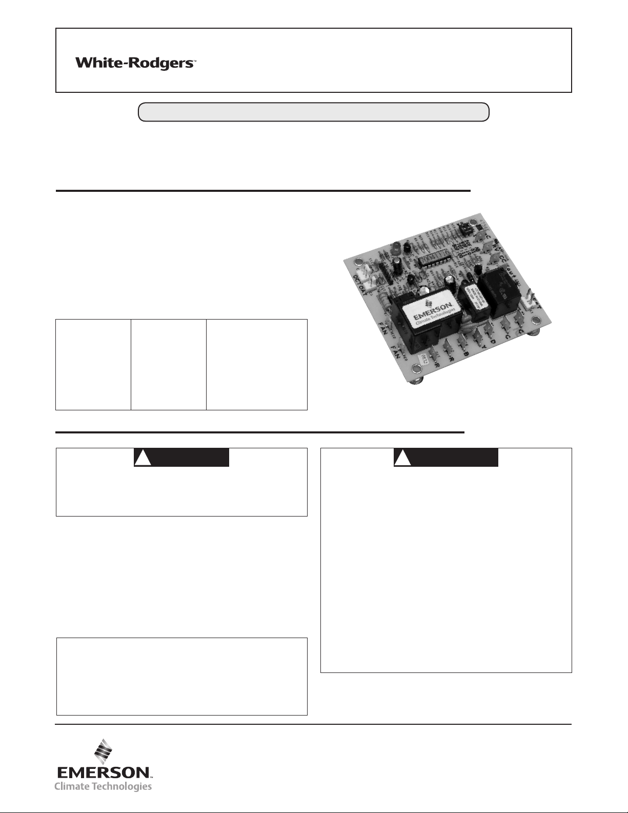
Demand Defrost Control
INSTALLATION INSTRUCTIONS
Operator: Save these instructions for future use!
FAILURE TO READ AND FOLLOW ALL INSTRUCTIONS CAREFULLY BEFORE
INSTALLING OR OPERATING THIS CONTROL COULD CAUSE PERSONAL
INJURY AND/OR PROPERTY DAMAGE.
DESCRIPTION
The 47D40-801 control is a microprocessor-based demand
defrost controller intended for Rheem heat pump systems.
This controller uses basic differential temperature means to
detect degradation of system performance due to ice build-up
on the outdoor coil. The controller uses “self-calibrating” principles to calibrate to the heat pump system. The defrosting is
performed by reversing the refrigerant direction of flow.
The 47D40-801 is meant to replace the following controllers
in Rheem heat pump systems:
47-21517-16
47-21517-17
47-21517-18
47-21517-23
47-21517-24
47-21517-11
47-21517-14
47-21517-13
47-21517-82
47-21517-88
47-102685-01
47-102685-03
47-102684-01
47-102684-03
47-102684-83
DDL-013102-1RH
DDL-017002-2RH
DDL-017102-1RH
DDL-017702-1RH
DDL-117702-3RH
DDL-013002-0RH
DDL-013002-1RH
47D40-801
PRECAUTIONS
CAUTION
• This control is intended only for Rheem heat pump
systems.
• Replace 47D40-801 control as a unit - no user serviceable parts.
If in doubt about whether your wiring is millivolt, line or low
voltage, have it inspected by a qualified heating and air
conditioning contractor or licensed electrician.
Do not exceed the specification ratings.
All wiring must conform to local and national electrical codes
and ordinances.
This control is a precision instrument, and should be handled
carefully. Rough handling or distorting components could
cause the control to malfunction.
CONTENTS
Description ................................................................ 1
Precautions .............................................................. 1
Specifications ........................................................... 2
Operation .................................................................. 2
Installation ................................................................ 3
• To prevent electrical shock and/or equipment damage,
disconnect electric power to system at main fuse or
circuit breaker box until installation is complete.
• This control is not intended for use in locations where
it may come in direct contact with water. Suitable
protections must be provided to shield the control from
exposure to water (dripping, spraying, rain, etc.)
• Label all wires prior to disconnection when servicing
controls. Wiring errors can cause improper or loss of
heat pump operation and/or shock hazard.
• Following installation or replacement, follow appliance
manufacturer’s recommended installation/service
instructions to insure proper operation.
• Do not use on circuits exceeding specied voltage.
Higher voltage will damage control and could cause
shock or re hazard.
!
white-rodgers.com
emersonclimate.com
PART NO. 37-7200B
Replaces 37-7200A
1536
Page 2
SPECIFICATIONS
Electrical Ratings [@ 77o F (25o C)]:
Rated Voltage ..................................... 24 VAC
Rated Voltage Range ............................... 18-30 VAC
Max. Power Consumption @ 24 VAC .................. 4.08 VA
Nominal Frequency................................. 50/60 Hz
Relay Load Ratings:
Compressor Contactor Relay ...................... 20 VA in rush, 6 VA holding
Fan Relay ...................................... 1/2 HP @ 240, 1/4 HP @ 120 VAC
Reversing Valve Relay (RV) ........................ 24 VA
Auxiliary Heat Relay (D)........................... 1 Amp. 0.6 P.F.
Operating Temperature Range ........................ -40o to 150o F (-40o to 65o C)
Humidity Range ................................... 5% to 95% relative humidity
(non-condensing)
Timing Specications @ 60Hz*
Nom Units
Defrost Lockout Time 34 Mins.
Maximum Defrost Time 14 Mins.
Transient Delay 2 Mins.
Maximum Frosting Time 6 Hrs.
Short Cycle Lockout Time 5 Mins.
Noise Abatement Time 5 Sec.
*50Hz Timings are 20% longer.
The control is recognized by UL as an incorporated
electronics control per UL 60730-1A. This control does
not perform any safety/protective functions. This device is
automatic, type 1 action, incorporated control.
OPERATION
Each controller has 24 VAC input and B, Y, and D terminals
for connection to a standard thermostat. The controller has
pins for connection of two temperature sensors to measure
ambient and coil temperature. Controlled outputs are outdoor
fan, reversing valve, and compressor contactor.
The controller has a LED to indicate system operation status.
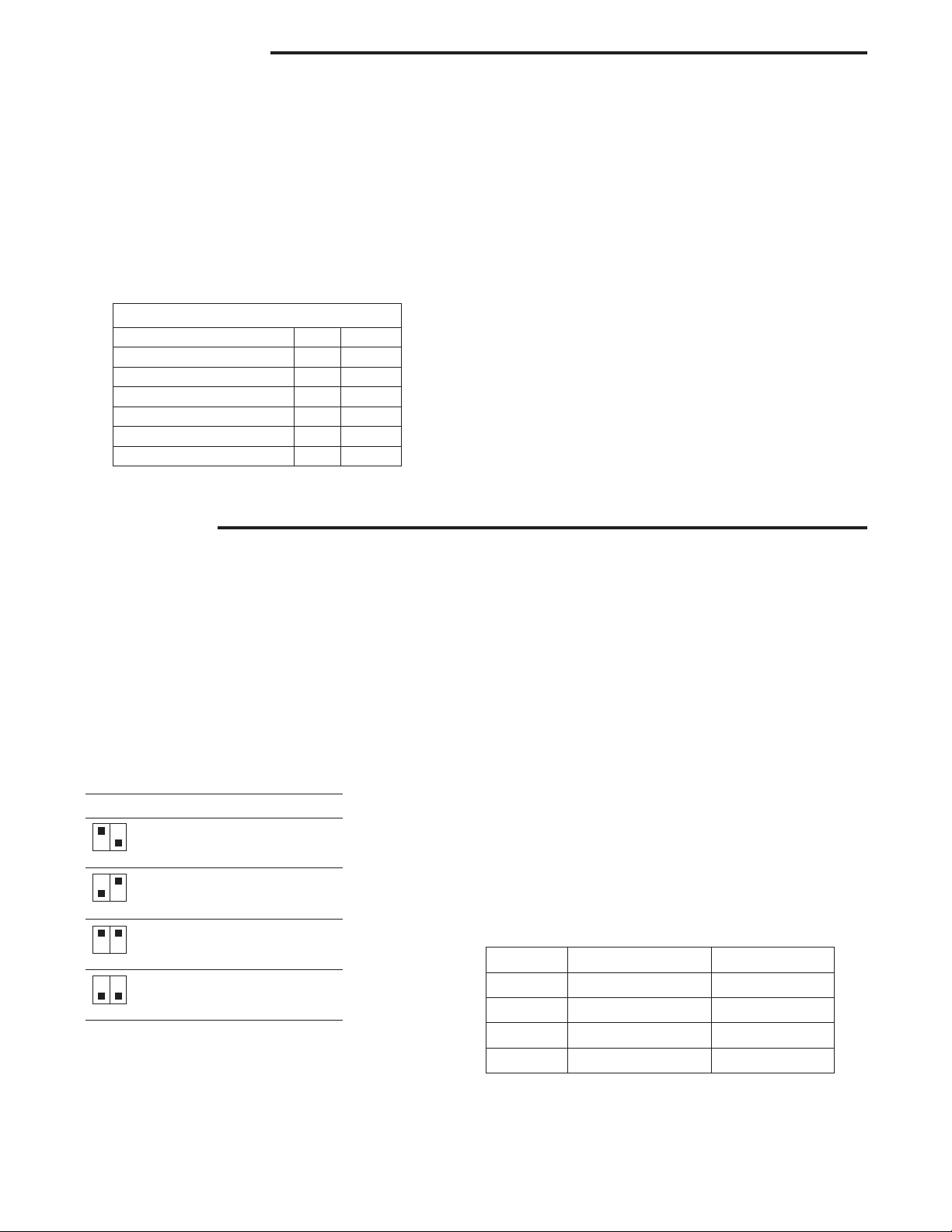
Option Switch
Switch labeled SW1 is used to select the defrost mode
termination temperature of outdoor coil. Defrost mode is
terminated when the coil temperature exceeds the selected
termination temperature. Temperature options for SW1 switch
settings are:
B A
On Off 50o F
B A
Off On 60o F
B A
On On 70o F (default)
B A
Off Off 80o F
B A
Test Pins
The connector labeled TEST can be used to change
operation mode in the field. Momentarily short the test pins
to force the system into the defrost mode. Momentarily short
the test pins again to terminate the defrost mode. To avoid
unnecessary system mode transition, do not use the test pins
frequently.
Short Cycle Protection
The control includes protection against short cycling the
compressor. At power-up, and each time the Y input is
interrupted, the control will enter a 5-minute short cycle
lockout period. During this lockout, the control will not
energize the compressor contactor, even if a call for heating
or cooling is received on the Y input. The control will resume
normal operation when the lockout period expires.
Noise Abatement
When the reversing valve is switched during an active call for
heating or cooling, such as when entering or leaving a defrost
cycle, the control will de-energize the compressor contactor
for 5 seconds in order to reduce compressor noise.
Diagnostic Features
The control continuously monitors system operation. If a fault
occurs, the red LED on the control will flash a diagnostic
code, if more than one fault occurs, only the code with the
higher priority will flash. The flash time is to be 0.5 seconds
on and 0.5 seconds off followed by 2 seconds off. The table
shows the diagnostic codes:
LED Fault Indication Display Priority
ON Normal 0
1 Flash Defrost mode 1
2 Flashes Coil sensor fault 3
3 Flashes Ambient sensor fault 2
2
Page 3

INSTALLATION
NOTE
COMPR
CONTACTO
FAN MOTOR
On some units, the Outdoor Ambient Temperature (OAT) and
Outdoor Coil Temperature (OCT) sensors may be attached
permanently to the controller. The 47D40-801 includes
replacement OAT and OCT sensors that plug onto the 2- and
3-pin connectors on the controller board.
Before removing the old controller, note the location of the
OCT sensor on the outdoor coil. The new sensor should
be attached to the coil in the same location, or as close as
possible. The OAT sensor is typically 24-48” long, although
some controllers have the sensor on the board. Placement of
the OAT sensor is not as critical as the OCT sensor, but both
sensors are required for the controller to operate.
Four metal standoffs are used to support and mount the
control into the unit.
Board size is 3.375 in. x 3.625 in. and requires 1 inch of
headroom (not including mounting).
Typical System Wiring Table
47D40
Terminal Type System Component Connection
C 0.25” QC Reversing valve common
RV 0.25” QC Reversing valve output
CC 0.25” QC Compressor contactor coil
Yout 0.25” QC Compressor call output
C (2) 0.25” QC Common, 24VAC return
D 0.25” QC Defrost output
Y 0.25” QC Compressor call input
B 0.25” QC Heating mode signal input
R (2) 0.25” QC 24VAC input
Fan (2) 0.25” QC Outdoor fan control
OAT 2-pin connector Outdoor ambient temperature sensor
OCT 3-pin connector Outdoor coil temperature sensor
All wiring should be installed according to local and national
electrical codes and ordinances.
The 47D40-801 control may be mounted on any convenient
surface using the four standoffs provided.
The control must be secured to an area that will experience
a minimum of vibration and remain below the maximum
ambient temperature rating of 150o F. The control is approved
for minimum ambient temperatures of -40o F.
Any orientation is acceptable.
Refer to the wiring diagram and wiring table when
connecting the 47D40-801 control to other components of
the system.
UL approved, 105o C rated 18 gauge min., stranded 2/64”
thick insulation wire is recommended for all low voltage safety
circuit connections.
UL approved, 105o C rated 16 gauge min., stranded 2/64”
thick insulation wire is recommended for all line voltage
connections.
Following installation or replacement, follow appliance
manufacturer’s recommended installation or service
instructions to insure proper operation.
Legend
COMPRESSOR
ESSOR
R
REVERSING
VALVE
Low Voltage
Line Voltage
Internal Control
Tracing
HERM FAN
RUN CAPACITOR
TO THERMOSTAT
Y
C
B
CC
RV
S
R
C
L1
L2
D
Yout
CC
RV
C
Demand Defrost Control
Fig 1. Typical System Wiring Diagram
C
OUTDOOR
R
S
C
R
FAN
FAN
OAT
OCT
3
Page 4

White-Rodgers is a business
of Emerson Electric Co.
The Emerson logo is a
trademark and service mark
of Emerson Electric Co.
white-rodgers.com
emersonclimate.com
 Loading...