

Page 1
Reference Manual
00809-0100-2230, Rev BB
August 2014
Rosemount 2230
Graphical Field Display
www.rosemount-tg.com
Page 2

Page 3

Reference Manual
00809-0100-2230, Rev BB
August 2014
Rosemount 2230
Rosemount 2230
Graphical Field Display
NOTICE
Read this manual before working with the product. For personal and system safety, and for
optimum product performance, make sure you thoroughly understand the contents before
installing, using, or maintaining this product.
For equipment service or support needs, contact your local Emerson Process
Management/Rosemount Tank Gauging representative.
Spare Parts
Any substitution of non-recognized spare parts may jeopardize safety. Repair, e.g.
substitution of components etc, may also jeopardize safety and is under no circumstances
allowed.
Rosemount Tank Radar AB will not take any responsibility for faults, accidents, etc caused
by non-recognized spare parts or any repair which is not made by
Rosemount Tank Radar AB.
Cover Photo: 2230_coverphoto_2.jpg
www.rosemount-tg.com
Page 4

Page 5

Reference Manual
00809-0100-2230, Rev BB
August 2014
Rosemount 2230
Table of Contents
SECTION 1
Introduction
SECTION 2
Overview
SECTION 3
Installation
1.1 Safety Messages . . . . . . . . . . . . . . . . . . . . . . . . . . . . . . . . . . . . 1-1
1.2 Symbols. . . . . . . . . . . . . . . . . . . . . . . . . . . . . . . . . . . . . . . . . . . 1-2
1.3 Manual Overview. . . . . . . . . . . . . . . . . . . . . . . . . . . . . . . . . . . . 1-3
1.4 Technical Documentation . . . . . . . . . . . . . . . . . . . . . . . . . . . . . 1-4
1.5 Product Recycling/ Disposal . . . . . . . . . . . . . . . . . . . . . . . . . . . 1-5
1.6 Packing Material . . . . . . . . . . . . . . . . . . . . . . . . . . . . . . . . . . . . 1-5
1.6.1 Reuse and Recycling . . . . . . . . . . . . . . . . . . . . . . . . . 1-5
1.6.2 Energy recovery . . . . . . . . . . . . . . . . . . . . . . . . . . . . . 1-5
2.1 Introduction . . . . . . . . . . . . . . . . . . . . . . . . . . . . . . . . . . . . . . . . 2-1
2.2 2230 Components . . . . . . . . . . . . . . . . . . . . . . . . . . . . . . . . . . . 2-2
2.3 System Overview. . . . . . . . . . . . . . . . . . . . . . . . . . . . . . . . . . . . 2-3
2.3.1 System Start-up . . . . . . . . . . . . . . . . . . . . . . . . . . . . 2-10
2.4 Installation procedure . . . . . . . . . . . . . . . . . . . . . . . . . . . . . . . 2-11
3.1 Safety Messages . . . . . . . . . . . . . . . . . . . . . . . . . . . . . . . . . . . . 3-1
3.2 Mechanical Installation . . . . . . . . . . . . . . . . . . . . . . . . . . . . . . . 3-2
3.2.1 Installation Considerations . . . . . . . . . . . . . . . . . . . . . 3-2
3.2.2 Mounting the Graphical Display . . . . . . . . . . . . . . . . . 3-3
3.3 Electrical Installation . . . . . . . . . . . . . . . . . . . . . . . . . . . . . . . . . 3-6
3.3.1 Cable/Conduit Entries . . . . . . . . . . . . . . . . . . . . . . . . 3-6
3.3.2 Grounding. . . . . . . . . . . . . . . . . . . . . . . . . . . . . . . . . . 3-6
3.3.3 Cable Selection . . . . . . . . . . . . . . . . . . . . . . . . . . . . . 3-7
3.3.4 Hazardous Areas . . . . . . . . . . . . . . . . . . . . . . . . . . . . 3-7
3.3.5 Power Requirements . . . . . . . . . . . . . . . . . . . . . . . . . 3-7
3.3.6 The Tankbus . . . . . . . . . . . . . . . . . . . . . . . . . . . . . . . 3-8
3.3.7 Typical installations . . . . . . . . . . . . . . . . . . . . . . . . . . 3-9
3.3.8 2230 in FOUNDATION fieldbus systems . . . . . . . . . . . 3-10
3.3.9 Wiring . . . . . . . . . . . . . . . . . . . . . . . . . . . . . . . . . . . . 3-11
3.4 LED signals and Reset Button. . . . . . . . . . . . . . . . . . . . . . . . . 3-14
3.5 Switches . . . . . . . . . . . . . . . . . . . . . . . . . . . . . . . . . . . . . . . . . 3-15
3.5.1 DIP Switches . . . . . . . . . . . . . . . . . . . . . . . . . . . . . . 3-15
3.6 Ambient Temperature . . . . . . . . . . . . . . . . . . . . . . . . . . . . . . . 3-16
Table of Contents
TOC-1
Page 6

Rosemount 2230
Reference Manual
00809-0100-2230, Rev BB
August 2014
SECTION 4
Configuration and
Operation
4.1 Safety Messages . . . . . . . . . . . . . . . . . . . . . . . . . . . . . . . . . . . . 4-1
4.2 Introduction . . . . . . . . . . . . . . . . . . . . . . . . . . . . . . . . . . . . . . . . 4-3
4.2.1 The 2230 Graphical Field Display . . . . . . . . . . . . . . . 4-3
4.2.2 Configuration Tools . . . . . . . . . . . . . . . . . . . . . . . . . . 4-4
4.2.3 Activity and Alarm Indication . . . . . . . . . . . . . . . . . . . 4-5
4.2.4 Start-Up Procedure . . . . . . . . . . . . . . . . . . . . . . . . . . 4-6
4.3 Menu Tree . . . . . . . . . . . . . . . . . . . . . . . . . . . . . . . . . . . . . . . . . 4-7
4.4 The Main Menu . . . . . . . . . . . . . . . . . . . . . . . . . . . . . . . . . . . . . 4-8
4.5 The Select View Menu. . . . . . . . . . . . . . . . . . . . . . . . . . . . . . . . 4-9
4.6 The Options Menu . . . . . . . . . . . . . . . . . . . . . . . . . . . . . . . . . . 4-10
4.6.1 Variables . . . . . . . . . . . . . . . . . . . . . . . . . . . . . . . . . 4-11
4.6.2 Select Tanks. . . . . . . . . . . . . . . . . . . . . . . . . . . . . . . 4-13
4.6.3 Units for Display . . . . . . . . . . . . . . . . . . . . . . . . . . . . 4-14
4.6.4 Toggle Time . . . . . . . . . . . . . . . . . . . . . . . . . . . . . . . 4-16
4.6.5 Language . . . . . . . . . . . . . . . . . . . . . . . . . . . . . . . . . 4-16
4.7 The Service Menu . . . . . . . . . . . . . . . . . . . . . . . . . . . . . . . . . . 4-17
4.7.1 Status . . . . . . . . . . . . . . . . . . . . . . . . . . . . . . . . . . . . 4-18
4.7.2 Custody Transfer View . . . . . . . . . . . . . . . . . . . . . . . 4-18
4.7.3 LCD Test . . . . . . . . . . . . . . . . . . . . . . . . . . . . . . . . . 4-19
4.7.4 LCD Contrast . . . . . . . . . . . . . . . . . . . . . . . . . . . . . . 4-19
4.7.5 Restart . . . . . . . . . . . . . . . . . . . . . . . . . . . . . . . . . . . 4-20
4.7.6 Factory Settings . . . . . . . . . . . . . . . . . . . . . . . . . . . . 4-20
4.7.7 About . . . . . . . . . . . . . . . . . . . . . . . . . . . . . . . . . . . . 4-21
4.8 FOUNDATION Fieldbus Overview. . . . . . . . . . . . . . . . . . . . . . . . 4-22
4.8.1 Block Operation . . . . . . . . . . . . . . . . . . . . . . . . . . . . 4-22
4.9 Device Capabilities . . . . . . . . . . . . . . . . . . . . . . . . . . . . . . . . . 4-23
4.9.1 Link Active Scheduler. . . . . . . . . . . . . . . . . . . . . . . . 4-23
4.9.2 Device Addressing . . . . . . . . . . . . . . . . . . . . . . . . . . 4-23
4.9.3 Capabilities. . . . . . . . . . . . . . . . . . . . . . . . . . . . . . . . 4-23
4.10 General Block Information . . . . . . . . . . . . . . . . . . . . . . . . . . . . 4-24
4.10.1 Modes. . . . . . . . . . . . . . . . . . . . . . . . . . . . . . . . . . . . 4-24
4.10.2 Factory Configuration . . . . . . . . . . . . . . . . . . . . . . . . 4-25
4.11 Multiple Analog Output Blocks. . . . . . . . . . . . . . . . . . . . . . . . . 4-25
4.11.1 Configure the MAO Blocks . . . . . . . . . . . . . . . . . . . . 4-25
4.11.2 Application Example. . . . . . . . . . . . . . . . . . . . . . . . . 4-26
4.12 Resource Block . . . . . . . . . . . . . . . . . . . . . . . . . . . . . . . . . . . . 4-27
4.12.1 FEATURES and FEATURES_SEL . . . . . . . . . . . . . 4-27
4.12.2 MAX_NOTIFY . . . . . . . . . . . . . . . . . . . . . . . . . . . . . 4-28
4.12.3 Field Diagnostic Alerts . . . . . . . . . . . . . . . . . . . . . . . 4-29
4.12.4 Recommended Actions for Alerts. . . . . . . . . . . . . . . 4-32
4.12.5 Alarm Priority . . . . . . . . . . . . . . . . . . . . . . . . . . . . . . 4-32
4.13 475 Field Communicator Menu Tree . . . . . . . . . . . . . . . . . . . . 4-33
4.14 Configuration Using AMS Device Manager . . . . . . . . . . . . . . . 4-34
4.14.1 Starting the Guided Setup . . . . . . . . . . . . . . . . . . . . 4-34
4.14.2 Manual Setup . . . . . . . . . . . . . . . . . . . . . . . . . . . . . . 4-39
4.15 Alert Setup. . . . . . . . . . . . . . . . . . . . . . . . . . . . . . . . . . . . . . . . 4-40
4.15.1 Alert Default Settings . . . . . . . . . . . . . . . . . . . . . . . . 4-42
TOC-2
Table of Contents
Page 7

Reference Manual
00809-0100-2230, Rev BB
August 2014
Rosemount 2230
SECTION 5
Service and
Troubleshooting
5.1 Safety Messages . . . . . . . . . . . . . . . . . . . . . . . . . . . . . . . . . . . . 5-1
5.2 Service. . . . . . . . . . . . . . . . . . . . . . . . . . . . . . . . . . . . . . . . . . . . 5-2
5.2.1 Status Information . . . . . . . . . . . . . . . . . . . . . . . . . . . 5-2
5.2.2 Viewing Input and Holding Registers . . . . . . . . . . . . . 5-3
5.2.3 Restarting the 2230 Display . . . . . . . . . . . . . . . . . . . . 5-5
5.2.4 Device Error Signals. . . . . . . . . . . . . . . . . . . . . . . . . . 5-6
5.3 Troubleshooting. . . . . . . . . . . . . . . . . . . . . . . . . . . . . . . . . . . . . 5-7
5.3.1 General. . . . . . . . . . . . . . . . . . . . . . . . . . . . . . . . . . . . 5-7
5.3.2 Tankbus System. . . . . . . . . . . . . . . . . . . . . . . . . . . . . 5-8
5.3.3 Foundation Fieldbus System . . . . . . . . . . . . . . . . . . . 5-9
5.3.4 Device Errors . . . . . . . . . . . . . . . . . . . . . . . . . . . . . . 5-10
5.3.5 Device Warnings . . . . . . . . . . . . . . . . . . . . . . . . . . . 5-11
5.3.6 Status Information . . . . . . . . . . . . . . . . . . . . . . . . . . 5-12
5.4 Resource Block . . . . . . . . . . . . . . . . . . . . . . . . . . . . . . . . . . . . 5-13
5.5 Transducer Block. . . . . . . . . . . . . . . . . . . . . . . . . . . . . . . . . . . 5-13
5.6 Alerts . . . . . . . . . . . . . . . . . . . . . . . . . . . . . . . . . . . . . . . . . . . . 5-14
5.6.1 Viewing Active Alerts in AMS . . . . . . . . . . . . . . . . . . 5-14
5.6.2 Recommended Actions . . . . . . . . . . . . . . . . . . . . . . 5-16
5.7 Service Tools In AMS . . . . . . . . . . . . . . . . . . . . . . . . . . . . . . . 5-17
5.7.1 Service Tools Window . . . . . . . . . . . . . . . . . . . . . . . 5-17
5.7.2 Device Status . . . . . . . . . . . . . . . . . . . . . . . . . . . . . . 5-19
5.7.3 Viewing Input/Holding Registers . . . . . . . . . . . . . . . 5-20
5.7.4 Reset/Restore . . . . . . . . . . . . . . . . . . . . . . . . . . . . . 5-22
5.7.5 Variables . . . . . . . . . . . . . . . . . . . . . . . . . . . . . . . . . 5-23
5.7.6 Simulation. . . . . . . . . . . . . . . . . . . . . . . . . . . . . . . . . 5-24
5.7.7 Active Alerts . . . . . . . . . . . . . . . . . . . . . . . . . . . . . . . 5-24
5.8 Write Protection . . . . . . . . . . . . . . . . . . . . . . . . . . . . . . . . . . . . 5-25
APPENDIX A
Reference Data
APPENDIX B
Product Certifications
APPENDIX C
OUNDATION fieldbus
F
Block Information
A.1 Specifications . . . . . . . . . . . . . . . . . . . . . . . . . . . . . . . . . . . . . .A-1
A.2 Dimensional drawings . . . . . . . . . . . . . . . . . . . . . . . . . . . . . . . .A-3
A.3 Ordering Information . . . . . . . . . . . . . . . . . . . . . . . . . . . . . . . . . A-4
B.1 Safety messages . . . . . . . . . . . . . . . . . . . . . . . . . . . . . . . . . . . .B-1
B.2 EU Conformity . . . . . . . . . . . . . . . . . . . . . . . . . . . . . . . . . . . . . . B-2
B.3 Hazardous Locations Certifications . . . . . . . . . . . . . . . . . . . . . .B-3
B.3.1 Factory Mutual US Approvals. . . . . . . . . . . . . . . . . . .B-3
B.3.2 Factory Mutual Canadian Approvals . . . . . . . . . . . . . B-4
B.3.3 European ATEX Directive Information . . . . . . . . . . . .B-5
B.3.4 IECEx Approval . . . . . . . . . . . . . . . . . . . . . . . . . . . . .B-7
B.4 Approval Drawings . . . . . . . . . . . . . . . . . . . . . . . . . . . . . . . . . .B-8
C.1 Resource Block . . . . . . . . . . . . . . . . . . . . . . . . . . . . . . . . . . . . .C-2
C.2 Register Transducer Block . . . . . . . . . . . . . . . . . . . . . . . . . . . .C-6
C.3 Main Transducer Block . . . . . . . . . . . . . . . . . . . . . . . . . . . . . . .C-8
C.3.1 Diagnostic Device Alerts . . . . . . . . . . . . . . . . . . . . . .C-9
C.4 Display Transducer Block . . . . . . . . . . . . . . . . . . . . . . . . . . . .C-10
C.5 Multiple Analog Output Block . . . . . . . . . . . . . . . . . . . . . . . . .C-13
C.6 Supported Units. . . . . . . . . . . . . . . . . . . . . . . . . . . . . . . . . . . .C-15
Table of Contents
TOC-3
Page 8

Rosemount 2230
Reference Manual
00809-0100-2230, Rev BB
August 2014
TOC-4
Table of Contents
Page 9
Reference Manual
00809-0100-2230, Rev BB
August 2014
Section 1 Introduction
1.1 Safety Messages . . . . . . . . . . . . . . . . . . . . . . . . . . . . page 1-1
1.2 Symbols . . . . . . . . . . . . . . . . . . . . . . . . . . . . . . . . . . . page 1-2
1.3 Manual Overview . . . . . . . . . . . . . . . . . . . . . . . . . . . page 1-3
1.4 Technical Documentation . . . . . . . . . . . . . . . . . . . . page 1-4
1.5 Product Recycling/ Disposal . . . . . . . . . . . . . . . . . . page 1-5
1.6 Packing Material . . . . . . . . . . . . . . . . . . . . . . . . . . . . page 1-5
Rosemount 2230
1.1 SAFETY MESSAGES
Procedures and instructions in this manual may require special precautions to
ensure the safety of the personnel performing the operations. Information that
raises potential safety issues is indicated by a warning symbol ( ). Refer to
the safety messages listed at the beginning of each section before performing
an operation preceded by this symbol.
Failure to follow these installation guidelines could result in death or serious
injury:
• Make sure only qualified personnel perform the installation.
• Use the equipment only as specified in this manual. Failure to do so may
impair the protection provided by the equipment.
Explosions could result in death or serious injury:
• Verify that the operating environment of the transmitter is consistent with the
appropriate hazardous locations certifications.
• Before connecting a hand held communicator in an explosive atmosphere,
make sure the instruments in the loop are installed in accordance with
intrinsically safe or non-incendive field wiring practices.
• Do not remove the cover in explosive atmospheres when the circuit is alive.
• Substitution of components may impair Intrinsic Safety.
• To prevent ignition of flammable or combustible atmospheres, disconnect
power before servicing.
Electrical shock could cause death or serious injury.
• Use extreme caution when making contact with the leads and terminals.
www.rosemount-tg.com
Any substitution of non-recognized parts may jeopardize safety. Repair, e.g. substitution
of components etc., may also jeopardize safety and is under no circumstances allowed.
Page 10

Rosemount 2230
1.2 SYMBOLS
Reference Manual
00809-0100-2230, Rev BB
August 2014
The CE marking symbolizes the conformity
of the product with the applicable European
Community Directives.
The EC-Type Examination Certificate is a
statement of a Notified Certification Body
declaring that this product meets the
Essential Health and Safety Requirements
of the ATEX directive.
The FM APPROVED Mark indicates that the
equipment is approved by FM Approvals
according to applicable Approval Standards
and is applicable for installation in
hazardous locations.
Protective Earth.
Ground.
External cabling must be approved for use in
min. 75°C.
1-2
Section 1. Introduction
Page 11

Reference Manual
00809-0100-2230, Rev BB
August 2014
Rosemount 2230
1.3 MANUAL OVERVIEW
Section 1:Introduction
• Manual overview
• Product recycling/disposal
• Packing material
Section 2: Overview
• Introduction
• 2230 Components
• System Overview
• Getting started
• Installation Procedure
Section 3: Installation
• Mounting considerations
• Mechanical installation
• Electrical installation
• LED signals and Reset button
• Switches
Section 4: Configuration
• Menu tree
• Select View menu
• Options menu
• Service menu
• Foundation fieldbus information
Section 5: Service and troubleshooting
• Service
• Troubleshooting
Appendix A: Reference data
• Specifications
• Dimensional Drawings
• Ordering Information
Appendix B: Product certifications
• EU Conformity
• FM US Approvals
• FM Canadian Approvals
• European ATEX Directive Information
• IECEx Approval
Appendix C: Foundation Fieldbus Block Information
• Block parameters
• Supported units
Section 1. Introduction
1-3
Page 12

Rosemount 2230
Reference Manual
00809-0100-2230, Rev BB
August 2014
1.4 TECHNICAL DOCUMENTATION
The Rosemount Tank Gauging System includes the following documents:
Document Reference Number
Rosemount Raptor System Data Sheet 704010EN
Rosemount 5900S Reference Manual 00809-0100-5900
Rosemount 2410 Reference Manual 300530EN
Rosemount 2240S Reference Manual 00809-0100-2240
Rosemount 2230 Reference Manual 00809-0100-2230
Rosemount Raptor System Configuration Manual 300510EN
Rosemount Raptor Wireless Tank Gauging System
Reference Manual
Rosemount 5300 Product Data Sheet 00813-0100-4530
Rosemount 5400 Product Data Sheet 00813-0100-4026
Rosemount 5300 Series Reference Manual 00809-0100-4530
Rosemount 5400 Series Reference Manual 00809-0100-4026
Rosemount TankMaster WinOpi Reference Manual 303028EN
Rosemount Raptor Installation Drawings
300570EN
1-4
Section 1. Introduction
Page 13

Reference Manual
00809-0100-2230, Rev BB
August 2014
Rosemount 2230
1.5 PRODUCT RECYCLING/ DISPOSAL
Figure 1-1. A green label is
placed on the housing
1.6 PACKING MATERIAL
1.6.1 Reuse and
Recycling
Recycling of equipment and packaging should be taken into consideration
and disposed of in accordance with local and national legislation/regulations.
The label below is put on Rosemount Tank Gauging products as a
recommendation to customers if scrapping is considered.
Recycling or disposal should be done following instructions for correct
separation of materials when breaking up the units.
R
A
A
T
P
E
E
S
S
T
E
E
L
&
Rosemount Tank Radar AB is fully certified according to ISO 14001
environmental standards. By recycling the corrugated paperboard, or wooden
boxes, used for shipping our products you can contribute to take care of the
environment.
Experience has shown that wooden boxes can be used several times for
various purposes. After careful disassembly the wooden parts may be reused.
Metal waste may be converted.
C
I
T
S
A
L
P
1.6.2 Energy recovery Products which have served their time may be divided into wood and metal
components and the wood can be used as fuel in sufficient ovens.
Due to its low moisture content (approximately 7%) this fuel has a higher
calorific value than ordinary wood fuel (moisture content approximately 20%).
When burning interior plywood the nitrogen in the adhesives may increase
emissions of nitrogen oxides to the air 3-4 times more than when burning bark
and splinter.
NOTE!
Landfill is not a recycling option and should be avoided.
Section 1. Introduction
1-5
Page 14

Rosemount 2230
Reference Manual
00809-0100-2230, Rev BB
August 2014
1-6
Section 1. Introduction
Page 15
Reference Manual
00809-0100-2230, Rev BB
August 2014
Rosemount 2230
Section 2 Overview
2.1 Introduction . . . . . . . . . . . . . . . . . . . . . . . . . . . . . . . . page 2-1
2.2 2230 Components . . . . . . . . . . . . . . . . . . . . . . . . . . . page 2-2
2.3 System Overview . . . . . . . . . . . . . . . . . . . . . . . . . . .page 2-3
2.4 Installation procedure . . . . . . . . . . . . . . . . . . . . . . . page 2-11
2.1 INTRODUCTION The Rosemount 2230 Graphical Field Display presents inventory tank
gauging data such as level, temperature, and pressure. The 2230 Display
communicates with the Rosemount 2410 Tank Hub via the intrinsically safe
2-wire Tankbus
systems.
A 2230 connected to the multiple tank version of the 2410 Tank Hub allows
you to view data from several tanks. It is possible to configure presentation of
measurement variables for each tank individually.
The four softkeys at the front of the 2230 allow you to navigate through the
different menus and provides all tank data, directly on the field.
(1)
. The 2230 also supports installation in Foundation fieldbus
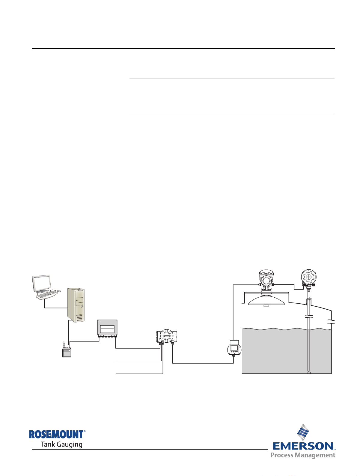
Figure 2-1. System integration
TankMaster
2160 Field
Communication Unit
Group Bus
Modem
Data from a group of tanks is buffered by a 2160 Field Communication Unit
(FCU), and is distributed via the Group Bus to a TankMaster PC, or a host
system, whenever the FCU receives a request for data. In case no FCU is
included in the system, the 2410 Tank Hub can communicate directly with the
host computer.
2240S Temperature
Transmitter
2410 Tank Hub
Primary Bus
Secondary bus
Relay outputs
5900S Radar
Level Gauge
2230 Display
Tankbus
www.rosemount-tg.com
(1) The intrinsically safe Tankbus complies with the FISCO FOUNDATION™ fieldbus standard.
See reference document IEC/TS 60079-27.
Page 16
Rosemount 2230
2.2 2230 COMPONENTS
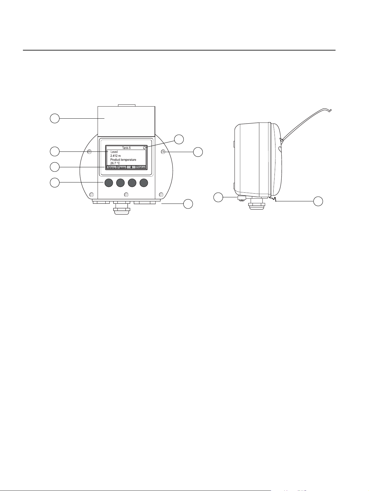
Figure 2-2. Rosemount 2230
components
1
Reference Manual
00809-0100-2230, Rev BB
August 2014
5
2
3
4
1. Weather protection lid
6
8
7
(1)
9
2. Display
3. Menu
4. Soft keys
5. Activity indicator
6. Cover screw
7. Cable entries: two M20 x 1.5 and one M25 x 1.5
(optional: ½ - 14 NPT and ¾ - 14 NPT adapters)
8. Ground screw
9. Locking spring for weather protection
2-2
(1) It is recommended that the lid is closed whenever possible to protect the LCD from exposure
by ultraviolet radiation from the sun.
Section 2. Overview
Page 17

Reference Manual
00809-0100-2230, Rev BB
August 2014
Rosemount 2230
2.3 SYSTEM OVERVIEW
The Rosemount Tank Gauging state-of-the art inventory and custody transfer
radar tank level gauging system is developed for a wide range of applications
at refineries, tank farms and fuel depots, and fulfills the highest requirements
on performance and safety.
The field devices on the tank communicate over the intrinsically safe
Tankbus. The Tankbus is based on a standardized fieldbus, the FISCO
FOUNDATION™ fieldbus, and allows integration of any device supporting that
protocol. By utilizing a bus powered 2-wire intrinsically safe fieldbus the power
consumption is minimized. The standardized fieldbus also enables integration
of other vendors’ equipment on the tank.
The Rosemount Tank Gauging product portfolio includes a wide range of
components to build small or large customized tank gauging systems. The
system includes various devices, such as radar level gauges, temperature
transmitters, and pressure transmitters for complete inventory control. Such
systems are easily expanded thanks to the modular design.
The versatile Rosemount Tank Gauging system is compatible with, and can
emulate, all major tank gauging systems. Moreover, the well-proven
emulation capability enables step-by-step modernization of a tank farm, from
level gauges to control room solutions.
It is possible to replace old mechanical or servo gauges with modern
Rosemount Tank Gauging gauges, without replacing the control system or
field cabling. It is further possible to replace old HMI/SCADA-systems and
field communication devices without replacing the old gauges.
(1)
There is a distributed intelligence in the various system units which
continuously collect and process measurement data and status information.
When a request for information is received an immediate response is sent
with updated information.
The flexible Rosemount Tank Gauging system supports several combinations
to achieve redundancy, from control room to the different field devices.
Redundant network configuration can be achieved at all levels by doubling
each unit and using multiple control room work stations.
Section 2. Overview
(1) See documents IEC 61158-2 and IEC/TS 60079-27
2-3
Page 18
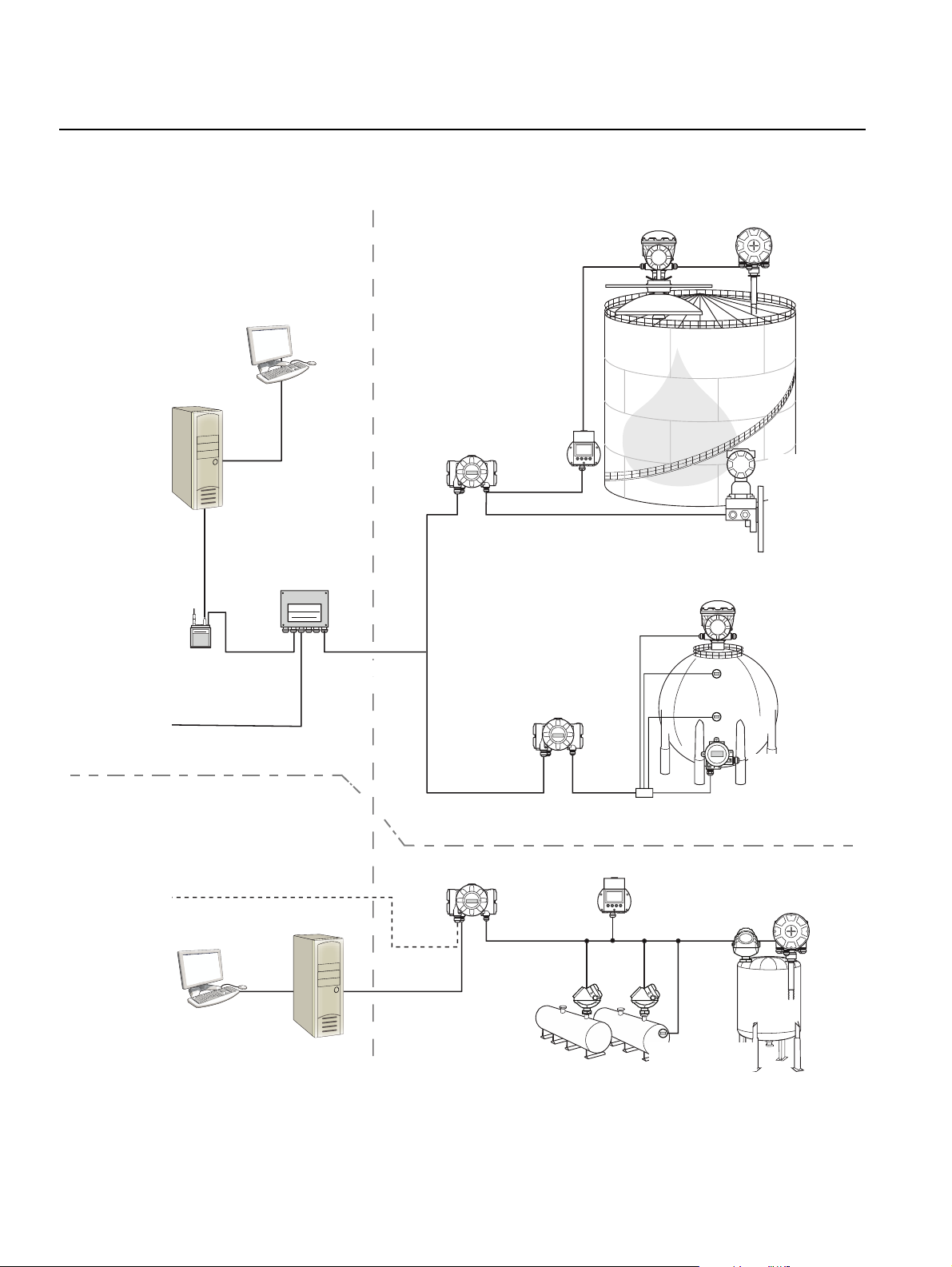
Rosemount 2230
Figure 2-3. Rosemount Tank
Gauging System architecture
NON-HAZARDOUS AREA HAZARDOUS AREA
TankMaster PC
2230 Display
2410 Tank Hub
Tankbus
00809-0100-2230, Rev BB
5900S Radar
Level Gauge
Reference Manual
August 2014
2240S Temperature
Transmitter
3051S
Pressure
Transmitter
2160 Field
2180 Field
Bus Modem
Plant Host Computer
Communication Unit
Group bus
CUSTODY TRANSFER / INVENTORY TANK GAUGINGOPERATIONAL CONTROL
Plant Host Computer
TankMaster PC
TRL2 Modbus
2410 Tank Hub
2410 Tank Hub
Tankbus
5300 Level
Transmitter
5900S Radar
Level Gauge
Segment splitter
2230 Display
5400 Level
Transmitter
644 Temperature
Transmitter
644
644
644Temperature
Transmitter
2240S Temperature
Transmitter
2-4
Section 2. Overview
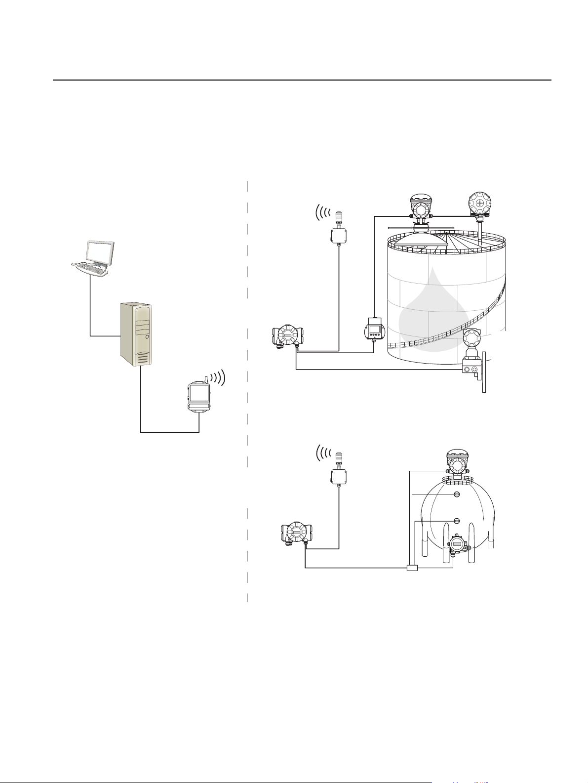
Page 19
Reference Manual
00809-0100-2230, Rev BB
August 2014
Figure 2-4. Rosemount Tank
Gauging system architecture for
wireless systems
NON-HAZARDOUS AREA HAZARDOUS AREA
Rosemount 2230
TankMaster PC
Smart Wireless
Gateway
2410 Tank Hub
Tankbus
THUM
2230
Display
THUM
5900S Radar
Level Gauge
2240S Temperature
Transmitter
3051S
Pressure
Transmitter
5900S Radar
Level Gauge
Section 2. Overview
2410 Tank Hub
644
644
644Temperature
Transmitter
Segment coupler
2-5
Page 20
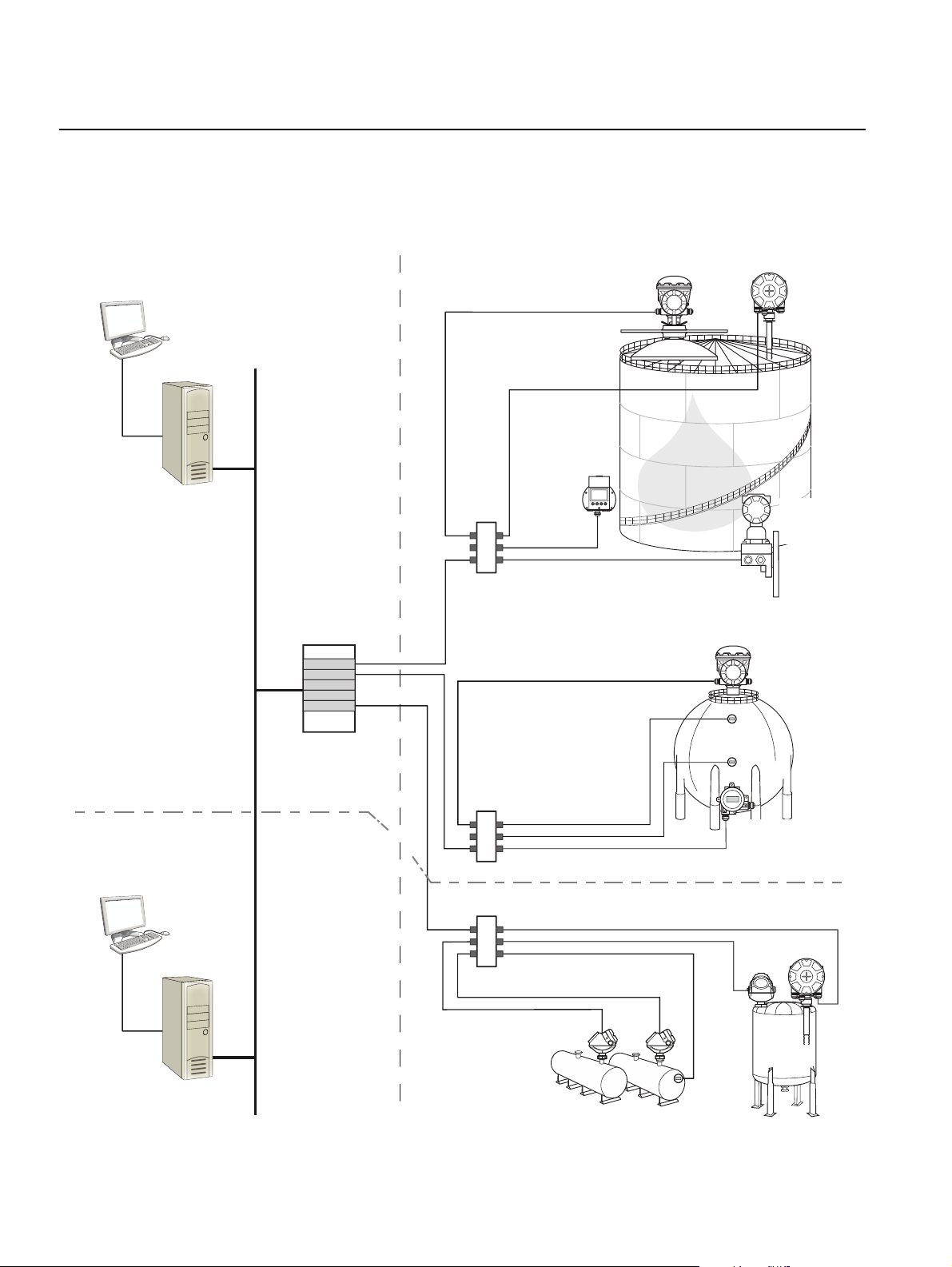
Rosemount 2230
Figure 2-5. Rosemount Tank
Gauging system architecture in
a Foundation fieldbus network
Reference Manual
00809-0100-2230, Rev BB
August 2014
NON-HAZARDOUS AREA HAZARDOUS AREA
2230
Display
FOUNDTION Fieldbus
Power Supply
5900S Radar
Level Gauge
2240S Temperature
Transmitter
3051S
Pressure
Transmitter
5900S Radar
Level Gauge
CUSTODY TRANSFER
INVENTORY TANK GAUGING
PC
OPERATIONAL CONTROL
644
644
Segment coupler
644Temperature
Transmitter
Segment coupler
2-6
Section 2. Overview
Page 21

Reference Manual
00809-0100-2230, Rev BB
August 2014
Rosemount 2230
TankMaster HMI Software
TankMaster is a powerful Windows-based Human Machine Interface (HMI)
for complete tank inventory management. It provides configuration, service,
set-up, inventory, and custody transfer functions for Rosemount Tank
Gauging systems and other supported instruments.
TankMaster is designed to be used in the Microsoft Windows XP and Vista
environment providing easy access to measurement data from your Local
Area Network.
The TankMaster WinOpi program lets the operator monitor measured tank
data. It includes alarm handling, batch reports, automatic report handling,
historical data sampling as well as inventory calculations such as Volume,
Observed Density and other parameters. A plant host computer can be
connected for further processing of data.
The TankMaster WinSetup program is a graphical user interface for
installation, configuration and service of the different devices in the
Rosemount Tank Gauging system.
Rosemount 2160 Field Communication Unit
The 2160 Field Communication Unit (FCU) is a data concentrator that
continuously polls and stores data from field devices such as radar level
gauges and temperature transmitters in a buffer memory. Whenever a request
for data is received, the FCU can immediately send data from a group of
tanks from the updated buffer memory.
Rosemount 2410 Tank Hub
The Rosemount 2410 Tank Hub acts as a power supply to the connected field
devices in the hazardous area using the intrinsically safe Tankbus.
The 2410 collects measurement data and status information from field
devices on a tank. It has two external buses for communication with various
host systems.
There are two versions of the 2410 for single tank or multiple tanks operation.
The 2410 multiple tanks version supports up to 10 tanks and 16 devices. With
the Rosemount 5300 and 5400 level transmitters the 2410 supports up to 5
tanks.
The 2410 is equipped with two relays which support configuration of up to 10
“virtual” relay functions allowing you to specify several source signals for each
relay.
The 2410 supports Intrinsically Safe (IS) and Non-Intrinsically Safe (Non-IS)
analog 4-20 mA inputs/outputs. By connecting a Smart Wireless THUM
Adapter to the IS HART 4-20 mA output, the 2410 is capable of wireless
communication with a Smart Wireless Gateway in a WirelessHART network.
Section 2. Overview
Rosemount 5900S Radar Level Gauge
The Rosemount 5900S Radar Level Gauge is an intelligent instrument for
measuring the product level inside a tank. Different antennas can be used in
order to meet the requirements of different applications. The 5900S can
measure the level of almost any product, including bitumen, crude oil, refined
products, aggressive chemicals, LPG and LNG.
2-7
Page 22

Rosemount 2230
Reference Manual
00809-0100-2230, Rev BB
August 2014
The Rosemount 5900S sends microwaves towards the surface of the product
in the tank. The level is calculated based on the echo from the surface. No
part of the 5900S is in actual contact with the product in the tank, and the
antenna is the only part of the gauge that is exposed to the tank atmosphere.
The 2-in-1 version of the 5900S Radar Level Gauge has two radar modules in
the same transmitter housing allowing two independent level measurements
using one antenna.
Rosemount 5300 Guided Wave Radar
The Rosemount 5300 is a premium 2-wire guided wave radar for level
measurements on liquids, to be used in a wide range of medium accuracy
applications under various tank conditions. Rosemount 5300 includes the
5301 for liquid level measurements and the 5302 for liquid level and interface
measurements.
Rosemount 5400 Radar Level Transmitter
The Rosemount 5400 is a reliable 2-wire non-contact radar level transmitter
for liquids, to be used in a wide range of medium accuracy applications under
various tank conditions.
Rosemount 2240S Multi-Input Temperature Transmitter
The Rosemount 2240S Multi-input Temperature Transmitter can connect up
to 16 temperature spot sensors and an integrated water level sensor.
Rosemount 2230 Graphical Field Display
The Rosemount 2230 Graphical Field Display presents inventory tank
gauging data such as level, temperature, and pressure. The four softkeys
allow you to navigate through the different menus to provide all tank data,
directly in the field. The Rosemount 2230 supports up to 10 tanks. Up to three
displays can be configured by using the TankMaster WinSetup configuration
software.
Rosemount 644 Temperature Transmitter
The Rosemount 644 is used with single spot temperature sensors.
Rosemount 3051S Pressure Transmitter
The 3051S series consists of transmitters and flanges suitable for all kinds of
applications, including crude oil tanks, pressurized tanks and tanks with /
without floating roofs.
By using a 3051S Pressure Transmitter near the bottom of the tank as a
complement to a 5900S Radar Level Gauge, the density of the product can be
calculated and presented. One or more pressure transmitters with different
scalings can be used on the same tank to measure vapor and liquid pressure
2-8
Rosemount 2180 Field Bus Modem
The Rosemount 2180 field bus modem (FBM) is used for connecting a
TankMaster PC to the TRL2 communication bus. The 2180 is connected to
the PC using either the RS232 or the USB interface.
Section 2. Overview
Page 23

Reference Manual
00809-0100-2230, Rev BB
August 2014
Rosemount 2230
Rosemount Smart Wireless Gateway and Rosemount Smart Wireless
THUM Adapter
A THUM Adapter allows wireless communication between a 2410 Tank Hub
and a Smart Wireless Gateway. The gateway is the network manager that
provides an interface between field devices and the TankMaster inventory
software or host / DCS systems.
See the Raptor System Data Sheet (Document no. 704010en) for more
information on the various devices and options.
Section 2. Overview
2-9
Page 24

Reference Manual
Rosemount 2230
00809-0100-2230, Rev BB
August 2014
2.3.1 System Start-up The standard start-up procedure of a Rosemount Tank Gauging system that
includes devices such as the 2160 Field Communication Unit, 2410 Tank
Hub, 5900S Radar Level Gauge, and the 2240S Multi-input Temperature
Transmitter can be summarized as follows:
1. Install the devices on the appropriate locations.
2. Assign Modbus addresses
gauges such as the 5900S Radar Level Gauge, and for auxiliary tank
devices (ATD) such as the 2240S Multi-input Temperature Transmitter.
The Modbus addresses will be stored in the built-in databases of the
Rosemount 2410 Tank Hub and the Rosemount 2160 Field
Communication Unit.
3. Verify that the total current consumption of devices connected to the
Tankbus does not exceed 250 mA
maximum current is 200 mA.
4. Wire the devices.
• Connect field devices to the Tankbus.
Note! Devices must be configured in the tank database
Rosemount 2410 Tank Hub in order to be able to communicate on the
Tankbus.
• Connect the Rosemount 2410 Tank Hub to the Rosemount 2160 Field
Communication Unit.
• Connect the Rosemount 2160 Field Communication Unit to the control
room PC with TankMaster software. The 2160 may be connected via a
Rosemount 2180 Field Bus Modem, or directly via RS 232 or RS 485.
5. Install the TankMaster software in the control room PC.
6. Configure the devices by using the TankMaster WinSetup configuration
tool as described in the Rosemount Raptor System Configuration
Manual (Document no. 300510EN).
(1)
for the Rosemount 2410 Tank Hub, for level
(2)
. In a Smart Wireless System the
(1)(2)
of the
2-10
FOUNDATION Fieldbus
To start up Rosemount Tank Gauging devices in a FOUNDATION fieldbus
system:
1. Prepare the start-up by recording information that will be needed for
configuration of various field devices as described in the Rosemount
Raptor System Configuration manual. This may for example include tank
geometry, antenna type, number of temperature elements and other
configuration parameters.
2. Connect the field devices, such as the Rosemount 5900S Radar Level
Gauge and the Rosemount 2240S Multi-input Temperature Transmitter,
to the FOUNDATION fieldbus network.
3. Configure the field devices by using the AMS Device Manager.
See the Reference Manual for the respective field device and the Rosemount
Raptor System Configuration manual (Document No. 300510) for more
information on how to configure various Raptor devices. See section
“Technical Documentation” on page 1-4 for a list of available documentation.
(1) See the Rosemount Raptor System Configuration Manual (Document no. 300510) for more
information
(2) See the Rosemount 2410 Tank Hub Reference Manual, Document No. 300530 for more
information
Section 2. Overview
Page 25
Reference Manual
00809-0100-2230, Rev BB
August 2014
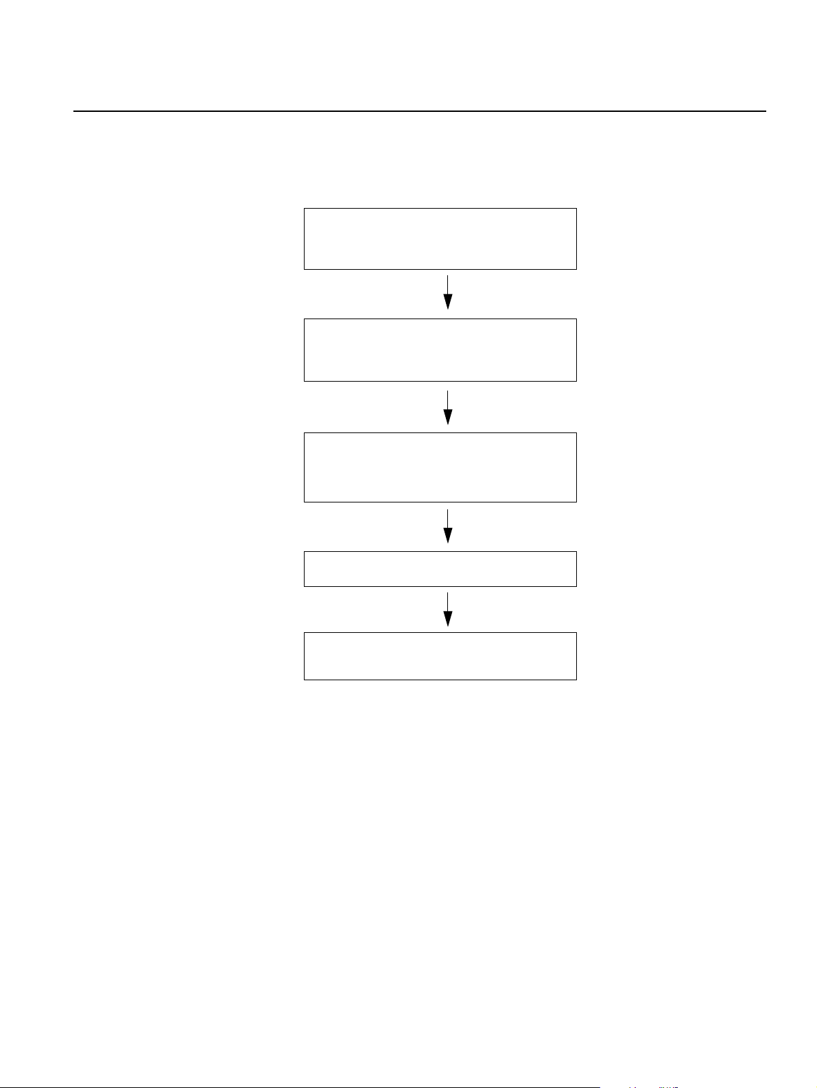
Rosemount 2230
2.4 INSTALLATION PROCEDURE
Follow these steps for proper installation of the Rosemount 2230 Graphical
Field Display:
1. Review installation considerations
(“Installation Considerations” on page 3-2)
2. Mount the 2230 in a suitable location
(“Mounting the Graphical Display” on
page 3-3)
3. Wire the 2230
(“Electrical Installation” on page 3-6)
4. Power up the 2230
5. Configure the 2230
(Section 4: Configuration and Operation)
Section 2. Overview
2-11
Page 26

Rosemount 2230
Reference Manual
00809-0100-2230, Rev BB
August 2014
2-12
Section 2. Overview
Page 27
Reference Manual
00809-0100-2230, Rev BB
August 2014
Section 3 Installation
3.1 Safety Messages . . . . . . . . . . . . . . . . . . . . . . . . . . . . page 3-1
3.2 Mechanical Installation . . . . . . . . . . . . . . . . . . . . . . page 3-2
3.3 Electrical Installation . . . . . . . . . . . . . . . . . . . . . . . . page 3-6
3.4 LED signals and Reset Button . . . . . . . . . . . . . . . . page 3-14
3.5 Switches . . . . . . . . . . . . . . . . . . . . . . . . . . . . . . . . . . page 3-15
3.6 Ambient Temperature . . . . . . . . . . . . . . . . . . . . . . . .page 3-16
Rosemount 2230
3.1 SAFETY MESSAGES
Procedures and instructions in this section may require special precautions to
ensure the safety of the personnel performing the operations. Information that
raises potential safety issues is indicated by a warning symbol ( ). Please
refer to the following safety messages before performing an operation
preceded by this symbol.
Failure to follow safe installation and servicing guidelines could result in death or
serious injury:
Make sure only qualified personnel perform the installation.
Use the equipment only as specified in this manual. Failure to do so may impair the
protection provided by the equipment.
Do not perform any service other than those contained in this manual unless you are
qualified.
Substitution of components may impair Intrinsic Safety.
To prevent ignition of flammable or combustible atmospheres, disconnect power before
servicing.
Explosions could result in death or serious injury:
Verify that the operating environment of the display is consistent with the appropriate
hazardous locations certifications.
Before connecting a hand held communicator in an explosive atmosphere, make sure
the instruments in the loop are installed in accordance with intrinsically safe or
non-incendive field wiring practices.
Do not remove the device cover in explosive atmospheres when the circuit is alive.
www.rosemount-tg.com
High voltage that may be present on leads could cause electrical shock:
Avoid contact with leads and terminals.
Make sure the main power to the Tank Hub is off and the lines to any other external
power source are disconnected or not powered while wiring the device.
Page 28

Rosemount 2230
3.2 MECHANICAL INSTALLATION
Reference Manual
00809-0100-2230, Rev BB
August 2014
3.2.1 Installation
Considerations
Figure 3-1. Space required for
opening the lid
The Rosemount 2230 Graphical Field Display can be installed either on the
tank roof or at the foot of the tank for a flexible and convenient read-out of
tank data.
The 2230 is designed for mounting on a plate, on a wall, or on a pipe. The
display is attached to the plate with four M4 screws. It is important to provide
space for opening the weather protection lid which prevents degradation of
the LCD display due to sunlight exposure.
Consider the following when finding an appropriate location for the
Rosemount 2230 Graphical Field Display:
• Mount the 2230 in a location where it is protected from excessive sun
light. This will reduce exposure to ultra violet (UV) radiation and extend
the life-time of the LCD.
• In case the 2230 can not be protected from sun light and UV radiation,
it is recommended that the weather protection lid (see “2230
Components” on page 2-2) is closed whenever the 2230 is not used.
• An optional weather protection is available as an alternative method to
protect the 2230.
• When mounting the 2230 display ensure that sufficient space is
provided for opening the lid, see Figure 3-1.
3-2
Weather protection
(optional)
95 mm (3.7 in.)
Section 3. Installation
Page 29
Reference Manual
00809-0100-2230, Rev BB
August 2014
Rosemount 2230
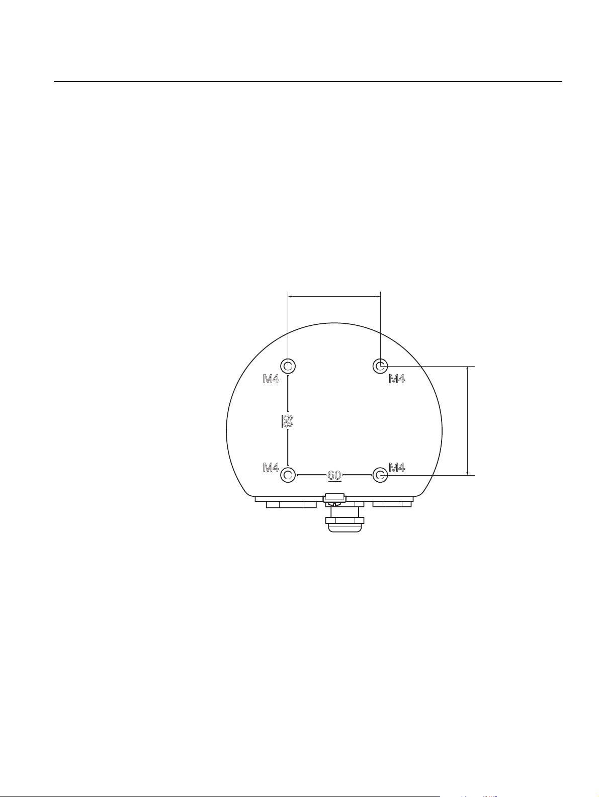
3.2.2 Mounting the Graphical Display
Figure 3-2. Mounting hole
pattern
The Rosemount 2230 Graphical Field Display is designed for mounting on a
plate, wall, or pipe.
Mounting on a Plate
The 2230 display can be mounted on a plate by attaching four M4 screws to
the back of the display. To mount the 2230:
1. Drill four holes in the plate according to the hole pattern on the back of
the 2230 display as illustrated in Figure 3-2.
2. Mount the 2230 on the plate using four M4 screws. Note that the M4
screws that are shipped with the 2230 display can be used as long as the
plate thickness does not exceed 5 mm (0.2 in.).
60 mm (2.4 in.)
68 mm (2.7 in.)
Section 3. Installation
3-3
Page 30
Rosemount 2230
Reference Manual
00809-0100-2230, Rev BB
August 2014
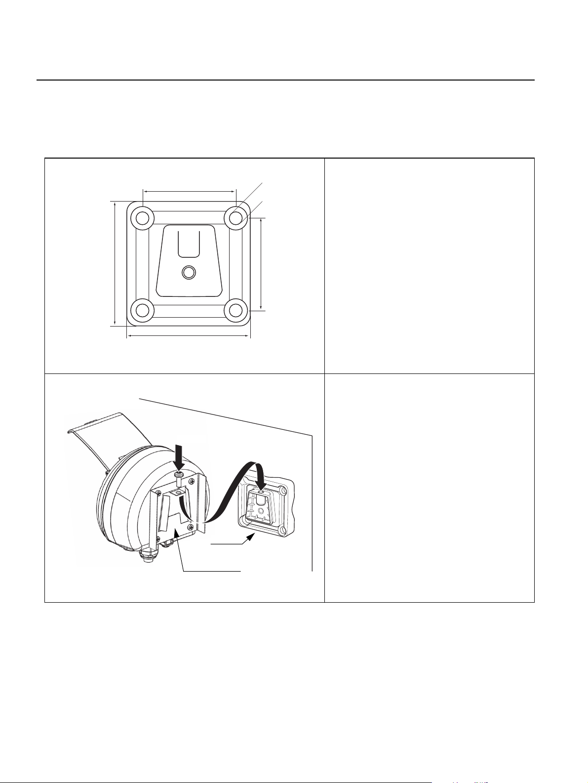
Wall Mounting with Bracket
The Rosemount 2230 Graphical Field Display can be mounted on a wall by
using the optional mounting kit supplied by Rosemount Tank Gauging.
1. Mount the bracket on the wall by using
70 mm
Ø 9 mm
four M8 screws and flat washers.
Note! Countersunk screws are not
suitable.
94 mm
94 mm
Screw
70 mm
2. Attach the mounting plate to the back of
the 2230 housing.
3. Attach the 2230 display to the bracket
on the wall and tighten the locking
screw.
Bracket
3-4
Mounting plate
Section 3. Installation
Page 31

Reference Manual
00809-0100-2230, Rev BB
August 2014
Bracket
Rosemount 2230
Pipe Mounting
The 2230 can be mounted on pipes ranging from a diameter of 33 to 60 mm
by using an optional mounting kit supplied by Rosemount Tank Gauging.
1. Attach the bracket to the pipe.
4 nuts and
washers
2. Ensure that the 2230 is placed in a
direction so that the display is clearly
visible and wiring can be properly
connected.
3. Tighten the nuts. Use moderate torque
to ensure that the bracket does not
break.
Mounting plate
Screw
4. Attach the mounting plate to the back of
the 2230 housing.
5. Attach the 2230 to the bracket by sliding
it from the top downwards.
Bracket
6. Secure the 2230 to the bracket by
tightening the locking screw.
Section 3. Installation
3-5
Page 32

Rosemount 2230
3.3 ELECTRICAL INSTALLATION
Reference Manual
00809-0100-2230, Rev BB
August 2014
3.3.1 Cable/Conduit
Entries
The electronics housing has three entries, two M20×1.5 and one M25×1.5
(Optional: adapters for two ½ - 14 NPT and one ¾- NPT). Minifast and
eurofast adapters are also available. The connections are made in
accordance with local or plant electrical codes.
Make sure that unused ports are properly sealed to prevent moisture or other
contamination from entering the electronics housing.
NOTE!
Use a enclosed metal plug to seal the unused entry/entries. The plastic plugs
mounted at delivery are not sufficient as seal!
3.3.2 Grounding The housing should always be grounded in accordance with national and
local electrical codes. Failure to do so may impair the protection provided by
the equipment. The most effective grounding method is direct connection to
earth ground with minimal impedance.
There is an external grounding screw located at the bottom of the housing and
an internal grounding screw located inside the housing, see Figure 3-3.
The internal ground screw is identified by a ground symbol: .
Figure 3-3. Grounding screws
3-6
Internal ground
NOTE!
When grounding the display via threaded conduit, make sure the connection
provides sufficient low impedance.
External ground
Cable diameter
minimum 4 mm
2
Section 3. Installation
Page 33

Reference Manual
00809-0100-2230, Rev BB
August 2014
Rosemount 2230
Grounding - FOUNDATION™ Fieldbus
Signal wiring of the fieldbus segment must not be grounded. Grounding one
of the signal wires will shut down the entire fieldbus segment.
Shield Wire Connection
To protect the fieldbus segment from noise, grounding techniques for shield
wire usually require a single grounding point for shield wire to avoid creating a
ground loop. The ground point is typically at the power supply (Rosemount
2410 Tank Hub).
The Rosemount Tank Gauging devices are designed for “daisy-chain”
connection of shield wiring in order to enable a continuous shield throughout
the Tankbus network. The shield wire terminal in the 2230 is not connected to
ground. It merely provides electrical continuity to daisy-chained Tankbus
cables.
3.3.3 Cable Selection Use shielded twisted pair wiring for the Rosemount 2230 in order to comply
with FISCO
(1)
requirements and EMC regulations. The cables must be
approved for use in hazardous areas, where applicable. In the U.S.
explosion-proof conduits may be used in the vicinity of the vessel.
We recommend cable size 0.75 mm2 (18 AWG) in order to facilitate wiring.
Cables within the range 22 AWG to 16 AWG (0.5 t o1.5 mm²) can be used in
order to minimize the voltage drop to the 2230 display.
Tankbus cabling must be approved for use in minimum 85°C to match
requirements for all devices in a Rosemount Tank Gauging system.
The FISCO specification requires that cables for the Tankbus comply with the
following parameters:
Table 3-1. FISCO cable
parameters
Parameter Value
Loop resistance 15/km to 150/km
Loop inductance 0.4 mH/km to 1 mH/km
Capacitance 45 nF/km to 200 nF/km
Maximum length of each spur cable 60 m in apparatus class IIC and IIB
Maximum length of each trunk cable 1000 m in apparatus class IIC and 1900 m in
apparatus class IIB
3.3.4 Hazardous Areas When the Rosemount 2230 is installed in a hazardous area, national and
local regulations and specifications in applicable certificates must be
observed, see Appendix B: Product Certifications.
3.3.5 Power Requirements
Section 3. Installation
The Rosemount 2230 is powered over the intrinsically safe Tankbus by the
Rosemount 2410 Tank Hub. The 2410 feeds the intrinsically safe fieldbus
segment by acting as a FISCO power supply on the Tankbus (9 - 17.5 Vdc,
polarity insensitive). The 2230 has a current consumption of 30 mA.
See the Rosemount 2410 Reference Manual (Document no. 305030EN) for
more information.
When installed in a FOUNDATION fieldbus system, the Rosemount 2230 is
powered by the FF segment with standard fieldbus power supplies.
(1) See IEC 61158-2 and IEC/TS 60079-27:2002.
3-7
Page 34

Reference Manual
Rosemount 2230
00809-0100-2230, Rev BB
August 2014
3.3.6 The Tankbus The Rosemount Tank Gauging system is easy to install and wire. Devices can
be “daisy-chained” thus reducing the number of segment couplers.
In a Rosemount Tank Gauging system devices communicate with a
Rosemount 2410 Tank Hub via the intrinsically safe Tankbus. The Tankbus
complies with the FISCO
2410 acts as power supply to the field devices on the Tankbus.
Termination
A terminator is needed at each end of a FOUNDATION Fieldbus network.
Generally, one terminator is placed in the fieldbus power supply, and the other
one in the last device in the fieldbus network.
NOTE!
Ensure that there are two terminators on the fieldbus.
The Rosemount 2410 Tank Hub acts as power supply. Since the 2410
normally is the first device in the fieldbus segment, the built-in termination is
enabled at factory.
(1)
FOUNDATION fieldbus standard. The Rosemount
Other devices such as the Rosemount 5900S Radar Level Gauge, the
Rosemount 2230 Graphical Field Display, and the Rosemount 2240S
Multi-input Temperature Transmitter also have built-in terminators which can
easily be enabled by inserting a jumper in the terminal block when necessary.
Segment design
When designing a FISCO fieldbus segment a few requirements need to be
considered. Cabling has to comply with FISCO requirements as described in
“Cable Selection” on page 3-7.
You will also have to ensure that the total operating current of the connected
field devices is within the output capability of the Rosemount 2410 Tank Hub.
The 2410 is able to deliver 250 mA. In a Smart Wireless System the
maximum current is 200 mA. Consequently, the number of field devices has to
be considered so that the total current consumption is less than the available
current. See section “Power Budget” in the Rosemount 2410 Reference
Manual (Document No. 300530EN) for more information
Another requirement is to ensure that all field devices have at least 9 V input
voltage at their terminals. Therefore you will have to take into account the
voltage drop in the fieldbus cables.
Distances are normally quite short between the Rosemount 2410 Tank Hub
and field devices on the tank. In many cases you can use existing cables as
long as the FISCO requirements are fulfilled (see “Cable Selection” on
page 3-7).
See section ”The Tankbus” in the Rosemount 2410 Reference Manual
(Document no. 305030EN) for more information on segment design of a
Rosemount Tank Gauging system.
3-8
(1) FISCO=Fieldbus Intrinsically Safe Concept
Section 3. Installation
Page 35

Reference Manual
00809-0100-2230, Rev BB
August 2014
Rosemount 2230
3.3.7 Typical installations
Figure 3-4. Example of Tankbus
connection for a single tank
2410 Tank Hub with
intrinsically safe power
supply, integrated power
conditioner, and built-in
terminator
The example below in Figure 3-4 illustrates a system with terminators at both
ends of the fieldbus segment as required in a FOUNDATION fieldbus system. In
this case terminators are enabled in the Rosemount 2410 Tank Hub and a
field device at the end of the network segment.
Tankbus length up to 1000 meter depending
on number of devices and cable quality
Built-in terminator
2230 Display
5900S Radar
Level Gauge
Tankbus
2240S Temperature
Transmitter
Built-in
terminator
enabled on the
last device
The maximum distance between the 2410 Tank Hub and the field devices on
the tank depends on the number of devices connected to the Tankbus and the
quality of cables.
See chapter “Electrical Installation” in the Rosemount 2410 Reference
Manual (Document no. 305030EN) for more information about cable
selection, power budget, and the 2410 Tankbus.
See also “Typical Installations” in the Rosemount 2410 Reference Manual
(Document no. 305030EN) for more examples of how to install Rosemount
Tank Gauging systems that include the 2410 Tank Hub.
Section 3. Installation
3-9
Page 36

Rosemount 2230
Reference Manual
00809-0100-2230, Rev BB
August 2014
3.3.8 2230 in
OUNDATION
F
fieldbus systems
Figure 3-5. Example of an I.S.
FOUNDATION fieldbus system
FISCO/Entity compliant
FM USA, FM Canada:
AIS Class I, Division 1
ATEX and IECEx:
Ex [ia], or Ex [ib] (FISCO)
Ex [ia] (Entity)
The Rosemount 2230 Display supports the FOUNDATION fieldbus (FF)
technology and lets you integrate a 2230 into an existing FF network. As long
as the power supply meets certain requirements (see Figure 3-5 and
Figure 3-6) the 2230
I.S. Power Supply
(1)
will be able to operate as any other FF device.
2230 Display
Trunk
Segment
Coupler
2240S Temperature
Transmitter
5900S Radar Level
Gauge
Ensure that the power supply is able to provide the total current needed for all
the connected devices. See “Power Requirements” on page 3-7 for further
information.
Figure 3-6. Example of a
Non-I.S. FOUNDATION fieldbus
system
Non-I.S. Power Supply
Ensure that the 2230 and other devices connected to the FOUNDATION
fieldbus (FF) system are compliant with the FISCO or Entity parameters of the
power supply.
Ensure that the short circuit protection of the Segment Coupler
(2)
current consumption of the connected devices.
SAFE AREA HAZARDOUS AREA
2230 Display
Barrier
IS Trunk
FISCO/Entity compliant
FM USA, FM Canada:
AIS Class I, Division 1
ATEX and IECEx:
Ex [ia], or Ex [ib] (FISCO)
Ex [ia] (Entity)
Segment
Coupler
2240S Temperature
Transmitter
5900S Radar Level
Gauge
matches the
3-10
(1) See Appendix B: Product Certifications for 2230 approval information
(2) See the Rosemount 2410 Reference Manual (Document No. 300530EN) for more informa-
tion on the Segment Coupler.
Section 3. Installation
Page 37

Reference Manual
00809-0100-2230, Rev BB
August 2014
Rosemount 2230
3.3.9 Wiring Use the following wiring procedure for the Rosemount 2230:
1. Unscrew and remove all screws at the front of the display.
2. Remove the cover carefully. Take care of the locking spring for the
weather protection hatch, see “2230 Components” on page 2-2.
NOTE!
Do not disconnect the cables between the display front and the circuit board.
Ensure that the compartment is protected against water in case of rain.
3. Run the Tankbus cable through the gland.
4. Connect the Tankbus wires to the X2 and X3 terminals as illustrated in
Figure 3-7 on page 3-12. Ensure that the positive lead is connected to
the terminal marked FB+ and the negative lead to the terminal marked
FB-.
5. Connect the cable shield to the “Shield Loop Through” (X1) terminal.
6. If the 2230 display is the last device on the Tankbus, connect a jumper
for the built-in termination. See “The Tankbus” on page 3-8 for more
information on termination.
7. Replace the cover. Make sure that the sealing and the locking device for
the weather protection hatch are placed in the correct positions.
8. Firmly tighten the screws on the front cover.
NOTE!
Ensure that o-rings and seats are in good condition prior to mounting the
cover in order to maintain the specified level of ingress protection. The same
requirements apply for cable inlets and outlets (or plugs). Cables must be
properly attached to the cable glands.
Section 3. Installation
3-11
Page 38

Rosemount 2230
Figure 3-7. 2230 cable
connections
Front cover
Sealing
00809-0100-2230, Rev BB
X2: Tankbus (+) output
X3: Tankbus (-) output
Reference Manual
August 2014
Daisy-chain
connection to other
field devices
(see page 3-13)
Jumper for
built-in
termination
Internal grounding
X2: Tankbus FB+ input
X3: Tankbus FB- input
Cable Shield
X4: Tankbus
terminator
FB+ FB-
3-12
Section 3. Installation
Page 39

Reference Manual
00809-0100-2230, Rev BB
August 2014
Figure 3-8. Daisy-chain wiring
Rosemount 2230
Daisy-Chain Connection
You may use the daisy-chain option in order to connect the Rosemount 2230
to other field devices on the Tankbus:
1. Unscrew and remove all six screws on the front of the Rosemount 2230.
Remove the cover carefully. Take care of the locking device for the
weather protection hatch.
NOTE!
Do not disconnect the cables between the display front and the circuit board.
2. Disconnect the termination jumper from the X3 terminal, see Figure 3-7
on page 3-12.
3. Run the new Tankbus cable into the 2230 compartment through a
suitable gland.
4. Connect the outgoing Tankbus wires to the X2-out and X3-out terminals
as shown in Figure 3-8.
X2: out
Figure 3-9. Wiring diagram for
Rosemount 2230
Shield Wire
connected at
power supply
X3: out
X1: Cable Shield
5. Connect the cable shield to the X1 terminal.
6. Replace the cover. Make sure the sealing and the locking device for the
weather protection hatch are placed in the correct positions.
7. Firmly tighten the six screws on the front cover.
As illustrated in Figure 3-9 the Rosemount 2230 can be daisy-chained to
other field devices via the Tankbus.
Rosemount 2230 Rosemount 2410 Rosemount 5900S Rosemount 2240S
Built-in
terminator
enabled on
the last device
Section 3. Installation
Tankbus
3-13
Page 40

Rosemount 2230
Reference Manual
00809-0100-2230, Rev BB
August 2014
3.4 LED SIGNALS AND RESET BUTTON
Figure 3-10. LED Signals
The Rosemount 2230 has three LED signals that show communication and
status.
Reset button
Tankbus Receive
(yellow)
Tankbus Transmit
(green)
Status LED
Status LED
Using different blinking sequences, the status LED indicates error codes. In
normal operation the LED flashes every other second. When an error occurs,
the LED flashes a sequence that corresponds to a code number followed by a
five second pause. This sequence is continuously repeated (for more
information see “Device Error Signals” on page 5-6).
Communication LED:s
Tankbus communication is indicated by a pair of LED:s, see Figure 3-10.
When you connect the Tankbus cables you can check the communication
status with the LED:s.
Reset Button
You may use the Reset button to force a restart of the Rosemount 2230
display. Restarting the 2230 has the same effect as switching off and on the
power supply.
The Restart option will connect the Rosemount 2230 display to the
Rosemount 2410 Tank Hub and perform start-up tests of software and
hardware.
3-14
Section 3. Installation
Page 41

Reference Manual
00809-0100-2230, Rev BB
August 2014
Rosemount 2230
3.5 SWITCHES
3.5.1 DIP Switches The Rosemount 2230 is equipped with four DIP switches as illustrated in
Figure 3-11.
Figure 3-11. DIP Switches
Table 3-2. Rosemount 2230
DIP Switches
The switches control the following settings:
Number Name Description
1 Simulate
2 Write Protect Enables write protection of configuration data.
3 Spare Not used
4 Spare Not used
Enables simulation for test of Field Diagnostics in open
FF systems.
NOTE!
Manual configuration may override the switch setting.
Simulate Switch
The Simulate switch is used for simulation of Field Diagnostics conditions,
useful when testing the alarm setup.
Write Protect Switch
The Write Protect switch can be used to protect the Rosemount 2230 from
unintentional changes of the current configuration. See also “Write Protection”
on page 5-25.
Section 3. Installation
3-15
Page 42

Rosemount 2230
Reference Manual
00809-0100-2230, Rev BB
August 2014
3.6 AMBIENT TEMPERATURE
The Rosemount 2230 is equipped with a temperature sensor for measuring
ambient temperature. The temperature can be displayed on the field display
and in the TankMaster software.
The ambient temperature affects the readability and response time of the
LCD. This is particularly notable in extremely cold weather. The 2230
automatically adjusts the LCD contrast based on the ambient temperature.
The temperature sensor also controls the minimum toggle time used by the
2230 Display.
3-16
Section 3. Installation
Page 43

Reference Manual
00809-0100-2230, Rev BB
August 2014
Rosemount 2230
Section 4 Configuration and Operation
4.1 Safety Messages . . . . . . . . . . . . . . . . . . . . . . . . . . . . page 4-1
4.2 Introduction . . . . . . . . . . . . . . . . . . . . . . . . . . . . . . . . page 4-3
4.3 Menu Tree . . . . . . . . . . . . . . . . . . . . . . . . . . . . . . . . . page 4-7
4.4 The Main Menu . . . . . . . . . . . . . . . . . . . . . . . . . . . . . page 4-8
4.5 The Select View Menu . . . . . . . . . . . . . . . . . . . . . . . page 4-9
4.6 The Options Menu . . . . . . . . . . . . . . . . . . . . . . . . . . page 4-10
4.7 The Service Menu . . . . . . . . . . . . . . . . . . . . . . . . . . . page 4-17
4.8 FOUNDATION Fieldbus Overview . . . . . . . . . . . . . . . . page 4-22
4.9 Device Capabilities . . . . . . . . . . . . . . . . . . . . . . . . . .page 4-23
4.10 General Block Information . . . . . . . . . . . . . . . . . . . . page 4-24
4.11 Multiple Analog Output Blocks . . . . . . . . . . . . . . . . page 4-25
4.12 Resource Block . . . . . . . . . . . . . . . . . . . . . . . . . . . . page 4-27
4.13 475 Field Communicator Menu Tree . . . . . . . . . . . .page 4-33
4.14 Configuration Using AMS Device Manager . . . . . . page 4-34
4.15 Alert Setup . . . . . . . . . . . . . . . . . . . . . . . . . . . . . . . . . page 4-40
4.1 SAFETY MESSAGES
Procedures and instructions in this section may require special precautions to
ensure the safety of the personnel performing the operations. Information that
raises potential safety issues is indicated by a warning symbol ( ). Please
refer to the following safety messages before performing an operation
preceded by this symbol.
Failure to follow safe installation and servicing guidelines could result in death or
serious injury:
Make sure only qualified personnel perform the installation.
Use the equipment only as specified in this manual. Failure to do so may impair the
protection provided by the equipment.
Do not perform any service other than those contained in this manual unless you are
qualified.
www.rosemount-tg.com
Page 44

Rosemount 2230
Reference Manual
00809-0100-2230, Rev BB
August 2014
Explosions could result in death or serious injury:
Verify that the operating environment of the display is consistent with the appropriate
hazardous locations certifications.
Before connecting a hand held communicator in an explosive atmosphere, make sure
the instruments in the loop are installed in accordance with intrinsically safe or
non-incendive field wiring practices.
Do not remove the device cover in explosive atmospheres when the circuit is alive.
4-2
Section 4. Configuration and Operation
Page 45

Reference Manual
00809-0100-2230, Rev BB
August 2014
Rosemount 2230
4.2 INTRODUCTION This chapter provides information about configuration and operation of the
Rosemount 2230 Graphical Field Display.
For information on how to use TankMaster WinSetup to configure the 2230,
see the Raptor System Configuration Manual (Document no.300510EN).
4.2.1 The 2230
Graphical Field
Display
Figure 4-1. The
Rosemount 2230 display
The Rosemount 2230 is a graphical display designed for viewing tank data in
tough environments. It features adjustable LCD contrast, backlight,
multi-language support, and communication failure indication.
The Rosemount 2230 can be used in systems based on the Rosemount 2410
Tank Hub as well as in Foundation fieldbus networks. The 2230 automatically
detects which kind of system it is connected to.
The four softkeys allow you to navigate through the different menus and to
select various functions for tank data viewing and service.
Menu: opens the Main Menu with various options for configuration of the
2230 display.
Pause: stops toggling the measurement variables until the Resume button is
pressed.
Down arrow : lets you scroll through the list of measurement variables and
tanks.
Status: lets you view the current status of the presented measurement
variable. See also “Status Information” on page 5-12.
A symbol in the upper right-hand corner of the display indicates that the 2230
is operating and communicates on the Tankbus.
Weather protection lid
The Rosemount 2230 is powered by the Tankbus (see “Power Requirements”
on page 3-7).
Section 4. Configuration and Operation
Note! It is recommended that
the lid is closed whenever
possible to protect the LCD
from exposure by ultraviolet
radiation from the sun
Activity indicator
Display
Softkey functions
Softkeys
4-3
Page 46

Rosemount 2230
Reference Manual
00809-0100-2230, Rev BB
August 2014
Adjusting the display contrast
The 2230 automatically adjusts display contrast to optimize for changes of
ambient temperature. The contrast can be manually adjusted when further
fine-tuning is desired. To increase the display contrast, press the two buttons
on the right-hand side simultaneously. To decrease the contrast, press the
two buttons on the left-hand side. It takes approximately 10 seconds to adjust
from minimum to maximum contrast.
The contrast can also be adjusted by using the Contrast service command:
<Menu><Service><LCD Contrast>.
4.2.2 Configuration Tools
Different tools are available for configuration of a Rosemount 2230.
In Rosemount 2410 Tank Hub systems:
• Rosemount TankMaster Winsetup
In FOUNDATION fieldbus systems:
• Rosemount 475 Field Communicator
• AMS Device Manager for FOUNDATION fieldbus systems
•FOUNDATION fieldbus hosts supporting DD4
TankMaster is an Emerson Process Management/Rosemount Tank Gauging
inventory management software package for installation and configuration of
tank gauging field devices. The WinSetup package provides you with
powerful and easy-to-use tools for installation and configuration. See the
Raptor System Configuration Manual (Document no. 300510EN) for more
information on how to configure the 2230 Display by using TankMaster
Winsetup.
For DeltaV users, the DD can be found at www.easydeltav.com. For other
hosts that use Device Descriptions (DD) and DD Methods for device
configuration, the latest DD versions can be found on FOUNDATION’S website
at www.fieldbus.org.
4-4
Section 4. Configuration and Operation
Page 47

Reference Manual
00809-0100-2230, Rev BB
August 2014
Rosemount 2230
4.2.3 Activity and Alarm Indication
Figure 4-2. Simulated or manual
value
The Rosemount 2230 display shows a warning symbol for simulated or
manual measurement values as illustrated in Figure 4-2 and Figure 4-3.
Manual or simulated measurement values are indicated by an alarm symbol
as shown in Figure 4-2.
Alarm symbol
Figure 4-3. Invalid value For invalid measurement data, the alarm symbol is displayed and no data
appears in the measurement value field as illustrated in Figure 4-3.
Invalid value
Figure 4-4. Activity indicator The activity indicator spins continuously to indicate that the 2230 is operating
normally. In case of a communication problem an alarm symbol is displayed
instead.
Activity indicator for normal operation
Communication problems
Section 4. Configuration and Operation
4-5
Page 48

Rosemount 2230
Reference Manual
00809-0100-2230, Rev BB
August 2014
4.2.4 Start-Up Procedure
Figure 4-5. Test screen
Figure 4-6. Start-up screen
When the Rosemount 2230 display is powered on, a test of the LCD screen is
performed.
Test pattern
After the LCD test is done the start-up screen will appear.
Figure 4-7. View Mode
Once the start-up procedure is finished the 2230 will return to the view that
was used last time the 2230 was powered.
4-6
Section 4. Configuration and Operation
Page 49

Reference Manual
00809-0100-2230, Rev BB
August 2014
Rosemount 2230
4.3 MENU TREE The Rosemount 2230 lets you navigate in a menu structure as illustrated in
Figure 4-8:
Figure 4-8. Rosemount 2230
Menu Tree
Section 4. Configuration and Operation
4-7
Page 50

Reference Manual
Rosemount 2230
00809-0100-2230, Rev BB
August 2014
4.4 THE MAIN MENU In normal operation the Rosemount 2230 display is in View Mode and shows
the current measurement values for the selected tanks. In case of an alarm, a
graphical symbol appears on the screen.
Figure 4-9. Rosemount 2230
Graphical Field Display in View
Mode
Press the Menu
softkey to
navigate to the
Main Menu
Figure 4-10. The Main menu
To navigate from View Mode to the Main Menu, press the Menu softkey on
the left-hand side.
The Main Menu includes the following options:
Select View which lets you select the preferred view, see section “The Select
View Menu” on page 4-9.
Options which lets you select variables and tanks to display, as well as
measurement units, toggle time, and language. See section “The Options
Menu” on page 4-10.
Service which includes the functions Status, Custody Transfer View, LCD
Test, Restart, and Factory Settings. It also includes the About option which
shows the current software version. See section “The Service Menu” on
page 4-17.
4-8
Section 4. Configuration and Operation
Page 51

Reference Manual
00809-0100-2230, Rev BB
August 2014
Rosemount 2230
4.5 THE SELECT VIEW MENU
Figure 4-11. The Main menu
Figure 4-12. The Select View
menu
In the Select View menu, you can specify the number of measurement values
to be displayed in View Mode. To configure the Select View menu:
1. In View Mode, press the <Menu> button to navigate to the Main menu.
2. Highlight the Select View menu item using the and softkeys.
3. Press the softkey.
Figure 4-13. Example of display
configuration with Two values
4. In the Select View Menu, use the up and down arrow softkeys to
navigate to the desired option.
5. Press the <OK> softkey to select the desired option. The Rosemount
2230 returns to View Mode.
For example, using the Two Values option will present a view as illustrated in
Figure 4-13:
Section 4. Configuration and Operation
4-9
Page 52

Rosemount 2230
Reference Manual
00809-0100-2230, Rev BB
August 2014
4.6 THE OPTIONS MENU
Figure 4-14. The Main menu
Figure 4-15. The Options menu
In the Options Menu, the following items are available for a Rosemount 2230
in a Rosemount 2410 Tank Hub system:
• Variables
• Tanks
(1)
(1)
• Units for Display
• Toggle Time
• Language
To choose an item in the Options menu:
1. In View Mode, press the <Menu> button to open the Main menu:
2. Highlight the Options menu item by using the and softkeys.
3. Press the softkey.
Figure 4-16. The Options menu
in a Foundation fieldbus system
4-10
In Foundation fieldbus systems some options are not available. This is
indicated as illustrated below:
4. In the Options Menu, use the up and down arrow softkeys to navigate to
the desired menu item.
5. Press the softkey to continue to the selected menu.
(1) Not available in Foundation fieldbus systems
Section 4. Configuration and Operation
Page 53

Reference Manual
00809-0100-2230, Rev BB
August 2014
Rosemount 2230
4.6.1 Variables In the Select Variables menu
View Mode. The following options are available:
• Tank Pos 1-10
presented for all tanks
• Tk Pos 1, 2, 3... lets you configure variables individually for each tank
For a list of available variables see Table 4-1 on page 4-12.
Select Variables Menu
The Select Variables menu allows you to select variables to be displayed in
View Mode. Option “Tank Pos 1-10” can be used to specify a common set of
variables to be used for all tanks connected to the same 2410 Tank Hub. In
addition to this you can configure tanks individually by specifying a unique set
of variables for each tank. Note that the individual configuration will be added
to the configuration that is common for all tanks.
For a list of selectable variables, see Table 4-1 on page 4-12.
To select variables:
1. In View Mode, press <Menu> <Options> <Variables>.
Figure 4-17. The Select
Variables menu
(2)
lets you configure a common set of variables to be
(1)
, you can choose which variables to present in
Figure 4-18. The Select
Variables Custom option
2. Use the up and down arrow softkeys to navigate to the desired Tank
Position item.
3. Press the <OK> softkey to continue to the Selected Variables list.
4. In the Select Variables list, choose the variables you wish to show in
View Mode.
5. When finished, press <OK> to return to View Mode.
(1) Not available in Foundation fieldbus systems
(2) Tank Position refers to the position in the tank database for the 2410 Tank Hub.
Section 4. Configuration and Operation
4-11
Page 54

Rosemount 2230
Table 4-1. Selectable variables
Reference Manual
00809-0100-2230, Rev BB
August 2014
Variable Description
Level Product level in the displayed tank.
Ullage Ullage is the distance from the Tank Reference
Point to the product surface.
Level Rate How the product in the tank moves when emptying
or filling the tank.
Signal Strength The signal strength of the radar level gauge.
Free Water Level The level of water in the bottom of the tank.
Available when a water level sensor is connected
to the tank.
Vapor Pressure Measured vapor pressure.
Liquid Pressure Measured liquid pressure.
Air Pressure Measured air pressure in the tank.
Ambient Temperature Air temperature outside the tank.
Vapor Temperature Temperature of vapor inside the tank.
Liquid Average Temperature Averagte temperature of the product in the tank.
Tank Temperature Average temperature of the product and vapor in
the tank.
Temperature 1 To 16 Individual temperature of each selected
temperature spot element.
Observed Density Calculated density based on the product level and
pressure.
Reference Density Reference density as specified with the
configuration tool.
Flow rate Measured flow rate.
Tot Obs Volume Total observed product volume in the tank.
User defined 1 t o5 Custom measurement variable.
Middle Pressure Measured pressure from transmitter P2.
Tank Height Tank Reference Height
Level Difference between two product levels.
Bargraph Level Product level presented in a bar graph.
Bargraph Ullage Ullage value presented in a bar graph.
4-12
Select Variables in TankMaster WinSetup
Variables to present in the View Mode can also be configured by using the
TankMaster WinSetup configuration program. For more information see the
Raptor System Configuration Manual (Document no.300510EN).
Section 4. Configuration and Operation
Page 55

Reference Manual
00809-0100-2230, Rev BB
August 2014
Rosemount 2230
4.6.2 Select Tanks In the Select Tanks menu
Mode. The following items are available:
• Default which lets you view all tanks that are configured in the Tank
Database of the 2410 Tank Hub
• All which displays all available tanks in View Mode
• Tank Pos 1-10 which lets you choose the tanks to present in View
Mode
Tank Position 1-10
The Tank Pos 1-10 menu lets you select which tanks to present in View
Mode. Up to ten tanks can be displayed. Note that the tanks need to be
configured in the tank database of the Rosemount 2410 Tank Hub
To select tanks:
1. In View Mode, press <Menu> <Options> <Select Tanks>:
Figure 4-19. The Select Tanks
menu
(1)
, you can specify which tanks to show in View
(2)
.
Figure 4-20. The Select Tanks
Custom option
2. Use the up and down arrow softkeys to navigate to the Tank Pos 1-10
menu item.
3. Press the <OK> softkey to continue to the list of tanks:
4. Use the up and down arrow softkeys to navigate to the desired tank.
5. Press the <On/Off> softkey to select the tank.
6. When finished, press the <OK> softkey to return to View Mode.
(1) Not available in Foundation fieldbus systems
(2) See the Rosemount 2410 Tank Hub Reference Manual (Document no. 300530en)
Section 4. Configuration and Operation
4-13
Page 56

Reference Manual
Rosemount 2230
00809-0100-2230, Rev BB
August 2014
4.6.3 Units for Display In the Units for Display menu, you can see which measurement units that are
used for the displayed variables. The available measurement units are listed
in Table 4-2 on page 4-15.
To change measurement unit:
1. In View Mode, press <Menu> <Options> <Units for Display>:
Figure 4-21. The Units for
Display menu
2. Use the up and down arrow softkeys to navigate to the desired variable
menu item. In the example above, the Length variable was chosen.
3. Press the softkey to continue to the list of options for the selected
variable.
Figure 4-22. Select unit for
Length
4. Use the up and down arrow softkeys to navigate to the desired
measurement unit.
5. Press the <OK> softkey to select the unit and return to the Units for
Display list.
See Table 4-2 for a list of available measurement units.
4-14
Section 4. Configuration and Operation
Page 57

Reference Manual
00809-0100-2230, Rev BB
August 2014
Table 4-2. Available
measurement units for the
Rosemount 2230
Rosemount 2230
Variable Available Measurement Units
Auto When Auto is selected the unit that will appear on the
display is controlled by the Multiple Analog Output Block
configuration. See “Configuration Using AMS Device
Manager” on page 4-34.
Length The following units are available for Level and Ullage:
• Millimeter
• Meter
• Feet
• Imperial 1/16
Level rate The following units are available for Level rate:
• Meter/second
• Meter/hour
• Feet/second
• Feet/hour
Flow rate The following units are available for Flow rate:
• Cubic meter/hour
• Barrel/hour
• US gallon/hour
• UK gallon/hour
• Liter/minute
Volume The following units are available for Volume:
• Cubic meter
• Barrel
• US gallon
• UK gallon
• Liter
Temperature The following units are available for Temperature:
• Degrees Celsius
• Degrees Fahrenheit
• Kelvin
Pressure The following units are available for Pressure:
• Bar
• Pascal
• Kilo pascal
• Atmosphere
• PSI
• Bar Absolute
• Bar Gauge
• PSI Absolute
• PSI Gauge
Density The following units are available for Density:
• Kilogram/Cubic m
• Kilogram/Liter
• Degrees API
Voltage Millivolt
Section 4. Configuration and Operation
4-15
Page 58

Reference Manual
Rosemount 2230
00809-0100-2230, Rev BB
August 2014
4.6.4 Toggle Time The Toggle Time parameter specifies the time period that each value, or set
of values, is presented on the display.
To set the Toggle Time:
1. From View Mode, press <Menu> <Options> <Toggle Time>:
Figure 4-23. Set Toggle time
2. Use the up and down arrow softkeys to increase or decrease the Toggle
Time.
3. Press the <OK>softkey to select the desired value and return to View
Mode.
4.6.5 Language To set the display Language:
1. Use the up and down arrow softkeys and navigate to the preferred
language option:
Figure 4-24. Set display
language
2. Press the <OK> softkey to select the language and return to View Mode.
4-16
Section 4. Configuration and Operation
Page 59

Reference Manual
00809-0100-2230, Rev BB
August 2014
Rosemount 2230
4.7 THE SERVICE MENU
Figure 4-25. Service option in
the Main menu
In the Service Menu, the following items are available:
• Status
• Custody Transfer View
(1)
• LCD Test
• LCD Contrast
• Restart
• Factory Settings
(1)
• About
To choose a Service menu item:
1. In View Mode, press the <Menu> button to open the Main menu:
Figure 4-26. The Service menu
2. Use the and softkeys to navigate to the Service option.
3. Press the softkey.
4. Use the up and down arrow softkeys to navigate to the desired menu
item.
5. Press the softkey to continue to the selected menu.
(1) Not available in Foundation fieldbus systems
Section 4. Configuration and Operation
4-17
Page 60

Reference Manual
Rosemount 2230
00809-0100-2230, Rev BB
August 2014
4.7.1 Status The Status screen shows the current status of the 2230. Various error
messages and warnings can be displayed in case of software or hardware
malfunctions. See “Troubleshooting” on page 5-7 for more information.
To view the current status information:
1. In the View Mode, press <Menu> <Service> <Status>:
Figure 4-27. Rosemount 2230
status
2. Press <Esc> to return to the Service menu.
See “Status Information” on page 5-2 for information on various status
messages.
4.7.2 Custody Transfer View
Figure 4-28. Custody Transfer
view
The Custody Transfer view presents Level and Liquid Temperature for each
tank.
To open the Custody Transfer view:
1. In View Mode, press <Menu> <Service> <Custody Transfer>:
2. Press the <Esc> softkey to return to View Mode.
3. Press the <Pause> softkey to pause the display toggling.
4. Press the down arrow softkey to display the next tank.
4-18
Section 4. Configuration and Operation
Page 61

Reference Manual
00809-0100-2230, Rev BB
August 2014
Rosemount 2230
4.7.3 LCD Test In the LCD test two checkered patterns will be displayed testing the whole
display area.
To open the LCD Test view:
1. In View Mode, press <Menu><Service><LCD Test>:
Figure 4-29. LCD test
2. After the test is completed, the display will return to normal View Mode.
4.7.4 LCD Contrast To adjust the LCD contrast:
Figure 4-30. The LCD Contrast
option
1. In View Mode, press <Menu><Service><LCD Contrast>:
2. Use the up and down arrow softkeys to increase or decrease the LCD
contrast.
3. Press the <OK>softkey to select the desired value and return to View
Mode
Section 4. Configuration and Operation
4-19
Page 62

Rosemount 2230
4.7.5 Restart To restart the 2230:
1. In View Mode, press <Menu><Service>:
Figure 4-31. The Restart option
2. Choose the Restart option and press the softkey.
The Restart option will perform start-up tests of software and hardware.
In aTankbus system it will connect the Rosemount 2230 Graphical Field
Display to the Rosemount 2410 Tank Hub.
Reference Manual
00809-0100-2230, Rev BB
August 2014
4.7.6 Factory Settings To restore the 2230 to factory settings:
1. In View Mode, press <Menu><Service>:
Figure 4-32. The Factory
Settings option
2. Choose the Factory Settings option and press the softkey.
Figure 4-33. Confirm Factory
Settings
4-20
3. Press the <OK> softkey to restore the 2230 to factory settings, or press
the <Esc> softkey to cancel.
4. When the Rosemount 2230 is restored to factory settings, all user
configuration will be lost.
Section 4. Configuration and Operation
Page 63

Reference Manual
00809-0100-2230, Rev BB
August 2014
4.7.7 About To view the About information:
1. In View Mode, press <Menu><Service>.
2. Choose the About option and press the softkey.
Figure 4-34. Software revisions
for Rosemount 2230
3. The About option will present the current software version and the 2230
serial number.
4. Press the <Esc> softkey to return to the Service menu.
Rosemount 2230
Section 4. Configuration and Operation
4-21
Page 64

Rosemount 2230
Reference Manual
00809-0100-2230, Rev BB
August 2014
4.8 FOUNDATION FIELDBUS OVERVIEW
This section provides a brief overview of FOUNDATION Fieldbus block
operation with the Rosemount 2230 Graphical Field Display.
For detailed information about FOUNDATION Fieldbus technology and function
blocks used in the Rosemount 2230 Series, refer to Appendix C: Foundation
fieldbus Block Information and the FOUNDATION Fieldbus Block Manual
(Document No. 00809-0100-4783).
4.8.1 Block Operation Function blocks within the fieldbus device perform the various functions
required for process control, such as analog input (AI) functions, as well as
proportional-integral derivative (PID) functions. The standard function blocks
provide a common structure for defining function block inputs, outputs, control
parameters, events, alarms, and modes, and combining them into a process
that can be implemented within a single device or over the fieldbus network.
This simplifies the identification of characteristics that are common to function
blocks.
In addition to function blocks, fieldbus devices contain two other block types
to support the function blocks; the Resource block and the Transducer
block.
Resource blocks contain the hardware specific characteristics associated with
a device; they have no input or output parameters. The algorithm within a
resource block monitors and controls the general operation of the physical
device hardware. There is only one resource block defined for a device.
Transducer blocks connect function blocks to local input/output functions.
They read sensor hardware and write to effector (actuator) hardware.
Resource Block
The Resource block contains diagnostics, hardware, electronics, and mode
handling information. There are no linkable inputs or outputs to the Resource
Block.
Main Transducer Block (TB1100)
The Main Transducer Block contains parameters for configuration of the
Rosemount 2230 Graphical Field Display. It contains device information
including diagnostics and the ability to configure, set to factory defaults and
restart the 2230 Display.
Register Transducer Block (TB1200)
The Register Transducer Block allows a service engineer to access all
database registers in the device.
Multiple Analog Output Block
A Multiple Analog Output (MAO) Block accepts output values from field
devices and assigns them to specified I/O channels in order to make them
available for the display.
Display Transducer Block (TB1300)
The Display Transducer Block includes parameters for setup of the
Rosemount 2230 Graphical Field Display for use in a Fieldbus system. It
handles mapping of the MAO block inputs to the various field device outputs.
4-22
Section 4. Configuration and Operation
Page 65

Reference Manual
00809-0100-2230, Rev BB
August 2014
4.9 DEVICE CAPABILITIES
Rosemount 2230
4.9.1 Link Active Scheduler
4.9.2 Device
Addressing
Table 4-3. Address Ranges for
FOUNDATION fieldbus devices
The Rosemount 2230 can be designated to act as the backup Link Active
Scheduler (LAS) in the event that the LAS is disconnected from the segment.
As the backup LAS, the 2230 will take over the management of
communications until the host is restored.
The host system may provide a configuration tool specifically designed to
designate a particular device as a backup LAS. Otherwise, this can be
configured manually.
Foundation fieldbus devices use addresses divided into four sub ranges as
shown in Table 4-3.
Address range
(decimal)
0 through 15 00 through 0F Reserved.
16 through 247 10 through F7 Permanent devices.
248 through 251 F8 through FB New or decommissioned devices
252 through 255 FC through FF Temporary (“visitor”) devices.
Address range
(hexadecimal)
Allocation
Address range 16 - 247 is
subdivided into addresses that are
LAS capable (lower end) and not
LAS capable (upper end).
Example: 375/475 communicator.
The Link Active Scheduler device (LAS device) probes a list of addresses to
allow devices to come online during normal operation. The LAS can "skip"
probing certain addresses in the range to speed up how long it takes to detect
new devices on the bus.
4.9.3 Capabilities Virtual Communication Relationship (VCRs)
Table 4-4. VCR’s
Maximum number of VCR’s 38
Number of client and server VCR’s 20
Number of publisher VCR’s 20
Number of subscribers VCR’s 32
Number of source VCR’s 2
Number of sink VCR’s 0
Section 4. Configuration and Operation
4-23
Page 66

Rosemount 2230
4.10 GENERAL BLOCK INFORMATION
4.10.1 Modes Changing Modes
To change the operating mode, set the MODE_BLK.TARGET to the desired
mode. After a short delay, the parameter MODE_BLOCK.ACTUAL should
reflect the mode change if the block is operating properly.
Permitted Modes
It is possible to prevent unauthorized changes to the operating mode of a
block. To do this, configure MODE_BLOCK.PERMITTED to allow only the
desired operating modes. It is recommended to always select OOS as one of
the permitted modes.
Types of Modes
For the procedures described in this manual, it will be helpful to understand
the following modes:
AUTO
The functions performed by the block will execute. If the block has any
outputs, these will continue to update. This is typically the normal
operating mode.
Reference Manual
00809-0100-2230, Rev BB
August 2014
Out of Service (OOS)
The functions performed by the block will not execute. If the block has any
outputs, these will typically not update and the status of any values passed
to downstream blocks will be “BAD”. To make some changes to the
configuration of the block, change the mode of the block to OOS. When
the changes are complete, change the mode back to AUTO.
MAN
In this mode, variables that are passed out of the block can be manually
set for testing or override purposes.
NOTE
When an upstream block is set to OOS, this will impact the output status of all
downstream blocks. The figure below describes the hierarchy of blocks:
Resource
Block
Transducer
Block
Other function
blocks
4-24
Section 4. Configuration and Operation
Page 67

Reference Manual
00809-0100-2230, Rev BB
August 2014
Rosemount 2230
4.10.2 Factory Configuration
Table 4-5. Available function
blocks for the 2230
4.11 MULTIPLE ANALOG
OUTPUT BLOCKS
4.11.1 Configure the MAO Blocks
The following fixed configuration of function blocks is provided:
Function Block Index Default Tag Available
Multiple Analog Output 1400 MAO_1400 Permanent
Multiple Analog Output 1500 MAO_1500 Permanent
Multiple Analog Output 1600 MAO_1600 Permanent
Multiple Analog Output 1700 MAO_1700 Permanent
To show input data from MAO blocks on the display, the 2230 needs to be
configured by using FOUNDATION fieldbus parameters available in the Display
Transducer Block (see “Display Transducer Block” on page C-10).
The MAO Block is used for receiving measurement data from devices such as
the Rosemount 5900S Radar Level Gauge. The Rosemount 2230 is supplied
with four pre-configured MAO blocks according to Table 4-5 on page 4-25.
Each MAO block has eight inputs.
Note that the CHANNEL parameter value has to be equal to 1 (auto) in order
to provide data output from the MAO block.
An example of a setup with a Rosemount 2230 receiving data from a
Rosemount 5900S and a Rosemount 2240S is shown in Figure 4-35 on
page 4-26.
Section 4. Configuration and Operation
4-25
Page 68

Rosemount 2230
Reference Manual
00809-0100-2230, Rev BB
August 2014
4.11.2 Application Example
Figure 4-35. Example of a
function block configuration for
the Rosemount 2230
2240S Temperature Transmitter
MAI 1
(Temperature
element 1-8)
AI 4
(Water Level)
5900S Radar Level Gauge
AI 1 (Level)
A 2230 Graphical Field Display configured for receiving level and temperature
measurement data from devices such as the Rosemount 5900S Radar Level
Gauge and the Rosemount 2240S Temperature Transmitter.
2230 GRAPHICAL FIELD DISPLAY
Output 1
Output 2
Output 3
Output 4
Output 5
Output 6
Output 7
Output 8
Out
Out
Input 1
Input 2
Input 3
Input 4
Input 5
Input 6
Input 7
Input 8
Input 1
Input 2
Input 3
Input 4
Input 5
Input 6
Input 7
Input 8
MAO 1
Channel
MAO 2
Channel
MAO 1 Data
MAO 2 Data
AI 6 (Total
Observed Volume)
AI <n>=factory supplied Analog Input block no. <n>
Out
In the example above (Figure 4-35) a 2230 Graphical Field Display receives
data from two field devices; a Rosemount 2240S Temperature Transmitter
and a Rosemount 5900S Radar Level Gauge.
Temperature from eight elements is output from the 2240S via the Multiple
Analog Input Block 1 to the Multiple Analog Output Block 1 of the 2230
Display.
Water Level is output from the 2240S via the Analog Input Block 4 to the
Multiple Analog Output Block 2 of the 2230 Display.
A 5900S outputs product Level and Total Observed Volume via Analog Input
blocks 1 and 6 to the Multiple Analog Output Block 2 of the 2230 Display.
For output of measurement data the 2230 Display can be configured by using
the AMS Device Manager as described in “Configuration Using AMS Device
Manager” on page 4-34.
4-26
Section 4. Configuration and Operation
Page 69

Reference Manual
00809-0100-2230, Rev BB
August 2014
4.12 RESOURCE BLOCK
Rosemount 2230
4.12.1 FEATURES and FEATURES_SEL
The FEATURES parameter is read only and defines which features are
supported by the 2230. Below is a list of the FEATURES the 2230 supports.
FEATURES_SEL is used to turn on any of the supported features that are
found in the FEATURES parameter. The default setting of the Rosemount
2230 is HARD W LOCK. Choose one or more of the supported features if any.
UNICODE
All configurable string variables in the 2230, except tag names, are octet
strings. Either ASCII or Unicode may be used. If the configuration device is
generating Unicode octet strings, you must set the Unicode option bit.
REPORTS
The 2230 supports alert reports. The Reports option bit must be set in the
features bit string to use this feature. Then, the transmitter will actively report
alerts. If it is not set, the host must poll for alerts.
MULTI-BIT ALARM
The 2230 supports Multi-bit alarms. With the multi-bit option enabled each
condition may send a message when it occurs and when it clears so that
there is no masking of active conditions.
SOFT W LOCK and HARD W LOCK
Inputs to the security and write lock functions include the hardware security
switch, the hardware and software write lock bits of the FEATURE_SEL
parameter, and the WRITE_LOCK parameter.
The WRITE_LOCK parameter prevents modification of parameters within the
device except to clear the WRITE_LOCK parameter. During this time, the
block will function normally updating inputs and outputs and executing
algorithms. When the WRITE_LOCK condition is cleared, a WRITE_ALM
alert is generated with a priority that corresponds to the WRITE_PRI
parameter.
The FEATURE_SEL parameter enables the user to select a hardware or
software write lock or no write lock capability. To enable the hardware security
function, enable the HARDW_LOCK bit in the FEATURE_SEL parameter.
When this bit has been enabled the WRITE_LOCK parameter becomes read
only and will reflect the state of the hardware switch.
In order to enable the software write lock, the SOFTW_LOCK bit must be set
in the FEATURE_SEL parameter. Once this bit is set, the WRITE_LOCK
parameter may be set to “Locked” or “Not Locked.” Once the WRITE_LOCK
parameter is set to “Locked” by the software lock, all user requested writes
shall be rejected.
Section 4. Configuration and Operation
4-27
Page 70

Rosemount 2230
The following table displays all possible configurations of the WRITE_LOCK
parameter.
Table 4-6. Possible configuration of the WRITE_LOCK parameter.
Reference Manual
00809-0100-2230, Rev BB
August 2014
FEATURE_SEL
HARDW_LOCK bit
0 (off) 0 (off) NA 1 (unlocked) Read only All
0 (off) 1 (on) NA 1 (unlocked) Read/Write All
0 (off) 1 (on) NA 2 (locked) Read/Write Function Blocks
0 (off) 1 (on) NA 2 (locked) Read/Write None
1 (on) 0 (off)
1 (on) 0 (off) 1 (locked) 2 (locked) Read only Function Blocks
1 (on) 0 (off) 1 (locked) 2 (locked) Read only None
(1) The hardware and software write lock select bits are mutually exclusive and the hardware select has the highest priority. When the
HARDW_LOCK bit if set to 1 (on), the SOFTW_LOCK bit is automatically set to 0 (off) and is read only.
FEATURE_SEL
SOFTW_LOCK bit
(1)
SECURITY
SWITCH WRITE_LOCK
0 (unlocked) 1 (unlocked) Read only All
WRITE_LOCK
Read/Write
Only
Only
Write access to
blocks
4.12.2 MAX_NOTIFY The MAX_NOTIFY parameter value is the maximum number of alert reports
that the resource can have sent without getting a confirmation, corresponding
to the amount of buffer space available for alert messages. The number can
be set lower, to control alert flooding, by adjusting the LIM_NOTIFY
parameter value. If LIM_NOTIFY is set to zero, then no alerts are reported.
4-28
Section 4. Configuration and Operation
Page 71

Reference Manual
00809-0100-2230, Rev BB
August 2014
Rosemount 2230
4.12.3 Field Diagnostic Alerts
The Resource Block acts as a coordinator for Field Diagnostic alerts. There
are four alarm parameters (FD_FAIL_ALM, FD_OFFSPEC_ALM,
FD_MAINT_ALM, and FD_CHECK_ALM) which contain information
regarding some of the device errors which are detected by the transmitter
software.
There is a FD_RECOMMEN_ACT parameter which is used to display the
recommended action text for the highest priority alarm. FD_FAIL_ALM has
the highest priority followed by FD_OFFSPEC_ALM, FD_MAINT_ALM, and
FD_CHECK_ALM which has the lowest priority.
Failure Alarms
A Failure alarm indicates a condition within a device that will make the device
or some part of the device non-operational. This implies that the device is in
need of repair and must be fixed immediately. There are five parameters
associated with FD_FAIL_ALM specifically, they are described below.
FD_FAIL_MAP
This parameter contains a list of conditions in the device which makes the
device non-operational that will cause an alarm to be sent. Below is a list
of the conditions with the highest priority first. This priority is not the same
as the FD_FAIL_PRI parameter described below. It is hard coded within
the device and is not user configurable.
1. Electronics Failure - FF I/O Board
2. Internal Communication Failure
3. Electronics Failure - Main Board
4. Memory Failure - FF I/O Board
5. Database Error
6. Software Failure
FD_FAIL_MASK
This parameter will mask any of the failed conditions listed in
FD_FAIL_MAP. A bit on means that the condition is masked out from
alarming and being broadcast to the host through the alarm parameter.
FD_FAIL_PRI
Designates the alarming priority of the FD_FAIL_ALM, see “Alarm Priority”
on page 4-32. The default is 0 and the recommended values are between
8 and 15.
FD_FAIL_ACTIVE
This parameter displays which of the conditions is active.
FD_FAIL_ALM
Alarm indicating a condition within a device which makes the device
non-operational.
Section 4. Configuration and Operation
4-29
Page 72

Rosemount 2230
Reference Manual
00809-0100-2230, Rev BB
August 2014
Out of Specification Alarms
An Out of Specification alarm indicates that the device operates out of the
specified measurement range. If the condition is ignored, the device will
eventually fail. There are five parameters associated with
FD_OFFSPEC_ALM, they are described below.
FD_OFFSPEC_MAP
The FD_OFFSPEC_MAP parameter contains a list of conditions indicating
that the device or some part of the device operates out of specification.
Below is a list of the conditions with the highest priority first. This priority is
not the same as the FD_OFFSPEC_PRI parameter described below. It is
hard coded within the device and is not user configurable.
Below is a list of the conditions:
1. Invalid Model Code
2. Internal Temperature Out of Limits
3. MAO Fault State Mode Enabled
FD_OFFSPEC_MASK
The FD_OFFSPEC_MASK parameter will mask any of the failed
conditions listed in FD_OFFSPEC_MAP. A bit on means that the condition
is masked out from alarming and being broadcast to the host through the
alarm parameter.
FD_OFFSPEC_PRI
This parameter designates the alarming priority of the
FD_OFFSPEC_ALM, see “Alarm Priority” on page 4-32. The default is 0
and the recommended values are 3 to 7.
FD_OFFSPEC_ACTIVE
The FD_OFFSPEC_ACTIVE parameter displays which of the conditions is
detected as active.
FD_OFFSPEC_ALM
An alarm indicating that the device operates out of the specified
measurement range. If the condition is ignored, the device will eventually
fail.
4-30
Section 4. Configuration and Operation
Page 73

Reference Manual
00809-0100-2230, Rev BB
August 2014
Rosemount 2230
Maintenance Alarms
A Maintenance alarm indicates that the device or some part of the device
needs maintenance soon. If the condition is ignored, the device will eventually
fail. There are five parameters associated with FD_MAINT_ALM, they are
described below.
FD_MAINT_MAP
The FD_MAINT_MAP parameter contains a list of conditions indicating
that the device or some part of the device needs maintenance soon. The
priority is not the same as the MAINT_PRI parameter described below. It is
hard coded within the device and is not user configurable.
Note that maintenance alarms are not enabled by default for the
Rosemount 2230.
FD_MAINT_MASK
The FD_MAINT_MASK parameter will mask any of the failed conditions
listed in FD_MAINT_MAP. A bit on means that the condition is masked out
from alarming and being broadcast to the host through the alarm
parameter.
FD_MAINT_PRI
FD_MAINT_PRI designates the alarming priority of the FD_MAINT_ALM,
see “Alarm Priority” on page 4-32. The default is 0 and the recommended
values are 3 to 7.
FD_MAINT_ACTIVE
The FD_MAINT_ACTIVE parameter displays which of the conditions is
active.
FD_MAINT_ALM
An alarm indicating that the device needs maintenance soon. If the
condition is ignored, the device will eventually fail.
Section 4. Configuration and Operation
4-31
Page 74

Rosemount 2230
Reference Manual
00809-0100-2230, Rev BB
August 2014
Function Check Alarms
A Function Check alarm indicates that the device is temporary non-valid due
to some activities, for example maintenance, on the device.
There are five parameters associated with FD_CHECK_ALM, they are
described below.
FD_CHECK_MAP
The FD_CHECK_MAP parameter contains a list of informative conditions
that do not have a direct impact on the primary functions of the device.
Below is a list of the conditions:
1. Check function
FD_CHECK_MASK
The FD_CHECK_MASK parameter will mask any of the failed conditions
listed in FD_CHECK_MAP. A bit on means the condition is masked out
from alarming and being broadcast to the host through the alarm
parameter.
FD_CHECK_PRI
FD_CHECK_PRI designates the alarming priority of the
FD_CHECK_ALM, see “Alarm Priority” on page 4-32. The default is 0 and
the recommended values are 1 or 2.
FD_CHECK_ACTIVE
The FD_CHECK_ACTIVE parameter displays which of the conditions is
active.
FD_CHECK_ALM
FD_CHECK_ALM is an alarm indicating that the device output is
temporary invalid due to on-going work on the device.
4.12.4 Recommended Actions for Alerts
The FD_RECOMMEN_ACT and RECOMMENDED_ACTION parameters
display text strings that will give a recommended course of action to take
based on which type and which specific event of the alerts that is active (See
Table 5-11 on page 5-16).
4.12.5 Alarm Priority Alarms are grouped into five levels of priority:
Table 4-7. Alarm level priority
Priority Number Priority Description
0 The priority of an alarm condition changes to 0 after the condition that
caused the alarm is corrected.
1 An alarm condition with a priority of 1 is recognized by the system, but is
not reported to the operator.
2 An alarm condition with a priority of 2 is reported to the operator, but does
not require operator attention (such as diagnostics and system alerts).
3-7 Alarm conditions of priority 3 to 7 are advisory alarms of increasing priority.
8-15 Alarm conditions of priority 8 to 15 are critical alarms of increasing priority.
4-32
Section 4. Configuration and Operation
Page 75

Reference Manual
00809-0100-2230, Rev BB
August 2014
Rosemount 2230
4.13 475 FIELD
COMMUNICATOR
The 2230 can be configured by using a 475 Field Communicator. The menu
tree below shows the available options for configuration and service.
MENU TREE
Figure 4-36. Field Communicator Menu Tree
1
1 Device Status
2 Mode
3 Internal Temperature
4 Internal Temp Status
5 Display Setup
6 Device information
1 Overview
2 Configure
3 Service Tools
2
1 Guided Setup
2 Manual Setup
3 Alert Setup
6
1
2
3
1 Identification
2 Revisions
3 Security
1 Display Setup
2 Manual Setup
3 Alert Setup
1 Device
2 MAO Block Mapping
3 Tank Name
4 Custom Parameters
5 Custom Units
6 Classic View
1 FF I/O Board
2 2230 Graphical Field Display
3 Suppressed 2230 Alerts
3
1 Alerts
2 Variables
3 Maintenance
4 Simulate
1
2
3
1 No Active Alerts
2 Alerts Simulation Enabled
1 MAO Block 1
2 MAO Block 2
3 MAO Block 3
4 MAO Block 4
1 Details
2 Reset/Restore
4
1 Alerts
Section 4. Configuration and Operation
4-33
Page 76

Rosemount 2230
Reference Manual
00809-0100-2230, Rev BB
August 2014
4.14 CONFIGURATION USING AMS DEVICE MANAGER
4.14.1 Starting the
Guided Setup
The Rosemount 2230 Graphical Field Display supports DD Methods to
facilitate device configuration. The following description shows how to use the
AMS Device Manager application to configure the Rosemount 2230 in a
FOUNDATION fieldbus system.
Before starting the Guided Setup it is recommended to configure the Multiple
Analog Output (MAO) blocks and connect them to appropriate tank process
variables using Control Studio or a similar application.
To configure the Rosemount 2230 in AMS:
1. From the Start menu; open the AMS Device Manager application.
2. Open the View>Device Explorer.
3. Click the right mouse button or double-click the desired device icon to
open the list of menu options:
Overview
4-34
4. Choose the Overview option.
Section 4. Configuration and Operation
Page 77

Reference Manual
00809-0100-2230, Rev BB
August 2014
Device Status
Rosemount 2230
Guided Setup
Configure
5. The Overview window shows information about the current device
status; Good or Bad. It also gives you access to more detailed
information by pressing the Device Information button.
6. Select the Configure>Guided Setup option to open the Guided Setup
window.
Change Mode
Section 4. Configuration and Operation
4-35
Page 78

Rosemount 2230
Reference Manual
00809-0100-2230, Rev BB
August 2014
7. Set the Display Transducer Block to Out Of Service (OOS) mode by
clicking the Change button.
8. Now proceed with configuration of Multiple Analog Output (MAO) blocks
by pressing the appropriate button; Multiple Analog Output Block (#).
9. The Multiple Analog Output Block window lets you map tanks and tank
parameters from the Multiple Analog Output (MAO) block inputs 1 - 8 to
the tanks and tank parameters in the 2230 Display Transducer block.
This configuration is required in order to make the field device
parameters available on the display output. See section “Multiple Analog
Output Blocks” on page 4-25 for more information on MAO blocks.
Note that MAO Block 1 to MAO Block 4 refer to index number 1400 to
1700 (MAO_1400 - MAO_1700). See section “Factory Configuration” on
page 4-25 for more information.
For each tank you may not configure more than one Tank Parameter of a
certain type. This means that for each tank you may specify one Level,
one Liquid Temperature, etc.
The Bar Graph Minimum and Maximum Value correspond to 0 % and
100 %, respectively. In case you don’t want any bar graph to be
displayed simply leave Minimum Value=0 and Maximum Value=0.
Configure all inputs that are used for the MAO Block.
Note that tank names can be configured in the Manual Setup window,
see “Manual Setup” on page 4-39.
In case there is no tank parameter available that matches the output
from a specific device in the fieldbus network, a custom parameter can
be used instead. A custom parameter can be anything from any device in
the network. Custom parameters can be configured in the Custom
Parameters window as described below.
4-36
Section 4. Configuration and Operation
Page 79

Reference Manual
00809-0100-2230, Rev BB
August 2014
Rosemount 2230
10. Configure all the MAO Blocks that are used. Ensure that unused MAO
block inputs are unconfigured, i.e. that there are no tank numbers or tank
parameters configured for these inputs.
11. Click the Send button to store the current configuration in the device
configuration database.
12. Once the MAO Block mapping is finished, you may proceed with
configuration of custom parameters if needed. Return to the Guided
Setup window and click the Custom Parameters button to open the
Custom Parameters window.
Section 4. Configuration and Operation
13. The Custom Parameters window lets you specify names for various
custom parameters:
• The Long Custom Parameter Name is used for the Single Value view
and the Two Values View on the 2230 Display. It may be up to 20
characters long.
• The Short Custom Parameter Name is used for the Four Values View
on the 2230 Display. It may be up to four characters long.
14. Click the Send button to store the current configuration in the device
configuration database.
15. Proceed with configuration of custom units by clicking the Custom Units
button.
4-37
Page 80

Rosemount 2230
Reference Manual
00809-0100-2230, Rev BB
August 2014
16. In the Custom Units window specify units for the various custom
parameters. The unit label can be specified anyway you like. It does not
need to be a standard unit such as metric or imperial units.
17. Click the Send button to store the current configuration in the device
configuration database.
18. In case you wish to extend device configuration with options not
available in the Guided Setup window, return to the Overview window,
select the Configure>Manual Setup option, and choose the desired tab
(see “Manual Setup” on page 4-39).
4-38
Section 4. Configuration and Operation
Page 81

Reference Manual
00809-0100-2230, Rev BB
August 2014
Rosemount 2230
4.14.2 Manual Setup In case you wish to configure device options not available in the Guided Setup
window, for example specifying tank names, you may use the Manual Setup
option.
To open Manual Setup:
1. Open the AMS Device Manager application.
2. In the Device Explorer, right-click or double-click the desired device icon
to open the list of menu options (see “Starting the Guided Setup” on
page 4-34).
3. Select the Configure>Manual Setup option.
4. Select the desired tab.
Change Mode
Manual Setup
Configure
5. Set the device to Out Of Service (OOS) mode by clicking the Change
button.
6. Choose the desired tab and configure the device. The various tabs gives
you access to various configuration options such as block parameter
mapping, configuration of custom parameters and units, as well as tank
name specification. The Device tab lets you configure display units,
display view and language. It also provides the option to write protect the
2230 (see “Write Protection” on page 5-25).
7. When configuration is finished, click the Apply button to store the current
configuration in the device database.
8. Click the Change button to set the device to operating (Auto) mode.
9. Click the OK button to close the window.
Section 4. Configuration and Operation
4-39
Page 82

Reference Manual
Rosemount 2230
00809-0100-2230, Rev BB
August 2014
4.15 ALERT SETUP The Alert Setup window allows you to configure and enable/disable Alerts.
For details on how to view active alerts see “Viewing Active Alerts in AMS” on
page 5-14.
To open the Alert Setup window:
1. From the Start menu; open the AMS Device Manager application.
2. Open the View >Device Explorer.
3. Right-click or double-click the desired device icon to open the list of
menu options.
4-40
4. Choose the Configure option.
5. Select the Alert Setup option.
Section 4. Configuration and Operation
Page 83

Reference Manual
00809-0100-2230, Rev BB
August 2014
Rosemount 2230
6. Select the desired tab (FF I/O Board or 2230 Graphical Field Display).
7. Configure alerts for the different error types.
8. You may change the configuration for each error type by selecting the
appropriate check box to match your requirements. Note that it is
possible to map an error condition to several alert categories if desired.
For information on the default setup of error types and alerts (Failure,
Maintenance, Out of Specification, and Function Check) see “Alert
Default Settings” on page 4-42.
9. Note that when simulating alerts, only alerts which are setup according to
the default configuration will be simulated, see section “Alert Default
Settings” on page 4-42.
10. Once the configuration is finished, click the OK button to save the current
alert setup.
Section 4. Configuration and Operation
4-41
Page 84

Rosemount 2230
Reference Manual
00809-0100-2230, Rev BB
August 2014
4.15.1 Alert Default Settings
Table 4-8. Default Alert
configuration for FF I/O Board
Table 4-9. Default Alert
configuration for 2230 Graphical
Field Display
The following default settings are used for the FF I/O Board and the 2230
Graphical Field Display. You may configure error types in a different way if
you like. For example, the Internal Temperature Out of Limits error is
configured as a Out of Specification alert for the 2230 by default. The Alert
Setup window allows you to enable the alert as Failed or Function Check
instead.
FF I/O Board
Error type Default configuration Enabled / Disabled
Check Function Function Check Enabled
Electronics failure Main Board Failed alert Enabled
Electronics failure FF I/O Board Failed alert Enabled
Memory Failure FF I/O Board Failed alert Enabled
Internal communication failure Failed alert Enabled
2230 Graphical Field Display
Error type Default configuration Enabled / Disabled
Database error Failed alert Enabled
Internal Temperature Out of Limits Out of Specification alert Enabled
Invalid Model Code Out of Specification alert Enabled
MAO Fault State Mode Enabled Out of Specification alert Enabled
Software failure Failed alert Enabled
4-42
Section 4. Configuration and Operation
Page 85

Reference Manual
00809-0100-2230, Rev BB
August 2014
Rosemount 2230
Section 5 Service and Troubleshooting
5.1 Safety Messages . . . . . . . . . . . . . . . . . . . . . . . . . . . . page 5-1
5.2 Service . . . . . . . . . . . . . . . . . . . . . . . . . . . . . . . . . . . . page 5-2
5.3 Troubleshooting . . . . . . . . . . . . . . . . . . . . . . . . . . . . page 5-7
5.4 Resource Block . . . . . . . . . . . . . . . . . . . . . . . . . . . . page 5-13
5.5 Transducer Block . . . . . . . . . . . . . . . . . . . . . . . . . . . page 5-13
5.6 Alerts . . . . . . . . . . . . . . . . . . . . . . . . . . . . . . . . . . . . . page 5-14
5.7 Service Tools In AMS . . . . . . . . . . . . . . . . . . . . . . . . page 5-17
5.8 Write Protection . . . . . . . . . . . . . . . . . . . . . . . . . . . . page 5-25
5.1 SAFETY MESSAGES
Procedures and instructions in this section may require special precautions to
ensure the safety of the personnel performing the operations. Information that
raises potential safety issues is indicated by a warning symbol ( ). Please
refer to the following safety messages before performing an operation
preceded by this symbol.
Failure to follow safe installation and servicing guidelines could result in death or
serious injury:
Make sure only qualified personnel perform the installation.
Use the equipment only as specified in this manual. Failure to do so may impair the
protection provided by the equipment.
Do not perform any service other than those contained in this manual unless you are
qualified.
Explosions could result in death or serious injury:
Verify that the operating environment of the display is consistent with the appropriate
hazardous locations certifications.
Before connecting a FF-based communicator in an explosive atmosphere, make sure
the instruments in the loop are installed in accordance with intrinsically safe or
non-incendive field wiring practices.
Do not remove the device cover in explosive atmospheres when the circuit is alive.
www.rosemount-tg.com
Page 86

Rosemount 2230
5.2 SERVICE
Reference Manual
00809-0100-2230, Rev BB
August 2014
5.2.1 Status Information
Figure 5-1. Rosemount 2230
status
Table 5-1. Status Information
The Status screen lets you view the current status of the Rosemount 2230. To
open the status information screen:
1. In the View Mode, press <Menu> <Service> <Status>:
2. Use the and softkeys to view the various status messages.
3. Press <Esc> to return to the Service menu.
Various Status messages that may appear on the 2230 display are listed in
Table 5-1:
Status Message
Network
Hardware
Write Protect
Internal Temperature
Maximum Temperature
Minimum Temperature
Operation time
Last restart
5-2
Section 5. Service and Troubleshooting
Page 87

Reference Manual
00809-0100-2230, Rev BB
August 2014
Rosemount 2230
5.2.2 Viewing Input and Holding Registers
Measured data is continuously stored in the Rosemount 2230 Input
Registers. They can be used for verifying that the Rosemount 2230 works
properly and for advanced troubleshooting.
The Holding Registers store various configuration parameters which are
used to control the display presentation.
By using the TankMaster WinSetup configuration tool most holding registers
can be edited by simply typing a new value in the appropriate value input field.
To view Input and Holding registers for the 2230 display:
1. Start the TankMaster WinSetup program
Section 5. Service and Troubleshooting
2. In the TankMaster WinSetup workspace window, click the right mouse
button on the ATD device icon. The ATD device represents all the
non-level devices such as the 2230 display.
3. Choose the View Input Registers (or View Holding Registers) option, or
from the Service menu choose Devices > View Input / View Holding
Registers.
5-3
Page 88

Rosemount 2230
Reference Manual
00809-0100-2230, Rev BB
August 2014
4. The Predefined option lists a basic selection of useful registers.
5. Choose the desired Start Register and enter the Number of Registers
to read.
6. Click the Read button to update the Value column with the current
register values.
In FOUNDATION fieldbus systems you may view Holding/Input registers by
using AMS Device Manager as described in “Viewing Input/Holding
Registers” on page 5-20.
5-4
Section 5. Service and Troubleshooting
Page 89

Reference Manual
00809-0100-2230, Rev BB
August 2014
Rosemount 2230
5.2.3 Restarting the 2230 Display
Figure 5-2. Reset button
To restart the Rosemount 2230 choose one of the following options:
• choose the Restart option in the Service menu, see “Restart” on
page 4-20
• press the Reset button inside the display cover, see Figure 5-2
• use the Restart command in TankMaster WinSetup (Right
click>Restart)
• in FOUNDATION fieldbus systems you may use the Service Tools/Restart
option in AMS Device Manager
In Tankbus systems the Restart option will connect the Rosemount 2230
Display to the Rosemount 2410 Tank Hub and perform start-up tests of
software and hardware.
Cover
Reset button
NOTE!
Ensure that o-rings and seats are in good condition prior to mounting the
cover in order to maintain the specified level of ingress protection. Cables
must be properly attached to the cable glands.
Section 5. Service and Troubleshooting
5-5
Page 90

Rosemount 2230
Reference Manual
00809-0100-2230, Rev BB
August 2014
5.2.4 Device Error Signals
Figure 5-3. Error signals
Table 5-2. Status LED error
codes
A Light Emitting Diode (LED) inside the 2230 cover is used for presentation of
device status using different blinking sequences.
Status LED
In normal operation the LED flashes once every other second. When an error
occurs, a sequence of LED flashes presents a code number followed by a five
second pause. The flash sequence is continuously repeated.
The following error codes can be presented by the LED:
LED Status Code Error Type
0 RAM error
1 FPROM error
2 HREG error
3 SW error
4 Other memory error
9 Internal temperature error
11 Measurement error
5-6
See “Device Errors” on page 5-10 for more information about the different
error messages.
Example
Error code 3 is displayed as the following flash sequence:
Time (seconds)
NOTE!
Only the first detected error is indicated.
NOTE!
Ensure that o-rings and seats are in good condition prior to mounting the
cover in order to maintain the specified level of ingress protection. Cables
must be properly attached to the cable glands.
Section 5. Service and Troubleshooting
Page 91

Reference Manual
00809-0100-2230, Rev BB
August 2014
Rosemount 2230
5.3 TROUBLESHOOTING Table 5-3 provides summarized maintenance and troubleshooting
suggestions for the most common operating problems.
5.3.1 General This section covers problems which are not related to the type of system in
which the Rosemount 2230 operates.
Table 5-3. Troubleshooting
chart for the 2230 display
Symptom Possible cause Action
No communication with the
Rosemount 2230
The Status LED is blinking error
codes
Configuration can not be saved Write protection switch is set to the
Invalid measurement data (--.---) Device failure Check the field devices for possible hardware or software
Warning symbol appears in front
of measurement value
Nothing appears on the LCD
display
Wiring
Cables are too long
Hardware failure
Software failure
• Hardware errors
• Software errors
ON position
Simulation mode active Stop simulation mode in WinSetup (open WinSetup Set
• No power supply
• FISCO fuse broken
• Contrast settings
• Check that wires are properly connected to the terminals
• Check for dirty or defective terminals
• Check wire insulation for possible short circuits to ground
• Check that there are no multiple shield grounding points
• Check that the cable shield is grounded at the power supply
end only
• Check that the cable shield is continuous throughout the
fieldbus network
• Check that the shield inside the instrument housing does
not come into contact with the housing
• Check that there is no water in conduits
• Use shielded twisted pair wiring
• Connect wiring with drip loops
• Check that the input voltage on the device terminal is 9 V or
more
• Check the 2230 Display if other devices such as the 2410
Tank Hub are detected by the host system. In a
FOUNDATION fieldbus system you can check the Device Live
List to confirm that the host can detect other devices.
• Contact Emerson Process Management/Rosemount
TankGauging service department
• Restart the 2230. Use for example the Restart command in
TankMaster WinSetup.
• Restart all devices by disconnecting and connecting the
power supply to the 2410 Tank Hub
• Contact Emerson Process Management/Rosemount
TankGauging service department
• See “Device Error Signals” on page 5-6
• Check Device Status information. See “Status Information”
on page 5-2 and “Viewing Input and Holding Registers” on
page 5-3)
• See “Device Errors” on page 5-10
Check write protection switch on the 2230
failure
Simulation Mode window and click the Stop button)
Check status LED (see “Device Error Signals” on page 5-6).
If Status LED does not light:
• check power on Tankbus wiring
• check FISCO fuse
If Status LED lights:
• check contrast settings of the LCD display
Section 5. Service and Troubleshooting
5-7
Page 92

Reference Manual
Rosemount 2230
00809-0100-2230, Rev BB
August 2014
5.3.2 Tankbus System This section covers systems with field devices connected to a Rosemount
2410 Tank Hub.
Table 5-4. Troubleshooting
chart for Tankbus related
problems
Symptom Possible cause Action
No communication with the
Rosemount 2230
Incorrect Tankbus termination
Too many devices on the Tankbus
Incorrect configuration of 2160 Field
Communication Unit (FCU)
Incorrect configuration of tank
database in 2410 Tank Hub
Connection to 2410 Tank Hub
• Check that there are two terminators on the Tankbus.
Normally the built-in termination in the 2410 Tank Hub is
enabled.
• Check that terminations are placed at both ends of the
Tankbus
• Check that the total current consumption of the devices on
the Tankbus is less than 250 mA. See the Rosemount 2410
Reference Manual (Document no. 305030en) for more
information.
• Remove one or more devices from the Tankbus. The 2410
Tank Hub supports a single tank. The multiple tank version
of the 2410 supports up to 10 tanks.
• Check the Modbus communication address specified for
the ATD device that represents the 2230 display in the 2160
FCU Slave Database. For the single tank version, the ATD
address is equal to the Modbus address of the 2410 Tank
Hub itself.
• Check configuration of communication parameters for the
FCU Fieldbus ports
• Check that the correct communication channel is selected
• See the Raptor System Configuration Manual (Document
no. 300510EN) for more information on how to configure
the 2160 FCU
• Check the 2410 tank database; ensure that the 2230 device
is available and mapped to the right tank
• 2410 Tank Database; check that the ATD Modbus address
is equal to the 2410 Temp Modbus address in the FCU
Slave Database
• See the Raptor System Configuration Manual (Document
no. 300510EN) for more information on how to configure
the 2410 tank database
• Check wiring to the 2410 Tank Hub
• Check the 2410 Tank Hub; check the Error LED or the
integral display for information
5-8
Section 5. Service and Troubleshooting
Page 93

Reference Manual
00809-0100-2230, Rev BB
August 2014
Symptom (continued) Possible cause Action
Activity indicator shows a warning
symbol
Rosemount 2230
Configuration of communication
protocol
Field Bus Modem (FBM)
Connection to 2160 FCU
Communication failure Check that the 2230 is configured in the 2410 tank database.
In TankMaster WinSetup:
• open the Protocols folder and check that the protocol
channel is enabled
• check the protocol channel configuration (right-click the
protocol channel MbMaster icon, choose the Properties
option, and check port, parameters, modem)
• Check that the FBM is connected to the right port on the
control room PC
• Check that the FBM is connected to the right port on the
2160 Field Communication Unit (FCU)
• Check that the right field bus port on the 2160 FCU is
connected to the Primary bus on the 2410 Tank Hub
• Check communication port LED:s inside the Field
Communication Unit 2160 (FCU)
See the Raptor System Configuration Manual (Document no.
300510EN) for more information on how to configure the 2410
tank database.
5.3.3 Foundation Fieldbus System
This section covers Rosemount Tank Gauging systems in FOUNDATION
fieldbus networks.
Table 5-5. Troubleshooting
chart for Foundation Fieldbus
related problems
Symptom Possible cause Action
No communication with the
Rosemount 2230
Configuration can not be saved
Activity indicator shows a warning
symbol
Wrong unit appears on the
display
Cannot commission the 2230 to
Foundation fieldbus segment
No temporary address available in the
FOUNDATION fieldbus segment
The device address is within a range
that is not probed by the Link Active
Scheduler (LAS)
Missing or too many terminations Ensure that there are two terminations on the FOUNDATION
• Write protection switch is set to the
ON position
• Software Write Protect is enabled
• Communication failure
• Out of Service (OOS)
• Incorrect configuration in AMS
Device Manager. Measurement
unit that was chosen in the Display
Setup window does not match
selected unit in the Manual Setup
window
• Missing Device Description (DD)
There is more than four new devices on the FOUNDATION
fieldbus segment. Wait until a temporary address is available.
Make sure that the device address is scanned by the LAS.
fieldbus segment.
• Check write protection switch on the 2230
• Disable software write protect. See “Write Protection” on
page 5-25.
• See “No communication with the Rosemount 2230”
• Set the device to “Auto” mode
Ensure that the “Default” option is selected for Unit in the
Manual Setup window
Add Rosemount 2230 DD to the FF host
Section 5. Service and Troubleshooting
5-9
Page 94

Reference Manual
Rosemount 2230
00809-0100-2230, Rev BB
August 2014
5.3.4 Device Errors Table 5-6 shows a list of error messages for the Rosemount 2230. Detailed
information about the different error types can be found in Input registers 1100
- 1134 as shown in Table 5-6.
Table 5-6. Device Errors
Message Description Action
RAM Error Input register no. 1100
The following bits indicate a serious
RAM problem.
Bit 0: RAM
FPROM Error Input register no. 1102.
The following bits indicate a serious
FPROM problem or wrong software
versions loaded.
Bit 0: Checksum Error
Bit 4: Boot Checksum
Bit 5: Boot Version (Invalid version
number)
Bit 6: Application Checksum
Bit 7: Application Version (Invalid
version number)
(1)
.
Hreg Error Input register no. 1104.
The following bits indicate a serious
Holding register problem. NOTE: the
Holding register default values are
used in case of an error.
Bit 0: Checksum Error
Bit 1: Limit Error. One or more
Holding register is out of range.
Bit 2: Version Error. Invalid SW
version detected.
Bit 3: HREG Read Error.
Bit 4: HREG Write Error. Failed to
program a cell in the EEPROM.
SW Error Input register no. 1106.
Bit 0: Undefined SW error.
Bit 1: Task not running
Bit 2: Out of stack space
Bit 3: Unused RAM access.
Bit 4: Divide by zero error
Bit 5: Reset counter overflow
Bit 15: Simulated SW error
Other Memory Error Input register no. 1108.
Bit 0: NVRAM_Access
Display Error Input register no. 1112. Not used
Modem Error Input register no. 1114. Not used
Internal Temperature Error Input register no. 1118.
Bit 0: Internal temperature out of
range
Bit 1: Communication error with temp
chip
Bit 2: Device error
Measurement Error Input register no. 1122. Not used
Contact Emerson Process
Management/Rosemount TankGauging
service department.
Contact Emerson Process
Management/Rosemount TankGauging
service department.
5-10
Section 5. Service and Troubleshooting
Page 95

Reference Manual
00809-0100-2230, Rev BB
August 2014
Message Description Action
Rosemount 2230
Configuration Error Input register no. 1124.
Bit 1: Unit Not Supported
numHiddenErrors Input register no. 1132.
Number of hidden errors.
numOtherErrors Input register no. 1134.
Number of other errors.
(1) The register number refers to the internal Input Register of the 2230 database.
Note that Input Register data from the 2230 display is temporarily stored in the Input Register database of the 2410 Tank Hub. The Input
Registers presented in TankMaster WinSetup refer to the internal register area of the 2410. Therefore, for tank 1 you will have to add 16000
to the 2230 internal register number as given by Table 5-6 in order to find the register presented by WinSetup. For the second and third
2230 display you will have to add 18000 and 20000, respectively.
Choose a supported measurement unit
Contact Emerson Process
Management/Rosemount TankGauging
service department.
5.3.5 Device Warnings Device warnings are signaled in the Input Register Device Warnings.
Warnings are less serious than errors. Detailed information about the different
warning types can be found in Input registers 1050 - 1070.
Table 5-7. Device warnings
Message Description Action
RAM warning Input register no. 1050
The application software could not be
started.
Bit 0: Stack low
FPROM warning Input register no. 1052 Not used
Hreg warning Input register no. 1054.
Bit 0: Default Holding register values
used
Other memory warning Input register no. 1056 Not used
Display warning Input register no. 1058 Not used
Modem warning Input register no. 1060 Not used
Other hardware warning Input register no. 1062 Not used
Measurement warning Input register no. 1064 Not used
ITEMP warning Input register no. 1066.
Bit 0: The internal temperature is out
of range
Software warning Input register no. 1068.
Bit 1: Stack low (less then 10% left of
stack)
Bit 2: Software startup
Configuration warning Input register no. 1070
Bit 11: Invalid Model Code String
Bit 12: Invalid Model Code
(1) The register number refers to the internal Input Register of the 2230 database. The Input Registers presented in TankMaster WinSetup
refer to the internal register area of the 2410. For tank 1 add 16000 to the 2230 internal register number as given by Table 5-7 in order to
find the register presented by WinSetup. For the second and third 2230 display you will have to add 18000 and 20000, respectively.
(1)
.
Contact Emerson Process
Management/Rosemount TankGauging
service department.
Contact Emerson Process
Management/Rosemount TankGauging
service department.
Contact Emerson Process
Management/Rosemount TankGauging
service department.
Section 5. Service and Troubleshooting
5-11
Page 96

Rosemount 2230
Reference Manual
00809-0100-2230, Rev BB
August 2014
5.3.6 Status Information
Table 5-8. Status Information
Status information is available for each measurement variable via the Status
button in the View menu.
Status button
Status Description Action
Invalid_TV_Value Invalid source value.
InvalidSourceConfig The source value (Tank Variable) is invalid
due to one of the following reasons:
• Incorrect configuration
• Out of service in FF
• Incorrect configuration of measurement
units
DataFrozen Tank measurement variable not updated for a
configurable time or the source data is frozen.
Saturated Low Tank measurement variables is outside lower
range or saturated.
Saturated High Tank measurement variables is outside upper
range or saturated.
Simulated The tank measurement variable is simulated.
Manual Value The tank measurement variable value is
manual (constant).
Approved Value The tank measurement variable value is
inside approval range and the device is write
protected.
Invalid Value The tank measurement variable value is
invalid.
5-12
Section 5. Service and Troubleshooting
Page 97

Reference Manual
00809-0100-2230, Rev BB
August 2014
5.4 RESOURCE BLOCK
Table 5-9. Resource Block
BLOCK_ERR messages
5.5 TRANSDUCER BLOCK
Rosemount 2230
Condition Name Description
Block configuration error Configuration Error is used to indicate that you have selected
an item in FEATURES_SEL or CYCLE_SEL that was not set
in FEATURES or CYCLE_TYPE, respectively
Simulate active This indicates that the simulation switch is in place. This is not
an indication that the I/O blocks are using simulated data
Power up
Out of Service The actual mode is Out Of Service
Device Fault State Set and cleared using SET_FSTATE and CLR_FSTATE
Error conditions that may appear in the Transducer block.
Table 5-10. Transducer Block
BLOCK_ERR messages
Condition Name Description
Other error Set whenever XD_ERROR is non-zero. See also “Service
Tools In AMS” on page 5-17.
Out of Service The actual mode is out of service.
Section 5. Service and Troubleshooting
5-13
Page 98

Reference Manual
Rosemount 2230
00809-0100-2230, Rev BB
August 2014
5.6 ALERTS The AMS Device Manager lets you view active alerts. The alarm parameters
FD_FAIL_ALM, FD_OFFSPEC_ALM, FD_MAINT_ALM, and
FD_CHECK_ALM contain information regarding some of the device errors.
Active error conditions are displayed in the FD_xxx_ACTIVE parameter and
can easily be listed by using the Service Tools option in AMS. See “Field
Diagnostic Alerts” on page 4-29 and “Alert Setup” on page 4-40 for more
information on the different alert types.
5.6.1 Viewing Active Alerts in AMS
1. From the Start menu; open the AMS Device Manager application.
2. Open the View >D evice Explorer.
3. Right-click or double-click the desired device icon to open the list of
menu options:
5-14
4. Choose the Service Tools option.
5. In the Navigation Pane select the Alerts option.
Section 5. Service and Troubleshooting
Page 99

Reference Manual
00809-0100-2230, Rev BB
August 2014
Rosemount 2230
6. The Active Alerts tab shows the alerts that are currently active. All types
of alerts can be shown; Failed, Maintenance, Out of Specification, and
Check Function. A brief description of the error is presented as well as
the recommended action.
7. Alerts are listed in order of priority beginning with Failed. By scrolling
down you will see Out of Specification, Maintenance, and Function
Check alerts as well.
8. Click the Device Status button (if available) to view a summary of active
device information such as errors and warnings.
The Device Status window shows Errors, Warnings, and Status
information related to the 2230 display. Note that this window does not
show active alerts.
Section 5. Service and Troubleshooting
5-15
Page 100

Rosemount 2230
Reference Manual
00809-0100-2230, Rev BB
August 2014
5.6.2 Recommended Actions
Table 5-11. Recommended
actions for Field Diagnostics
Alerts.
The FD_RECOMMEN_ACT and RECOMMENDED_ACTION parameters display text strings that
will give a recommended course of action to take based on which type and which specific event of
the alert that is active. Table 5-11 provides recommended actions for Field Diagnostic Alerts as
given by the alert default setting for the Rosemount 2230 Display.
Alert Type Description Recommended Action
Software Failure 1. Restart the device.
2. Load default database to the
device and reconfigure the device.
3. Contact Rosemount Tank Gauging
Service Department.
Database Error 1. Restart the device.
2. Load default database to the
device.
Failure
Memory Failure - FF I/O Board 1. Perform a Factory Reset - FF I/O
Electronics failure - Main Board Replace the device.
Internal Communication Failure 1. Restart the device
Electronics failure - FF I/O Board Replace the device.
3. Reconfigure the device.
Board.
2. If error persists, it may indicate a
faulty memory chip. Replace the
transmitter head.
2. Replace the device.
MAO Fault State Mode Enabled.
One or several MAO blocks are
configured with fault-state mode enabled.
Out of Specification
Function Check Check Function.
Internal Temperature Out of Limits Check ambient temperature at
Invalid Model Code Contact Rosemount Tank Gauging
One or more Transducer Blocks are in
Out of Service mode.
Turn fault state mode off in MAO
block
installation site
Service Department.
Return transducer block to Auto mode
5-16
Section 5. Service and Troubleshooting
 Loading...