

Page 1
Tambourine 20
Power Supply Installation
Guide
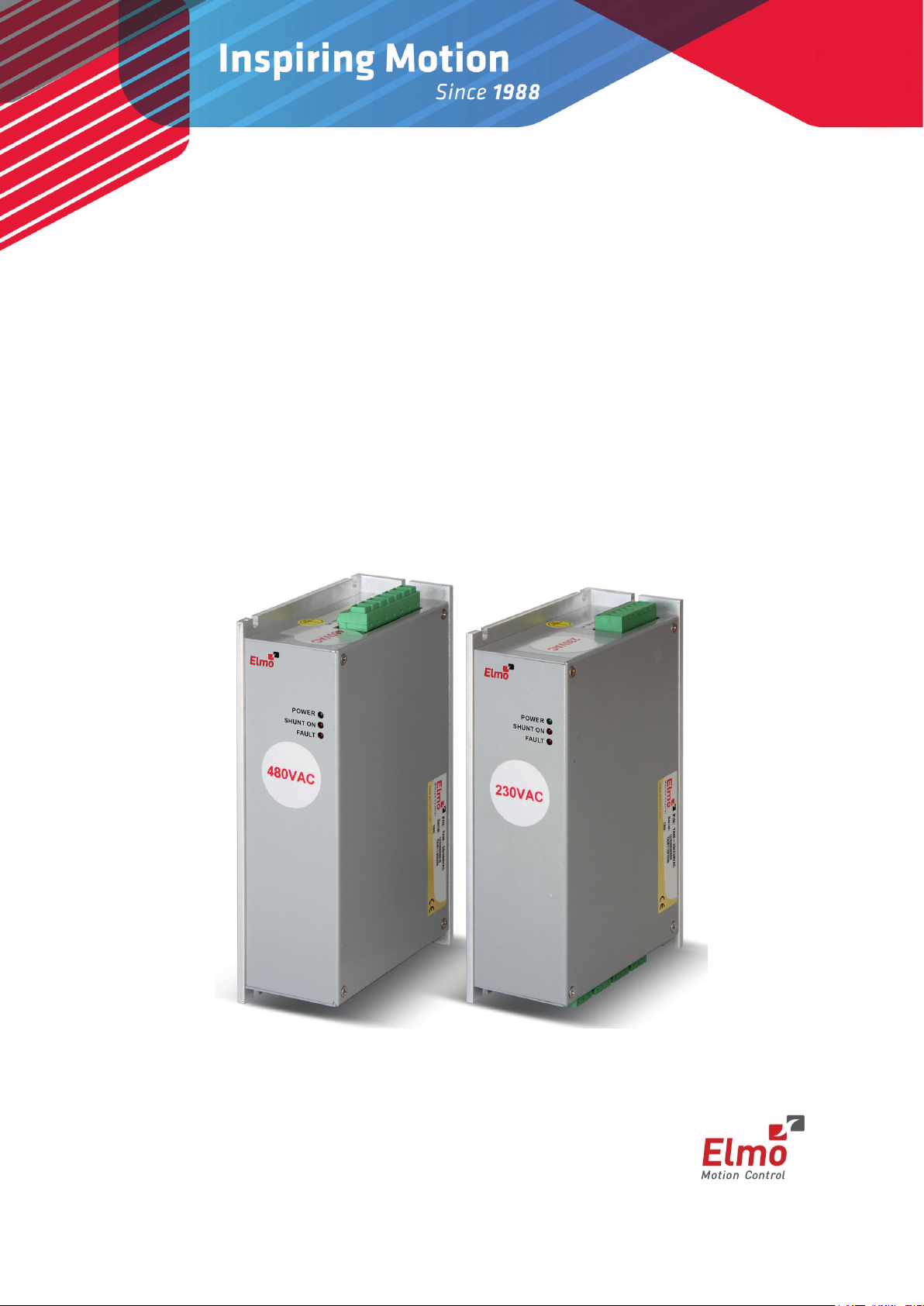
480VAC Model 230VAC Model
June 2014 (Ver. 1.501) www.elmomc.com
Page 2

Table of Contents
Notice
This guide is delivered subject to the following conditions and restrictions:
• This guide contains proprietary information belonging to Elmo Motion Control Ltd. Such
information is supplied solely for the purpose of assisting users of the Tambourine 20 power
supply in its installation.
• The text and graphics included in this manual are for the purpose of illustration and reference
only. The specifications on which they are based are subject to change without notice.
• Information in this document is subject to change without notice.
Document no. MAN-TAMIG (Ver. 1.501)
Copyright 2014
Elmo Motion Control Ltd.
All rights reserved.
Catalog Number
|Warnings|www.elmomc.com
Page 3

Table of Contents
Revision History
Version Release Date Changes/Remarks
1.0 February 2011
1.1 July 2011 Replaced figure on Section 3.4.7
1.2 Sep 2011 Addition of Warnings and Cautions sections, Electrical and Mechanical
1.3 Jan 2012 Added two tables to section 1.1 regarding remnant charge after power
1.4 July 2012 Changes to overvoltage and shunt on pages 8, 11
1.401 February 2013 AC Input frequency Range added
1.402 February 2013 AC Input frequency changed to 20 to 500 Hz
1.500 March 2014 Added Section 3.5: Heat Dissipation
1.501 June 2014 Document update
Initial Release
specifications, and Mounting conditions.
off.
New document template
|Warnings|www.elmomc.com
Page 4

Table of Contents
Table of Contents
MAN-TAMIG (Ver. 1.501)
Chapter 1: Operating Safely .......................................................................................... 6
1.1 Warnings .................................................................................................................... 7
1.2 Cautions ...................................................................................................................... 7
1.3 Directives and Standards ............................................................................................ 8
1.4 CE Mark Conformance ................................................................................................ 8
1.5 Warranty Information ................................................................................................ 8
Chapter 2: Product Description ..................................................................................... 9
2.1 Standard Features .................................................................................................... 10
2.2 Fault Protection ........................................................................................................ 10
2.3 Technical Specifications............................................................................................ 10
2.3.1 Dimensions ................................................................................................ 11
2.3.1.1 Housing of the 36 VAC up to 230 VAC Models ......................... 11
2.3.1.2 Housing of 420 VAC up to 480 VAC Models ............................. 11
2.3.2 Electrical and Mechanical Specifications ................................................... 12
2.3.3 Shunt Regulator ......................................................................................... 13
4
Chapter 3: Installation ................................................................................................ 14
3.1 Before You Begin ...................................................................................................... 14
3.1.1 Site Requirements ..................................................................................... 14
3.1.2 Hardware Requirements ........................................................................... 14
3.1.2.1 AC Input Requirements ............................................................ 14
3.1.2.2 Recommended Wire Cross-Sections (All Models) .................... 14
3.2 Unpacking the Components ..................................................................................... 15
3.3 Connectors ............................................................................................................... 16
3.3.1 Connector Types for 36 VAC up to 230 VAC Models ................................. 16
3.3.2 Connector Types for 420 VAC up to 480 VAC Models ............................... 17
3.3.3 Main AC Input Power Connector Pinout ................................................... 18
3.3.4 4x DC-Output Connector Pinout ................................................................ 19
3.4 Mounting and Wiring the Tambourine 20 ............................................................... 20
3.4.1 Mounting ................................................................................................... 20
3.4.2 Wiring Guidelines ...................................................................................... 20
3.4.3 AC Power Source ....................................................................................... 21
3.4.4 Direct-to-Mains (No Isolation Transformer) Wiring Diagrams .................. 22
3.4.5 Isolated AC Supplies (with an Isolation Transformer) Wiring Diagrams ... 24
3.4.6 Connecting the Main Power Cable ............................................................ 26
3.4.7 Connecting the DC Output Cable .............................................................. 27
3.4.8 DC-Link Shared Connection ....................................................................... 28
3.5 Heat Dissipation ....................................................................................................... 29
3.5.1 Tambourine 20 Thermal Data.................................................................... 29
3.5.2
Heat Dissipation Data ................................................................................ 29
3.5.3 How to Use the Charts ............................................................................... 30
|Warnings|www.elmomc.com
Page 5

Table of Contents
Table of Contents
MAN-TAMIG (Ver . 1.501)
Chapter 4: Initialization .............................................................................................. 31
4.1 LED Diagnostics ........................................................................................................ 31
5
|Warnings|www.elmomc.com
Page 6
Tambourine 20 Power Supply Installation Guide
Table of Contents
Chapter 1:
Operating Safely
Warning:
Caution:
MAN-TAMIG (Ver . 1.501)
6
In order to operate the Tambourine 20 power supply safely, it is imperative that you implement the
safety procedures included in this installation guide. This information is provided to protect you and
to keep your work area safe when using the Power Supply.
Please read this chapter carefully, before you begin the installation process.
Before you start, make sure that all system components are connected to earth ground. Electrical
safety is provided through a low-resistance earth connection.
Only qualified personnel may install, adjust, maintain and repair the product. A qualified person has
the knowledge and authorization to perform tasks such as transporting, assembling, installing,
commissioning and operating power-supplies, drives and motors.
The Tambourine 20 power supply contains electrostatic-sensitive components that can be damaged
if handled incorrectly. To prevent any electrostatic damage, avoid contact with highly insulating
materials, such as plastic film and synthetic fabrics. Place the product on a conductive surface and
ground yourself in order to discharge any possible static electricity build-up.
To avoid any potential hazards that may cause severe personal injury or damage to the product
during operation, keep all covers and cabinet doors shut.
The following safety symbols are used in this manual:
This information is needed to avoid a safety hazard, which might cause bodily
injury.
This information is necessary for preventing damage to the product or to other
equipment.
|Warnings|www.elmomc.com
Page 7
Tambourine 20 Power Supply Installation Guide
Table of Contents
MAN-TAMIG (Ver . 1.501)
1.1 Warnings
• To avoid electric arcing and hazards to personnel and electrical contacts, never
connect/disconnect the Tambourine 20 power supply while the power source is on.
• Disconnect the Tambourine 20 power supply from all voltage sources before it is opened for
servicing.
• The Tambourine 20 power supply contains grounding conduits for electric current protection.
Any disruption to these conduits may cause the instrument to become hot (live) and
dangerous.
• After shutting off the power and removing the power source from your equipment, wait as
described in the tables below, before touching or disconnecting parts of the equipment that
are normally loaded with electrical charges (such as capacitors or contacts). It is recommended
to measure the electrical contact points with a DVM before touching the equipment.
T.P # Function Ref. Results
7
1 Discharge time with no load VP+, VN-
2 Discharge time while the TAM is connected to Elmo
VP+, VN-
~90 sec
~80 sec
drive at MO=0
3 Discharge time with maximum load up to 20 A VP+, VN-
~120 ms
Table 1: 230 VAC Model 1
T.P # Function Ref. Results
1 Discharge time with no load VP+, VN-
2 Discharge time while the TAM is connected to Elmo
VP+, VN-
~45 sec
~40 sec
drive at MO=0
3 Discharge time with maximum load up to 20 A VP+, VN-
~60 ms
Table 2: 480 VAC Model 2
1.2 Cautions
• The Tambourine 20 power supply contains hot surfaces and electrically charged components
during operation.
• The maximum AC/DC power supply connected to the instrument must comply with the
parameters outlined in this guide.
• Before switching on the Tambourine 20 power supply, verify that all safety precautions have
been observed and that the installation procedures in this manual have been followed.
|Warnings|www.elmomc.com
Page 8

Tambourine 20 Power Supply Installation Guide
Table of Contents
MAN-TAMIG (Ver . 1.501)
1.3 Directives and Standards
The Tambourine 20 power supply conforms to the following industry safety standards:
Safety Standard Item
UL 508C Recognized Power Conversion Equipment
In compliance with UL 840 Insulation Coordination, Including Clearance and
Creepage Distances of Electrical Equipment
8
In compliance with UL 60950-1
(formerly UL 1950)
IEC/EN 61800-5-1 approved
Safety of Information Technology Equipment,
Including Electrical Business Equipment
Safety for adjustable speed electrical power drive
system
IEC/EN 61800-3 approved
EMC for adjustable speed electrical power drive
system
In compliance with EN 60204-1 Low Voltage Directive, 73/23/EEC
The Tambourine 20 power supply has been developed, produced, tested and documented in
accordance with the relevant standards. Elmo Motion Control is not responsible for any deviation
from the configuration and installation described in this documentation. Furthermore, Elmo is not
responsible for the performance of new measurements or ensuring that regulatory requirements
are met.
1.4 CE Mark Conformance
The Tambourine 20 power supply is intended for incorporation in a machine or end product. The
actual end product must comply with all safety aspects of the relevant requirements of the
European Safety of Machinery Directive 98/37/EC as amended, and with those of the most recent
versions of standards EN 60204-1 and EN 292-2 at the least.
According to Annex III of Article 13 of Council Directive 93/68/EEC, amending Council Directive
73/23/EEC concerning electrical equipment designed for use within certain voltage limits, the
Tambourine 20 power supply meets the provisions outlined in Council Directive 73/23/EEC. The
party responsible for ensuring that the equipment meets the limits required by EMC regulations is
the manufacturer of the end product.
1.5 Warranty Information
The products covered in this manual are warranted to be free of defects in material and
workmanship and conform to the specifications stated either within this document or in the
product catalog description. All Elmo drives are warranted for a period of 12 months from the time
of installation, or 18 months from time of shipment, whichever comes first. No other warranties,
expressed or implied — and including a warranty of merchantability and fitness for a particular
purpose — extend beyond this warranty.
|Directives and Standards|www.elmomc.com
Page 9
Tambourine 20 Power Supply Installation Guide
Table of Contents
Chapter 2:
Product Description
MAN-TAMIG (Ver . 1.501)
9
The Tambourine 20 power supply is a compact direct-to-mains power supply designed to power
multiple servo drives up to 528 VAC. It was designed to complement Elmo servo drives that do not
include an integrated power supply. It has the following features:
• Rectifies AC input voltages of up to 3×528 VAC into filtered DC voltage with an output current
of 20 A continuous and a 40 A peak.
• The number of servo drives powered by a single Tambourine 20 power supply is limited only
by the total power consumption of the servo drives and not by the output current of the
Tambourine 20.
• Can operate directly from the mains when feeding isolated servo drives, or via an isolation
transformer when non- isolated servo drives are employed.
• Has a high capacitance to offer a low output voltage drop while operating from a single-phase
source.
• Has regenerating braking capability that enables fast braking of high inertia.
• Has built-in inrush current limiters that limit the power-on currents to low levels, reducing
turn-on stress from the mains.
• Has internal EMC filtering that eliminates the necessity for external devices, therefore
complies with CE and other EMC regulations.
• Has a Book Shelf (Panel Mount) structure, enabling simple and fast mounting.
|Warranty Information|www.elmomc.com
Page 10
Tambourine 20 Power Supply Installation Guide
Table of Contents
MAN-TAMIG (Ver . 1.501)
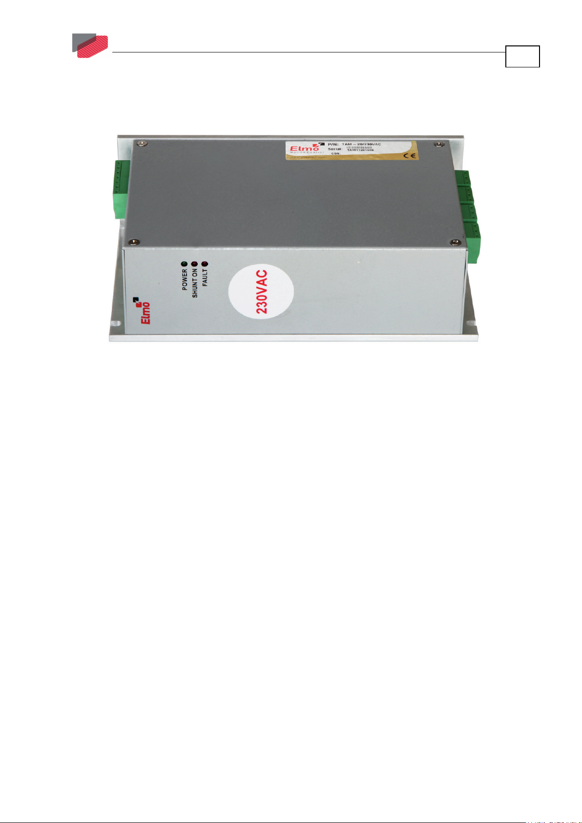
2.1 Standard Features
• 20 A continuous output current
• AC input 20 to 500 Hz
• Single- or three-phase operation
• Direct-to-mains operation capability
• High regenerative (braking) capability
• Inrush current limit
• EMC filtering “inside”
• UL, CE, compliant
2.2 Fault Protection
The Tambourine 20 power supply power supply includes a duty cycle limiter, which inhibits shunt
whenever On and Off time exceeds 2%. This feature protects the shunt regulator when high-inertia
loads are driven by the servo drive(s) or when too high AC voltage is applied to the power supply
(i.e. DC output is already above the threshold of the shunt).
10
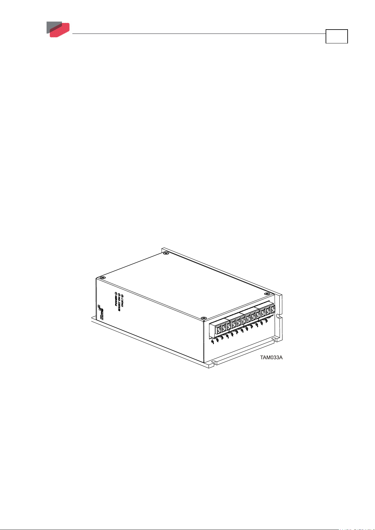
2.3 Technical Specifications
Figure 1: Tambourine 20 Power Supply
|Standard Features|www.elmomc.com
Page 11

Tambourine 20 Power Supply Installation Guide
Table of Contents
MAN-TAMIG (Ver . 1.501)
2.3.1 Dimensions
2.3.1.1 Housing of the 36 VAC up to 230 VAC Models
11
2.3.1.2 Housing of 420 VAC up to 480 VAC Models
|Technical Specifications|www.elmomc.com
Page 12

Tambourine 20 Power Supply Installation Guide
Table of Contents
MAN-TAMIG (Ver . 1.501)
2.3.2 Electrical and Mechanical Specifications
12
Power Supply TAM-20/36VAC TAM-20/60VAC TAM-
20/120VAC
Nominal
Input AC Voltage
20 to 500 Hz
Max
Input AC Voltage
Max Output
Power Cont.
Max Output
Power Peak
Nominal DC bus
Output
(at nominal AC
Voltage)
Shunt Power
(Peak)
DC Output Cont.
Current
1×36 VAC
3×36 VAC
1×38 VAC (L-N)
3×38 VAC (L-L)
1100 W 1800 W 3800 W 7600 W 13000 W 14000 W
2200 W 3600 W 7600 W 15200 W 26000 W 28000 W
50 VDC 85 VDC 170 VDC 325 VDC 560 VDC (for
1.8 kW 4.5 kW 5.5 kW 6 KW 5.5 kW 6.7 kW
20 A 20 A 20 A 20 A 20 A 20 A
1×60 VAC
3×60 VAC
1×61 VAC (L-N)
3×61 VAC (L-L)
1×120 VAC
3×120 VAC
1×131 VAC (L-N)
3×131 VAC (L-L)
TAM20/230VAC
1×230 VAC
3×230 VAC
1×270 VAC (L-N)
3×270 VAC (L-L)
TAM20/420VAC
3×420 VAC 3×480 VAC
3×470 VAC (L-L) 3×528 VAC (L-L)
400 VAC)
594 VDC (for
420 VAC)
TAM20/480VAC
560 VDC (for
400 VAC)
678 VDC (for
480 VAC)
DC Output Peak
Current
Mating Drives XXX-YY/60 XXX-YY/100 XXX-YY/200 XXX-YY/400 XXX-YY/700 XXX-YY/800
Weight 1155 gr 1155 gr 1155 gr 1155 gr 1155 gr 1155 gr
40 A 40 A 40 A 40 A 40 A 40 A
Table 3: Tambourine 20 Electrical Specifications
|Technical Specifications|www.elmomc.com
Page 13

Tambourine 20 Power Supply Installation Guide
Table of Contents
MAN-TAMIG (Ver . 1.501)
2.3.3 Shunt Regulator
A shunt regulator is included in the power supply section of the Tambourine 20. The shunt regulator
is a switching type, wherein dissipative elements (resistors) are switched across the DC bus,
whenever the voltage reaches a predetermined level. The function of the shunt regulator is to
regulate the voltage of the DC bus during the period of motor deceleration, when there is a net
energy outflow from the motor to the servo drive. The servo drive handles this reverse energy just
as efficiently as it provides energy to the motor, hence, most of the energy is passed through the
servo drive back to the power supply, where this returning energy charges the filter capacitors
above their normal voltage level, as determined by the AC incoming voltage.
When the capacitors charge-up reaches the predetermined shunt threshold level, the shunt
regulator begins its regulating action. The bus is regulated to the specific model type voltage, until
regeneration ceases.
13
|Technical Specifications|www.elmomc.com
Page 14

Tambourine 20 Power Supply Installation Guide
Table of Contents
Chapter 3:
Installation
MAN-TAMIG (Ver . 1.501)
14
This chapter describes the installation of the Tambourine 20 power supply.
3.1 Before You Begin
3.1.1 Site Requirements
You can guarantee the safe operation of the Tambourine 20 by ensuring that it is installed in an
appropriate environment.
Feature Value
Ambient operating temperature 0 °C to 40 °C (32 °F to 104 °F)
Maximum non-condensing humidity 90%
Operating area atmosphere No flammable gases or vapors permitted in area
Models for extended environmental conditions are available.
Caution
operating temperature of 0 °C to 40 °C (32 °F to 104 °F) must not be exceeded.
: The Tambourine 20 dissipates its heat by convection. The maximum ambient
3.1.2 Hardware Requirements
3.1.2.1 AC Input Requirements
Circuit Breakers &
Contacts
Circuit breaker current rating 32 A Type D 40 A Type D
Circuit breaker voltage rating 250 VAC / 480 VAC depending upon operating AC voltage
Contactor 32 A 40 A
3.1.2.2 Recommended Wire Cross-Sections (All Models)
Feature Connection Details
AC input AC1, AC2, AC3 2.5 mm2, 12 AWG
DC Output VP+, VN- 2.5 mm2, 12 AWG
Protective earth PE 2.5 mm2, 12 AWG
Three-Phase Supply
Voltage
Single-Phase Supply
Voltage
|Before You Begin|www.elmomc.com
Page 15

Tambourine 20 Power Supply Installation Guide
Table of Contents
MAN-TAMIG (Ver . 1.501)
3.2 Unpacking the Components
To unpack the Tambourine 20:
1. Carefully remove the power supply from the box and Styrofoam.
2. Check the product to ensure that there is no visible damage. If any damage has occurred, report
immediately to the carrier that delivered your product.
3. To ensure that the Tambourine 20 you have unpacked is the appropriate type for your
requirements, locate the part number sticker on the product.
The Part number provides the type designation.
15
4. Verify that the Tambourine 20 model is the one you ordered, and ensure that the voltage meets
your specific requirements.
|Unpacking the Components|www.elmomc.com
Page 16

Tambourine 20 Power Supply Installation Guide
Table of Contents
MAN-TAMIG (Ver . 1.501)
3.3 Connectors
3.3.1 Connector Types for 36 VAC up to 230 VAC Models
The Tambourine 20 is delivered with the following external mating connectors:
No. Pins Type Function
16
Input Connector x1
1 × 7 pins Phoenix P/N 1911907
(MSTB 2,5HC/7-ST)
Output Connectors x4
Main AC Input
4 × 3 pins Phoenix P/N 1911868
(MSTB 2,5HC/3-ST)
Table 4: Connector Types for 36 VAC up to 230 VAC Models
DC Outputs
|Connectors|www.elmomc.com
Page 17

Tambourine 20 Power Supply Installation Guide
Table of Contents
MAN-TAMIG (Ver . 1.501)
3.3.2 Connector Types for 420 VAC up to 480 VAC Models
The Tambourine 20 is delivered with the following external mating connectors:
No. Pins Type Function
17
Input Connector x1
1 × 7 pins Phoenix P/N 1714320
(GMSTB 2,5HCV/7-ST-7,62)
Output Connectors x4
4 × 3 pins Phoenix P/N 1714281
(GMSTB 2,5HCV/3-ST-7,62)
Main AC Input
DC Outputs
Table 5: Connector Types for 420 VAC up to 480 VAC Models
|Connectors|www.elmomc.com
Page 18

Tambourine 20 Power Supply Installation Guide
Table of Contents
TAM014A
MAN-TAMIG (Ver . 1.501)
3.3.3 Main AC Input Power Connector Pinout
Refer to section 3.4.6 for details of the connections.
Terminal Function Cable
AC1 AC Input phase #1 AC input
AC1 AC Input phase #1 AC input
AC2 AC Input phase #2 AC input
AC2 AC Input phase #2 AC input
AC3 AC Input phase #3 AC input
AC3 AC Input phase #3 AC input
PE Protective Earth AC input
18
Table 6: Main AC Input Connector Pinout
|Connectors|www.elmomc.com
Page 19

Tambourine 20 Power Supply Installation Guide
Table of Contents
MAN-TAMIG (Ver . 1.501)
3.3.4 4x DC-Output Connector Pinout
Refer to section 3.4.7 for details of the connections.
Terminal Function Cable
VP+ Positive Power output DC output cable to a drive
VN- Negative Power output DC output cable to a drive
PE Protective earth DC output cable to a drive
19
Table 7: DC- Output Connector to Drive Pinout
|Connectors|www.elmomc.com
Page 20

Tambourine 20 Power Supply Installation Guide
Table of Contents
MAN-TAMIG (Ver . 1.501)
3.4 Mounting and Wiring the Tambourine 20
For optimum heat dissipation, the Tambourine 20 should be installed with the heat sink attached to
the machine's chassis. When mounting the Tambourine 20 make sure to leave about 1 cm (0.4“)
outward from the heatsink, to enable free air convection around the power supply.
3.4.1 Mounting
20
Figure 2: Mounting the Tambourine 20
The Tambourine 20 is designed for two standard mounting options (Figure 2):
• Wall Mount along the back (can also be mounted horizontally on a metal surface)
• Book Shelf along the side
1. Use M4 x 8 round head screws, one through each opening in the heat sink, to mount the
Tambourine 20 in position opposite the specific holes drilled.
2. Tighten the screws to just tight. Do not overtighten the screws.
3.4.2 Wiring Guidelines
1. Use flexible wires with the proper cross-section to handle the unit current. Color coding is
recommended.
2. After the wiring is completed, carefully inspect all connections in order to ensure tightness.
|Mounting and Wiring the Tambourine 20|www.elmomc.com
Page 21

Tambourine 20 Power Supply Installation Guide
Table of Contents
TAMBOURINE VP+ Output Derating vs. Load current
100%
95%
92%
89%
85%
0%
10%
20%
30%
40%
50%
60%
70%
80%
90%
100%
110%
0 3 5 8 10 13 15
18 20
Load Current [A]
VP+ Output [%]
MAN-TAMIG (Ver . 1.501)
3.4.3 AC Power Source
The AC voltage supply can be of any voltage within the range defined in the Tambourine 20
technical specifications. It must be able to deliver power to the servo drives (including peak power),
without significant drops. A three-phase supply is always recommended whenever possible, in
order to provide better DC bus voltage stability (low voltage ripple) under high load conditions.
Inrush current control is included within the Tambourine 20 power supply, which makes the
Tambourine 20 capable to be fed directly from the mains, whenever it supplies isolated drives.
When operating with a single-phase supply, a voltage drop due to loading is expected. The
magnitude of the voltage drop depends on the load current and the stiffness of the power source.
The following is a graph showing the typical expected VP+ drop, at certain load current when
supplied by a single AC phase source:
21
|Mounting and Wiring the Tambourine 20|www.elmomc.com
Page 22

Tambourine 20 Power Supply Installation Guide
Table of Contents
MAN-TAMIG (Ver . 1.501)
3.4.4 Direct-to-Mains (No Isolation Transformer) Wiring Diagrams
Figure 3: Single-Phase Direct-to-Mains Connection
22
Caution
together in a shared connection.
: When using a single-phase AC source, terminals AC2 and AC3 must be paired
Figure 4: Three-Phase Direct-o-Mains Connection
|Mounting and Wiring the Tambourine 20|www.elmomc.com
Page 23

Tambourine 20 Power Supply Installation Guide
Table of Contents
MAN-TAMIG (Ver . 1.501)
23
Figure 5: Multiple Direct-to-Mains Connection
|Mounting and Wiring the Tambourine 20|www.elmomc.com
Page 24

Tambourine 20 Power Supply Installation Guide
Table of Contents
MAN-TAMIG (Ver . 1.501)
3.4.5 Isolated AC Supplies (with an Isolation Transformer) Wiring
Diagrams
Figure 6: Single-Phase Isolated Source Connection
24
Caution:
• When using a single-phase AC source, terminals AC2 and AC3 must be paired
together in a shared connection.
• When using an isolation transformer, PR and PE must be connected together on the
Tambourine 20 side.
Figure 7: Three-Phase Isolated Source Connection
Caution
on the Tambourine 20 side.
: When using an isolation transformer, PR and PE must be connected together
|Mounting and Wiring the Tambourine 20|www.elmomc.com
Page 25

Tambourine 20 Power Supply Installation Guide
Table of Contents
MAN-TAMIG (Ver . 1.501)
25
Figure 8: Multiple Isolated Source Connection
All wiring guidelines for supply connections described previously apply to multiple-Tambourine 20
connections.
|Mounting and Wiring the Tambourine 20|www.elmomc.com
Page 26

Tambourine 20 Power Supply Installation Guide
Table of Contents
MAN-TAMIG (Ver . 1.501)
3.4.6 Connecting the Main Power Cable
To connect the AC power cable:
1. For best noise immunity, a shielded (not twisted) cable is recommended (not mandatory) for
the AC input cable.
2. When operating with a three-phase power source, a 4-wire shielded cable should be used:
a. Connect the 3-phase leads of the main input cable to the AC1, AC2 and AC3 terminals of the
main input connector.
26
b. For safety requirements, the green/yellow-wire must be connected to the protective earth
(PE terminal). Connect the Protective Earth wire to the PE terminal on the main input
connector.
When operating with a single-phase power source, a 3-wire shielded cable should be used:
a. Connect the first phase lead of the main input cable to the AC1 terminal of the main input
connector.
For an output of 1 to 10 A:
The second lead can be connected into either terminal AC2 or AC3.
For an output of 10 A and higher:
The second lead must be connected into both terminal AC2 and AC3.
b. For safety requirements, the green/yellow-wire must be connected to the protective earth
(PE terminal). Connect the Protective Earth wire to the PE terminal on the main input
connector.
3. The gauge of the cable strands is determined by:
a. For three-phase source, the sum of the actual current consumption of the drives being fed
by the Tambourine 20.
b. For single-phase source, twice the sum of the actual current consumption of the drives
being fed by the Tambourine 20.
4. The Tambourine 20 has a dual-terminal input for each phase. Whenever the total output-
current from the Tambourine 20 exceeds 10 A – each input phase MUST be connected through
both twin-terminals.
|Mounting and Wiring the Tambourine 20|www.elmomc.com
Page 27

Tambourine 20 Power Supply Installation Guide
Table of Contents
MAN-TAMIG (Ver . 1.501)
3.4.7 Connecting the DC Output Cable
To connect the DC output cable:
1. For best noise immunity, a shielded and twisted cable is recommended (not mandatory) for the
DC output cable. A 3-wire shielded cable should be used. The gauge is determined by the actual
current consumption of the drives being fed by the relevant DC output.
2. Connect the three wires of the DC output cable to the DC output connector of the
Tambourine 20:
a. Connect the DC leads to the VP+ and VN- terminals of the DC output connector.
27
b. For safety requirements, the third green/yellow-wire must be connected to the protective
earth (PE terminal). Connect the Protective Earth wire to the PE terminal on the DC output
connector.
3. When the Tambourine 20 is fed from an isolation transformer, from the safety and EMI aspects,
the PR (VN-) junction must be connected to PE junction.
|Mounting and Wiring the Tambourine 20|www.elmomc.com
Page 28

Tambourine 20 Power Supply Installation Guide
Table of Contents
MAN-TAMIG (Ver . 1.501)
3.4.8 DC-Link Shared Connection
Each Tambourine 20 contains a shunt. Its purpose is to "absorb" regenerated energy created by the
motor during braking and convert that energy into heat. If the energy regenerated by the motor
exceeds the capacity of the shunt, the drive is inhibited and an overvoltage message is sent.
To prevent this from happening, the braking-capacity of the shunt system can be extended by
connecting the DC output of several Tambourine 20s in parallel. When two or more Tambourine 20s
are connected, by DC Link cables, the regenerated energy is distributed among them. This spreads
the energy spikes over several shunts and enables the application to continue normal operation,
and avoid overvoltage interruptions.
28
Figure 9: The Tambourine 20's External DC Link Option
Caution: Tambourine 20 1 and Tambourine 20 2 must have an identical voltage
rating.
|Mounting and Wiring the Tambourine 20|www.elmomc.com
Page 29

Tambourine 20 Power Supply Installation Guide
Table of Contents
MAN-TAMIG (Ver . 1.501)
3.5 Heat Dissipation
For full power output capability the Tambourine 20 is designed to be mounted on an external heatsink. It is highly recommended that the “Wall” on which the Tambourine 20 is mounted will have
heat dissipation capabilities. The Tambourine 20 at “free air convection” (without an additional
heat-sink) can dissipate around 12 W for 40°C ambient temperature and not exceeding 85 °C on the
heat sink.
When “Free Air Convection” is sufficient for the application it is recommended to leave
approximately 10 mm of space between the Tambourine 20's heat sink and any other assembly.
When attaching to an external heat-sink, it is recommended to use N5-N7 surface treatment and
thermal foil or smearing thermal compound.
3.5.1 Tambourine 20 Thermal Data
• Free air convection thermal resistance (θ): Approximately 5 to 6°C/W.
• Thermal time constant: Approximately 20 minutes/ 1200 seconds (thermal time constant
means that the Tambourine 20 will reach 2/3 of its final temperature after 20 minutes).
29
• Self-heat dissipation capability (no external heat sink): 12 W for 40°C/W temperature rise.
• The thermal resistance when connecting to an external heat sink using a thermal conductive
compound/foil. By proper smearing of the surface a significant improvement of the thermal
resistance is achieved: 0.03°C/W.
3.5.2 Heat Dissipation Data
Heat Dissipation is shown graphically below:
Figure 10: Dissipation versus Current Graph
|Heat Dissipation|www.elmomc.com
Page 30

Tambourine 20 Power Supply Installation Guide
Table of Contents
MAN-TAMIG (Ver . 1.501)
3.5.3 How to Use the Charts
The charts above are based upon theoretical worst-case conditions. Actual test results show 30% to
50% better power dissipation.
To determine if your application needs a heat sink:
1. Allow maximum heat sink temperature to be 85 °C or less.
2. Determine the ambient operating temperature of the Tambourine 20 as ≤ 40°C.
3. Calculate the allowable temperature increase according to the following example: For an
ambient temperature of 40 °C, ΔT = 85 to 40°C = 45°C
4. Use the chart to find the actual dissipation power of the drive. Follow the curve to the desired
output current and then find the dissipated power.
30
|Heat Dissipation|www.elmomc.com
Page 31

Tambourine 20 Power Supply Installation Guide
Table of Contents
Chapter 4:
Initialization
MAN-TAMIG (Ver . 1.501)
31
4.1 LED Diagnostics
Figure 11: Power LED Indicators
The following indication LEDs are mounted on the front panel of the Tambourine 20 (Figure 11):
LED Color Indication
POWER Green Internal supply presence
SHUNT ON Red Shunt is on (blinks whenever the shunt is activated)
FAULT Red Shunt is inhibited due to:
A DC bus level that is higher than the shunt
threshold point
A duty cycle limitation
Wait a couple of minutes to exit the fault state.
The LED will switch OFF. Then reinitialize the system.
|LED Diagnostics|www.elmomc.com
 Loading...