

Page 1

Tambourine 100
Power Supply Installation
Guide
January 2014 (Ver. 1.101) www.elmomc.com
Page 2
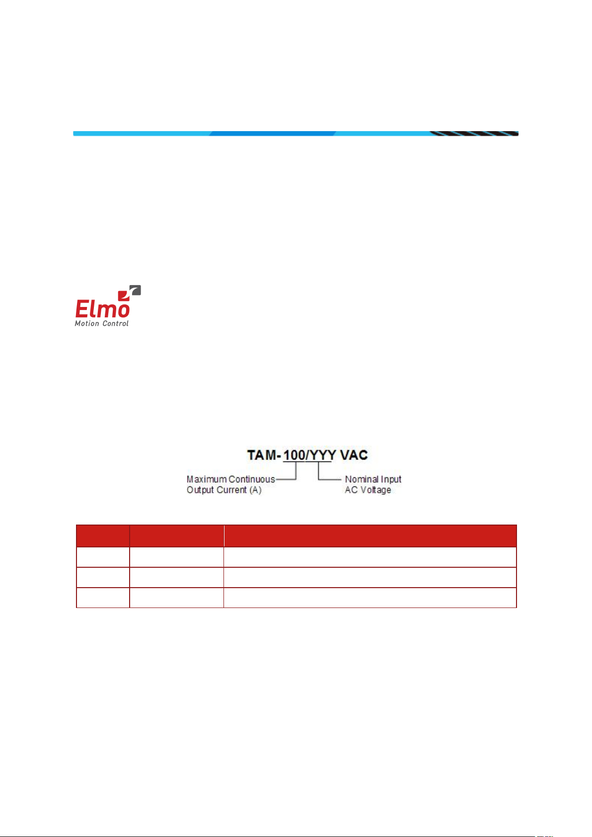
Table of Contents
Elmo Motion Control and the Elmo Motion Control logo are registered
Notice
This guide is delivered subject to the following conditions and restrictions:
This guide contains proprietary information belonging to Elmo Motion Control Ltd.
Such information is supplied solely for the purpose of assisting users of the
Tambourine 100 power supply in its installation.
The text and graphics included in this manual are for the purpose of illustration and
reference only. The specifications on which they are based are subject to change
without notice.
Information in this document is subject to change without notice.
trademarks of Elmo Motion Control Ltd.
Document no. MAN-TAM-100IG (Ver. 1.101)
Catalog Number
Revision History
Version Release Date Changes/Remarks
1.0 April 2012 Initial Release
1.1 Jan 2013 Updated
1.101 Jan 2014 Updated Format and table section 1.1
Copyright 2014
Elmo Motion Control Ltd.
All rights reserved.
||www.elmomc.com
Page 3

Table of Contents
Table of Contents
MAN-TAM-100IG (Ver. 1.101)
Chapter 1: Operating Safely .............................................................................................. 4
1.1. Warnings .................................................................................................................... 5
1.2. Cautions ...................................................................................................................... 5
1.3. Directives and Standards ............................................................................................ 6
1.4. CE Mark Conformance ................................................................................................ 6
1.5. Warranty Information ................................................................................................ 6
Chapter 2: Product Description ......................................................................................... 7
1.6. Standard Features ...................................................................................................... 8
1.7. Protection ................................................................................................................... 8
1.8. Technical Specifications.............................................................................................. 9
1.8.1. Dimensions .................................................................................................. 9
1.8.2. Electrical and Mechanical Specifications ................................................... 10
1.8.3. Shunt Regulator ......................................................................................... 10
3
Chapter 3: Installation .................................................................................................... 11
1.9. Site Requirements .................................................................................................... 11
1.10. Hardware Requirements .......................................................................................... 11
1.1.1.1. AC Input Requirements ............................................................ 11
1.1.1.2. Recommended Wire Cross-Sections (All Models) .................... 11
1.11. Unpacking the Components ..................................................................................... 12
1.12. Connectors ............................................................................................................... 13
1.12.1. Connector Types ........................................................................................ 13
1.12.2. Main AC Input Power Connector Pinout ................................................... 15
1.12.3. 5x DC-Output Connectors Pinout .............................................................. 15
1.13. I/O Port ..................................................................................................................... 16
1.14. Mounting and Wiring the Tambourine 100 ............................................................. 17
1.14.1. Mounting ................................................................................................... 17
1.14.2. Wiring Guidelines ...................................................................................... 18
1.14.3. AC Power Source ....................................................................................... 18
1.14.4. Direct-to-Mains (No Isolation Transformer) Wiring Diagrams .................. 18
1.14.5. Isolated AC Supplies (with an Isolation Transformer) Wiring Diagrams ... 21
1.14.6. Connecting External 24 V DC source to the Control System ..................... 23
1.14.7. Connecting the Main Power Cable ............................................................ 24
1.14.8. Connecting the DC Output Cable .............................................................. 25
Chapter 4: I/O and Diagnostics Initialization ................................................................... 26
1.15. Digital Inputs ............................................................................................................ 26
1.16. Digital Outputs.......................................................................................................... 27
1.17. LED Diagnostics ........................................................................................................ 28
||www.elmomc.com
Page 4

Tambourine 100 Power Supply
Table of Contents
Chapter 1: Operating Safely
Warning:
Caution:
MAN-TAM-100IG (Ver. 1.101)
In order to operate the Tambourine 100 power supply safely, it is imperative that you
implement the safety procedures included in this installation guide. This information is
provided to protect you and to keep your work area safe when using the Power Supply.
Please read this chapter carefully, before you begin the installation process.
Before you start, make sure that all system components are connected to earth ground.
Electrical safety is provided through a low-resistance earth connection.
Only qualified personnel may install, adjust, maintain and repair the product. A qualified
person has the knowledge and authorization to perform tasks such as transporting, assembling,
installing, commissioning and operating power-supplies, drives and motors.
The Tambourine 100 power supply contains electrostatic-sensitive components that can be
damaged if handled incorrectly. To prevent any electrostatic damage, avoid contact with highly
insulating materials, such as plastic film and synthetic fabrics. Place the product on a
conductive surface and ground yourself in order to discharge any possible static electricity
build-up.
4
To avoid any potential hazards that may cause severe personal injury or damage to the product
during operation, keep all covers and cabinet doors shut.
The following safety symbols are used in this manual:
This information is needed to avoid a safety hazard, which might cause
bodily injury.
This information is necessary for preventing damage to the product or to
other equipment.
||www.elmomc.com
Page 5

Tambourine 100 Power Supply
Table of Contents
MAN-TAM-100IG (Ver. 1.101)
1.1. Warnings
To avoid electric arcing and hazards to personnel and electrical contacts, never
connect/disconnect the Tambourine 100 power supply while the power source
is on.
Disconnect the Tambourine 100 power supply from all voltage sources before it
is opened for servicing.
The Tambourine 100 power supply contains grounding conduits for electric
current protection. Any disruption to these conduits may cause the instrument
to become hot (live) and dangerous.
When the Tambourine 100 is connected directly to the Mains, VN- must not be
connected to the PE!
After shutting off the power and removing the power source from your
equipment, wait as described in the tables below, before touching or
disconnecting parts of the equipment that are normally loaded with electrical
charges (such as wires or contacts). It is recommended to measure the electrical
contact points with a DVM before touching the equipment.
5
Function Ref. Results
1 Discharge time with no load VP+, VN- 3 mins
2 Discharge time with more than 20A load VP+, VN- 1 min
Table 1: Safe Discharge Time
1.2. Cautions
The Tambourine 100 power supply contains hot surfaces and electrically charged
components during operation.
The maximum AC/DC power supply connected to the instrument must comply
with the parameters outlined in this guide.
Before switching on the Tambourine 100 power supply, verify that all safety
precautions have been observed and that the installation procedures in this
manual have been followed.
||www.elmomc.com
Page 6

Tambourine 100 Power Supply
Table of Contents
MAN-TAM-100IG (Ver. 1.101)
1.3. Directives and Standards
The Tambourine 100 power supply conforms to the following industry safety standards:
Safety Standard Item
In compliance with UL 508C Power Conversion Equipment
In compliance with UL 840 Insulation Coordination, Including Clearance and
Creepage Distances of Electrical Equipment
6
In compliance with UL 60950-1
(formerly UL 1950)
Safety of Information Technology Equipment,
Including Electrical Business Equipment
In compliance with EN 60204-1 Low Voltage Directive, 73/23/EEC
The Tambourine 100 power supply has been developed, produced, tested and documented in
accordance with the relevant standards. Elmo Motion Control is not responsible for any
deviation from the configuration and installation described in this documentation.
Furthermore, Elmo is not responsible for the performance of new measurements or ensuring
that regulatory requirements are met.
1.4. CE Mark Conformance
The Tambourine 100 power supply is intended for incorporation in a machine or end product.
The actual end product must comply with all safety aspects of the relevant requirements of the
European Safety of Machinery Directive 98/37/EC as amended, and with those of the most
recent versions of standards EN 60204-1 and EN 292-2 at the least.
According to Annex III of Article 13 of Council Directive 93/68/EEC, amending Council Directive
73/23/EEC concerning electrical equipment designed for use within certain voltage limits, the
Tambourine 100 power supply meets the provisions outlined in Council Directive 73/23/EEC.
The party responsible for ensuring that the equipment meets the limits required by EMC
regulations is the manufacturer of the end product.
1.5. Warranty Information
The products covered in this manual are warranted to be free of defects in material and
workmanship and conform to the specifications stated either within this document or in the
product catalog description. All Elmo drives are warranted for a period of 12 months from the
time of installation, or 18 months from time of shipment, whichever comes first. No other
warranties, expressed or implied — and including a warranty of merchantability and fitness for
a particular purpose — extend beyond this warranty.
||www.elmomc.com
Page 7
Tambourine 100 Power Supply
Table of Contents
Chapter 2: Product Description
MAN-TAM-100IG (Ver. 1.101)
7
The Tambourine 100 power supply is a smart and compact three phase direct-to-mains power
supply designed to power multiple servo drives. It was designed to complement Elmo servo
drives that do not include an integrated power supply. It has the following features:
Rectifies AC input voltages of up to 3×528 VAC into filtered DC voltage with an
output current of 100A continuous and a 200 A peak.
The number of servo drives powered by a single Tambourine 100 power supply is
limited only by the total power consumption of the servo drives and not by the
output current of the Tambourine 100. Therefore, a number of servo drives can
be powered by a single Tambourine 100, as long as the total sum of these
drives' power-consumption is below 100A.
Either operates directly from the mains when feeding isolated servo drives or via
an isolation transformer when non- isolated servo drives are employed.
Has regenerating braking capability that enables fast braking of high inertia.
Has built-in active zero crossing inrush current limiters that limit the power-on
currents to low levels, reducing turn-on stress from the mains.
Has internal EMC filtering that eliminates the necessity for external devices,
therefore complies with CE and other EMC regulations.
Has a metallic book shelf (panel mount) structure, enabling simple and fast
mounting.
||www.elmomc.com
Page 8

Tambourine 100 Power Supply
Table of Contents
MAN-TAM-100IG (Ver. 1.101)
1.6. Standard Features
100 A continuous output current
AC input (50 to 500 Hz)
Three-phase operation only
Direct-to-mains operation capability
High regenerative (braking) capability
Active zero crossing inrush current limit
EMC filtering “inside”
Use I/O level to control On/Off output power
UL, CE, compliant
1.7. Protection
8
1.1.1 Shunt duty-cycle limit
The shunt regulator system within the Tambourine 100 power supply includes a duty cycle
limiter, which inhibits the shunt whenever the shunt "On- time" exceeds 1.5% of the
application's repetitive motion-cycle, or when a continuous braking duration of about 500msec
occurs.
1.1.2 Phase Missed Detector Circuit
Phase missed detector circuit which halts the operation of the rectifier bridge, either,
whenever any of the three Mains phases is not present, or when the three phase AC source is
significantly unbalanced. The detector attempts to revive the power supply with a cycle of
about 1 sec.
1.1.3 Levels of Temperature Management
Three levels of temperature management:
st
1
Fan operation occurs at about 70°C.
nd
Digital output – “temperature forewarn alert” occurs at around 75°C.
2
rd
Bridge shutdown occurs at around 85°C.
3
Note :
The integrated Fan is triggered either by the Temperature-sensor located on the Heat sink, or
by the shunt duty-cycle limiter. Once triggered, the Fan will continuously rotate at intervallengths of about 5 minutes each, as long as one of the triggers exists.
||www.elmomc.com
Page 9
Tambourine 100 Power Supply
Table of Contents
MAN-TAM-100IG (Ver. 1.101)
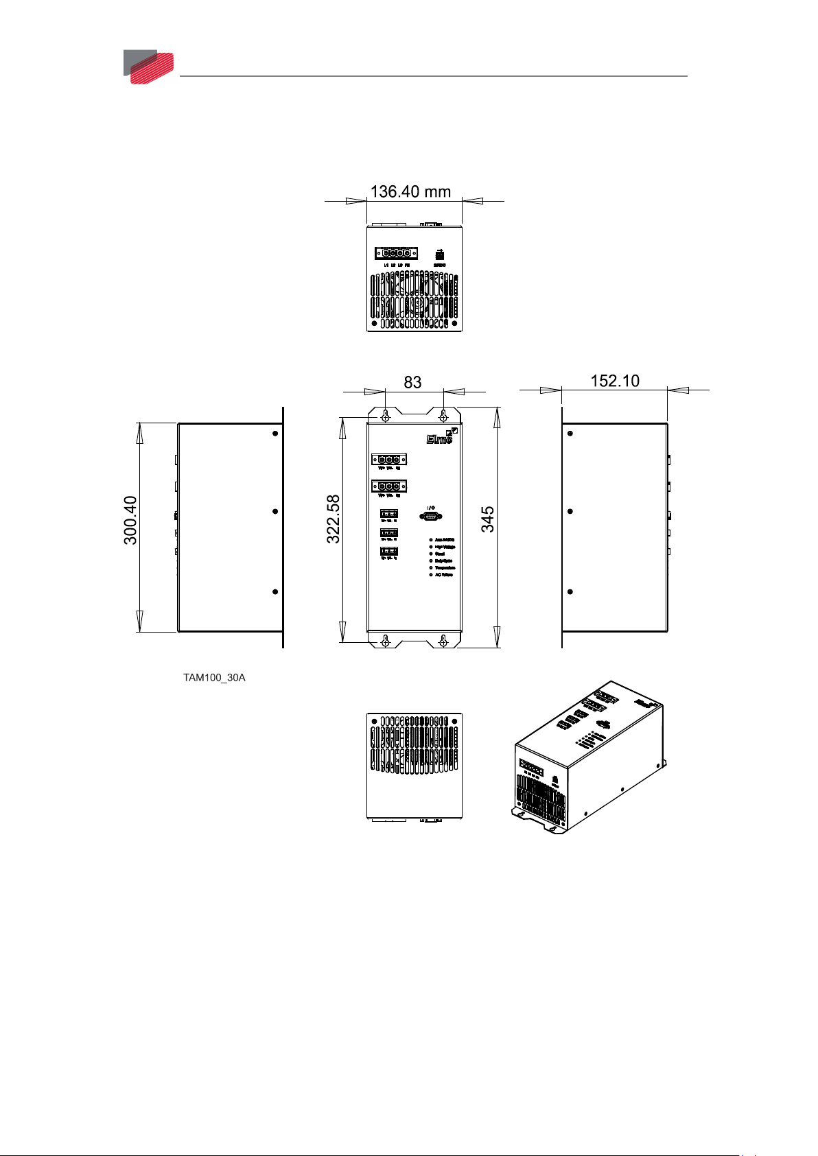
1.8. Technical Specifications
1.8.1. Dimensions
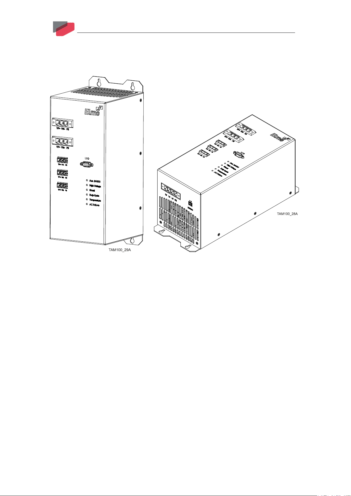
9
Figure 1: Tambourine 100 Power Supply
||www.elmomc.com
Page 10

Tambourine 100 Power Supply
Table of Contents
MAN-TAM-100IG (Ver. 1.101)
1.8.2. Electrical and Mechanical Specifications
Power Supply TAM -100/120VAC TAM -100/230VAC TAM-100/480VAC
10
Nominal
Input AC Voltage
Max
Input AC Voltage
Max Output Power Cont.
Max Output Power Peak
Nominal DC bus Output
(at nominal AC Voltage)
Shunt Power (Peak)
Shunt trip voltage (V)
DC Output Cont. Current
DC Output Peak Current
Mating Drives
Aux Power supply Voltage &
power
Weight
Operating temperature
3X120VAC 3X230VAC 3X480VAC
3X125VAC 3X270VAC 3X528VAC
18KW 38KW 75KW
36KW 76KW 150KW
170 VDC 325 VDC 560VDC for 400VAC input
680VDC for 480VAC input
9KW 11KW 23KW
182 to 189 382 to 386 747 to 758
100A 100A 100A
200A 200A 200A
XXX-YYY/200 XXX-YYY/400
20VDC to 27.5VDC
12W (including fan)
5Kg 5Kg
0˚C to 40˚C 0˚C to 40˚C 0˚C to 40˚C
20VDC to 27.5VDC
12W (including fan)
XXX-YYY/800
20VDC to 27.5VDC
12W (including fan)
5Kg
Table 2: Tambourine 100 Electrical and Mechanical Specifications
1.8.3. Shunt Regulator
A shunt regulator is included in the power supply section of the Tambourine 100. The shunt
regulator is a switching type, wherein dissipative elements (power resistors) are switched
across the DC bus, whenever the voltage reaches a predetermined level. The function of the
shunt regulator is to regulate the voltage of the DC bus during the period of motor
deceleration, when there is a net energy outflow from the motor to the servo drive, to prevent
the servo drive from disabling itself as a result of an “over-voltage" type reason.
When the capacitors charge-up reaches the predetermined shunt threshold level, the shunt
regulator begins its regulating action. The bus is regulated to the specific model type voltage,
until the regeneration-energy is dissipated.
||www.elmomc.com
Page 11

Tambourine 100 Power Supply
Table of Contents
Chapter 3: Installation
MAN-TAM-100IG (Ver. 1.101)
This chapter describes the installation of the Tambourine 100 power supply.
1.9. Site Requirements
You can guarantee the safe operation of the Tambourine 100 by ensuring that it is installed in
an appropriate environment.
Feature Value
Ambient operating temperature 0 °C to 40 °C (32 °F to 104 °F)
Maximum non-condensing humidity 90%
Operating area atmosphere No flammable gases or vapors permitted in area
Models for extended environmental conditions are available.
11
Caution
The Tambourine 100 dissipates its heat by driven fan convection. The maximum ambient
operating temperature of 0 °C to 40 °C (32 °F to 104 °F) must not be exceeded.
Make sure that no cover closes the grids at both ends of the power supply.
:
1.10. Hardware Requirements
1.1.1.1. AC Input Requirements
Circuit Breakers & Contacts Three-Phase Supply Voltage
Circuit breaker current rating 80 A Type C
Circuit breaker voltage rating 250 VAC / 480 VAC depending upon operating AC
voltage
Contactor 80 A
1.1.1.2. Recommended Wire Cross-Sections (All Models)
Feature Connection Details
High Current
(large conn.)
Medium current
(small conn.)
AC input
DC Output
Protective earth
||www.elmomc.com
AC1, AC2, AC3
VP+, VN-
PE
18 to 6 AWG 24 to 14 AWG
18 to 6 AWG 24 to 14 AWG
18 to 6 AWG 24 to 14 AWG
Page 12

Tambourine 100 Power Supply
Table of Contents
MAN-TAM-100IG (Ver. 1.101)
12
1.11. Unpacking the Components
To unpack the Tambourine 100:
1. Carefully remove the power supply from the box and Styrofoam.
2. Check the product to ensure that there is no visible damage. If any damage has occurred,
report immediately to the carrier that delivered your product.
3. To ensure that the Tambourine 100 you have unpacked is the appropriate type for your
requirements, locate the part number sticker on the product.
The Part number provides the type designation.
4. Verify that the Tambourine 100 model is the one you ordered, and ensure that the
voltage meets your specific requirements.
||www.elmomc.com
Page 13

Tambourine 100 Power Supply
Table of Contents
High Current
Medium Current
MAN-TAM-100IG (Ver. 1.101)
1.12. Connectors
1.12.1. Connector Types
The Tambourine 100 is delivered with the following external mating connectors:
No. Pins Type Function
Input Connector x1
13
1 × 4 pins Phoenix P/N 1967472
(PC 16/4-STF-10,16)
Output Connectors x5
High Current Medium Current
2 × 3 pins Phoenix P/N 1967469
(PC 16/3-STF-10,16)
3 × 3 pins Phoenix P/N 1714281
(GMSTB 2.5 HCV/3-ST-7.62)
Main AC Input
High Current DC
Output
Medium Current
DC Output
||www.elmomc.com
Page 14

Tambourine 100 Power Supply
Table of Contents
MAN-TAM-100IG (Ver. 1.101)
No. Pins Type Function
External 24V DC
14
1 × 2 pins Phoenix P/N 1803578
24 V DC Input
(MC 1.5/2-ST-3,81)
I/O Connection
1 x 9 pins D-Type 9-pin Male I/O connector
Table 3: Connector Types
||www.elmomc.com
Page 15

Tambourine 100 Power Supply
Table of Contents
MAN-TAM-100IG (Ver. 1.101)
1.12.2. Main AC Input Power Connector Pinout
Refer to section 3.6.6 for details of the connections.
Terminal Function Cable
L1 AC Input phase #1 AC input
L2 AC Input phase #2 AC input
L3 AC Input phase #3 AC input
PE Protective Earth AC input
15
Table 4: Main AC Input Connector Pinout
1.12.3. 5x DC-Output Connectors Pinout
Refer to section 3.6.8 for details of the connections.
Terminal Function Cable
VP+ Positive Power output DC output cable to a drive
VN- Negative Power output DC output cable to a drive
PE Protective earth DC output cable to a drive
2 x High Current
Table 5: DC- Output Connector to Drive Pinout
||www.elmomc.com
3 x Medium Current
Page 16

Tambourine 100 Power Supply
Table of Contents
1
IN1: Main_Enable / Disable
2
IN2: VDCBUS Disscharge
3
Not in use
4
OUT1: Temperature forewarn alert
5
OUT2: AC_phase failure alert
6
INRET1: Main Enable / Disable RET
7
INRET2: VDCBUS Disscharge RET
8
OUTRET1: Temperature_forewarn alert_RET
9
OUTRET2: AC_phase failure alert_RET
1 5 9
6
MAN-TAM-100IG (Ver. 1.101)
1.13. I/O Port
Pin Signal Pin Positions
16
||www.elmomc.com
Figure 2: TAM 100 I/O Connector
Page 17

Tambourine 100 Power Supply
Table of Contents
MAN-TAM-100IG (Ver. 1.101)
1.14. Mounting and Wiring the Tambourine 100
For optimum heat dissipation, the Tambourine 100 should be installed with the heat sink
attached to the machine's chassis. It is recommended to mount the Tambourine 100 in the
vertical position as shown in Figure 3.
1.14.1. Mounting
17
Figure 3: Mounting the Tambourine 100
The Tambourine 100 is designed for a standard wall mounting (Figure 3), along the back (can
also be mounted horizontally on a metal surface).
Use M4 x 8 round head screws, one through each of the specific holes drilled.
Tighten the screws to just tight between 2 – 4 Nm.
||www.elmomc.com
Page 18

Tambourine 100 Power Supply
Table of Contents
MAN-TAM-100IG (Ver. 1.101)
1.14.2. Wiring Guidelines
Use flexible wires with the proper cross-section to handle the unit current. Color coding
is recommended. Refer to section 3.2 paragraph 2.
After the wiring is completed, carefully inspect all connections in order to ensure
tightness.
1.14.3. AC Power Source
The three-phase AC voltage supply must be of any voltage within the range defined in the
Tambourine 100 technical specifications. It must be able to deliver power to the servo drives
(including peak power), without significant drops (especially when using transformer).
Active zero crossing inrush current control is included within the Tambourine 100 power
supply, which makes the Tambourine 100 capable to be fed directly from the mains, whenever
it supplies isolated drives.
1.14.4. Direct-to-Mains (No Isolation Transformer) Wiring Diagrams
18
Figure 4: Three-Phase Direct-to-Mains Connection
Warning:
When connected directly to the Mains, VN- must not be connected to the PE!
||www.elmomc.com
Page 19

Tambourine 100 Power Supply
Table of Contents
MAN-TAM-100IG (Ver. 1.101)
19
Figure 5: Multiple Direct-to-Mains Connection
||www.elmomc.com
Page 20

Tambourine 100 Power Supply
Table of Contents
MAN-TAM-100IG (Ver. 1.101)
When a single load is drawing an output between 55A to 100A, it is necessary to connect the
two High Current outputs in parallel to the load as shown in Figure 6.
20
Figure 6: Connection for 55 A to 100 A output
||www.elmomc.com
Page 21

Tambourine 100 Power Supply
Table of Contents
MAN-TAM-100IG (Ver. 1.101)
1.14.5. Isolated AC Supplies (with an Isolation Transformer) Wiring
Diagrams
Figure 7: Three-Phase Isolated Source Connection
21
Caution:
When using an isolation transformer, VN- and PE must be connected together on
the Tambourine 100 side.
||www.elmomc.com
Page 22

Tambourine 100 Power Supply
Table of Contents
MAN-TAM-100IG (Ver. 1.101)
All wiring guidelines for supply connections described previously apply to multiple-Tambourine
100 connections.
22
Figure 8: Multiple Isolated Source Connection
||www.elmomc.com
Page 23

Tambourine 100 Power Supply
Table of Contents
MAN-TAM-100IG (Ver. 1.101)
1.14.6. Connecting External 24 V DC source to the Control System
23
Figure 9: 24V DC External Connection
An external 24 V DC connection supplied by the user must be connected to the Control
system to provide power to the Zero Crossing Detector, fan, and other internal functions.
Otherwise the power supply will not operate.
||www.elmomc.com
Page 24

Tambourine 100 Power Supply
Table of Contents
MAN-TAM-100IG (Ver. 1.101)
1.14.7. Connecting the Main Power Cable
24
Figure 10: Main Power Cable Connection
To connect the AC power cable(Figure 10)
1. For best noise immunity, a shielded (not twisted) cable is recommended (not mandatory)
for the AC input cable.
2. A 4-wire shielded cable should be used:
a. Connect the 3-phase leads of the main input cable to the L1, L2 and L3 terminals of the
main input connector.
b. For safety requirements, the green/yellow-wire must be connected to the protective earth
(PE terminal). Connect the Protective Earth wire to the PE terminal on the main input
connector.
3. The gauge of the cable strands is determined by the sum of the actual current
consumption of the drives being fed by the Tambourine 100.
||www.elmomc.com
Page 25

Tambourine 100 Power Supply
Table of Contents
MAN-TAM-100IG (Ver. 1.101)
1.14.8. Connecting the DC Output Cable
High Current Connection Medium Current Connection
Figure 11: DC Output Connections
25
To connect the DC output cable (Figure 11)
1. For best noise immunity, a shielded and twisted cable is recommended (not mandatory)
for the DC output cable. A 3-wire shielded cable should be used. The gauge is
determined by the actual current consumption of the drives being fed by the relevant DC
output.
2. Connect the three wires of the DC output cable to the DC output connector of the
Tambourine 100:
a. Connect the DC leads to the VP+ and VN- terminals of the DC output connector.
b. For safety requirements, the third green/yellow-wire must be connected to the
protective earth (PE terminal). Connect the Protective Earth wire to the PE terminal on
the DC output connector.
3. When the Tambourine 100 is fed from an isolation transformer, from the safety and EMI
aspects, the VN- junction must be connected to PE junction.
||www.elmomc.com
Page 26

Tambourine 100 Power Supply
Table of Contents
Chapter 4: I/ O and Diagnostics Initialization
MAN-TAM-100IG (Ver. 1.101)
26
Figure 12 Digital I/O Electrical Scheme
1.15. Digital Inputs
IN1: Enable/Disable This input serves as the primary Enable / Disable logic-switch of the
rectifying bridge.
In order to activate the rectifying bridge of the Tambourine 100,
and maintain it in operation, the IN1 input must be kept energized.
Whenever this input is disabled, the main bridge is being shut
down and the DC BUS output voltage is diminished to zero.
IN2 : VDCBUS Discharge Whenever there is an applicative need in an immediate-discharge
of the DC BUS voltage, upon any AC failure – then, this input must
be kept energized.
When AC loss event occurs (either temporary or permanent), this
input activates the shunt regulator, for draining the voltage from
the DCBUS capacitors.
||www.elmomc.com
Page 27

Tambourine 100 Power Supply
Table of Contents
MAN-TAM-100IG (Ver. 1.101)
1.16. Digital Outputs
27
OUT1 : Temperature
forewarn alert
Whenever the FAN is unable to restrict the Heat sink temperature
from rising, and the Heat sink temperature is exceeding 75 C deg.
this output becomes conductive.
This output can be used to inform and warn the user about
approaching thermal shutdown of the machine, so he can take
prevention steps, such as start cooling the control chamber, etc.
OUT2 : AC Failure This output becomes conductive, and can be used to inform the
user whenever the Mains AC source is being shut down
temporarily or permanently from any reason, or when one of the
mains phase is missing temporarily or permanently, or when the
three phases are significantly unbalanced.
||www.elmomc.com
Page 28

Tambourine 100 Power Supply
Table of Contents
MAN-TAM-100IG (Ver. 1.101)
1.17. LED Diagnostics
28
Figure 13: Power LED Indicators
The following indication LEDs are mounted on the front panel of the Tambourine 100
(Figure 13):
LED Color Indication
AUX 24V DC Yellow 24V OK.
The auxiliary 24 VDC is present.
High Voltage Yellow High Voltage is present at the DC outputs
Shunt Red Blink when Shunt is active.
Duty Cycle Red The Shunt is disabled when exceeding the limited
duty cycle threshold (overvoltage protection may
occur within the Drive).
Temperature Red Light is on when the temperature rises above 85 °C.
The rectifier is Disabled, and thus there is no DC
output.
AC Failure Red Light is on when either one of the AC mains phases
is missing, or when the three phases are
significantly un-balanced.
Whenever the AC failure is ON, the main rectifier
bridge is switched OFF.
||www.elmomc.com
Page 29

Tambourine 100 Power Supply
Table of Contents
MAN-TAM-100IG (Ver. 1.101)
29
||www.elmomc.com
 Loading...