


7200 EXM Monitor
Installation, Operating, & Maintenance Instructions
PHYSICAL: 1302 WEST BEARDSLEY AVE • ELKHART, IN 46514 • WWW.ELKHARTBRASS.COM |
© 2014 ELKHART BRASS MFG. CO., INC. |
MAILING: P.O. BOX 1127 • ELKHART, IN 46515 • 1-574-295-8330 • 1-800-346-0250 |
98491000 REV D |
|
|

TABLE OF CONTENTS |
|
PRODUCT SAFETY INFORMATION |
3 |
MONITOR CALLOUT DRAWING |
4 |
SYSTEM COMPONENTS |
5 |
INSTALLATION INSTRUCTIONS |
9 |
Installation Step 1: Mount and Wire all System Components |
10 |
Installation Step 2: Configure the EXM System |
18 |
Installation Step 3: Calibrate the EXM System |
19 |
Installation Step 4: Check Installation |
21 |
OPERATING INSTRUCTIONS |
22 |
MAINTENANCE INSTRUCTIONS |
30 |
SYSTEM SPECIFICATIONS |
32 |
MONITOR AND NOZZLE HYDRAULIC DATA |
36 |
COMPONENT MOUNTING TEMPLATES |
38 |
To view the most current parts list, drawings, or demonstrations of common EXM commands, |
|
please visit www.elkhartbrass.com |
|
2

PRODUCT SAFETY INFORMATION
All personnel who may be expected to use this equipment must be thoroughly trained in its safe and proper use.
Before flowing water from this device, check that all personnel (fire service and civilian) are out of the stream path. Also, check to make sure stream direction will not cause avoidable property damage.
Become thoroughly familiar with the hydraulic characteristics of this equipment, and the pumping system used to supply it. To produce effective fire streams, operating personnel must be properly trained.
Whenever possible, this equipment should be operated from a remote location. Do not needlessly expose personnel to dangerous fire conditions.
Open water valves supplying this equipment slowly so that piping fills slowly, thus preventing possible water hammer occurrence.
After each use, and on a scheduled basis, inspect equipment per instructions in the Maintenance section.
Any modifications to the electrical enclosures will destroy the NEMA 4 rating and void warranty coverage of the enclosure and all components within.
Important: Before installing and operating provided equipment, read this manual thoroughly. Proper installation is essential to safe operation.
SYSTEM INFORMATION:
MONITOR SERIAL NUMBER:________________________________________________________
MONITOR ACCESSORIES (NOZZLE GALLONAGE AND TYPE, TYPES OF TRANSMITTERS, WATER VALVE, ETC.):
__________________________________________________________________________________________
__________________________________________________________________________________________
__________________________________________________________________________________________
__________________________________________________________________________________________
__________________________________________________________________________________________
__________________________________________________________________________________________
__________________________________________________________________________________________
3

MONITOR CALLOUT DRAWING
X-Stream Series Master Stream Nozzle
Double Race Bearings
2.5” NHT Discharge
Manual Override 
Absolute Position 
Feedback
Sealed High-
Torque Gearmotor Fully Vaned Cast
Aluminum Waterway
Double Race Bearings 
3” 150# Flange
(other base options available)
7200 |
Monitor |
4

SYSTEM COMPONENTS
MONITOR
|
Monitor – 7200 |
The |
monitor is specially designed to be compact |
providing a greatly reduced swing radius. Unique waterway swivel joints utilize stainless steel thrust rods, and needle roller thrust bearings, for unprecedented durability in a range of applications. The 
 utilizes a cast vaned waterway to minimize large-scale turbulence. The monitor can be controlled by hardwired input devices via CAN bus or by an optional upgraded Radio Frequency (RF) device. The monitor may be powered with 12 or 24 volts.
Several base options are available for use with the 
 including a 3” flange, DN80-PN16 flange, 4” flange, 3” female NPT, and 3” female BSPT. The discharge may be ordered with either a
2.5” NHT or BSPP thread. The comes standard with permanent magnet DC gear motors but may be upgraded with high power, permanent magnet variable speed DC gear motors. Both motor options are sealed to NEMA 4 for use in harsh environments.
Standard 7200 EXM Monitor
7200 SD – Standard Duty Motors (00007201)
7200 HD – Heavy Duty Motors
Caution: All EXM monitor motors are 12VDC. If using a non-EXM nozzle, another 12VDC nozzle should be used, or nozzle control may not function properly.
NOZZLE
Nozzles –
There are two nozzles available for the |
. |
SM-1000E & SM-1250E
Each nozzle automatically adjusts to maintain effective stream and maximum reach at variable flows. These nozzles have been calibrated to work at lower pressures, from 75 to 80 PSI, to better suit real world conditions.
SM-1000E; 350 GPM @ 65 PSI - 1000 GPM @ 75 PSI 1325 LPM @ 4.48 BAR – 3785 LPM @ 5.17 BAR
SM-1250E; 350 GPM @ 50 PSI - 1250 GPM @ 75 PSI 1325 LPM @ 3.45 BAR – 4731 LPM @ 5.17 BAR
SM-1000E (P/N: 03781501) & SM-1250E (P/N 03781211)
5
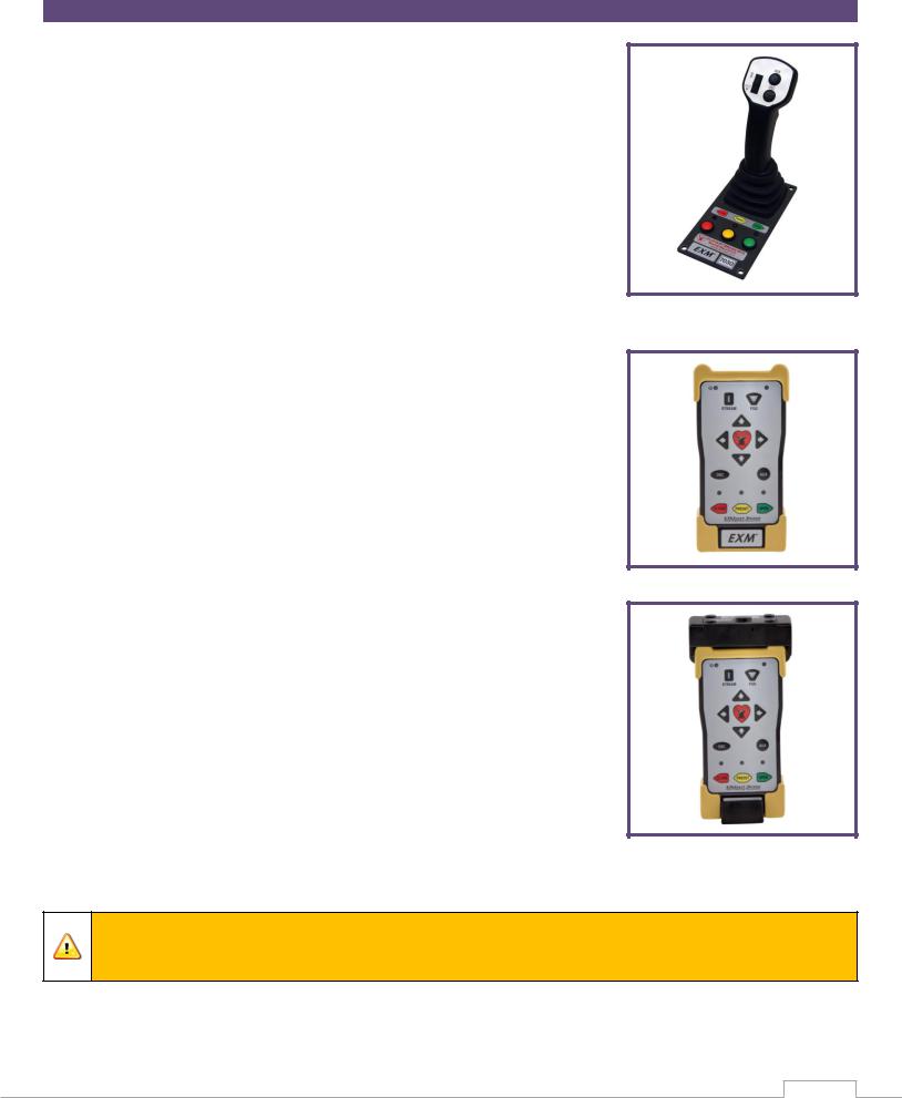
CONTROL
Joystick Controller - 7030
The Joystick Controller must be used in conjunction with the 7070 OEM Interface Module (Joystick and OEM Interface Module can be ordered together as the 7035 package). The Joystick Controller can be mounted inside the apparatus cab to control all monitor functions, including oscillation. The monitor direction (both vertical and horizontal movement) is changed by moving the joystick in the desired direction of travel. The up-down and left-right motions can be operated simultaneously with pressure sensitive speed, moving the monitor faster or slower depending on how far the joystick is pushed and pulled. The water valve can be opened with a trigger switch located on the front of the joystick or can be locked into position through the use of the valve buttons on the joystick. Nozzle pattern can be changed using the thumb wheel on the top of the joystick. Oscillation is programmed by using the joystick in conjunction with the oscillate button.
Panel Mount Controller – 7010
The Panel Mount Controller is a sealed controller for operation of the monitor, nozzle, and water valve (optional). Separate push button switches are provided for up, down, left, right, fog and straight stream, valve open, valve close, valve preset, oscillation, and auxiliary functions. The Panel Mount may be powered with 12 or 24 Volts.
Handheld Controller with Docking Station– 7015
When paired with battery pack, docking station, and RF transceiver module, the Panel Mount Controller becomes a Handheld Controller. The Handheld Controller is a sealed remote control that contains all the controls necessary for operation of the monitor, nozzle, and water valve (optional). The handheld wireless remote allows the operator to control the monitor from a significantly improved point of view, allowing the operator to confirm that they are hitting the desired target. Separate push buttons are provided for up, down, left, right, fog and straight stream, valve open, valve close, valve preset, oscillation, and auxiliary functions. The handheld remote, through the use of frequency hopping techniques, allows multiple transmitters to operate on a common site without interference. The remote also has an automatic power down feature that will shut down the power after 5 minutes of no activity. As an additional power saving feature, the radio signal is only transmitted while buttons are pushed. The handheld remote case has a NEMA 4 rating. The Handheld may be powered with 12 or 24 Volts.
Caution: Any modification of the Joystick, Panel Mount, or Handheld Controller enclosures will destroy the NEMA 4 rating to that piece of equipment and will void the warranty coverage.
6

OEM Interface Module - 7070
The OEM Interface Module is used in conjunction with either the Elkhart Brass or customer supplied joystick, or OEM installed switches. The OEM Interface Module may be configured to handle switching power or ground. The Interface Module provides the option of mounting a joystick or switches in the apparatus cab to control all monitor functions, including oscillation. The OEM Interface Module may be powered with 12 or 24 Volts.
MONITOR ACCESSORY
Position Feedback Display - 7051
All EXM monitors come with Absolute Position Feedback sensors. These sensors provide constant feedback to the monitors’ processor even when the monitor is moved via manual override. This information is then transmitted to the Position Feedback Display.
EXM CAN Stow Module7095
The EXM CAN Stow Module provides electrical outputs to which an OEM can connect to in order to enable/disable truck operations based on whether an EXM monitor is stowed or not stowed. This could be used, for example, for a truck that has an aerial or other movable object that may hit the monitor if moved when the monitor is not stowed. These outputs could also be used to turn OEM-supplied indicator lights on or off depending on the monitor stow state.
External RF Antenna Module - 7062
The External RF Antenna Module can be utilized with an RF equipped 7070 OEM Interface Module. The 10ft. extension harness allows the antenna to be mounted in a position with a better line of sight to the monitor. Use of the external RF antenna module is required for aerial applications. The external antenna should also be used with the OEM interface module when RF interference is likely.
RF Transceiver Module - 7061
The RF Transceiver Module can be used with any input controller to enable RF communication within the EXM system.
Light Kit – 7083/7084
The Light Kit provides illumination specifically for the areas targeted by EXM monitors. The Light Kit is mounted on top of the discharge elbow and follows the aim of the monitor. Installation instructions are included with the light kit.
7083 – Light Kit with light control module and light bar included 7084 – Light Kit with light control module only
7

CAN Connector Kit - 37221000
This kit provides the wired connectors needed to branch off the main CAN communication line, and allows you to connect another EXM component between the two EXM components at the ends of the main line. One kit is needed for each additional EXM component that is added to the main CAN line.
VALVE
Unibody Valve with E3F Electric Actuator -
The  water valve kit provides a convenient remote on/off and preset valve positioning control of the water supply to the
 . This allows the operator complete control of the unit from the safety of the vehicle cab or handheld radio controller. The water valve motor speed prevents water hammer, yet closes quickly enough to help preserve the limited on-board water supply. The electric actuated Unibody Valve may be powered with 12 or 24 Volts.
8

INSTALLATION INSTRUCTIONS
Installation Overview:
Step 1 – Mount and Wire All System Components
Step 2 – Configure the EXM System (If Required)
Step 3 – Calibrate the EXM System
Step 4 – Check Installation
Recommended electrical requirements for |
monitor: |
|
Power and Ground wire gauge and length: |
Distance Ft.(m) |
Wire Gauge (AWG) |
|
100(30.5) – 150(45.7) |
8 |
|
50(15.2) < 100(30.5) |
10 |
|
25(7.62) < 50(15.2) |
14 |
|
< 25(7.62) |
16 |
Power and Ground wire type: Cross Link or equivalent (Must meet or exceed NFPA 1901 Section 13)
Maximum monitor amperage draw: 20 AMPS
CAN wire gauge and length:
o Main Line: 131 ft. (40 m) – 18-20 AWG (Must meet J1939 specification)
o Branch (node) Line: 3 ft. (1 m) – 18-20 AWG (Must meet J1939 specification)
CAN wire type and shielding: Twisted shielded pair - 105°C 150V (Belden 9841 series or equivalent) o Shield Drain: Connect shield/drain to pin C of J1939 connector
Recommended electrical requirements for the 7000 series input devices:
Power and Ground wire gauge and length: 18-20 AWG 105°C 150V up to 150 ft. (45.7 m)
Maximum input controller amperage draw: 500mA
CAN wire gauge and length: 3 ft. (1 m) – 18-20 AWG
CAN wire type and shielding: Twisted shielded pair - 105°C 150V (Belden 9841 series or equivalent) o Shield Drain: Connect shield/drain to pin C of J1939 connector
Docking station wire gauge type: 20 AWG cross link or equivalent
Termination Points:
When using CAN lines for communication there must be 2 termination points within the system. Termination points are explained further in the Configuration section (installation step 2). What is important at this time is that in order to maximize the efficiency of communication in your CAN network, you must terminate the two components at the extreme ends of your main CAN line. This should be taken into consideration as you setup your EXM system. Each additional EXM component that requires connection to the main CAN communication line between the two end components will require the use of CAN Connector Kit (P/N 37221000). The maximum length of wire from the main CAN line is 3ft. and would be considered a branch (node) off the main CAN line.
CAN Connector Kit:
You may install any of the EXM CAN components that require the use of a CAN Connector Kit (P/N 37221000) by plugging the tri-pin CAN connector from the EXM component directly into the wye connector (Deutsch DT04-3P-P007) of the CAN Connector Kit. You can also use the crimp connectors on the mating connector leads to make your own connection.
9

Installation Step 1: Mount and Wire All System Components
Monitor – |
|
Before mounting the |
monitor, ensure that space allows for monitor to be |
rotated and calibrated. Disconnect all electrical connections.
Mount the monitor onto base:
oFlanged Base – Mount the monitor onto an appropriate flatface flange with 5/8-11 UNC grade 5, carbon steel or stainless steel bolts & nuts (3” flange or DN80-PN16: 4 bolts, 4” flange: 8 bolts). Seal flange joint with gasket or suitable flange sealant, and torque bolts uniformly (20 ft-lbs at a time in a crisscross pattern) to 60-70 ft-lbs using blue Loctite 242 or equivalent.
oThreaded Base – Thread monitor onto appropriate threaded pipe using Loctite 592 or equivalent thread sealant. Tighten using a strap wrench on the hex portion of the monitor base.
If the monitor will use a CAN line to communicate with other EXM components, connect plug 1 leads to the appropriate CAN line leads.
oIf the monitor will use RF (radio frequency) to communicate with other EXM components, no preparations are required. The monitor is already RF enabled.
oIf the CAN leads will not be used, replace wires with appropriate plugs.
Supply power to the monitor by connecting the red and black leads from the 6 pin connector to an appropriate power source. Install a 20 Amp fuse into the positive power lead for a 12V system (10 Amp for 24V system) to protect the monitor electrical components.
Refer to the respective plug figures for information on the plugs’ pins.


 Caution: Do NOT use motors or discharge as leverage to tighten monitor.
Warning: When installing the monitor on a raised face companion flange, it is critical that the bolts be tightened uniformly to prevent misalignment of the monitor relative to the flange or valve. If the monitor becomes misaligned, the base flange will fracture and fail when the bolts on the “high” side are tightened.
1
2
2
1
10
Proximity Sensor for Extended Travel –
An OEM supplied proximity sensor is used only for extended travel functionality, and is not necessary for standard monitor operation.
The Cobra EXM is capable of vertical extended travel beyond the calibration point (straight up). An additional ground input is needed to enable this functionality. This functionality is intended to allow an OEM supplied proximity sensor to be used to enable or disable extended travel when the monitor is used with aerial applications. The proximity sensor should provide an open circuit under normal operation, and a ground when the monitor can move into the extended travel region.
Disconnect monitor power and locate the Power/CAN connector provided with monitor.
Remove the position 3 plug from the Power/CAN connector.
Remove the orange wedge lock from end of the connector.
Insert the contact end of the proximity sensor wire into position 3 until it snaps into place.
Reinstall the orange wedge lock into the end of the connector.
Reconnect connector and configure the EXM system for extended travel functionality before use.
Connecting an OEM supplied proximity sensor to the wire from position 3 will provide conditional extended travel functionality via a ground or open circuit (see Operating Instructions). Connecting the proximity sensor wire from position 3 to a ground will provide an always enabled extended travel.
Panel Mount Controller - |
|
|
|
Using the Panel Mount Controller template in the |
|
|
|
Component Mounting Templates section, drill any 4 of |
|
|
|
the 7/32” holes shown through the panel intended to |
|
|
|
hold the Panel Mount. |
|
|
|
Mount the controller with four (4) 10-24 x ½” screws |
|
|
|
using blue Loctite 242 or equivalent. Screw length |
|
|
|
should provide 0.187”-0.25” thread engagement into |
|
|
|
panel mount. Torque screws to 50-60 in-lbs. |
|
|
|
If the Panel Mount will use the CAN line to communicate |
|
1 |
2 |
with the other EXM components, connect plug 1 leads to |
|
||
1 |
2 |
|
|
the appropriate CAN line. |
|
|
|
|
|
|
11 |

If the Panel Mount will use RF communication, install the RF Transceiver Module into the controller.
o Remove the back cover from the Panel Mount Controller using a flathead screwdriver.
o Connect the RF Transceiver with the wires running the length of the board as shown in the picture to the right.
o Reattach the back cover of the Panel Mount. Ensure no wires are pinched.
o If the CAN leads will not be used, replace wires with |
|
|
RF Transceiver in Panel Mount |
||
appropriate plugs. |
||
|
Supply power to the controller by connecting plug 2 leads to an appropriate power source.
Install a 1 Amp fuse into the positive power lead for a 12V system (1/2 Amp for 24V system).
Refer to the respective plug figures for information on the plugs’ pins.
1 |
2 |
Handheld Controller and Docking Station –
Using the Docking Station template shown in the Component Mounting Templates section, drill all 7/32” holes shown through the panel intended for mounting the Docking Station.
Mount the Docking Station with the supplied 10-24 x
3/8” screws using blue Loctite 242 or equivalent.
Torque screws to 50-60 in-lbs. The screw length allows for a panel thickness range of 0.046”-0.125”.
Supply power to the Docking Station by connecting the plug leads shown to an appropriate unswitched power source.
Install a 1 Amp fuse into the positive power lead of the Docking Station for a 12V system (1/2 Amp for 24V system).
Lift the Docking Station top and place the Handheld Controller into the station. Then push the top down until the contacts connect with the handheld. (see maintenance instructions section B for LED signals)
For instructions on converting a Panel Mount Controller to a Handheld Controller, refer to the steps below.
12

Converting the Panel Mount Controller into a Handheld Controller –
(Using Handheld Conversion Kit)
Handheld Conversion Kit will include Battery Pack, Docking Station, and all hardware.
Install a RF Transceiver Module into the back of the Panel Mount Controller as instructed in the Panel Mount installation section.
Connect Battery Pack plugs to the Panel Mount Controller as shown.
The CAN connector will not be used and should be placed inside the Battery Pack as shown.
Attach Battery Pack to the Panel Mount Controller using the provided 10-24 x ¾” screws. Torque screws to 50-60 in-lbs. Ensure no wires are pinched or exposed.
Joystick Controller and OEM Interface Module – |
|
|
|
Using the Joystick Controller template shown in the |
Valve Plug |
Component Mounting Templates section, drill all holes shown |
|
through the panel intended for mounting the Joystick |
|
Controller. |
|
Mount the Joystick Controller using 10-24 x ½” fasteners
secured with blue Loctite 242 or equivalent. |
2 |
Using the OEM Interface template shown in the Component
Mounting Templates section, drill all 4 of the 7/32” holes |
|
shown. |
1 |
Mount the OEM Interface Module with four (4) 10-24 x ½” fasteners secured with blue Loctite 242 or equivalent.
Connect the plug coming from the valve buttons on the Joystick Controller to the valve plug on the OEM Interface Module. (See picture to the right)
Connect the plug coming from the Joystick Controller stick to plug 2 on the OEM Interface Module. (See picture to the right)
If the Joystick/OEM will use CAN communication, connect the green, black, and blue leads coming from plug 1 to the appropriate CAN line. If the CAN leads will not be used, replace wires with plugs.
13
 Loading...