


8598
98298000 Rev. B

Table of Contents
I. Product Safety...................................................................................................................................... 1
II. System Features.................................................................................................................................. 2
III. System Component Descriptions ...................................................................................................... 4
A. 8598 Extender ............................................................................................................................. 4
B. Controller .................................................................................................................................... 4
IV. Control System Specifications ......................................................................................................... 4
V. Mounting Structure Requirements .................................................................................................... 5
VI. Installation Instructions .................................................................................................................. 10
A. Extender ....................................................................................................................................... 10
B. Controller ..................................................................................................................................... 12
C. Wiring .......................................................................................................................................... 13
VII. Operating Instructions ................................................................................................................... 14
VIII. Maintenance and Inspection ......................................................................................................... 15
A. Extender .................................................................................................................................... 15
B. Controller Understanding the controller LED’s ........................................................................... 15
IX. Parts Drawings ................................................................................................................................ 16
X. Hydraulic Data ................................................................................................................................. 18
I. Product Safety
Important:
Before installing and operating this equipment, read and study this manual
thoroughly. Proper installation is essential to safe operation. In addition, the
following points should be adhered to in order to ensure the safety of equipment and
personnel:
1 All personnel who may be expected to use this equipment must be thoroughly
trained in its safe and proper use.
2 Never exceed a moment of 9,480 in lbs at the outlet connection (see section V.
Mounting Structure Requirements).
3 Become thoroughly familiar with the hydraulic characteristics of this equipment
and the pumping system used to supply it. To produce effective fire streams,
operating personnel must be properly trained.
4 Whenever possible, this equipment should be operated from a remote location.
Do not needlessly expose personnel to dangerous fire conditions.
5 Open water valve supplying this equipment slowly, so that the piping fills slowly,
thus preventing possible water hammer occurrence.
6 After each use, and on a scheduled basis, inspect equipment per instructions
(see section VIII. Maintenance and Inspection)
7 Any modification to the controller’s enclosure will destroy the NEMA 4 rating and
void warranty coverage of the enclosure and all components within.
1
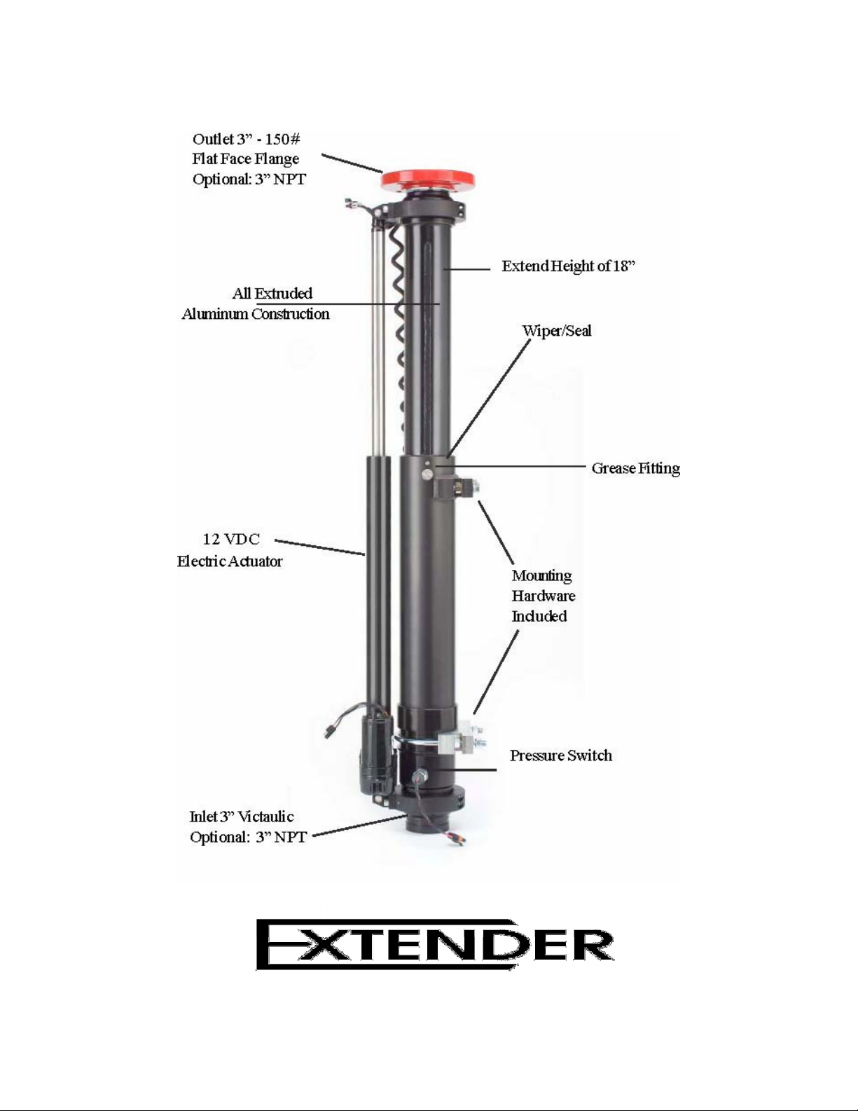
II. System Features
Figure 1
8598 Features
2

Figure 2
Extender Front Panel Controller Features
3

III. System Component Descriptions
A. 8598 Extender
The Extender is an electric operated telescoping waterway. It is designed to elevate a
deck monitor 18 inches so the stream path can clear obstructions like truck cab, lights,
hose bed, etc. It is designed to be used in full up position, but can be used in the full
down position. The water supply connection is 3 inch Victaulic (optional 3 inch NPT
male thread). The discharge connection is 3 inch 150 lb. ANSI pattern flange (optional 3
inch NPT male threads).
The maximum flow capacity is 1250 gallons per minute. The maximum inlet pressure is
200 psi. A pressure switch prevents the Extender from moving when internal pressure
exceeds 10 psi to prevent damage to equipment or injury to personnel caused by
unexpected changes in stream elevation.
B. Controller
The Extender’s control circuit uses a state-of-the-art control logic to keep the controller
size to a minimum. The controller utilizes modern switch styles to control the deck gun
elevator. A momentary push elevates or lowers the unit. The unit does not stop in mid
position. An optional in-cab warning lamp (supplied by the OEM) shows if the Extender
is not fully retracted.
IV. Control System Specifications
Truck Voltage
Minimum 11 VDC to Maximum 15 VDC
Recommended Ratings
Operating voltage - 13.8 VDC
Primary fuse rating - 10A
Position warning output fuse rating - 125mA
Extender
Maximum flow capacity is 1250 gpm
Maximum inlet pressure rating is 200 psi
Maximum moment is 9,480 in/lbs at the outlet connection
Moment = RFxH
Where RF = Reaction Force (Pounds)
H=Height of vertical discharge pivot (Inches) (See Figure 3)
4
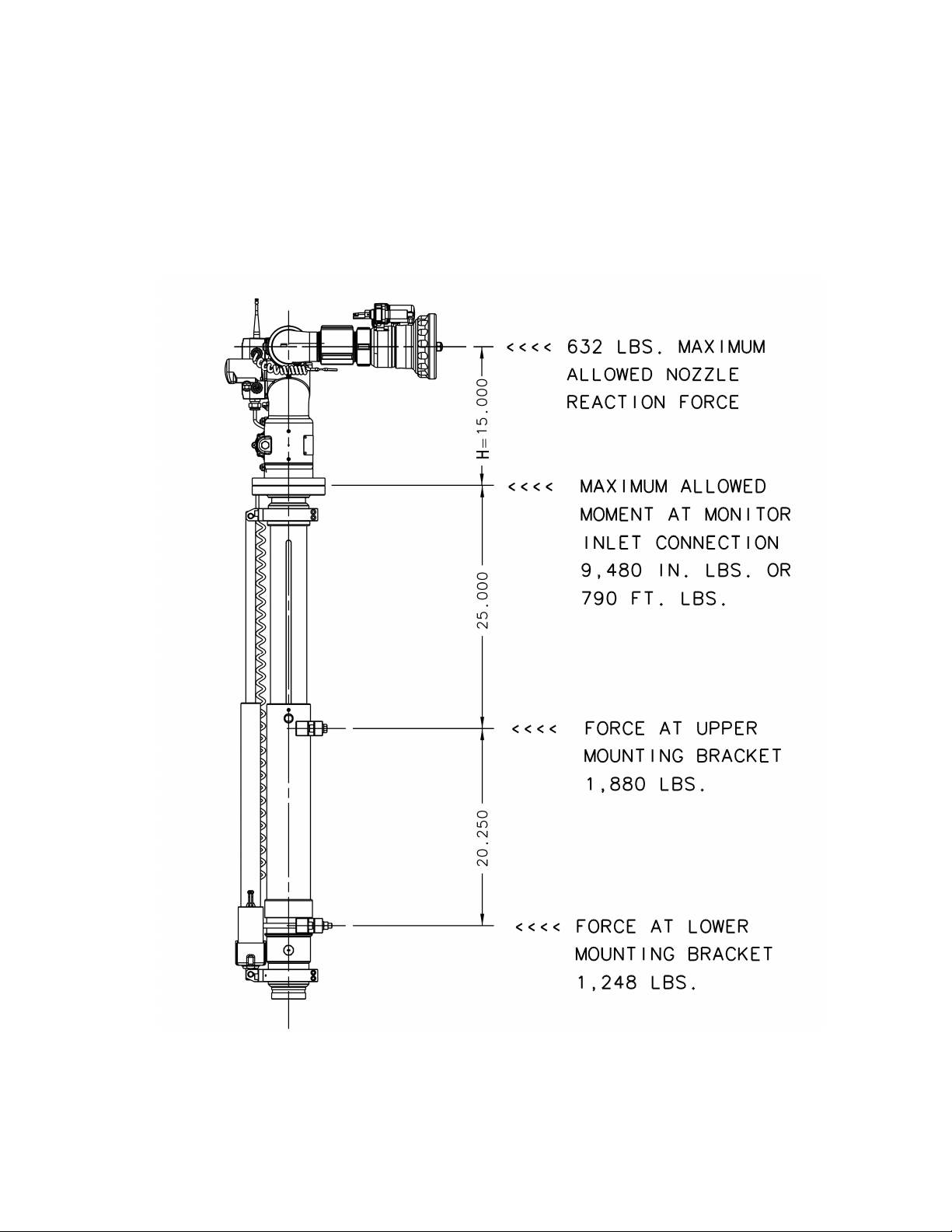
V. Mounting Structure Requirements
The mounting structure must be able to safely withstand the forces shown in Figure 3.
For monitor and nozzle combinations other than Elkhart 8500 RF and SM-1250E
consult Elkhart Brass engineering department or calculate moment at monitor inlet.
Moment must not exceed 9480 in/lb or 790 ft/lb. (See nozzle reaction formulas on page
6.)
Figure 3
Forces
5
 Loading...