


Installation, Operating,
&
Maintenance Instructions
Model 8297 2.0
Break-Apart Portable Monitor & Accessories
98272000 REV-E
1302 West Beardsley Ave • Elkhart, IN 46514 • 1-574-295-8330 • 1-800-346-0250
© 2014 Elkhart Brass Mfg. Co., Inc. • WWW.ELKHARTBRASS.COM

|
Table of Contents |
|
|
I. PRODUCT SAFETY ................................................................................................................................... |
|
|
3 |
II. PRODUCT DESCRIPTION ......................................................................................................................... |
|
|
5 |
A. 8297 |
Upper Monitor Assembly .............................................................................. |
|
5 |
B. 8298 2.0 Deck Mount Adapters...................................................................................................... |
|
5 |
|
C. 81315001 3” Companion Flange Kit .............................................................................................. |
|
6 |
|
D. Portable Bases ................................................................................................................................ |
|
|
6 |
E. 8297MB Storage Bracket................................................................................................................ |
|
6 |
|
F. 8299 2.0 Deck Mount Adapter........................................................................................................ |
|
7 |
|
G. 8298EX 2.0 |
.......................................................................................................... |
|
7 |
H. 8298EX-MB |
Mounting Bracket ........................................................................... |
|
7 |
I. 81460001 Anchor Kit....................................................................................................................... |
|
7 |
|
III. INSTALLATION ...................................................................................................................................... |
|
|
8 |
A. 8298F 2.0 Deck Mount Adapter..................................................................................................... |
|
8 |
|
B. 8298P 2.0 Deck Mount Adapter ..................................................................................................... |
|
8 |
|
C. 8299 2.0 Deck Mount Adapter ....................................................................................................... |
|
9 |
|
IV. OPERATION ........................................................................................................................................ |
|
|
11 |
A. Deck Gun Mode ........................................................................................................................... |
|
|
11 |
1. Attachment and Operation ...................................................................................................... |
|
11 |
|
2. Monitor Removal .................................................................................................................... |
|
12 |
|
B. Portable Monitor Mode................................................................................................................. |
|
12 |
|
D. 8298EX 2.0 |
........................................................................................................ |
|
13 |
V. MAINTENANCE .................................................................................................................................... |
|
|
14 |
A. Preventive Maintenance Procedures for |
Upper Assembly ................................... |
14 |
|
1. After Each Use: ....................................................................................................................... |
|
|
14 |
2. As Needed: .............................................................................................................................. |
|
|
14 |
B. Maintenance Procedures for Stinger 2.0® Bases .......................................................................... |
|
15 |
|
1. After Each Use: ....................................................................................................................... |
|
|
15 |
2. As Needed: .............................................................................................................................. |
|
|
15 |
VI. MONITOR & STREAM SHAPER HYDRAULIC DATA .............................................................................. |
|
17 |
|
2

I. PRODUCT SAFETY
 Important:
Before installing and operating this equipment, read & study this manual thoroughly. Proper installation is essential to safe operation. In addition, the following points should be adhered to in order to ensure the safety of equipment and personnel:
All personnel who may be expected to use this equipment must be thoroughly trained in its safe and proper use.
Before flowing water from this device, check that all personnel (fire service and civilian) are out of the stream path. Also, check to make sure stream direction will not cause avoidable property damage.
Become thoroughly familiar with the hydraulic characteristics of this equipment, and the pumping system used to supply it. To produce effective fire streams operating personnel must be properly trained.
Open water valve supplying this equipment slowly, so that piping and hose lines fill slowly, thus preventing possible water hammer occurrence.
After each use, and on a scheduled basis, inspect equipment per instructions in section V.
Always determine that latch pins are fully engaged (see Fig. 13 pg.11).
Never exceed 1250 GPM flow in any mode.
Never lower the discharge below the safety stop in portable mode.
Always engage left/right lock when un-manned or not in use.
Always secure the monitor with the safety strap in portable mode.
Never attempt to move the monitor’s portable base while flowing water.
Always inspect the ground spikes for damage after each use.
Master streams are extremely powerful. Therefore, great care must be taken in directing such streams to avoid injury to personnel and unwanted damage to property.
3
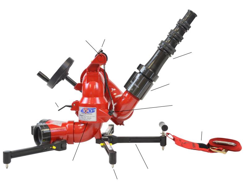
Twist Release Handle |
Twist-Lock Pin |
Horizontal Rotation Lock
Patented Break-apart
Swivel Joint
Carbide Tipped
Ground Spikes
Quad Stacked
Smooth Bore Tips
Stream Shaper
Latch Pin Visual Indicator
Safety Strap
Forged Aluminum Legs
Fig. 1
 W/ 282-A Stream
Shaper & Quad Stacked Tips
4

II. PRODUCT DESCRIPTION
A. 8297  Upper Monitor Assembly
The 8297 Stinger 2.0® Portable Monitor is a lightweight dual-purpose monitor. The highly efficient cast aluminum waterway contains a central vane to minimize large-scale turbulence and provide superior fire streams. The patented break-apart swivel joint allows one upper assembly to be used with either of two truck mount adapters or one of the many portable bases. The vertical stream direction is controlled by a handwheel driving a worm gear. The horizontal stream direction is controlled by disengaging the left-right lock and moving the return bend by hand. The maximum monitor flow capacity is 1250 gallons per minute with most base adapters (the clappered Siamese inlet is rated at 1000 GPM).
Stinger 2.0® monitors are normally supplied with the 282A and ST-194 Stacked Tip combination. The SM-1250  constant pressure (automatic) type master stream nozzle is also available for use with the Stinger 2.0®.
The following additional features are also provided in the Stinger 2.0® monitor:
Twist Release Handle and Lock Pin
The twist release handle makes a convenient carrying handle for both the Stinger 2.0® upper and the Stinger 2.0® with a portable base attached. It also provides for a quick conversion from the deck mode to portable base mode. The lock pin ensures that the user does not accidentally activate the twist release handle while carrying the Stinger 2.0® attached to the portable base.
Elevation Safety Stop Pin
The stop pin alerts the operator when the elevation has reached its lowest point before needing manual over-ride. The manual over-ride should only be used when the Stinger 2.0® monitor is attached to the 8298 2.0 or 8299 2.0 deck mount adapters. Using the over-ride while in portable mode can cause serious injury or death to nearby personnel.
Latch Pin Visual Indicator
The visual indicator is used to quickly determine when latch pins are engaged. When the latch pins are properly engaged, no part of the pins should be visible in the indicator cutout of the latch pin cap.
Left-Right Lock Lever
The left-right lock is designed to engage only when the upper monitor assembly is installed on a truck mount or portable base. The left-right lock lever visually indicates the status of the lock.
B. 8298 2.0 Deck Mount Adapters
The 8298 2.0 deck mount adapter allows use of the 8297 2.0 as a deck gun, and is designed for a pre-plumbed pipe directly from the pump. The 8298F 2.0 adapter consists of the 3” 150# flat faced ANSI flange, cast waterway, swivel ring, and antirotation pins for the 8298EX 2.0. The 8298P 2.0 adapter consists of the 3” NPT female thread, cast waterway, swivel ring, and anti-rotation pins for the 8298EX 2.0.
Fig. 2
8298F 2.0 Deck Mount Adapter
5

C. 81315001 3” Companion Flange Kit
Elkhart Brass offers a 3” companion flange kit to be used with the 8298F 2.0 deck mount adapter. The kit consists of an ANSI 3” 150# flange, four 5/8 – 16 bolts with nuts, and a 3” gasket.
Fig. 3
3" Companion Flange Kit
D. Portable Bases
There are six optional portable bases available:
1.Two 2.5” clappered female swivel inlets
2.One 3.5” swivel inlet
3.One 4.0” swivel inlet
4.One 4.5” swivel inlet
5.One 4.0” Storz inlet
6.One 5.0” Storz inlet
The portable base support legs can be folded for compact storage in an apparatus compartment or hose bed pre-connected to a supply hose line. The folding legs are designed to be easily rotated from the stored position to the extended and locked position and back again. The spring loaded carbide ground spikes are very hard and very sharp, important factors in the prevention of sliding under flow.
Fig. 4
5" Storz Base
Fig. 5
Dual 2.5" Siamese Base
E. 8297MB Storage Bracket
The 8297MB is an optional, lightweight bracket that is designed to hold the Stinger 2.0® securely in place while in storage. The 8297MB can be used to store the complete monitor or the portable base separate from the upper monitor. A single release lever allows for fast and efficient removal of the unit from the storage bracket. The bracket can be mounted either horizontally or vertically. (Not intended to be used while flowing water.)
Fig. 6
8297MB Storage Bracket
6
 Loading...