


ELKHART BRASS MFG. CO., INC.
1302 WEST BEARDSLEY AVENUE •P.O. BOX 1127 •ELKHART IN 46515 •(574) 295-8330 •FAX (574) 293-9914
Installation, Operating,
& Maintenance Instructions
8494 
Monitor
98275000 REV. C

TABLE OF CONTENTS
I. |
PRODUCT SAFETY..................................................................................................... |
1 |
|
II. |
SYSTEM COMPONENT DESCRIPTIONS ....................................................................... |
3 |
|
A. |
|
Monitor ........................................................................................................ |
3 |
B. |
|
81206000 Control Module....................................................................................................... |
3 |
C. |
81122001 Standard Control Box ............................................................................................. |
4 |
|
D. |
81172001 Joystick Control Box (Optional)............................................................................. |
4 |
|
E. |
|
5000 Series Nozzles................................................................................................................. |
4 |
F. |
81181001 Water Valve Kit (Optional) .................................................................................... |
5 |
|
G. |
|
SM-10FE De/Anti-Icing Nozzle.............................................................................................. |
5 |
III. |
CONTROL SYSTEM SPECIFICATIONS ......................................................................... |
6 |
|
A. |
|
Monitor Controller Specifications ........................................................................................... |
6 |
B. |
Optional Valve Controller Specifications................................................................................ |
6 |
|
IV. |
INSTALLATION INSTRUCTIONS .................................................................................. |
7 |
|
A. |
|
Component Mounting .............................................................................................................. |
7 |
|
1. |
Monitor......................................................................................................... |
7 |
|
2. |
81206000 Control Module................................................................................................... |
8 |
|
3. |
81122001 Control Box & 81172001 Joystick Control Box (Optional)............................... |
8 |
|
4. |
81181001 Water Valve Kit (Optional) .............................................................................. |
10 |
V. |
OPERATING INSTRUCTIONS ..................................................................................... |
12 |
|
A. |
|
Normal Operation .................................................................................................................. |
12 |
|
1. |
81122001 Standard Control Box ....................................................................................... |
12 |
|
2. |
81172001 Joystick Control Box ........................................................................................ |
12 |
B. |
|
Manual Override .................................................................................................................... |
12 |
VI. |
MAINTENANCE ....................................................................................................... |
13 |
|
A. |
|
Preventive Maintenance......................................................................................................... |
13 |
VII. |
MONITOR & NOZZLE HYDRAULIC DATA................................................................ |
14 |
|
VIII. |
|
PARTS DRAWINGS ............................................................................................... |
17 |

I.PRODUCT SAFETY
 Important:
Before installing and operating this equipment, read & study this manual thoroughly. Proper installation is essential to safe operation. In addition, the following points should be adhered to in order to ensure the safety of equipment and personnel:
1.All personnel who may be expected to use this equipment must be thoroughly trained in its safe and proper use.
2.Before flowing water from this device, check that all personnel (fire service and civilian) are out of the stream path. Also, check to make sure stream direction will not cause avoidable property damage.
3.Become thoroughly familiar with the hydraulic characteristics of this equipment, and the pumping system used to supply it. To produce effective fire streams, operating personnel must be properly trained.
4.Whenever possible, this equipment should be operated from a remote location. Do not needlessly expose personnel to dangerous fire conditions.
5.Open water valve supplying this equipment slowly, so that the piping fills slowly, thus preventing possible water hammer occurrence.
6.After each use, and on a scheduled basis, inspect equipment per instructions in section VI.
7.Any modifications to the electrical enclosures will destroy the NEMA 4 rating and void warranty coverage of the enclosure and all components within.
1

Figure 1
8494  Monitor
2
II. SYSTEM COMPONENT DESCRIPTIONS
A.  Monitor
The  Monitor is specially designed to mount on the front bumper of off-road or wildland fire fighting apparatus. It rotates either 180° or 334° to spray straight ahead or to either side for use in fighting forest, grass, range, brush and similar fires. In addition, because
  is controlled from inside the cab, risk to firefighters is significantly reduced.
The  features durable Elk-O-Lite® construction combined with rugged, stainless steel gears and motors that are completely enclosed and sealed for maximum protection from the elements. The
  has a flow efficient 2.0” vaned waterway to minimize turbulence and provide superior fire streams. Water supply is provided through the monitor base by 2” National Pipe Thread connection. The discharge nozzle connection is a 1½” National Hose Thread. Nozzle stream direction is controlled by two permanent magnet type gear motors, one controlling rotation about the axis of the water inlet, and the other controlling nozzle elevation and depression.
An optional 2.0” electric valve kit is available to allow the user to control water flow directly from the  control box. This enables “pump and roll” functionality with complete control by the operator in the cab of the truck.
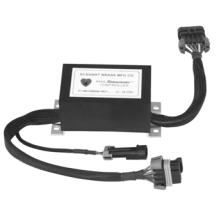
B. 81713000 Control Module
The control module is completely encapsulated in
epoxy for maximum protection from the elements. The module has reverse polarity protection to
prevent damage to the electronic components. The module uses feedback from Hall effect sensors to determine when the monitor travel limits have been reached. It also uses dynamic braking to stop the motors for precision motion control.
Figure 2
81713000 Control Module
3
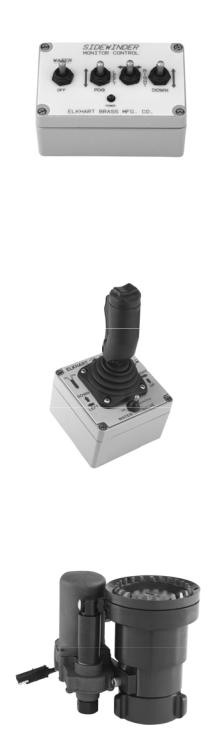
C. 81122001 Standard Control Box
The standard control box consists of a weathertight enclosure with toggle switches that is suitable for mounting inside or outside the apparatus. The toggle switches control the water supply (On-Off), monitor direction (Left-Right and Up-Down), and nozzle pattern (Straight Stream-Fog).
Figure 3
81122001 Standard Control Box
D. 81172001 Joystick Control Box (Optional)
The joystick control box is suitable for mounting inside the apparatus cab. The joystick controls all four functions. The water supply is controlled with a trigger switch on the front of the joystick. The water can also be run continuously by activating the toggle switch mounted on the enclosure. Nozzle pattern is changed using the rocker switch on the top of the joystick. The monitor direction is changed by moving the joystick in the desired direction.
Figure 4
81172001 Joystick Control Box
E. 5000 Series Nozzles
Three constant flow electric nozzles are offered with the  monitor, with flows ranging from 15 to 350 GPM. The nozzle pattern is electrically actuated and controlled by the monitor control box.
Available in 12 VDC or 24 VDC.
5000-04; 15, 30, or 45 GPM 5000-14; 60, 95, 125, or 150 GPM 5000-24; 175, 200, 250, or 350 GPM
4
Figure 5
5000-24 Electrically Actuated Nozzle

F. 81181001 Water Valve Kit (Optional)
The  water valve kit provides a convenient remote on-off control of the water supply to the 8494
  . This allows the operator complete control of the unit from the safety of the vehicle cab. It also allows a “pump and roll” capability. The water valve motor prevents water hammer, yet closes quickly enough to help preserve the limited on-board water supply. The 81181001 Water Valve Kit is for 12VDC use only. The 81298001 Water Valve Kit (24V) is available for use with 24VDC systems. It includes a 24-12 volt converter to power the water valve and control module.
G. SM-10FE De/Anti-Icing Nozzle
Designed for the aircraft deicing industry, this nozzle has been designed for use with type 1 deicing, type 2 anti-icing, or type 4 anti-icing fluids. The SM-10FE has Viton® O-rings to withstand the use of the Ethylene Glycol and Propylene Glycol solutions used to de-ice aircraft. The nozzle is constant gallonage at pressures below 90 Psi and becomes automatic at 95 Psi. It is designed to deliver 20 GPM at 50 Psi and 30 –120 GPM from 90-110 Psi.
Available in 12 VDC or 24 VDC.
5
Figure 6
2920E Electrically Actuated Valve
Figure 7
SM-10FE De/Anti-Icing Nozzle
 Loading...