


H87H3-M

Preface
Copyright
This publication, including all photographs, illustrations and software, is protected
under international copyright laws, with all rights reserved. Neither this manual, nor
any of the material contained herein, may be reproduced without written consent of
the author.
Version 1.0
Disclaimer
The information in this document is subject to change without notice. The manufacturer makes no representations or warranties with respect to the contents hereof
and specifically disclaims any implied warranties of merchantability or fitness for
any particular purpose. The manufacturer reserves the right to revise this publication and to make changes from time to time in the content hereof without obligation
of the manufacturer to notify any person of such revision or changes.
Trademark Recognition
Microsoft, MS-DOS and Windows are registered trademarks of Microsoft Corp.
MMX, Pentium, Pentium-II, Pentium-III, Celeron are registered trademarks of Intel
Corporation.
Other product names used in this manual are the properties of their respective owners
and are acknowledged.
Federal Communications Commission (FCC)
This equipment has been tested and found to comply with the limits for a Class B
digital device, pursuant to Part 15 of the FCC Rules. These limits are designed to
provide reasonable protection against harmful interference in a residential installation. This equipment generates, uses, and can radiate radio frequency energy and,
if not installed and used in accordance with the instructions, may cause harmful
interference to radio communications. However, there is no guarantee that interference will not occur in a particular installation. If this equipment does cause harmful
interference to radio or television reception, which can be determined by turning
the equipment off and on, the user is encouraged to try to correct the interference by
one or more of the following measures:
• Reorient or relocate the receiving antenna
• Increase the separation between the equipment and the receiver
• Connect the equipment onto an outlet on a circuit different from that to
which the receiver is connected
• Consult the dealer or an experienced radio/TV technician for help
Shielded interconnect cables and a shielded AC power cable must be employed with
this equipment to ensure compliance with the pertinent RF emission limits governing this device. Changes or modifications not expressly approved by the system’s
manufacturer could void the user’s authority to operate the equipment.
H87H3-M USER MANUAL

Declaration of Conformity
This device complies with part 15 of the FCC rules. Operation is subject to the following conditions:
• This device may not cause harmful interference, and
• This device must accept any interference received, including interference
that may cause undesired operation.
This device is in conformity with the following EC/EMC directives:
EN 55022
EN 61000-3-2
EN 61000-3-3
EN 55024
EN 60950
CE marking
Limits and methods of mesurement of radio disturbance characteristics of information technology equipment
Disturbances in supply systems caused
Disturbances in supply systems caused by household appliances and similar electrical equipment “ Voltage fluctuations”
Information technology equipment-Immunity characteristicsLimits and methods of measurement
Safety for information technology equipment including electrical business equipment
Canadian Department of Communications
This class B digital apparatus meets all requirements of the Canadian Interferencecausing Equipment Regulations.
Cet appareil numérique de la classe B respecte toutes les exigences du Réglement
sur le matériel brouilieur du Canada.
About the Manual
The manual consists of the following:
Chapter 1
Introducing the Motherboard
Chapter 2
Installing the Motherboard
Chapter 3
Using BIOS
Chapter 4
Using the Motherboard Software
Chapter 5
Intel®Matrix Storage Manager
RAID Configurations
Chapter 6
AMD CrossFireXTM Technology
Support
Chapter 7
Trouble Shooting
Describes features of the
motherboard.
Describes installation of
motherboard components.
Provides information on using the BIOS Setup Utility.
Describes the motherboard
software.
Describes Intel
Storage Manager RAID
Configurations.
Describes AMD Crossfire
Technology
Provides basic trouble
shooting tips.
®
Matrix
TM
H
H
H
H
H
H
H
page 1
page 7
page 29
page 69
page 73
page 79
page 81
ii
H87H3-M USER MANUAL

TABLE OF CONTENTS
Preface i
Chapter 1 1
Introducing the Motherboard 1
Introduction...................................................................................1
Pakage Contents............................................................................1
Specifications................................................................................2
Motherboard Components..........................................................4
I/O Ports..............................................................................................6
Chapter 2 7
Installing the Motherboard 7
Safety Precautions.............................................................................7
Installing the Motherboard in a Chassis......................................7
Checking Jumper Settings.................................................................8
Installing Hardware..................................................................9
Installing the Processor.............................................................9
Installing the CPU Cooler.........................................................11
Installing Memory Modules....................................................12
Installing Add-on Cards...........................................................14
Connecting Optional Devices..................................................16
Installing a SATA Hard Drive...................................................24
Connecting Case Components.......................................................25
Front Panel Header.................................................................27
Chapter 3 29
Using BIOS 29
About the Setup Utility................................................................29
The Standard Configuration....................................................29
Entering the Setup Utility........................................................29
Resetting the Default CMOS Values.....................................30
Using BIOS........................................................................................30
BIOS Navigation Keys..............................................................31
Main Menu.............................................................................32
Advanced Menu......................................................................33
Chipset Menu..........................................................................49
M.I.B III(MB Intelligent Bios III) Menu....................................56
Boot Menu...............................................................................65
Security Menu..........................................................................66
Exit Menu................................................................................67
H87H3-M USER MANUAL
iii

Chapter 4 69
Using the Motherboard Software 69
Auto-installing under Windows XP/7/8......................................69
Running Setup.........................................................................69
Manual Installation..........................................................................71
ECS Utility Software (Intelligent EZ Utility).....................................71
Chapter 5 73
Intel® Matrix Storage Manager RAID Configuration 73
Before creating a RAID set...................................................................73
Entering Intel® Matrix Storage Manager RAID BIOS utility.........74
Creating a RAID set..........................................................................75
Deleting a RAID set...............................................................................77
Resetting disks to Non-RAID..............................................................78
Exiting Setup.........................................................................................78
Chapter 6 79
AMD CrossFireXTM Technology Support 79
Requirements....................................................................................79
TM
Installing CrossFireX
TM
The Catalyst
Control Center Dialog Box...................................80
graphics cards......................................79
Chapter 7 81
Trouble Shooting 81
Start up problems during assembly..............................................81
Start up problems after prolong use............................................82
Maintenance and care tips..............................................................82
Basic Troubleshooting Flowchart...................................................83
iv
H87H3-M USER MANUAL
Chapter 1
Introducing the Motherboard
Introduction
Thank you for choosing the H87H3-M motherboard. This motherboard is a high performance, enhanced function motherboard designed to support the LGA1150 socket
® 4th
for Intel
This motherboard is based on Intel
solution. It supports up to 32 GB of system memory with dual channel DDR3 1600/
1333 MHz. One PCI Express x16 Gen3 slot (Gray slot) and one PCI Express x16 Gen2
slot (Black slot runs at x4 mode) are supported, intended for Graphics Interface. In
addition, one PCI Express x1 Gen2 slot and one PCI v2.2 slot are for extending usage.
It integrates USB 2.0 and USB 3.0 interface, supporting up to ten USB 2.0 ports (four
USB 2.0 ports at rear panel and three USB 2.0 headers support additional six USB 2.0
ports) and four USB 3.0 ports (two USB 3.0 ports at the rear panel and one USB 3.0
header supports additional two USB 3.0 ports). The gray USB 2.0 header provides EZ
charger technology, please refer to
more details.
The motherboard is equipped with advanced full set of I/O ports in the rear panel,
including one PS/2 mouse and keyboard Combo connector, one VGA port, one DVI
port, one HDMI port, one RJ45 LAN connector, four USB 2.0 ports, two USB 3.0 ports
and audio 8-ch jacks.
In addition, this motherboard supports six SATA 6Gb/s connectors for expansion.
Generation CoreTM Family processors.
®
H87 Express Chipset for best desktop platform
Front Panel USB 2.0 headers of chapter 2 for
Package Contents
Your motherboard package ships with the following items:
H87H3-M Motherboard
Quick Installation Guide
User Manual
DVD
I/O Shield
2 SATA 6G Cables
Chapter 1
The package contents above are for reference only, please take the actual package items as
standard.
H87H3-M USER MANUAL
1
Chapter 1
Specifications
CPU
Memory
Expansion
Slots
AMD
CrossFireX
TM
Technology
Storage
Audio
LAN
Rear Panel I/O
Internal I/O
Connectors &
Headers
• LGA1150 socket for Intel
® 4th
Generation CoreTM Family
processors
• Supports CPU up to 84W, TDP up to 95W
• Supports Intel
• Supports Intel
• Supports Intel
• Supports Intel
• Supports Intel
- Intel
- Intel
®
Turbo Boost Technology
®
Hyper-Threading Technology
®
64 Architecture
®
Advanced Vector Extensions 2.0
®
®
®
Responsiveness Technologies
Rapid Storage Technology 12
Smart Response Technology*
- Intel® Rapid Start Technology*
Note: Please go to ECS website for the latest CPU support list.
*SSDS, multiple HDDs required.
• Intel® H87 ChipsetChipset
• Dual-channel DDR3 memory architecture
• 4 x 240-pin DDR3 DIMM sockets support up to 32 GB
• Supports DDR3 1600/1333 MHz SDRAM
Note: Please go to ECS website for the latest Memory support list.
• 2 x PCI Express x16 slots (one PCI Express Gen3 x16 slot & one
PCI Express Gen2 x4 mode slot)
• 1 x PCI Express x1 Gen2 slot
• 1 x PCI v2.2 slot
• Supports AMD CrossFireX
-
The PCIEX16_S1 (black color of PCIE x16 slot) supports PCI
TM
Technology
Express Gen2 running at X4 mode
• Supported by Intel® H87 Express Chipset
- 6 x Serial ATA 6Gb/s devices
- RAID 0, RAID 1, RAID 5, RAID 10 configuration
• Realtek ALC892 8-Ch High Definition audio CODEC
-
Compliant with HD audio specification
• Realtek RL8111G Gigabit Lan
• 1 x PS/2 mouse & keyboard Combo connector
• 1 x D-sub (VGA port)
• 1 x DVI port
• 1 x HDMI port
• 4 x USB 2.0 ports
• 1 x RJ45 LAN connector
• 2 x USB 3.0 ports
• 1 x Audio 8-ch jacks
• 1 x 24-pin ATX Power Supply connector
• 1 x 4-pin ATX 12V Power connector
• 1 x 4-pin CPU_FAN connector
• 1 x 3-pin SYS_FAN connector
• 1 x USB 3.0 header supports additional two USB 3.0 ports
2
H87H3-M USER MANUAL
System BIOS
AP Support
• 3 x USB 2.0 headers support additional six USB 2.0 ports (Gray
header supports EZ charger)
• 6 x SATA 6Gb/s connectors
• 1 x SPDIF out header
• 1 x Front Panel audio header
• 1 x Front Panel switch/LED header
• 1 x CIR header
• 1 x COM header
• 1 x CLR_CMOS jumper
• 1 x Parallel port header (LPT)
• 1 x Trusted platform module header (TPM)
• 1 x Speaker header
• 1 x Case open header
• 1 x ME_UNLOCK header
• AMI BIOS with 64Mb SPI Flash ROM
• Supports Plug and Play, STR (S3)/ STD(S4), Hardware Monitor
• Audio, LAN, can be disabled in BIOS
• F7 hot key for boot up devices option
• Supports ACPI & DMI
• Supports PgUp clear CMOS Hotkey (Has PS2 KB Model only)
• Supports 3 Independent Dispaly
• Supports Multi-Language
• Supports AC’97/HD Audio auto detect (default)
• Supports eBLU*1/eDLU/eSF*1/Cyberlink*2/Norton*2/Muzee*2/EZ
Charger
*1Microsoft .NET Framework 3.5 is required.
Note:
*2Free bundle software including ECS DVD: Cyberlink/Norton/
Muzee.
• ATX Size, 244mm x 220mmForm Factor
Chapter 1
H87H3-M USER MANUAL
3
Chapter 1
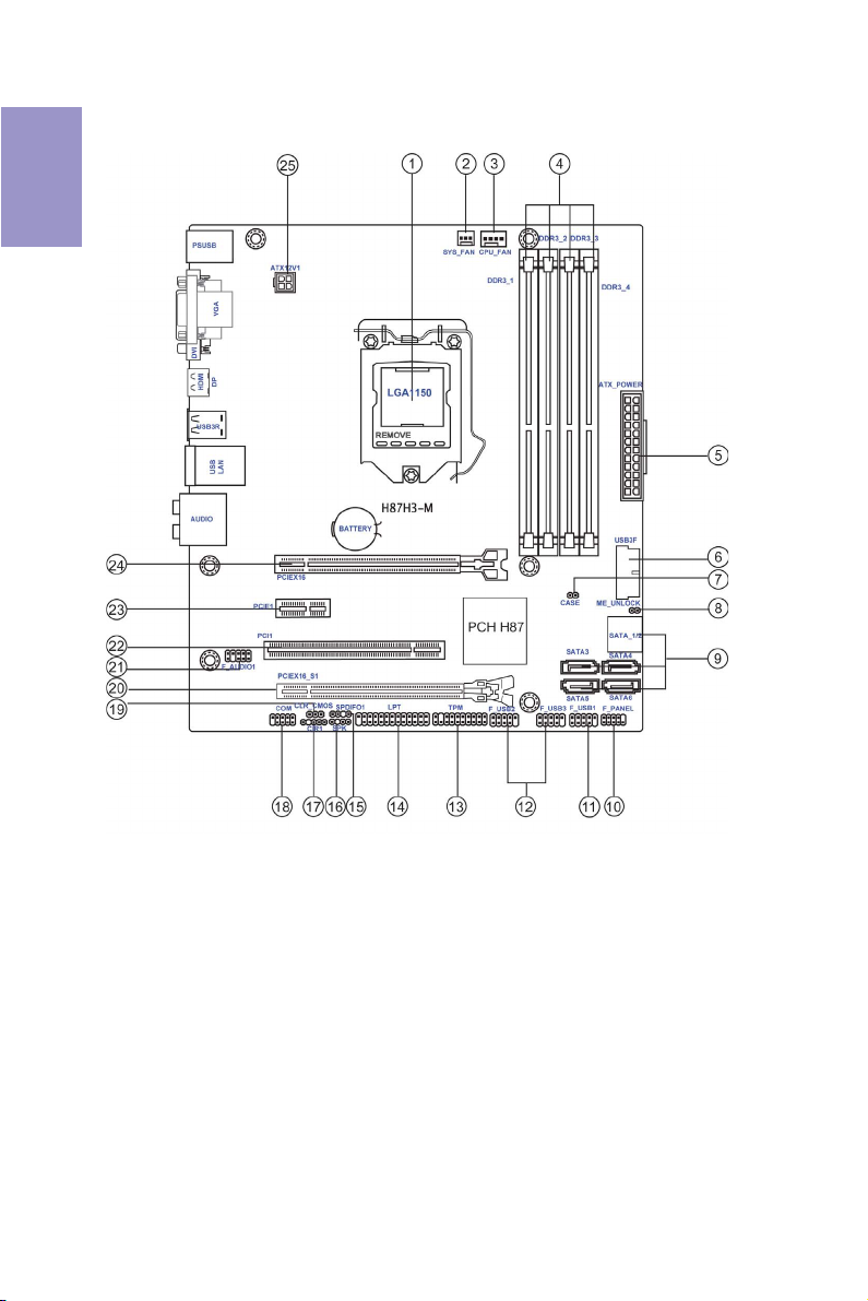
Motherboard Components
4
H87H3-M USER MANUAL
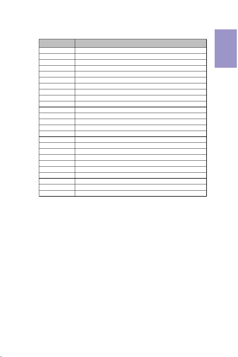
Table of Motherboard Components
LABEL COMPONENTS
1. CPU Socket
2. SYS_FAN 3-pin system cooling fan connector
3. CPU_FAN 4-pin CPU cooling fan connector
4. DDR3_1~4 240-pin DDR3 Module slots
5. ATX_POWER Standard 24-pin ATX power connector
6. USB3F Front panel USB 3.0 header
7. CASE CASE open header
8. ME_UNLOCK ME unlock header-for factory use only
9. SATA1~6 Serial ATA 6Gb/s connectors
10. F_PANEL Front panel switch/LED header
11. F_USB1 Front panel USB 2.0 header (Gray header supports EZ Charger)
12. F_USB2~3 Front panel USB 2.0 headers
13. TPM Trusted platform module header
14. LPT Parallel port header
15. SPDIFO1 SPDIF out header
16. SPK Speaker header
17. CIR1 Consumer Infrared
18. COM Onboard serial port header
19. CLR_CMOS Clear CMOS jumper
20. PCIEX16_S1 PCI Express Gen2 x4 slot
21. F_AUDIO1 Front panel audio header
22. PCI1 32-bit PCI add-on card slot
23. PCIE1 PCI Express Gen2 x1 slot
24. PCIEX16 PCI Express Gen3 x16 slot for graphics interface
25. ATX12V 4-pin +12V power connector
LGA1150 socket for Intel
®
4th Genera tion CoreTM Famil y processors
Chapter 1
H87H3-M USER MANUAL
5
Chapter 1
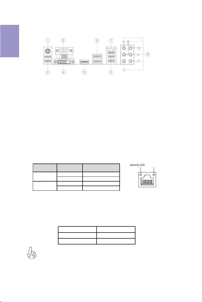
I/O Ports
1. PS/2 Combo port
Use the PS/2 combo port to connect the PS/2 Keyboard or PS/2 Mouse.
2. USB 2.0 Ports
Use the USB 2.0 ports to connect USB 2.0 devices.
3. VGA Port
Connect your monitor to the VGA port.
4. DVI Port
Connect your monitor to the DVI port.
5. HDMI Port
You can connect the display device to the HDMI port.
6. USB 3.0 Ports
Use the USB 3.0 ports to connect USB 3.0 devices.
7. LAN Port
Connect an RJ-45 jack to the LAN port to connect your computer to the Network.
8. Audio Ports
Use the audio jacks to connect audio devices. The D port is for stereo line-in signal,
while the F port is for microphone in signal. This motherboard supports 8-channel
audio devices that correspond to the A, B, C, and E port respectively. In addition, all
of the 3 ports, B, C, and E provide users with both right & left channels individually.
Users please refer to the following note for specific port function definition.
LAN LED Status Description
Activity LED
Link LED
OFF No d ata
Orange blinking Active
OFF No link
Green Link
Link LED
LAN Port
A: Center & Woofer D: Line-in
B: Ba ck Sur rou nd E: Fro nt Out
C: Sid e Surround F: Mic_in R ear
The above port definition can be changed to audio input or audio output by
changing the driver utility setting.
6
H87H3-M USER MANUAL
Chapter 2
Installing the Motherboard
2-1. Safety Precautions
Follow these safety precautions when installing the motherboard:
• Wear a grounding strap attached to a grounded device to avoid damage
from static electricity.
• Discharge static electricity by touching the metal case of a safely grounded
object before working on the motherboard.
• Leave components in the static-proof bags.
• Always remove the AC power by unplugging the power cord from the power
outlet before installing or removing the motherboard or other hardware
components.
2-2. Installing the motherboard in a Chassis
This motherboard carries a Micro ATX form factor of 244 x 220 mm. Choose a chassis
that accommodates this from factor. Make sure that the I/O template in the chassis
matches the I/O ports installed on the rear edge of the motherboard. Most system
chassis have mounting brackets installed in the chassis, which corresponds to the
holes in the motherboard. Place the motherboard over the mounting brackets and
secure the motherboard onto the mounting brackets with screws.
Chapter 2
Do not over-tighten the screws as this can stress the motherboard.
H87H3-M USER MANUAL
7
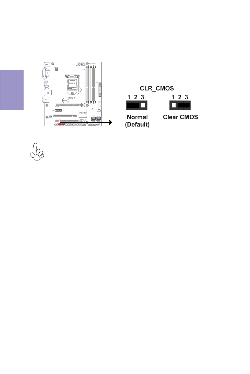
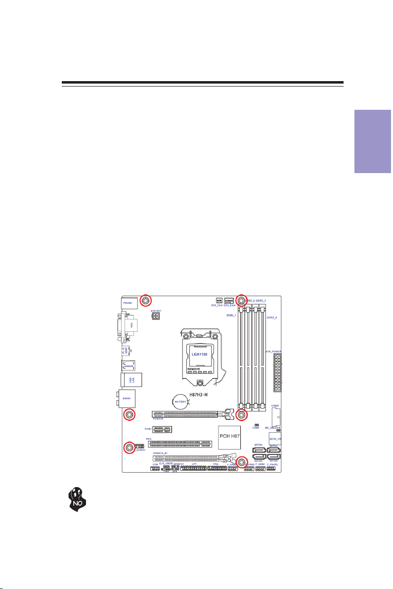
2-3. Checking Jumper Settings
The following illustration shows the location of the motherboard jumpers. Pin 1 is
labeled.
Chapter 2
To avoid the system instability after clearing CMOS, we recommend users to
enter the main BIOS setting page to “Load Default Settings” and then “Save
and Exit Setup”.
8
H87H3-M USER MANUAL
2-4. Installing Hardware
2-4-1. Installing the Processor
• This motherboard has an LGA1150 socket.
• When choosing a processor, consider the performance requirements of
the system. Performance is based on the processor design, the clock speed
and system bus frequency of the processor, and the quantity of internal
cache memory and external cache memory.
• You may be able to change the settings in the system Setup Utility. We
strongly recommend you do not over-clock processor or other components to run faster than their rated speed.
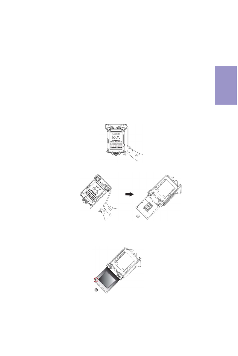
• The following illustration shows CPU installation components.
A. Press the hook of lever down with your thumb and pull it to the right
side to release it from retention tab.
B. Lift the tail of the load lever and rotate the load plate to fully open
position.
Chapter 2
C. Grasp the edge of the package substrate. Make sure pin 1 indicator
is on your bottom-left side. Aim at the socket and place the package
carefully into the socket by purely vertical motion.
H87H3-M USER MANUAL
9
Chapter 2
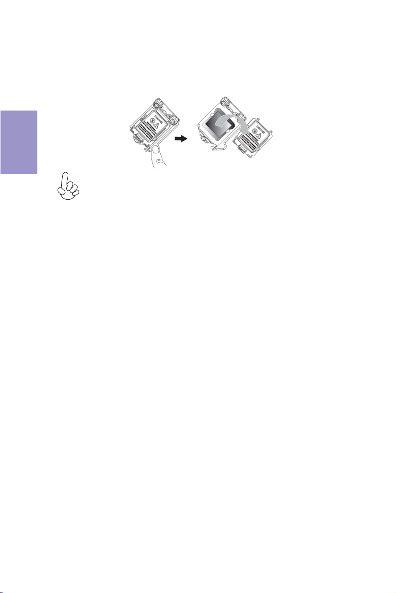
D. Rotate the load plate onto the package IHS (Intergraded Heat
Spreader). Engage the load lever while pressing down lightly onto the
load plate. Secure the load lever with the hook under retention tab. Then
the cover will flick automatically.
Please save and replace the cover onto the CPU socket if processor is removed.
10
H87H3-M USER MANUAL
2-4-2. Installing the CPU Cooler
• Install the cooling fan in a well-lit work area so that you can clearly see the
motherboard and processor socket.
• Avoid using cooling fans with sharp edges in case the fan casing and the
clips cause serious damage to the motherboard or its components.
• To achieve better airflow rates and heat dissipation, we suggest that you
use a high quality fan with 3800 rpm at least. CPU fan and heat sink installation procedures may vary with the type of CPU fan/heatsink supplied.
The form and size of fan/heatsink may also vary.
• DO NOT remove the CPU cap from the socket before installing a CPU.
• Return Material Authorization (RMA) requests will be accepted only if the
motherboard comes with the cap on the LGA1150 socket.
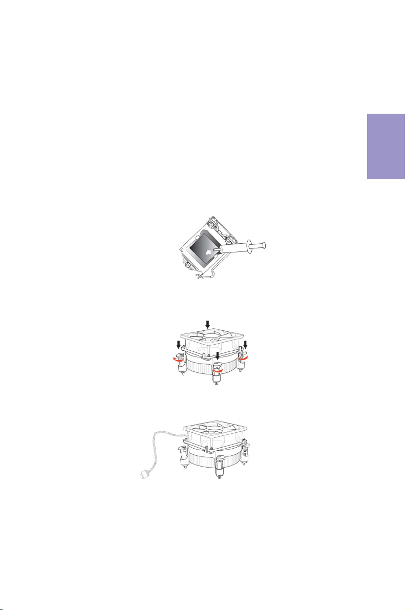
• The following illustration shows how to install CPU fan.
A. Apply some thermal grease onto the contacted area between the
heatsink and the CPU, and make it to be a thin layer.
B. Fasten the cooling fan supporting base onto the CPU socket on the
motherboard. And make sure the CPU fan is plugged to the CPU fan
connector.
Chapter 2
C. Connect the CPU cooler power connector to the CPU_FAN connector.
H87H3-M USER MANUAL
11
2-4-3. Installing Memory Modules
Chapter 2
• This motherboard accommodates four memory modules. It can support
four 240-pin DDR3 1600/1333 MHz.
• Do not remove any memory module from its antistatic packaging until
you are ready to install it on the motherboard. Handle the modules only
by their edges. Do not touch the components or metal parts. Always wear
a grounding strap when you handle the modules.
• You must install at least one module in any of the four slots. Total memory
capacity is 32 GB.
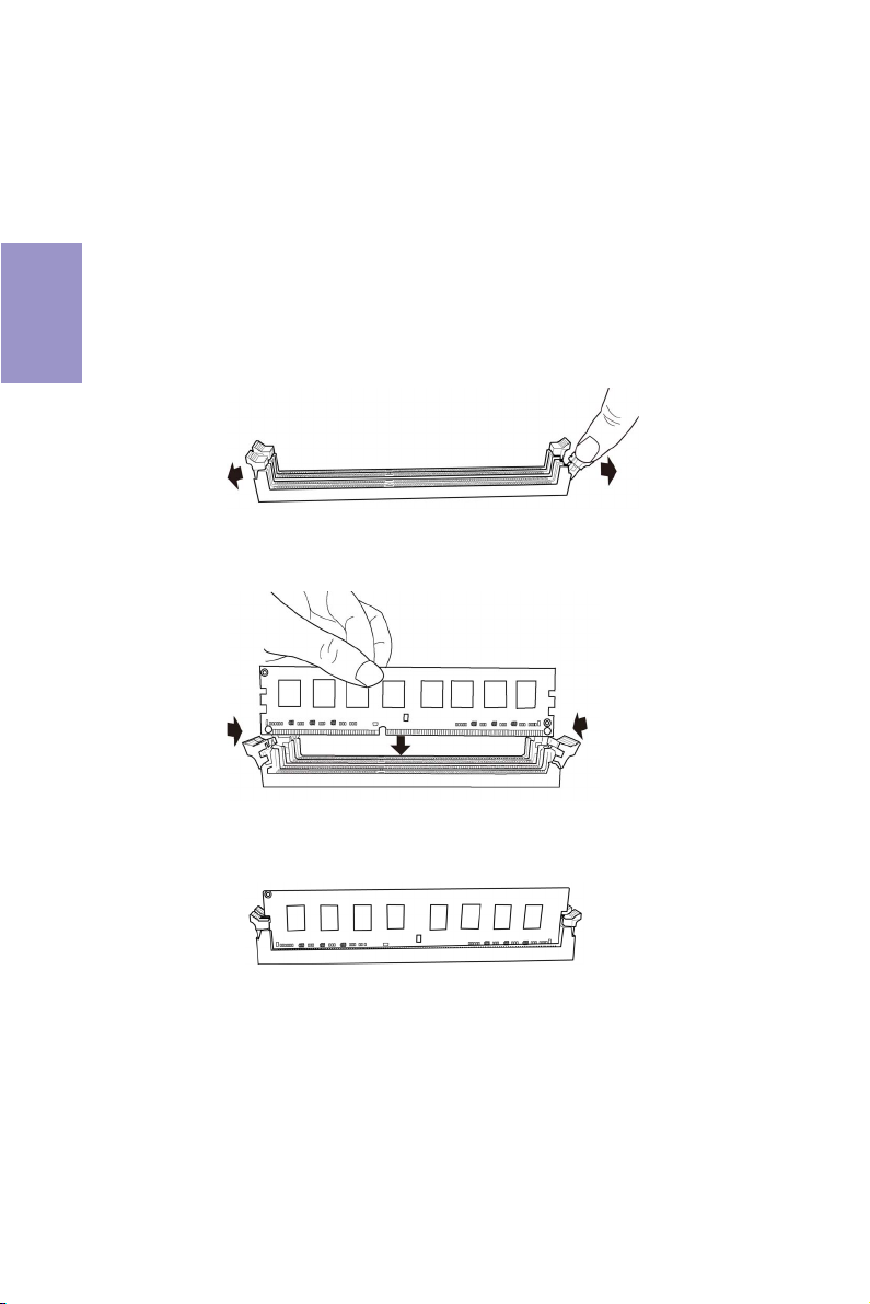
• Refer to the following to install the memory modules.
A. Push the latches on each side of the DIMM slot down.
B. Install the DIMM module into the slot and press it firmly down until it
seats correctly. Check that the cutouts on the DIMM module edge
connector match the notches in the DIMM slot.
C. The slot latches are levered upwards and latch on to the edges of the
DIMM.
The four DDR3 memory sockets (DDR3_1, DDR3_2, DDR3_3 and DDR3_4) are divided
into two channels and each channel has two memory sockets as following:
Channel A: DDR3_1, DDR3_2
Channel B: DDR3_3, DDR3_4
12
H87H3-M USER MANUAL
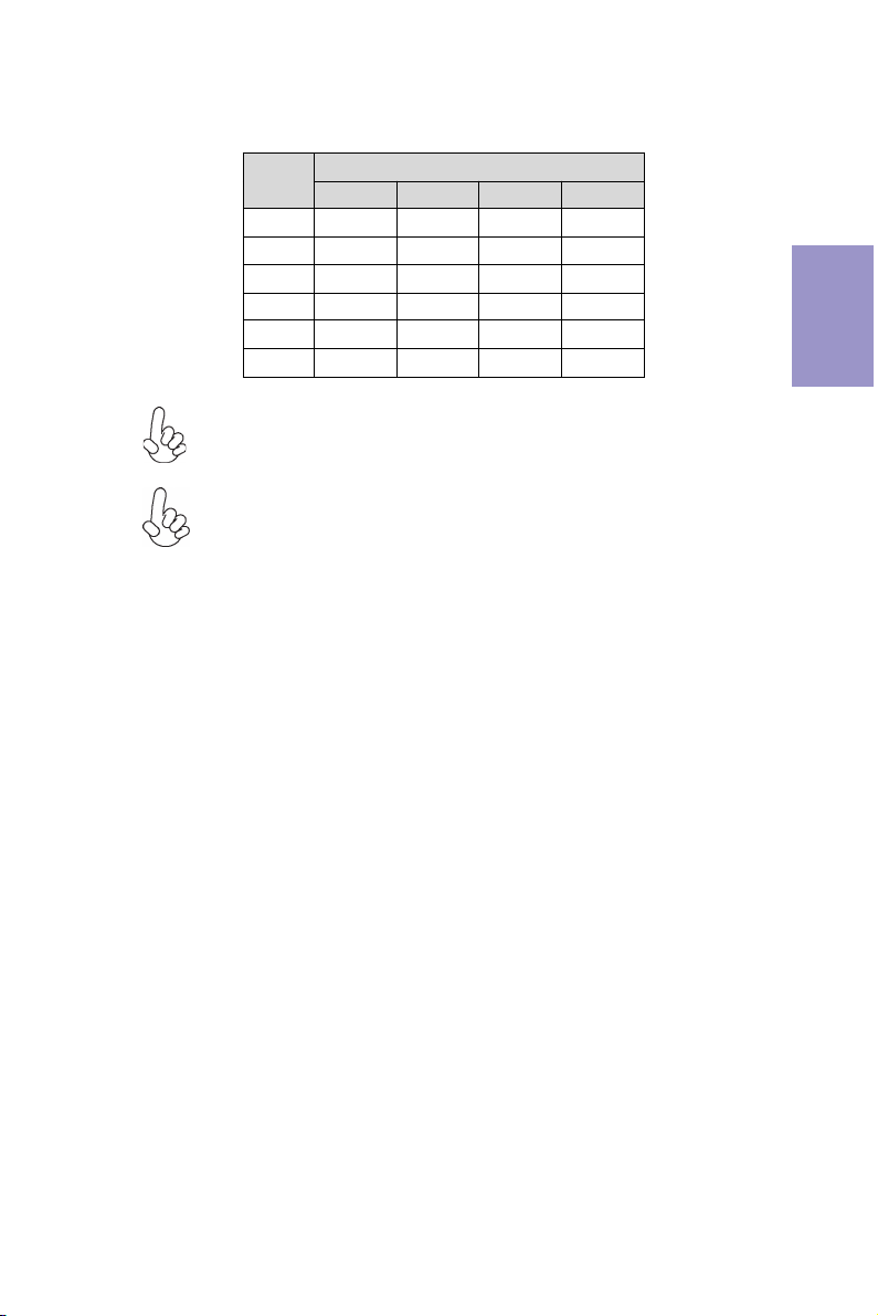
Recommend memory configuration
Model
1 DIMM ~ Populated ~ ~
1 DIMM ~ ~ ~ Populated
2 DIMMs ~ Populated ~ Populated
3 DIMMs Populated Populated ~ Populated
3 DIMMs ~ Populated Populated Populated
4 DIMMs Populated Populated Populated Populated
Due to Intel CPU spec definition, please follow the table above for
recommended memory configuration.
1. For best performance and compatibility, we recommend that users give
priority to the white DIMMs (DDR3_2/DDR3_4) when installing DIMMs.
2. We suggest users not to mix memory type. It is recommended to use the
same brand and type memory on this motherboard.
DDR3_1 DDR3_2 DDR3_3 DDR3_4
Sockets
Chapter 2
H87H3-M USER MANUAL
13
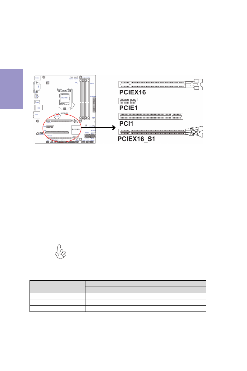
2-4-4. Installing Add-on Cards
The slots on this motherboard are designed to hold expansion cards and connect
them to the system bus. Expansion slots are a means of adding or enhancing the
motherboard’s features and capabilities. With these efficient facilities, you can
increase the motherboard’s capabilities by adding hardware that performs tasks
Chapter 2
that are not part of the basic system.
PCIEX16 Slot The PCI Express x16 slot is used to install an external PCI Ex-
PCIE1 Slot
PCI1 Slot
PCIEX16_S1 Slot This slot is fully compliant to the PCI Express Base Specification
Recommend add_on card configuration
Model
SPEC PCI-E Gen.3 Runni ng x16 mode PCI-E Gen.2 Runni ng x4 mode
Color Gray Black
1 Graphic Ca rd (VGA card) Populated --
press graphics card that is fully compliant to the PCI Express
Base Specification revision 3.0.
The PCI Express x1 slot is fully compliant to the PCI Express Base
Specification revision 2.0.
This motherboard is equipped with one standard PCI slot. PCI
stands for Peripheral Component Interconnect and is a bus
standard for expansion cards, which for the most part, is a
supplement of the older ISA bus standard. The PCI slot on this
board is PCI v3.0 compliant.
revision 2.0 which runs at x4 mode.
Before installing an add-on card, check the documentation for
the card carefully. If the card is not Plug and Play, you may have
to manually configure the card before installation.
PCIEX16 Slots
PCIEX16 PCIEX16_S1
14
H87H3-M USER MANUAL
Follow these instructions to install an add-on card:
1 Remove a blanking plate from the system case corresponding to the slot
you are going to use.
2 Install the edge connector of the add-on card into the expansion slot.
Ensure that the edge connector is correctly seated in the slot.
3 Secure the metal bracket of the card to the system case with a screw.
1. For some add-on cards, for example graphics adapters and network adapters, you have to install drivers and software before you can begin using the
add-on card.
2. The onboard PCI interface does not support 64-bit SCSI cards.
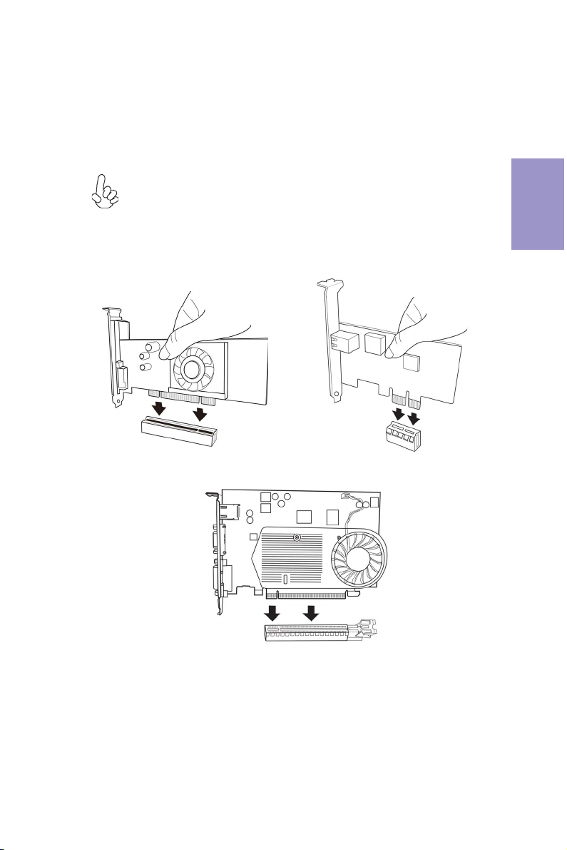
Please refer the following illustrations to install the add-on card:
Chapter 2
Install the VGA Card in the PCI slot
Install the VGA Card in the PCIE X16 slot
H87H3-M USER MANUAL
Install the LAN Card in the PCIE X1 slot
15
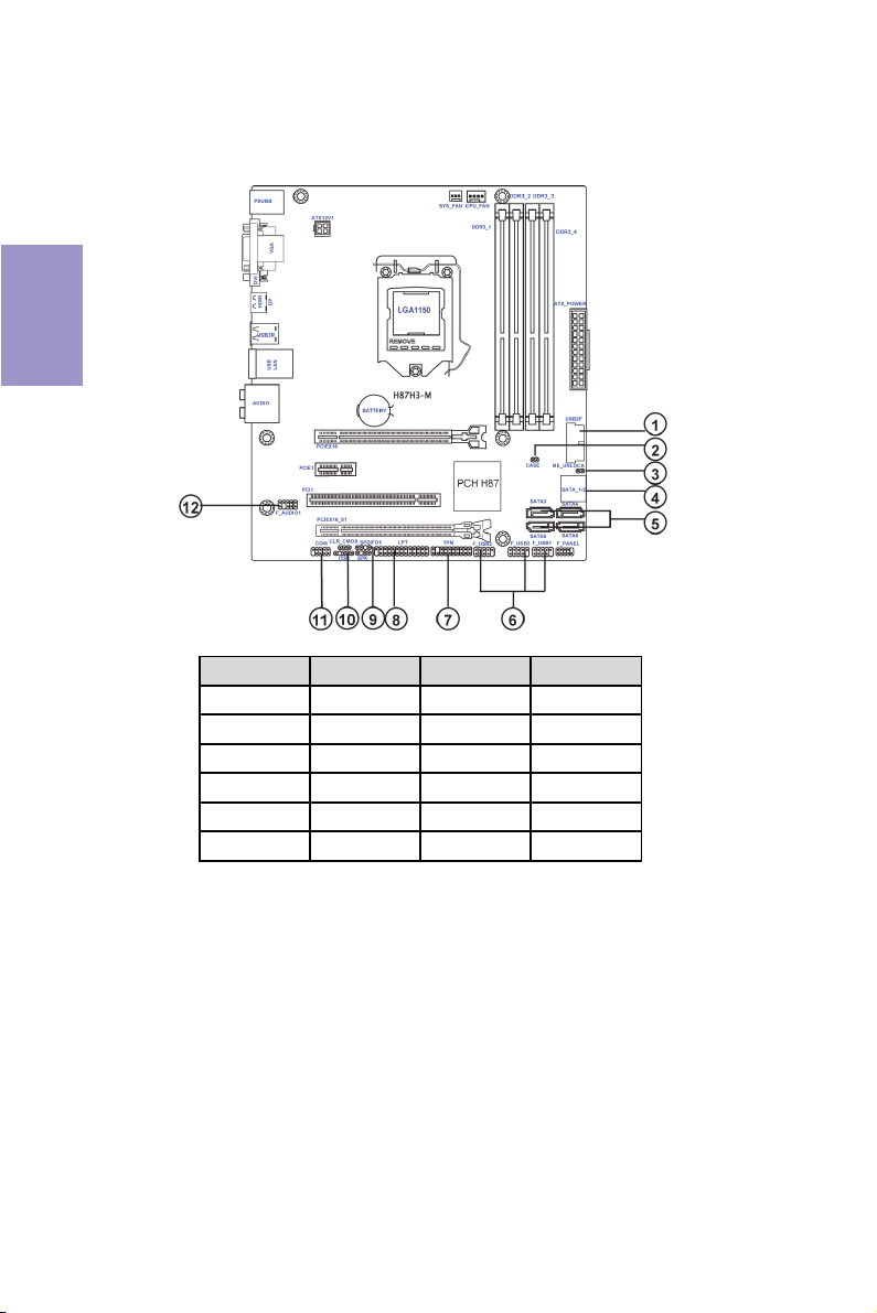
2-4-5. Connecting Optional Devices
Refer to the following for information on connecting the motherboard’s optional
devices:
Chapter 2
No. Components No. Components
1USB3F 7 TPM
2CASE8 LPT
3 ME_UNLOCK 9 SPDIFO1
4 SATA1~2 10 CI R1
5 SATA3~6 11 COM
6 F_USB1~3 12 F_AUDIO1
16
H87H3-M USER MANUAL
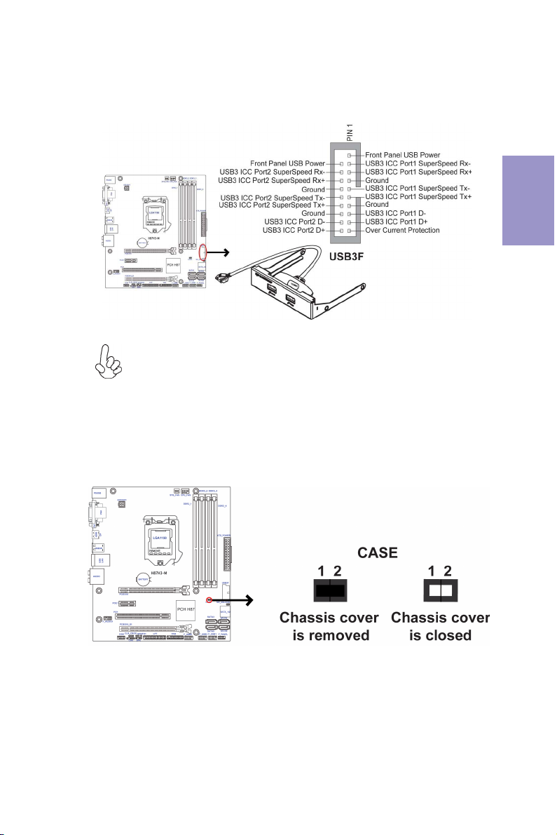
1. USB3F: Front Panel USB 3.0 header
This Motherboard implements one USB 3.0 header supporting 2 extra front USB 3.0
ports, which delivers 5Gb/s transfer rate.
Please make sure that the USB cable has the same pin assignment as indicated above. A different pin assignment may cause damage or system hangup.
2. CASE: Chassis Intrusion Detect Header
This detects if the chassis cover has been removed. This function needs a chassis
equipped with instrusion detection switch and needs to be enabled in BIOS.
Chapter 2
H87H3-M USER MANUAL
17

3. ME_UNLOCK: ME Unlock Header
Chapter 2
4 & 5. SATA1~6: Serial ATA connectors
SATA1~6 connectors are used to support the Serial ATA 6.0Gb/s device, simpler disk
drive cabling and easier PC assembly. It eliminates limitations of the current Parallel ATA interface. But maintains register compatibility and software compatibility
with Parallel ATA.
18
H87H3-M USER MANUAL
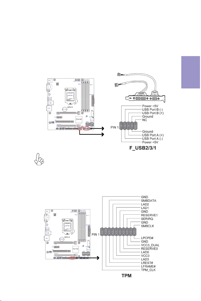
6. F_USB1~3: Front Panel USB 2.0 headers
The motherboard has three USB 2.0 headers supporting six USB 2.0 ports. Additionally, some computer cases have USB ports at the front of the case. If you have this
kind of case, use auxiliary USB connector to connect the front-mounted ports to the
motherboard.
Unlike F_USB2 & F_USB3, F_USB1 supports EZ Charger technology, provides 3 times
current than general USB port in off mode for USB devices. It is useful and excellent,
especially for the iPhone, iPad and iPod touch devices that need a large amount of
current for faster recharging within less time.
Please make sure that the USB cable has the same pin assignment as indicated above. A different pin assignment may cause damage or system hangup.
Chapter 2
7. TPM: Trusted Platform Module header
Trusted platform module (TPM) is a published specification detailing a
microcontroller that can store secured information, and implementations of that
specification.
H87H3-M USER MANUAL
19
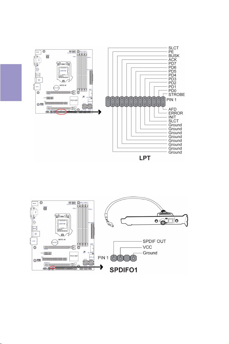
8. LPT: Onboard parallel port header
This is a header that can be used to connect to the printer, scanner or other devices.
Chapter 2
9. SPDIFO1: SPDIF out header
This is an optional header that provides an SPDIFO (Sony/Philips Digital Interface)
output to digital multimedia device through optical fiber or coaxial connector.
20
H87H3-M USER MANUAL
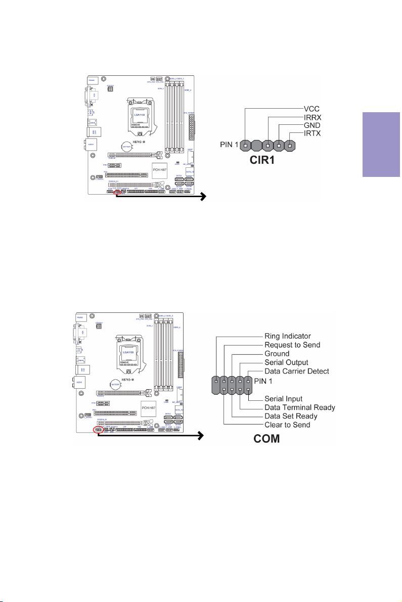
10. CIR: Consumer Infrared Header
11. COM: Onboard serial port header
Connect a serial port extension bracket to this header to add a serial port to your
system.
Chapter 2
H87H3-M USER MANUAL
21
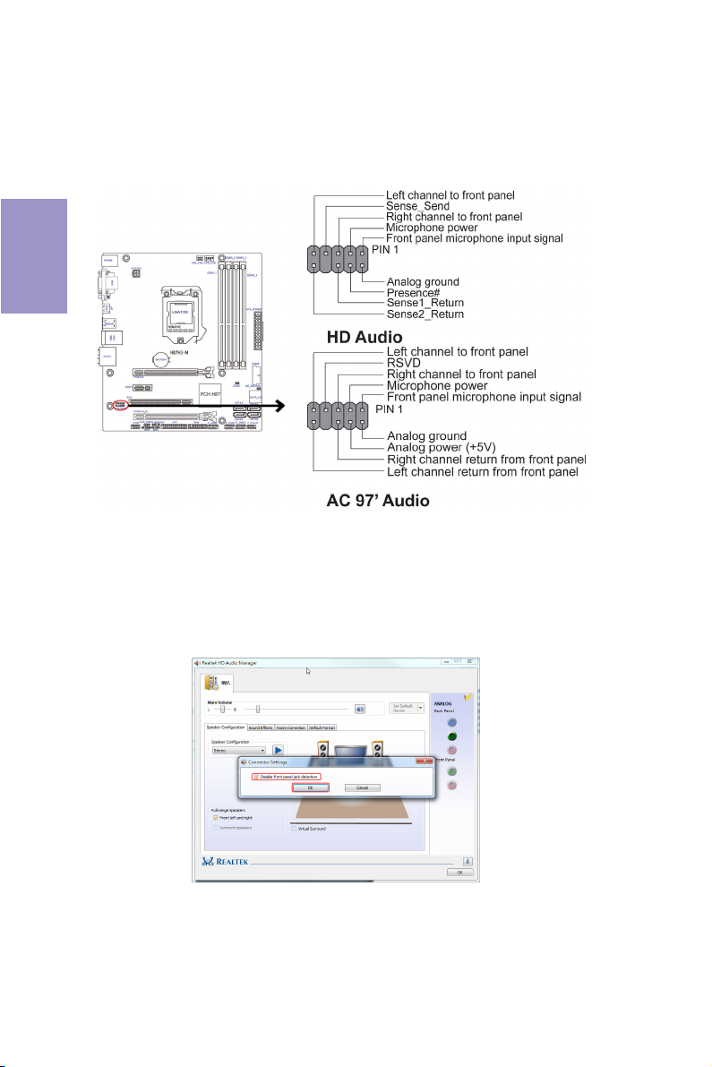
12. F_AUDIO1: Front Panel Audio Header
The front panel audio header allows the user to install auxiliary front-oriented microphone and line-out ports for easier access. This header supports HD audio by
default. If you want connect an AC
please set as below picture.
Chapter 2
AC’ 97 Audio Configuration: To enable the front panel audio connector to
support AC97 Audio mode.
If you use AC’ 97 Front Panel, please tick off the option of “Disabled Front Panel
Detect
Detect
’ 97 front panel audio to HD onboard headers,
”. If you use HD Audio Front Panel, please don’ t tick off “Disabled Front Panel
” .
22
* For reference only
H87H3-M USER MANUAL
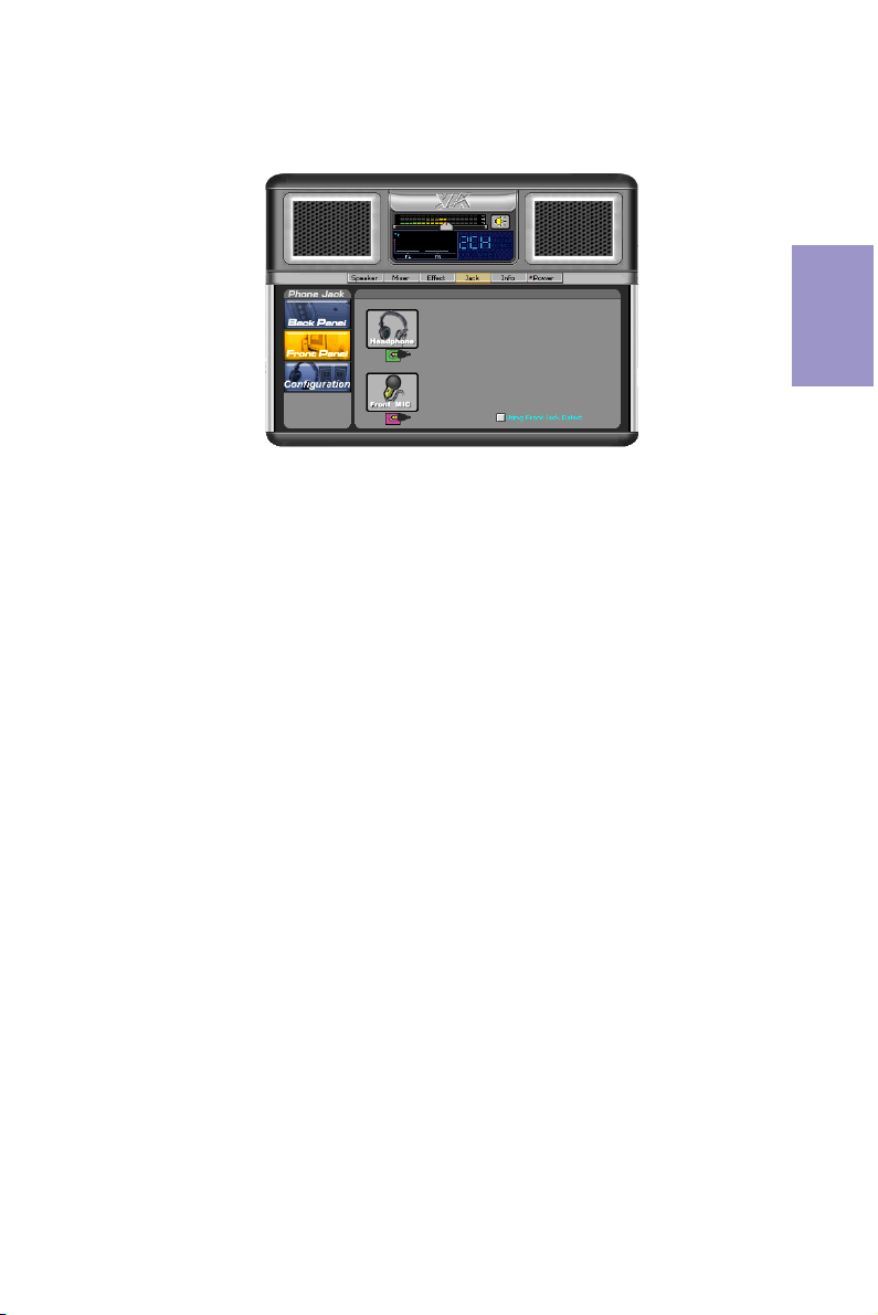
If you use AC’ 97 Front Panel, please don’ t tick off “ Using Front Jack Detect ” . If you
use HD Audio Front Panel, please
tick off the option of “Using Front Jack Detect ” .
* For reference only
Chapter 2
H87H3-M USER MANUAL
23
 Loading...