


iii

iv
Preface
Copyright
This publication, including all photographs, illustrations and software, is protected under international copyright laws, with all rights reserved. Neither this manual, nor any of the material contained herein, may be reproduced without written consent of the author.
Version 1.0b
Disclaimer
The information in this document is subject to change without notice. The manufacturer makes no representations or warranties with respect to the contents hereof and specifically disclaims any implied warranties of merchantability or fitness for any particular purpose. The manufacturer reserves the right to revise this publication and to make changes from time to time in the content hereof without obligation of the manufacturer to notify any person of such revision or changes.
Trademark Recognition
Microsoft, MS-DOS and Windows are registered trademarks of Microsoft Corp.
MMX, Pentium, Pentium-II, Pentium-III, Celeron are registered trademarks of Intel Corporation.
Other product names used in this manual are the properties of their respective owners and are acknowledged.
Federal Communications Commission (FCC)
This equipment has been tested and found to comply with the limits for a Class B digital device, pursuant to Part 15 of the FCC Rules. These limits are designed to provide reasonable protection against harmful interference in a residential installation. This equipment generates, uses, and can radiate radio frequency energy and, if not installed and used in accordance with the instructions, may cause harmful interference to radio communications. However, there is no guarantee that interference will not occur in a particular installation. If this equipment does cause harmful interference to radio or television reception, which can be determined by turning the equipment off and on, the user is encouraged to try to correct the interference by one or more of the following measures:
•Reorient or relocate the receiving antenna
•Increase the separation between the equipment and the receiver
•Connect the equipment onto an outlet on a circuit different from that to which the receiver is connected
•Consult the dealer or an experienced radio/TV technician for help
Shielded interconnect cables and a shielded AC power cable must be employed with this equipment to ensure compliance with the pertinent RF emission limits governing this device. Changes or modifications not expressly approved by the system’s manufacturer could void the user’s authority to operate the equipment.
Preface
ii
Declaration of Conformity
This device complies with part 15 of the FCC rules. Operation is subject to the following conditions:
•This device may not cause harmful interference, and
•This device must accept any interference received, including interference that may cause undesired operation
Canadian Department of Communications
This class B digital apparatus meets all requirements of the Canadian Interference-causing Equipment Regulations.
Cet appareil numérique de la classe B respecte toutes les exigences du Réglement sur le matériel brouilieur du Canada.
About the Manual
The manual consists of the following:
Chapter 1
Introducing the Motherboard
Chapter 2
Installing the Motherboard
Chapter 3
Using BIOS
Chapter 4
Using the Motherboard Software
Describes features of the motherboard. Go to H page 1
Describes installation of motherboard components.
Go to H page 7
Provides information on using the BIOS Setup Utility.
Go to |
H page 25 |
Describes the motherboard software
Go to |
H page 47 |
Preface

iii
TABLE OF CONTENTS |
|
Preface |
i |
Chapter 1 |
1 |
Introducing the Motherboard |
1 |
Introduction................................................................................................. |
1 |
Feature.......................................................................................................... |
2 |
Motherboard Components........................................................................ |
4 |
Chapter 2 |
7 |
Installing the Motherboard |
7 |
Safety Precautions...................................................................................... |
7 |
Choosing a Computer Case....................................................................... |
7 |
Installing the Motherboard in a Case...................................................... |
7 |
Checking Jumper Settings......................................................................... |
8 |
Setting Jumpers.............................................................................. |
8 |
Checking Jumper Settings.............................................................. |
9 |
Jumper Settings.............................................................................. |
9 |
Connecting Case Components............................................................... |
10 |
Front Panel Header..................................................................... |
12 |
Installing Hardware................................................................................... |
13 |
Installing the Processor............................................................... |
13 |
Installing Memory Modules......................................................... |
15 |
Installing a Hard Disk Drive/CD-ROM/SATA Hard Drive........ |
17 |
Installing a Floppy Diskette Drive............................................... |
18 |
Installing Add-on Cards.............................................................. |
19 |
Connecting Optional Devices...................................................... |
20 |
Connecting I/O Devices.......................................................................... |
24 |
Chapter 3 |
25 |
Using BIOS |
25 |
About the Setup Utility............................................................................ |
25 |
The Standard Configuration........................................................ |
25 |
Entering the Setup Utility.............................................................. |
25 |
Updating the BIOS....................................................................... |
27 |
Using BIOS................................................................................................ |
27 |
Standard CMOS Features........................................................... |
28 |
Advanced BIOS Features............................................................. |
30 |
Advanced Chipset Features......................................................... |
33 |
iv
Integrated Peripherals................................................................. |
35 |
Power Management Setup........................................................... |
39 |
PNP/PCI Configurations............................................................. |
41 |
PC Health Status.......................................................................... |
42 |
Frequency Control....................................................................... |
43 |
Load Fail-Safe Defaults............................................................... |
44 |
Load Optimized Defaults Option................................................. |
43 |
Set Password............................................................................... |
44 |
Save & Exit Setup......................................................................... |
45 |
Exit Without Saving....................................................................... |
45 |
Chapter 4 |
47 |
Using the Motherboard Software |
47 |
About the Software CD-ROM................................................................ |
47 |
Auto-installing under Windows 2000/XP............................................. |
47 |
Running Setup.............................................................................. |
48 |
Manual Installation.................................................................................. |
50 |
Utility Software Reference....................................................................... |
50 |
Multi-Language Translation

1
Chapter 1
Introducing the Motherboard
Introduction
Thank you for choosing the motherboard. This motherboard is a high performance, enhanced function motherboard designed to support the LGA775 socket Intel Pentium 4/ Celeron D/Pentium D processors for high-end business or personal desktop markets.
The motherboard incorporates the 945G Northbridge (NB) and ICH7 Southbridge (SB) chipsets. The Northbridge supports a Front Side Bus (FSB) frequency of 1066/800/533 MHz using a scalable FSB Vcc_CPU. The memory controller supports DDR2 memory DIMM frequencies of 667/533/400. It supports two DDR Sockets with up to maximum memory of 2 GB. DDR memory bandwidth of 5.3GB/s in single-channel is supported, or 10.7GB/s in dual-channel interleaved mode assuming DDR2 667 MHz. High resolution graphics via one PCI Express slot, intended for Graphics Interface, is fully compliant to the PCI Express Base Specification revision 1.0a.
The ICH7 Southbridge supports two PCI slots which are PCI 2.3 compliant. In addition, one PCI Express x1 slot is supported, fully compliant to the PCI Express Base Specification, Revision 1.0a. It implements an EHCI compliant interface that provides 480Mb/s bandwidth for eight USB 2.0 ports, integrates Azalia codec supporting Azilia standard that features an 8-channel High Definition Audio output. One onboard IDE connector supports 2 IDE devices in Ultra ATA100/66/33 mode. The Southbridge integrates a Serial ATA host controller that is SATA II compliant, supporting four SATA ports with maximum transfer rate up to 300 MB/s each.
The motherboard is equipped with advanced full set of I/O ports in the rear panel, including PS/2 mouse and keyboard connectors, COM1, LPT1, one VGA port, four USB ports, one optional LAN port, one optional 1394 port and audio jacks for microphone, line-in and 8- ch line out.
Introducing the Motherboard
2
Feature
Processor
The motherboard uses an LGA775 type of Pentium 4/Celeron D/Pentium D that
carries the following features:
•Accommodates Intel Pentium 4/Celeron D/Pentium D processors
•Supports a system bus (FSB) of 1066/800/533MHz
•Supports “Hyper-Threading” technology CPU
“Hyper-Threading” technology enables the operating system into thinking it’s hooked up to two processors, allowing two threads to be run in parallel, both on separate “logical” processors within the same physical processor.
Chipset
The 945G Northbridge (NB) and ICH7 Southbridge (SB) chipsets are based on an innovative and scalable architecture with proven reliability and performance.
945G (NB) |
• |
Supports 32-bit host bus addressing, allowing the CPU to |
|
|
access the entire 4 GB of the memory address space. |
|
• |
2 GB/s point-to-point Direct Media Interface (DMI) to ICH7 (1 |
|
|
GB/s)each direction. |
|
• |
Supports one PCI Express x16 for Graphics Interface, fully |
|
|
compliant to the PCI Express Base Specification revision |
|
|
1.0a. |
|
• |
Supports 256-Mb, 512-Mb and 1-Gb DDR2 technologies for |
|
|
x8 and x16 devices |
|
• |
Supports high quality 3D setup, Render Engine and high- |
|
|
quality texture engine |
ICH7 (SB) |
• |
Enhanced DMA Controller, interrupt controller, and timer func- |
|
|
tions |
|
• |
Compliant with PCI Express Base Specification, Revision |
|
|
1.0a |
|
• |
Compliant with PCI 2.3 specificaiton |
|
• |
Compliant with Serial ATA II specification |
|
• |
Integrated USB 2.0 Host Controller supporting up to eight |
|
|
USB 2.0 ports |
|
• |
Integrated LAN controller |
|
• |
Compliant with AC’97/Intel High Definition Audio Codec(s) |
|
|
supporting 8-channel audio outputs |
Memory |
• |
Integrated IDE controller supports Ultra ATA100/66/33 |
•Supports DDR2 667/533/400 DDR SDRAM with Dual-channel DDR2 architecture
•Accommodates two unbuffered DIMMs
•Up to 1 GB per DIMM with maximum memory size up to 2 GB
Graphics
•3D Setup and Render Engine
•Zone Rendering Support
•High Quality Texture Engine
1394a FireWire (Optional)
Introducing the Motherboard

3
•Fully compliant with provisions of IEEE Std 1394-1995 for a high-performance serial bus and IEEE Std 1394a-2000
•Two IEEE Std 1394a-2000 fully compliant cable ports at 100/200/400 Mb/s
Onboard LAN (Optional)
The onboard LAN controller provides the following features:
•Integrated 10/100/1000 transceiver
•Supports PCI v2.3, 32-bit, 33/66MHz
•Supports fully with IEEE802.3, IEEE802.3u and IEEE802.3ab
Audio
•Compliant with Intel High Definition Audio, supporting 8-channel DACs with
95dB S/N ratio
•Compabilities: 192/96/48/44.1 KHz with 24/20/16 bits
•Power support: Digital: 3.3V; Analog: 3.3V/5.0V
•All analog jacks are stereo input and output re-tasking for analog plug & play
•Meets Micrsoft WHQL/WLP 2.0 audio requirements
•Direct Sound 3DTM compatible
•Dolby Digital Encorder output for consumer electronic application
Expansion Options
The motherboard comes with the following expansion options:
•One PCI Express x16 slot for Graphic Interface
•One PCI Express x1 slot
•Two 32-bit PCI v2.3 compliant slots
•One 40-pin IDE low profile header that support two IDE devices
•One floppy disk drive interface
•Four 7-pin SATA connectors
The motherboard supports UltraDMA bus mastering with transfer rates of 100/66 MB/s.
Integrated I/O
The motherboard has a full set of I/O ports and connectors:
•Two PS/2 ports for mouse and keyboard
•One serial port
•One parallel port
•One VGA port
•Four USB ports
•One 1394 port (optional)
•One LAN port (optional)
•Audio jacks for microphone in, line-in and 8-ch High Definition Audio output
BIOS Firmware
This motherboard uses Award BIOS that enables users to configure many system features including the following:
•Power management
•Wake-up alarms
•CPU parameters
•CPU and memroy timing
The firmware can also be used to set parameters for different processor clock speeds.
Some hardware specifications and software items are subject to change with out prior notice.
Introducing the Motherboard
4
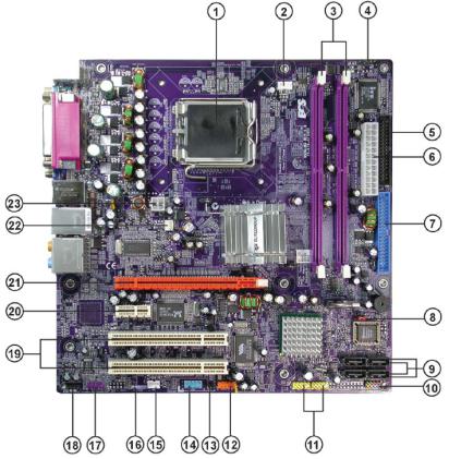
Motherboard Components
Introducing the Motherboard
5
Table of Motherboard Components
|
|
LABEL |
COMPONENT |
|
1 CPU Socket |
LGA775 socket for Pentium 4/PentiumD CPUs |
|
|
2 CPU_FAN |
CPU cooling fan connector |
|
|
3 DIMM1~2 |
240-pin DDR2 SDRAM slots |
|
|
4 IRDA |
Infrared header |
|
5 |
FDD |
Floppy diskette drive connector |
|
6 |
ATX1 |
Standard 24-pin ATX power connector |
|
|
7 IDE1 |
Primary IDE channel |
|
8 |
CLR_CMOS |
Clear CMOS jumper |
|
|
9 SATA1~4 |
Serial ATA connectors |
|
|
10 PANEL1 |
Panel connector for case switches and LEDs |
|
|
11 USB1-2 |
Front Panel USB headers |
|
12 |
1394A2 |
IEEE 1394a header |
|
13 |
BIOS_WP |
BIOS flash protect jumper |
|
14 |
COM2* |
Onboard Serial port hader |
|
15 |
WOL1* |
Wake On LAN connector |
|
|
16 S/PDIF |
SPDIF out header |
|
|
17 |
F_AUDIO |
Front panel audio header |
18 |
AUX_IN* |
Auxiliary In connector |
|
|
19 PCI1~2 |
32-bit add-on card slots |
|
|
20 PCIE1 |
PCI Express x1 slot |
|
|
21 PCIEX16 |
PCI Express slot for graphics interface |
|
|
22 SYS_FAN |
System cooling fan connector |
|
|
23 ATX12V |
Auxiliary 4-pin power connector |
|
|
|
|
|
“*” stands for optional components
This concludes Chapter 1. The next chapter explains how to install the motherboard.
Introducing the Motherboard
6
Memo
Introducing the Motherboard

7
Chapter 2
Installing the Motherboard
Safety Precautions
•Follow these safety precautions when installing the motherboard
•Wear a grounding strap attached to a grounded device to avoid damage from static electricity
•Discharge static electricity by touching the metal case of a safely grounded object before working on the motherboard
•Leave components in the static-proof bags they came in
•Hold all circuit boards by the edges. Do not bend circuit boards
Choosing a Computer Case
There are many types of computer cases on the market. The motherboard complies with the specifications for the micro-ATX system case. First, some features on the motherboard are implemented by cabling connectors on the motherboard to indicators and switches on the system case. Make sure that your case supports all the features required. Secondly, this motherboard supports one or two floppy diskette drives and two enhanced IDE drives. Make sure that your case has sufficient power and space for all drives that you intend to install.
Most cases have a choice of I/O templates in the rear panel. Make sure that the I/O template in the case matches the I/O ports installed on the rear edge of the motherboard.
This motherboard carries an micro-ATX form factor of 244 x 244 mm. Choose a case that accommodates this form factor.
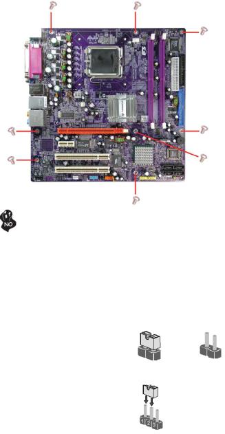
Installing the Motherboard in a Case
Refer to the following illustration and instructions for installing the motherboard in a case.
Most system cases have mounting brackets installed in the case, which correspond the holes in the motherboard. Place the motherboard over the mounting brackets and secure the motherboard onto the mounting brackets with screws.
Ensure that your case has an I/O template that supports the I/O ports and expansion slots on your motherboard.
Installing the Motherboard
8
Do not over-tighten the screws as this can stress the motherboard.
Checking Jumper Settings
This section explains how to set jumpers for correct configuration of the motherboard.
Setting Jumpers
Use the motherboard jumpers to set system configuration options. Jumpers with more than one pin are numbered. When setting the jumpers, ensure that the jumper caps are placed on the correct pins.
The illustrations show a 2-pin jumper. When |
|
|
the jumper cap is placed on both pins, the |
|
|
jumper is SHORT. If you remove the jumper |
|
|
cap, or place the jumper cap on just one pin, |
|
|
the jumper is OPEN. |
SHORT |
OPEN |
|
This illustration shows a 3-pin jumper. Pins 1 and 2 are SHORT
Installing the Motherboard
9
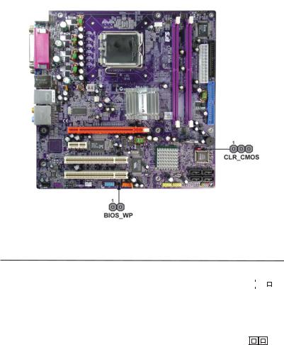
Checking Jumper Settings
The following illustration shows the location of the motherboard jumpers. Pin 1 is labeled.
Jumper Settings
Jumper |
Type |
Description |
Setting (default) |
|
|
|
|
CLR_CMOS |
3-pin |
CLR_CMOS |
1-2: NORMAL |
|
|
|
|
|
|
|
|
||||
2-3: CLEAR CMOS |
|
|
|
|
|||
|
|
|
|
|
|
|
|
|
|
|
|
|
|
|
|
|
|
|
|
|
|
|
|
|
|
|
Before clearing the |
1 |
|
|
|
|
|
|
CMOS, make sure to |
CLR_CMOS |
|||
|
|
|
turn off the system. |
|
|
|
|
BIOS_WP |
2-pin |
FLASH |
OPEN: WRITE UNPROTECT |
|
|
|
|
|
|
|
|
||||
|
|
|
SHORT: WRITE PROTECT |
BIOS_WP |
|||
|
|
|
|
||||
|
|
|
|
|
|
|
|
Installing the Motherboard
10
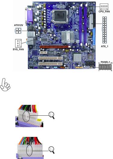
Connecting Case Components
After you have installed the motherboard into a case, you can begin connecting the motherboard components. Refer to the following:
1Connect the CPU cooling fan cable to CPU_FAN
2Connect the system cooling fan connector to SYS_FAN
3Connect the case switches and indicator LEDs to the PANEL1.
4Connect the standard power supply connector to ATX1.
5Connect the auxiliary case power supply connector to ATX12V.
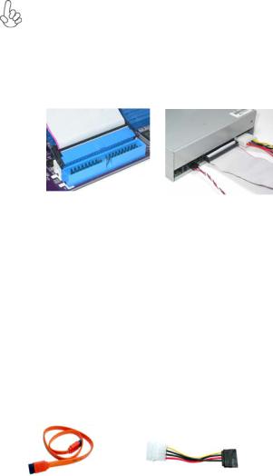
Connecting 20/24-pin power cable
Users please note that the 20-pin and 24-pin power cables can both be connected to the PWR1 connector. With the 20-pin power cable, just align the 20-pin power cable with the pin 1 of the ATX1 connector. However, using 20-pin power cable may cause the system to become unbootable or unstable because of insufficient electricity. A minimum power of 300W is recommended for a fully-config- ured system.
With ATX v1.x power supply, users please note that when installing 20-pin power cable, the latche of power cable falls on the left side of the ATX1 connector latch, just as the picture shows.
20-pin power cable
With ATX v2.x power supply , users please note that when installing 24-pin power cable, the latches of power cable and the ATX1 match perfectly.
24-pin power cable
Installing the Motherboard
11
CPU_FAN: FAN Power Connector
Pin |
Signal Name |
Function |
1 |
GND |
System Ground |
2 |
+12V |
Power +12V |
3 |
Sense |
Sensor |
4 |
PWM |
CPU FAN control |
Users please note that the fan connector supports the CPU cooling fan of 1.1A ~ 2.2A (26.4W max) at +12V.
SYS_FAN: FAN Power Connector
Pin |
Signal Name |
Function |
1 |
GND |
System Ground |
2 |
+12V |
Power +12V |
3 |
Sense |
Sensor |
ATX1: ATX 24-pin Power Connector
Pin |
Signal Name |
Pin |
Signal Name |
1 |
+3.3V |
13 |
+3.3V |
|
|
|
|
2 |
+3.3V |
14 |
-12V |
3 |
Ground |
15 |
Ground |
4 |
+5V |
16 |
PS_ON |
5 |
Ground |
17 |
Ground |
6 |
+5V |
18 |
Ground |
7 |
Ground |
19 |
Ground |
8 |
PWRGD |
20 |
-5V |
9 |
+5VSB |
21 |
+5V |
10 |
+12V |
22 |
+5V |
11 |
+12V |
23 |
+5V |
|
|
|
|
12 |
+3.3V |
24 |
Ground |
|
|
|
|
ATX12V: ATX 12V Power Connector
Pin Signal Name
1Ground
2Ground
3+12V
4+12V
Installing the Motherboard
12
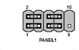
Front Panel Header
The front panel header (PANEL1) provides a standard set of switch and LED headers commonly found on ATX or Micro ATX cases. Refer to the table below for information:
Pin |
Signal |
Function |
Pin |
Signal |
Function |
1 |
HD_LED_P |
Hard disk LED+ |
2 |
FP PWR/SLP |
*MSG LED+ |
|
|
|
|
|
|
3 |
HD_LED_N |
Hard disk LED- |
4 |
FP PWR/SLP |
*MSG LED- |
|
|
|
|
|
|
5 |
RST_SW_N |
Reset Switch |
6 |
PWR_SW_P |
Power Switch |
|
|
|
|
|
|
7 |
RST_SW_P |
Reset Switch |
8 |
PWR_SW_N |
Power Switch |
|
|
|
|
|
|
9 |
RSVD |
Reserved |
10 |
Key |
Nopin |
|
|
|
|
|
|
* MSG LED (dual color or single color)
Hard Drive Activity LED
Connecting pins 1 and 3 to a front panel mounted LED provides visual indication that data is being read from or written to the hard drive. For the LED to function properly, an IDE drive should be connected to the onboard IDE interface. The LED will also show activity for devices connected to the SCSI (hard drive activity LED) connector.
Power/Sleep/Message waiting LED
Connecting pins 2 and 4 to a single or dual-color, front panel mounted LED provides power on/off, sleep, and message waiting indication.
Reset Switch
Supporting the reset function requires connecting pin 5 and 7 to a momentary-contact switch that is normally open. When the switch is closed, the board resets and runs POST.
Power Switch
Supporting the power on/off function requires connecting pins 6 and 8 to a momentarycontact switch that is normally open. The switch should maintain contact for at least 50 ms to signal the power supply to switch on or off. The time requirement is due to internal debounce circuitry. After receiving a power on/off signal, at least two seconds elapses before the power supply recognizes another on/off signal.
Installing the Motherboard

13
Installing Hardware
Installing the Processor
Caution: When installing a CPU heatsink and cooling fan make sure that you DO NOT scratch the motherboard or any of the surface-mount resistors with the clip of the cooling fan. If the clip of the cooling fan scrapes across the motherboard, you may cause serious damage to the motherboard or its components.
On most motherboards, there are small surface-mount resistors near the processor socket, which may be damaged if the cooling fan is carelessly installed.
Avoid using cooling fans with sharp edges on the fan casing and the clips. Also, install the cooling fan in a well-lit work area so that you can clearly see the motherboard and processor socket.
Before installing the Processor
This motherboard automatically determines the CPU clock frequency and system bus frequency for the processor. You may be able to change these settings by making changes to jumpers on the motherboard, or changing the settings in the system Setup Utility. We strongly recommend that you do not over-clock processors or other components to run faster than their rated speed.
Warning: Over-clocking components can adversely affect the reliability of the system and introduce errors into your system. Over-clocking can permanently damage the motherboard by generating excess heat in components that are run beyond the rated limits.
This motherboard has a LGA775 socket. When choosing a processor, consider the performance requirements of the system. Performance is based on the processor design, the clock speed and system bus frequency of the processor, and the quantity of internal cache memory and external cache memory.
Installing the Motherboard
14
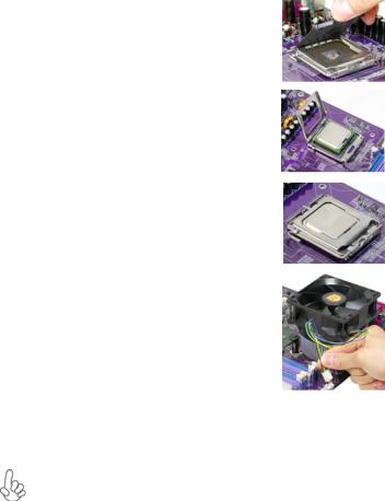
CPU Installation Procedure
The following illustration shows CPU installation components.
A.Unload the cap
·Use thumb & forefinger to hold the lifting tab of the cap.
·Lift the cap up and remove the cap completely from the socket.
B.Open the load plate
·Use thumb & forefinger to hold the
hook of the lever, pushing down and pulling aside unlock it.
·Lift up the lever.
·Use thumb to open the load plate. Be careful not to touch the contacts.
C.Install the CPU on the socket
·Orientate CPU package to the socket. Make sure you match triangle marker to pin 1 location.
D.Close the load plate
·Slightly push down the load plate onto the tongue side, and hook the lever.
·CPU is locked completely.
E.Apply thermal grease on top of the CPU.
F.Fasten the cooling fan supporting base onto the CPU socket on the motherboard.
G.Make sure the CPU fan is plugged to the
CPU fan connector. Please refer to the CPU cooling fan user’s manual for more detail installation procedure.
1.To achieve better airflow rates and heat dissipation, we suggest that you use a high quality fan with 3800 rpm at least. CPU fan and heatsink installation procedures may vary with the type of CPU fan/heatsink sup plied. The form and size of fan/heatsink may also vary.
2.DO NOT remove the CPU cap from the socket before installing a CPU.
Installing the Motherboard
15
Installing Memory Modules
This motherboard accomodates four memory modules. It can support two 240-pin 1.8V DDR2 667/533/400. The total memory capacity is 2GB.
DDR2 SDRAM memory module table
CPU FSB |
Memory module |
Memory Bus |
533/800MHz |
DDR2 400 |
200 MHz |
533/800/1066MHz |
DDR2 533 |
266MHz |
800/1066MHz |
DDR2 667 |
333MHz |
You must install at least one module in any of the two slots. Each module can be installed with 256 MB to 1 GB of memory; total memory capacity is 2 GB.
Do not remove any memory module from its antistatic packaging until you are ready to install it on the motherboard. Handle the modules only by their edges. Do not touch the components or metal parts. Always wear a grounding strap when you handle the modules.
Installation Procedure
Refer to the following to install the memory modules.
1This motherboard supports unbuffered DDR2 SDRAM .
2Push the latches on each side of the DIMM slot down.
3Align the memory module with the slot. The DIMM slots are keyed with notches and the DIMMs are keyed with cutouts so that they can only be installed correctly.
4Check that the cutouts on the DIMM module edge connector match the notches in the DIMM slot.
5Install the DIMM module into the slot and press it firmly down until it seats correctly. The slot latches are levered upwards and latch on to the edges of the DIMM.
6Install any remaining DIMM modules.
Installing the Motherboard
16
Table A: DDR2(memory module) QVL (Qualified Vendor List)
The following DDR2 400/533/667 memory modules have been tested and qualified for use with this motherboard.
|
|
|
|
|
Type |
Size |
Vendor |
Module Name |
|
|
|
|
|
|
DDR2 |
256MB |
Micron |
MT8HTF3264AG-40EB3 CL3 SS |
|
Hynix |
HYMP532U646-E3 AA |
|||
400 |
|
|||
|
Nanya |
NT256T64UH4A0F-5A CL3 |
||
|
|
|||
|
512MB |
Hynix |
HYMP564U648-E3 AA |
|
|
Nanya |
NT512T64U88A0F-5A CL3 |
||
|
|
|||
|
|
Samsung |
M378T3253FG0-CCC |
|
DDR2 |
256MB |
Elixir |
M2U25664TUH4A0F-37B CL4 |
|
Infineon |
HYS64T32000HU-3.7-A |
|||
533 |
|
|||
|
Kingston |
KVR533D2N4 |
||
|
|
|||
|
|
Samsung |
M378T3253FG0-CD5 CL4 |
|
|
512MB |
Elixir |
M2U51264TU88A0F-37B |
|
|
Kingston |
KVR533D2N4 |
||
|
|
|||
|
|
SAMSUNG |
M378T6553BGO-CD5 |
|
|
1GB |
Infineon |
HYS64T128020HU-3.7-A |
|
DDR2 |
256MB |
NANYA |
NT512T64U88A0BY-3C |
|
667 |
512MB |
ELPIDA |
EBE52UC8AAFV-DF-E |
|
|
|
|
|
Installing the Motherboard
17
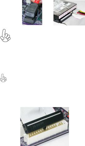
Installing a Hard Dish Drive/CD-ROM/SATA Hard Drive
This section describes how to install IDE devices such as a hard disk drive and a CD-ROM drive.
About IDE Devices
Your motherboard has one IDE channel interface. An IDE ribbon cable supporting two IDE devices is bundled with the motherboard.
You must orient the cable connector so that the pin1 (color) edge of the cable correspoinds to the pin 1 of the I/O port connector.
IDE1: IDE Connector
This motherboard supports four high data transfer SATA ports with each runs up to 150 MB/s. To get better system performance, we recommend users connect the CD-ROM to the IDE channel, and set up the hard dives on the SATA ports.
IDE devices enclose jumpers or switches used to set the IDE device as MASTER or SLAVE. Refer to the IDE device user’s manual. Installing two IDE devices on one cable, ensure that one device is set to MASTER and the other device is set to SLAVE. The documentation of your IDE device explains how to do this.
About SATA Connectors
Your motherboard features four SATA connectors supporting a total of four drives. SATA refers to Serial ATA (Advanced Technology Attachment) is the standard interface for the IDE hard drives which are currently used in most PCs. These connectors are well designed and will only fit in one orientation. Locate the SATA connectors on the motherboard and follow the illustration below to install the SATA hard drives.
Installing Serial ATA Hard Drives
To install the Serial ATA (SATA) hard drives, use the SATA cable that supports the Serial ATA protocol. This SATA cable comes with an SATA power cable. You can connect either end of the SATA cable to the SATA hard drive or the connector on the motherboard.
SATA cable (optional) |
SATA power cable (optional) |
Installing the Motherboard
18
Refer to the illustration below for proper installation:
1Attach either cable end to the connector on the motherboard.
2Attach the other cable end to the SATA hard drive.
3Attach the SATA power cable to the SATA hard drive and connect the other end to the power supply.
This motherboard does not support the “Hot-Plug” function.
Installing a Floppy Diskette Drive
The motherboard has a floppy diskette drive (FDD) interface and ships with a diskette drive ribbon cable that supports one or two floppy diskette drives. You can install a 5.25-inch drive and a 3.5-inch drive with various capacities. The floppy diskette drive cable has one type of connector for a 5.25-inch drive and another type of connector for a 3.5-inch drive.
You must orient the cable connector so that the pin 1 (color) edge of the cable corresponds to the pin 1 of the I/O port connector.
FDD: Floppy Disk Connector
This connector supports the provided floppy drive ribbon cable. After connecting the single end to the onboard floppy connector, connect the remaining plugs on the other end to the floppy drives correspondingly.
Installing the Motherboard
19
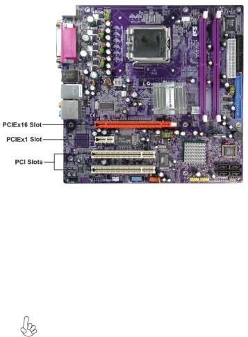
Installing Add-on Cards
The slots on this motherboard are designed to hold expansion cards and connect them to the system bus. Expansion slots are a means of adding or enhancing the motherboard’s features and capabilities. With these efficient facilities, you can increase the motherboard’s capabilities by adding hardware that performs tasks that are not part of the basic system.
PCIEX16 |
The one PCI Express x16 |
slot is fully compliant to the PCI Express Base |
slot |
Specification revision 1.0a |
as well |
PCIE1 (PCIE |
The two PCI Express x1 slots are fully compliant to the PCI Express Base |
|
x1) slot |
Specification revision 1.0a |
as well. |
PCI 1/2 |
This motherboard is equipped with two standard PCI slots. PCI stands for |
|
Slots |
Peripheral Component Interconnect and is a bus standard for expansion |
|
|
cards, which for the most part, is a supplement of the older ISA bus standard. |
|
|
The PCI slots on this board are PCI v2.3 compliant. |
|
Before installing an add-on card, check the documentation for the card carefully. If the card is not Plug and Play, you may have to manually configure the card before installation.
Installing the Motherboard
20
Follow these instructions to install an add-on card:
1Remove a blanking plate from the system case corresponding to the slot you are going to use.
2Install the edge connector of the add-on card into the expansion slot. Ensure that the edge connector is correctly seated in the slot.
3Secure the metal bracket of the card to the system case with a screw.
For some add-on cards, for example graphics adapters and network adapters, you have to install drivers and software before you can begin using the add-on card.
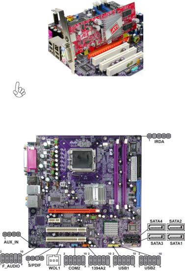
Connecting Optional Devices
Refer to the following for information on connecting the motherboard’s optional devices:
Installing the Motherboard
 Loading...