


Brief Introduction
Specifications
CPU |
• |
LGA1150 socket for 4th Generation Intel→ CoreTM Family/ |
||
|
|
Pentium/Celeron Processors |
||
|
Note: Please go to ECS website for the latest CPU support list. |
|||
|
|
|
||
Chipset |
• |
Intel→ H81 Chipset |
||
Memory |
• |
Dual-channel DDR3 memory architecture |
||
|
• |
2 x 240-pin DDR3 DIMM sockets support up to 16 GB |
||
|
• |
Supports DDR3 1600/1333 MHz DDR3 SDRAM |
||
|
|
|
|
|
Expansion |
• |
1 |
x PCI Express x16 Gen2 slot |
|
Slots* |
||||
• |
1 |
x Mini PCI Express x1 slot |
||
|
||||
|
Note: *PCIe SPEC will be changed with Intel latest CPU SPEC. |
|||
|
|
|
||
Storage |
• |
Supported by Intel→ H81 Express Chipset |
||
|
|
- 2 x Serial ATA 6Gb/s devices, 2 x Serial ATA 3Gb/s devices |
||
|
|
|
||
Audio |
• |
VIA VT1705CP |
||
|
|
- 6 Channel High Definiton Audio Codec |
||
|
|
- Compliant with HD audio specification |
||
|
|
|
||
LAN |
• |
Realtek RTL8111G Giga LAN |
||
|
|
- 10/100/1000 Fast Ethernet Controller |
||
|
|
- Wake-on-LAN and remote wake-up support |
||
|
|
|
||
Rear Panel I/O |
• |
1 x PS/2 keyboard and PS/2 mouse connectors |
||
|
• |
1 x DVI port* (or HDMI port) |
||
|
• |
1 x VGA port |
||
|
• |
4 x USB 2.0 ports* (or 2 x USB 3.0 ports and 2 x USB 2.0 ports) |
||
|
• |
1 x RJ45 LAN connector |
||
|
• |
1 x Audio port (1x Line in, 1x Line out, 1x Mic_in Rear) |
||
|
Note: *Please take the actual motherboard as standard. |
|||
|
|
|
||
Internal I/O |
• |
1 x 24-pin ATX Power Supply connector |
||
Connectors & |
• |
1 x 4-pin 12V Power connector |
||
Headers |
• |
1 x 4-pin CPU_FAN connector |
||
|
• |
1 x 4-pin SYS_FAN connector |
||
|
• |
2 |
x USB 2.0 headers support additional four USB 2.0 ports |
|
|
• |
1 |
x USB 3.0 header supports additional two USB 3.0 ports |
|
|
|
(Co-lay two USB 3.0 ports at the rear panel)* |
||
|
• |
2 |
x Serial SATA 6Gb/s connectors |
|
|
• |
2 |
x Serial SATA 3Gb/s connectors |
|
|
• |
1 x COM header |
||
|
• |
1 x Case open header |
||
|
• |
1 |
x Front Panel audio header |
|
|
• |
1 |
x Front Panel switch/LED header |
|
|
• |
1 |
x Speaker header |
|
|
• |
1 x ME_UNLOCK header |
||
|
• |
1 x CLR_CMOS jumper |
||
Note: *If there are dual USB 3.0 ports at the rear panel, the USB 3.0 header duo to Intel H81 chipset SPEC just supports two USB
3.0 ports. Please take the actual motherboard as standard.
H81H3-I USER MANUAL |
1 |
System BIOS |
• |
AMI BIOS with 64Mb SPI Flash ROM |
|
|
- Supports Plug and Play, STR(S3)/STD(S4) |
|
|
- Supports Hardware Monitor |
|
|
- Supports ACPI & DMI |
|
|
- Supports Audio, LAN, can be disabled in BIOS |
|
|
- F7 hot key for boot up devices option |
|
|
- Supports Pgup clear CMOS Hotkey (Has PS2 KB Model only) |
|
|
- Supports Dual Display (depends on display output) |
|
|
- Supports EZ BIOS (1024 x 768 resolution, GUI UEFI) |
|
|
- Supports Multi-language |
|
|
- Supports AC’97/HD Audio auto detect (default) |
|
|
|
AP/Bundled |
• |
ECS Exclusive AP: Supports eBLU*1/eDLU/eSF*1 |
Software |
• |
3rd Party Bundled software: Cyberlink Media Suite*2/Norton |
Support |
|
Anti Virus*2/Muzee*2 |
|
Note: *1Microsoft .NET Framework 3.5 is required. |
|
|
|
*2Free bundle software including ECS DVD: Cyberlink Media |
|
|
Suite/Norton Anti Virus/Muzee |
|
|
|
Form Factor |
• |
Mini-ITX 170mm x 170mm |
|
|
|
Specifications are subject to change without notice.
QR Code for the complete manual download on ECS website: http://www.ecs.com.tw
2 |
H81H3-I USER MANUAL |
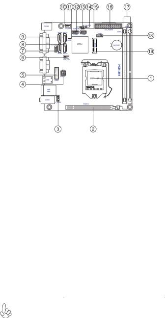
Motherboard Components
Table of Motherboard Components
LABEL |
COMPONENTS |
1. CPU Socket |
LGA1150 socket for Intel® 4th Generation |
|
CoreTM Family/Pentium/Celeron processors |
2. PCIEX16 |
PCI Express slot for graphics interface |
3. F_AUDIO |
Front panel audio header |
4. ATX12V |
4-pin +12V power connector |
5. USB3F* |
Front panel USB 3.0 header |
6. SYS_FAN |
3-pin system cooling fan connector |
7. F_PANEL |
Front panel switch/LED header |
8. SATA1~2 |
Serial ATA 6Gb/s connectors |
9. SATA3~4 |
Serial ATA 3Gb/s connectors |
10. CPU_FAN |
4-pin CPU cooling fan connector |
11. CASE |
CASE open header |
12. F_USB1~2 |
Front panel USB 2.0 headers |
13. SPK |
Speaker header |
14. ME_UNLOCK |
ME unlock header-for factory use only |
15. CLR_CMOS |
Clear CMOS jumper |
16. ATX_POWER |
Standard 24-pin ATX power connector |
17. DDR3_1~2 |
240-pin DDR3 Module slots |
18. COM1 |
Onboard serial port header |
19. MPCIE |
Mini PCI Express x1 slot |
*If there are dual USB 3.0 ports at the rear panel, the USB 3.0 header duo to Intel H81 chipset SPEC just supports two USB 3.0 ports. Please take the
actual motherboard as standard.
H81H3-I USER MANUAL |
3 |
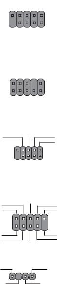
,ĞĂĚĞƌ WŝŶ ĞĮŶŝƟŽŶ ĂŶĚ :ƵŵƉĞƌ ^ĞƫŶŐƐ
F_PANEL
Reset Switch (+) |
|
Reset Switch (-) |
|
Hard disk LED (-) |
||||||||
|
|
|
|
|
|
|
|
|
|
|
||
Reserved |
|
|
|
|
|
|
|
|
|
|
|
Hard disk LED (+) |
|
|
|
|
|
|
|
|
|
1 |
|
||
KEY |
|
|
|
|
|
|
|
|
|
|
MSG LED (+) |
|
|
|
|
|
|
|
|
|
|
|
|
||
|
|
|
|
|
|
|
|
|
|
|
||
|
|
|
|
|
|
|
|
|
|
|
||
|
|
|
|
|
|
|
|
|
|
|
||
|
|
|
|
|
|
|
|
|
|
|
||
|
|
|
|
|
|
|
|
|
|
|
||
Power Switch (-) |
|
|
|
|
|
|
|
|
|
|
|
MSG LED (-) |
|
|
|
|
|
|
|
|
|
|
|
||
|
Power Switch (+) |
|
||||||||||
|
|
|
|
|||||||||
F_AUDIO |
|
|
|
|
|
|
|
|
|
|
|
|
PRESENCE# |
|
|
SENSE1_ |
RETURN |
Key |
|||||||
|
|
|
|
|
|
|
|
|
|
|
||
AUD_GND |
|
|
|
|
|
|
|
|
|
|
|
SENSE2_RETURN |
1 |
|
|
|
|
|
|
|
|
|
|
||
PORT 1L |
|
|
|
|
|
|
|
|
|
|
PORT 2L |
|
|
|
|
|
|
|
|
|
|
|
|||
|
|
|
|
|
|
|
|
|
|
|||
|
|
|
|
|
|
|
|
|
|
|||
|
|
|
|
|
|
|
|
|
|
|||
|
|
|
|
|
|
|
|
|
|
|||
|
|
|
|
|
|
|
|
|
|
|
||
PORT 1R |
|
|
|
|
|
|
|
|
|
|
|
SENSE_SEND |
|
|
PORT 2R |
|
|||||||||
|
|
|
|
|
||||||||
COM1
Ground
Request to Send Ring Indicator 
1
Serial Output
Data Carrier Detect
Key |
|
|
|
|
|
|
|
Serial Input |
|
|
|
|
|
|
|||
Clear to Send |
|
|
|
|
|
|
|
Data Terminal Ready |
|
|
|
|
|
|
|||
Data Set Ready |
|
|||||||
|
|
|
||||||
F_USB1~2
USB Port B (-) |
|
USB Port B (+) |
|
|
Ground |
||
Power +5V |
|
NC |
|
|
1 |
9 |
|
Power +5V |
KEY |
||
|
|||
USB Port A (-) |
|
Ground |
|
|
|
USB Port A (+) |
|
SPK |
|
|
|
VCC |
|
Signal |
|
|
1 |
|
|
Key |
|
GND |
4 |
H81H3-I USER MANUAL |
|
USB3F*
Not Connected |
|
|
|
|
|
|
|
USB3 ICC Port2 D+ |
|
|
|
|
|
|
|
||
USB3 ICC Port1 D+ |
|
|
|
|
|
|
|
USB3 ICC Port2 D- |
|
|
|
|
|
|
|
||
USB3 ICC Port1 D- |
|
|
|
|
|
|
|
Ground |
|
|
|
|
|
|
|
||
Ground |
|
|
|
|
|
|
|
USB3 ICC Port2 SuperSpeed Tx+ |
|
|
|
|
|
|
|
||
USB3 ICC Port1 SuperSpeed Tx+ |
|
|
|
|
|
|
|
USB3 ICC Port2 SuperSpeed Tx- |
|
|
|
|
|
|
|
||
USB3 ICC Port1 SuperSpeed Tx- |
|
|
|
|
|
|
|
Ground |
|
|
|
|
|
|
|
||
Ground |
|
|
|
|
|
|
|
USB3 ICC Port2 SuperSpeed Rx+ |
|
|
|
|
|
|
|
||
USB3 ICC Port1 SuperSpeed Rx+ |
|
|
|
|
|
|
|
USB3 ICC Port2 SuperSpeed Rx- |
|
|
|
|
|
|
|
||
USB3 ICC Port1 SuperSpeed Rx- |
|
|
|
|
|
|
|
Front Panel USB Power |
|
|
|
|
|
|
|
||
Front Panel USB Power |
|
|
|
|
|
|
|
|
|
|
|
|
|
|
|
|
|
1 |
|
|
|
|
|
|||
|
|
|
|
|
|
|||
*If there are dual USB 3.0 ports at the rear panel, the USB 3.0 header duo to Intel H81 chipset SPEC just supports two USB 3.0 ports. Please take the actual motherboard as standard.
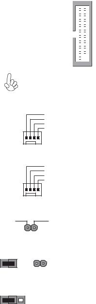
CPU_FAN
System Ground
Power +12V
Sensor
PWM
1
SYS_FAN
|
|
|
System Ground |
|
|
|
Power +12V |
|
|
|
Sensor |
|
|
|
PWM |
|
|
1 |
|
CASE |
|
|
|
Intruder |
|
GND |
|
|
|
1 |
|
ME_UNLOCK |
|
||
UNLOCK |
|
LOCK |
|
CLR_CMOS Jumper |
|||
|
|
|
1-2: NORMAL |
1 |
2 |
3 |
2-3: CLEAR CMOS |
|
|||
CLR_CMOS |
Before clearing the CMOS, make sure to turn off the system. |
|
H81H3-I USER MANUAL
5
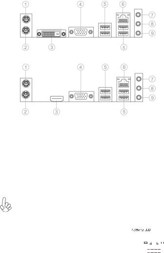
I/O Ports
Or
1. PS/2 Mouse(green)
Use the upper PS/2 port to connect a PS/2 mouse.
2. PS/2 Keyboard(purple)
Use the lower PS/2 port to connect a PS/2 keyboard.
3. DVI Port(Co-lay HDMI port)
Connect the DVI/HDMI port to the monitor.
4. VGA Port
Connect your monitor to the VGA port.
5. USB 2.0 Ports(or two USB 3.0 ports)*
Use the USB 2.0/USB 3.0 ports to connect USB 2.0/USB 3.0 devices.
*Please take the actual motherboard as standard.
6. LAN Port
Connect an RJ-45 jack to the LAN port to connect your computer to the Network.
|
|
|
|
|
|
|
|
|
|
|
|
Link LED |
|||||
LAN LED |
Status |
Description |
|||||||||||||||
|
|
|
|
|
|
|
|
|
|
|
|
|
|
||||
|
|
|
|
|
|
|
|
|
|
|
|
|
|
|
|
|
|
Activity LED |
OFF |
No data |
|
|
|
|
|
|
|
|
|
|
|
|
|
|
|
|
Orange blinking |
Active |
|
|
|
|
|
|
|
|
|
|
|
|
|
|
|
Link LED |
OFF |
No link |
|
|
|
|
|
|
|
|
|
|
|
|
|
|
|
|
|
|
|
|
|
|
|
|
|
|
|
|
|
||||
Green |
Link |
|
|
LAN Port |
|||||||||||||
|
|
|
|||||||||||||||
7. Line-in(blue)
It can be connected to an external CD/DVD player, Tape player or other audio devices for audio input.
8. Line-out(lime)
It is used to connect to speakers or headphones.
9. Microphone(pink)
It is used to connect to a microphone.
6 |
H81H3-I USER MANUAL |
Hardware Installation Guide
Installation Steps
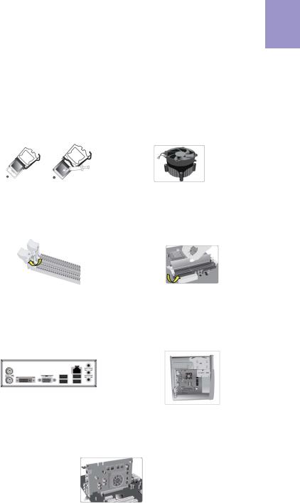
Step 1. Installation of the CPU and CPU Cooler:
1-1. Pull up the lever away from the |
1-2. Rotate and press down the fastener |
socket. Align the CPU cut edge with the |
of CPU fan to the motherboard through |
indented edge of the CPU socket. |
holes to install CPU fan into place. |
Gently place the CPU into correct |
|
position. Apply an even layer of thermal |
|
grease on the surface of CPU. |
|
English
Step 2. Installation of Memory Modules:
2-1. Unfasten the latches on each side of the DIMM slots.
2-2. Firmly press the DIMM down until it seats correctly. Make sure the slot latches are levered upwards and latch on the edge of the DIMM.
Step 3. Installation of Motherboard:
3-1. Replace the back I/O plate of the case with the I/O shield provided in motherboard’s package.
3-2. Place the motherboard within the case by positioning it into the I/O plate. Secure the motherboard to the case with screws.
Step 4. Installation of an Expansion card:
Remove the metal located on the slot and then insert the expansion card into the slot. Press the card firmly to make sure it is fully inserted into its slot. And then return the screw back to its position.
7
English
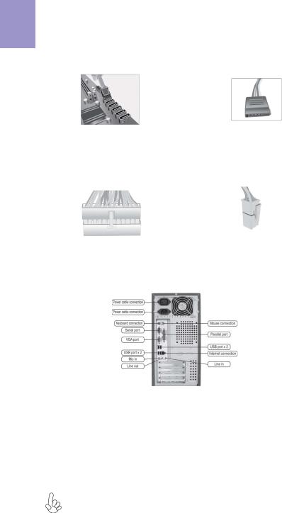
Step 5. Connecting Cables and Power Connectors:
a. Connect the SATA hard drive to its |
b. Connect SATA power connector to the |
SATA cable |
SATA device |
c. Connect 24-pin power cable
Please note that when installing 24-pin power cable, the latches of power cable and the ATX connector match perfectly.
d. Connect 4-pin power cable
The ATX_12V 4-Pin power connector is used to provide power to the CPU. When installing 4-pin power cable, the latch of power cable matches the ATX_12V connector perfectly.
Step 6: Connecting ports on the case:
Once the steps above have been completed, please connect the peripherals such as the keyboard, mouse, monitor, etc. Then, connect the power and turn on the system. Please install all the required software.
Using BIOS
The BIOS (Basic Input and Output System) Setup Utility displays the system’s configuration status and provides you options to set system parameters. When you power on the system, BIOS enters the Power-On Self Test (POST) routines, please press <DEL> or F2 to enter setup. When powering on for the first time, the POST screen may show a “CMOS Settings Wrong” message. Please enter BIOS and choose “Load Default Settings” to reset the default CMOS values. (Changes to system hardware such as different CPU, memories, etc. may also trigger this message.)
The sequence of installation may differ depending on the type of case and devices used.
8

Manual de Instalação de Hardware
Etapas para instalação
Passo 1. Instalação da CPU e da CPU Refrigeração (Cooler):
1-1. Puxe a alavanca para fora do soquete. Alinhe o lado da CPU com o lado correto do soquete do processador. Delicadamente, coloque o processador na posição correta. Aplique uma camada 
 da CPU.
1-2. Gire e pressione para baixo a alavanca de fecho da ventoinha da CPU
Português
Passo 2. Instalação de módulos de memória:
2-1. Solte as travas em cada lado dos slots DIMM.
2-2. Pressione Įrmemente o módulo DIMM para baixo até que Įque corretamente encaixado. VeriĮque se as travas do slot estão correctamente posicionadas e travam a extremidade do DIMM.
Passo 3. Instalação da Placa-mãe:
3-1. Mude a placa I/O que se encontra no gabinete pela placa de blindagem fornecida no pacote da placa-mãe.
3-2. Coloque a placa-mãe dentro do gabinete, posicionando-a no encaixe do I/O. Fixe a placa-mãe ao gabinte com parafusos.
Passo 4. Instalação de uma placa de expansão:
Em seguida coloque o parafuso para sua posição de origem.
9
 Loading...