

Page 1

ISTRUZIONI PER L'USO
IT
INSTRUCTIONS FOR USE
BEDIENUNGSANLEITUNG
NOTICE D'UTILISATION
INSTRUCCIONES PARA EL USO
GEBRUIKSAANWIJZING
EN
DE
FR
ES
NL
Page 2

ITALIANO
• INTRODUZIONE 4
• NOME E LISTA DEI COMPONENTI 4
• MONTAGGIO 4
• UTILIZZO 5
• CURA E MANUTENZIONE 5
• ATTENZIONI 6
• ACCESSORI DI COMPLETAMENTO (solo su richiesta) 6
ENGLISH
• INTRODUCTION 7
•COMPONENTS NAMES AND LIST 7
• ASSEMBLY 7
• USE 8
• MAINTENANCE 8
• WARNING 8
• OTHER ACCESSORIES (only on demand) 8
DEUTSCH
• EINLEITUNG 10
• BEZEICHNUNG UND LISTE DER KOMPONENTEN 10
• MONTAGE 10
• BENUTZUNG 11
• PFLEGE UND WARTUNG 12
•
• ERGÄNZENDES ZUBEHÖR (nur auf Anfrage) 12
ACHTUNG 12
Page 3

FRANÇAIS ESPAÑOL DUTCH
• INTRODUCTION 13
• NOM ET LISTE DES ELEMENTS 13
• ASSEMBLAGE 13
• UTILISATION 14
• SOIN ET ENTRETIEN 14
• ATTENTION 15
• ACCESSOIRES POUR COMPLETER (uniquement sur demande) 15
• INTRODUCCIÓN 16
• NOMBRE Y LISTA DE LOS COMPONENTES 16
• MONTAJE 16
• USO 17
• CUIDADOS Y MANTENIMIENTO 18
• ADVERTENCIAS 18
• ACCESORIOS DE COMPLEMENTO (solo a pedido) 18
• INLEIDING 19
• BENAMING EN LIJST VAN DE ONDERDELEN 19
• MONTAGE 19
• GEBRUIK 20
• VERZORGING EN ONDERHOUD 21
• LET OP 21
• AANVULLENDE ACCESSOIRES (alleen op aanvraag) 21
Page 4

IT
ITALIANO
INTRODUZIONE
Grazie per aver scelto di acquistare il nostro
Sanremo Race Lock, un supporto per il trasporto di biciclette da montare su barre
portatutto a sezione quadra, rettangolare,
tonda ed ellittica (larghezza max 80 mm altezza max 50 mm).
Sanremo Race Lock è composto da un supporto anteriore + supporto posteriore, compatibili con ogni genere di bicicletta, sia da
corsa sia da MTB, con freni V-Brake che a
disco, con forcelle standard, ammortizzate e
in carbonio.
Un'ampia regolazione sul passo fino a 610
mm permette di trasportare qualsiasi taglia
di bicicletta, anche su vetture con passo
delle barre molto stretto.
Tali caratteristiche lo rendono il più versatile della categoria.
bloccare il supporto posteriore (Rif. B) con
il supporto inferiore (Rif. C), interponendo
fra i due componenti la barra portatutto
(Fig. 4, 5 e 6). Serrare i bulloni fino a completo bloccaggio.
Supporto anteriore:
• Prendere il supporto anteriore (Rif. A) (Fig.
7) e tramite la chiave antifurto sbloccare la
maniglia (Fig. 8 e Fig. 9).
ATTENZIONE
• Per facilitare le operazioni di utilizzo, prestare attenzione al senso della maniglia.
Esempio: lato guidatore - maniglia esterna
(Fig. 10 e Fig. 11).
Esempio: lato passeggero anteriore - maniglia esterna ( Fig. 12 e Fig. 13).
NOME E LISTA DEI COMPONENTI
• N°1 Supporto Anteriore (Rif. A);
• N°1 Supporto Posteriore (Rif. B);
• N°2 Supporto Inferiore (Rif. C);
• N°1 Fissaggio Rapido (Rif. D);
• N°1 Fascetta (Rif. E);
• N°4 Vite M6 (Rif. F);
• N°4 Dado M6 (Rif. G);
• N°2 Rosette M6 (Rif. H);
• N°1 Chiave Esagonale;
• N°2 Chiave Antifurto.
MONTAGGIO
Supporto posteriore:
• È possibile montare il fissaggio rapido (Rif.
D) da destra o da sinistra a seconda delle
esigenze (Fig. 2 e Fig. 3).
• Con la chiave esagonale in dotazione,
• Se la maniglia non risultasse come nelle
figure sopraindicate, dovrete solamente
girare la maniglia antifurto verso il lato
opposto da quella prestabilita.
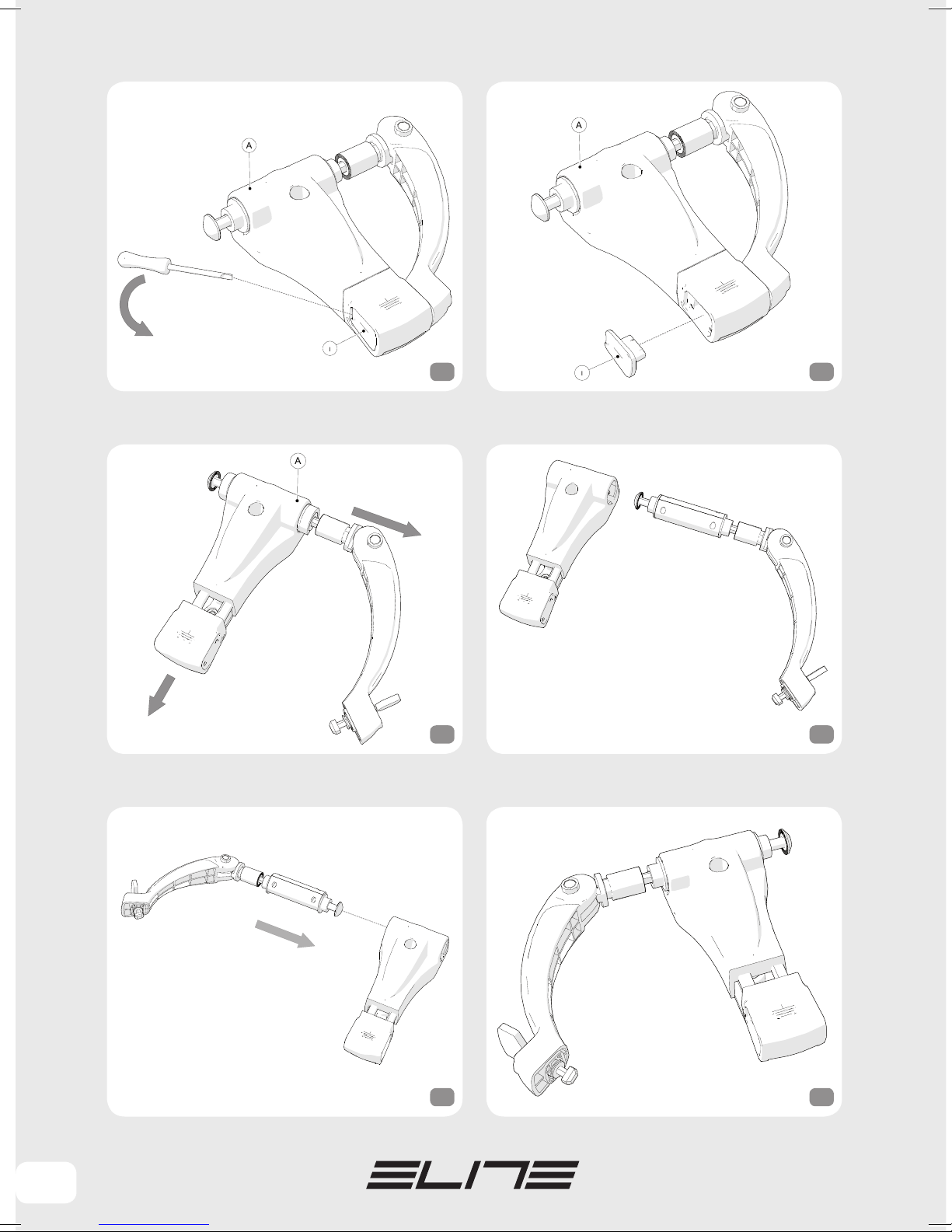
• Aiutarsi facendo leva con un cacciavite a
taglio per rimuovere il coperchio antifurto
(Rif. I) dal supporto anteriore (Rif. A) (Fig. 14
e Fig. 15) ed aprire la leva (Fig. 8 e Fig. 9).
• Portare la slitta anteriore (Rif. L) nella sua
massima posizione (Fig. 16) , sfilare il blocco maniglia (Fig. 17 ) ed inserirla nella parte
opposta (Fig. 18 e Fig. 19), per far si che
rispetti la corretta posizione tra lato passeggero anteriore - maniglia esterna (Fig.
12 e Fig. 13).
ATTENZIONE!
• Il perno maniglia deve entrare nella
rispettiva sede intagliata sull'alluminio del
4
Page 5

IT
supporto anteriore (Rif. A) (Fig. 20 e Fig.21).
• Il perno maniglia deve entrare completamente all'interno del supporto slitta (Rif. A) (Fig. 22).
• Riporre il coperchio antifurto (Rif. I) nel
supporto anteriore (Rif. A) esercitando una
leggera pressione, in modo che si agganci
correttamente.
Eseguire due scatti alla slitta, in modo che
ritorni in posizione iniziale (Fig. 23).
• Deciso il lato maniglia, dovrete andare
inserire la viteria per il fissaggio dei supporti alla barra.
• Far scorrere in avanti la slitta del supporto
anteriore (Rif. A) di uno scatto (Fig. 24), in
modo da inserire le viti (Rif. F) e le rosette (Rif.
H) all'interno delle rispettive sedi (Fig. 25).
• Con la chiave esagonale in dotazione, bloccare il supporto anteriore (Rif. A) con il
supporto inferiore (Rif. C), interponendo fra
i due componenti la barra portatutto (Fig.
26, 27 e 28). Serrare i bulloni fino a completo bloccaggio.
• Chiudere la slitta del supporto anteriore
(Rif. A) (Fig. 29 e Fig.30) , bloccare la maniglia in sede (Fig. 7) e tramite la chiave antifurto bloccare la maniglia (Fig. 31).
UTILIZZO
• Aprire il fissaggio rapido del supporto posteriore (Rif. B) (Fig. 32).
• Togliere dalla bici la ruota anteriore ed
appoggiare la ruota posteriore sopra la culla
del supporto posteriore (Rif. B) (Fig. 33 e Fig.
34).
• Con la leva completamente aperta inserire la
forcella della bici sul perno del supporto anteriore (Rif. A) prestando attenzione che le forcelle vadano in appoggio senza impedimenti e con
la massima libertà (Fig. 35).
• Se ciò non avvenisse (Fig. 36) , ruotare la
bussola di regolazione (Rif. M) (presente sul
supporto anteriore (Rif. A) ) nel senso della
freccia (Fig. 37) fino a che le estremità della
forcella possano entrare liberamente (Fig. 38).
ATTENZIONE: per facilitare l'inserimento
della forcella della bici sul perno, tirare con
una mano la maniglia fino a che le estremità
della forcella possa entrare liberamente
(Fig. 39).
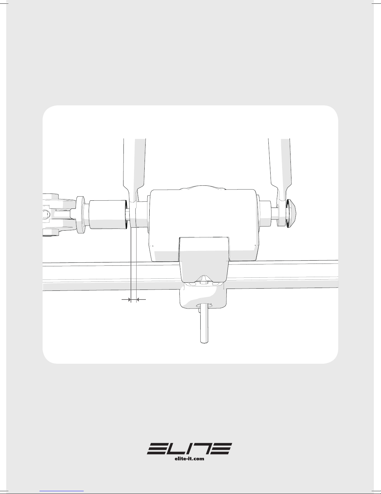
• Posizionare la leva maniglia a 0-20° (Fig.
40), se la superficie del supporto anteriore e
la forcella sono già in compressione, ruotare
la bussola di regolazione (Rif. M) (Fig. 37) fino
ad arrivare a 0-20° senza compressione.
• Se posizionando la leva maniglia ed il
gioco tra la superficie del supporto anteriore
e la forcella risulta maggiore a 0-20° (Fig.
40), ruotare la bussola di regolazione (Rif. M)
(Fig. 41) fino ad arrivare a 0-20° gradi senza
compressione.
• Chiudere la leva facendo attenzione del
corretto posizionamento dell'estremità del
perno sulla maniglia (Fig. 42 e Fig. 43) e
ruotare la chiave antifurto (Fig. 31).
• Ricordarsi di togliere sempre la chiave prima
dell'utilizzo (si consiglia di riporre la seconda
chiave in dotazione separatamente dalla
prima in modo di avere la possibilità di duplicazione della stessa in caso di smarrimento).
• Fissare la ruota posteriore della bici alla
culla del supporto posteriore con la fascetta
in dotazione (Rif. E) facendola scorrere nelle
apposite fessure.
Chiudere il fissaggio rapido (Fig. 44).
CURA E MANUTENZIONE
• Pulire sempre il Sanremo Race Lock dopo l'uso.
ITALIANO
5
Page 6

IT
• Non usare solventi o detergenti aggressivi.
ITALIANO
• Non utilizzare prodotti abrasivi.
• Togliere sempre la chiave prima di avviare
la corsa (Fig. 45).
• Controllare il corretto fissaggio della bicicletta dopo i primi Km e successivamente
eseguire periodici controlli durante la corsa
(Fig. 50).
• Verificare che le parti della bici (cavi e
componenti vari) non siano forzati in modo
eccessivo durante il montaggio (Fig. 55-5657-58).
• Adattatore per perno passante (Rif. N);
• Blocchetto chiave (Rif. O);
• Chiave Antifurto.
ATTENZIONI
ACCESSORI DI COMPLETAMENTO
(solo su richiesta)
all'interno del supporto anteriore (Rif. A)
(Fig. 64) facendo attenzione che la parte con
l'intaglio sia rivolta verso il basso (Fig.
65-66-67).
• Per il fissaggio alla barra portatutto seguire il capitolo "MONTAGGIO".
• Portare la slitta nella posizione iniziale ed
inserire il blocchetto chiave (Rif. O) al supporto anteriore (Fig. 68).
ATTENZIONE: inserire i pioli del blocchetto
all'interno delle rispettive sedi (Fig. 69).
• Tramite la chiave antifurto chiudere il
blocchetto maniglia (Fig. 70).
• Togliere dalla bici la ruota anteriore, accostare e trattenere con una mano la forcella
della bici all’adattatore per perno passante
(Rif. N), inserire ed avvitare il perno passante (Fig.71).
• Bloccare il perno passante alla forcella
(Fig. 72).
• Per il fissaggio della ruota posteriore fare
riferimento al capitolo "UTILIZZO".
• Per bici con perno passante Ø 20 mm, Elite
mette a disposizione un perno d'adattamento, un blocchetto chiave e la chiave antifurto
(Fig. 62).
• Per bici con perno passante Ø 15 mm, Elite
mette a disposizione un perno d'adattamento, un blocchetto chiave e la chiave antifurto
(Fig. 63).
UTILIZZO
• Tenendo in posizione di massima apertura
la slitta anteriore, sfilare il blocco maniglia
(Fig. 16 e Fig. 17), inserire il perno (Rif. N)
6
Page 7

EN
INTRODUCTION
Thank you for choosing our Sanremo Race
Lock, a bike carrier that can be mounted on
square, rectangular, round and elliptical bar
racks (maximum width 80 mm – maximum
height 50 mm).
Sanremo Race Lock has a front support + rear
support that’s compatible with any kind of bike,
both race and MTB, V-Brake or Disc brakes with
standard, shock absorbing or carbon forks.
A wide distance adjustment up to 610 mm
allows to carry bikes of any size, also on cars
with very tight bar distance.
These features make it the most versatile carrier of its kind.
COMPONENTS NAMES AND LIST
• N°1 Front Support (Ref. A);
• N°1 Rear Support (Ref. B);
• N°2 Lower Support (Ref. C);
• N°1 Quick Release (Ref. D);
• N°1 Strap (Ref. E);
• N°4 M6 Screws (Ref. F);
• N°4 M6 Bolts (Ref. G);
• N°2 M6 Washers (Ref. H);
• N°1 Hex key;
• N°2 Anti-theft key.
ASSEMBLY
pletely locked.
Front support:
• Use the Anti-theft key to unlock the handle (pics
8 and 9) with the Front Support (Ref. A) (pic 7).
WARNING
• Mind the direction of the handle in order to
facilitate set up.
Example: driver’s side – external handle
(pics 10 and 11).
Example: front passenger side – external
handle ( Pics 12 and 13).
• If the handle does not appear as seen in
the previous pictures, just turn the antitheft handle towards the opposite side from
the pre-set one.
• Get some leverage with a screwdriver to
remove the anti-theft cover (Ref. I) from the
front support (Ref. A) (pics 14 and 15) and
open the lever (pics 8 and 9).
• Bring the front slide (Ref. L) to its maximum extension (pic 16), slip the handle
block (pic 17) and insert it in the opposite
side (pics 18 and 19) in order to set the correct position between front passenger side
and external handle (pics 12 and 13).
ENGLISH
Rear support:
• It is possible to install the fast fixing
mechanism (Ref. D) from the left or the
right based on one’s needs (pics 2 and 3).
• Lock together the Rear Support (Ref. B)
with the Lower Support (Ref. C) by using
the supplied Hex key, interjecting the bar
rack with the two components (pics 4, 5
and 6). Tighten the bolts until they’re com-
WARNING!
• The handle pin has to fit in its seating carved in aluminium on the front support (Ref.
A) (pics 20 and 21).
• The handle pin has to completely fit in the
slide support (Ref. A) (pic 22).
• Put back the anti-theft cover (Ref. I) on the
front support (Ref. A) by slightly pressing on
it, so that it hooks on correctly.
7
Page 8

EN
The slide shall then clock twice and go back
to its first position. (pic 23).
• Once you selected the handle side, insert
the screws to clamp the supports on the bar.
• Slip forward the front support slide (Ref. A)
by one click (pic 24), so that you can insert
the screws (Ref. F) and the washers (Ref. H)
ENGLISH
in their own seatings (pic 25).
• Lock the front support (Ref. A) and the
lower support (Ref. C) with the supplied Hex
key, by interjecting them with the bar rack
(pics 26, 27 and 28). Tighten bolts until
they’re completely locked.
• Closet the front support slide (Ref. A) (pics
29 and 30) , lock the handle in its seating (pic
7) with the anti-theft key (pic 31).
USE
fork are already touching.
• If the distance between surface of the front
support and fork is more than 0-20° (pic 40)
while positioning the handle lever, turn the
adjusting bush (Ref. M) (pic 41) until it gets
to 0-20° without coming into contact.
• Close the lever and place correctly the
edge of the pin on the handle (pic 42 and 43)
and turn the anti-theft key (pic 31).
• Remember to always remove the key before use (we suggest to store separately the
spare key we supply in order to have it ready
in case you misplace the first one).
• Position the rear wheel of the bike on the
cradle of the rear support with the supplied strap
(Ref. E) by making it slide into its proper slots.
Close the fast fixing mechanism (pic 44).
• Release the fast fixing mechanism of the
rear support (Ref. B) (pic 32).
• Remove the front wheel of the bike and
place the rear wheel above the cradle of the
rear support (Ref. B) (pics 33 and 34).
• Open the lever completely and place the
fork of the bike on the front support pin (Ref.
A) – the fork has to lean freely and without
obstructions (pic 35).
• If that doesn’t happen (pic 36), turn the
adjusting bush (Ref. M) on the front support
(Ref. A) facing the direction of the arrow (pic
37) until both edges of the fork can be inserted without obstructions (pic 38).
ATTENTION: to facilitate insertion of the bicycle
fork on the pin, pull the handle with one hand until
the ends of the fork can enter freely (Fig. 39).
• Place the handle lever at 0-20° (pic 40) and
turn the adjusting bush (Ref. M) (pic 37) until
it gets to 0-20° without coming into contact
if the surface of the front support and the
MAINTENANCE
• Always clean the Sanremo Race Lock after use.
• Do not use solvents or strong detergents.
• Do not use products with abrasive substances.
WARNING
• Always remove the key before the race.
• After the first few miles check the correct
positioning of the bike and do so periodically
to time while travelling (pic 50).
• Check that bike parts (cables and other
components) are not excessively constrained when assembling (pics 55-56-57-58).
OTHER ACCESSORIES
(only on demand)
• Pivot Pin adapter (Rif. N);
8
Page 9

• Key Block (Rif. O);
• Anti-theft key.
• For bikes with Ø20 mm pivot pin, ELITE
supplies an adjusting pin, a key block and
the anti-theft key (pic 62).
• For bikes with Ø15 mm pivot pin, ELITE
supplies an adjusting pin, a key block and
the anti-theft key (pic 63).
USE
• Slide the handle block (pics 16 and 17) by
keeping the front slide as open as possible,
and slide the pin (Ref. N) inside the front
support (Ref. A) (pic 64) making sure that the
carved part is facing down (pics 65, 66 and
67).
• See chapter "ASSEMBLY" for installation
on bar rack.
• Move the slide on the initial position and
insert the key block (Ref. O) on the front
support (pic 68).
EN
ENGLISH
ATTENTION: insert the pins of the block
inside their proper housings (pics 69).
• Close the handle block with the anti-theft
key (pic 70).
• Remove the front wheel from the bicycle,
hold the bicycle fork with one hand and
bring it near the adapter for through pin
(Ref. N), insert and screw the through pin
(Fig.71).
• Secure the through pin to the fork (Fig. 72).
• See chapter "USE" for rear wheel fastening.
9
Page 10

DE
Besten Dank für den Kauf unseres Sanremo
Race Lock, eines Fahrradträgers, der auf
Dachständer mit Stangen von quadratischem,
rechteckigem, rundem und elliptischem
Querschnitt (Breite max. 80 mm – Höhe max. 50
mm) montiert werden kann.
Sanremo Race Lock besteht aus einer vorderen
+ einer hinteren Halterung, die mit jeder Art von
Fahrrad – sowohl Rennrad als auch MTB, sowohl
mit V-Bremse als auch mit Scheibenbremse,
sowohl mit Standard- als auch mit Feder- und
mit Carbon-Gabel – kompatibel ist.
DEUTSCH
Ein großzügig bemessener Regelbereich des
Mittenabstands bis zu 610 mm gestattet es, auch
auf Fahrzeugen mit sehr engem Mittenabstand
zwischen den Stangen jede Fahrradgröße zu
transportieren.
Diese Eigenschaften lassen Sanremo Race Lock
zum vielseitigsten seiner Kategorie werden.
EINLEITUNG
montiert werden (Abb. 2 und Abb. 3).
Mit Hilfe des in der Lieferung enthaltenen
Sechskantschlüssels die hintere Halterung
(Bez. B) mit der unteren Halterung (Bez. C)
verbinden, wobei die Stange des Dachständers
zwischen die beiden Komponenten eingefügt
wird (Abb. 4, 5 und 6). Die Schraubbolzen bis
zur vollständigen Sperre anziehen.
Vordere Halterung:
Die vordere Halterung (Bez. A) (Abb. 7) greifen und
den Griff mittels des Diebstahlsicherungsschlüssels
freigeben (Abb. 8 und Abb. 9).
ACHTUNG
• Zur Erleichterung der Gebrauchsvorgänge
auf die Ausrichtung des Griffs achten.
Beispiel: Fahrerseite – Griff Aussen (Abb. 10
und Abb. 11).
Beispiel: Vordere Beifahrerseite –Griff
Aussen (Abb. 12 und Abb. 13).
BEZEICHNUNG UND LISTE DER
KOMPONENTEN
• 1 St. vordere Halterung (Bez. A);
• 1 St. hintere Halterung (Bez. B);
• 2 St. untere Halterung (Bez. C);
• 1 St. Schnellbefestigung (Bez. D);
• 1 St. Band (Bez. E);
• 4 St. Schrauben M6 (Bez. F);
• 4 St. Muttern M6 (Bez. G);
• 2 St. Unterlegscheiben M6 (Bez. H);
• 1 St. Sechskantschlüssel;
• 2 St. Diebstahlsicherungsschlüssel.
MONTAGE
Hintere Halterung:
Die Schnellbefestigung (Bez. D) kann je nach
den Anforderungen von rechts oder links
• Falls sich der Griff als nicht wie in den obigen
Abbildungen dargestellt erweist, muss der
Diebstahlsicherungsgriff lediglich entgegengesetzt zur vorher festgelegten Seite gedreht
werden.
• Einen als Hebel dienenden
Schlitzschraubenzieher zu Hilfe nehmen, um
die Diebstahlsicherungsabdeckung (Bez. I) von
der vorderen Halterung (Bez. A) zu entfernen
(Abb. 14 und Abb. 15), und den Hebel öffnen
(Abb. 8 und Abb. 9).
• Die vordere Gleitschiene (Bez. L) in ihre maximale Position bringen (Abb. 16), den Griffblock
herausziehen (Abb. 17) und auf der entgegengesetzten Seite einführen (Abb. 18 und Abb.
19), damit die korrekte Position zwischen vorderer Beifahrerseite –Griff außen eingehalten
wird (Abb. 12 und Abb. 13).
10
Page 11

DE
ACHTUNG!
• Der Griffzapfen muss in den entsprechenden
im Aluminium der vorderen Halterung (Bez. A)
eingekerbten Sitz eintreten (Abb. 20 und Abb.21).
• Der Griffzapfen muss vollständig ins Innere
der Gleitschienenhalterung (Bez. A) eintreten
(Abb. 22).
• Die Diebstahlsicherungsabdeckung (Bez. I)
wieder in der vorderen Halterung (Bez. A)
anbringen, wobei ein leichter Druck ausgeübt
wird, damit sie korrekt einkuppelt.
Zwei Ruckbewegungen an der Gleitschiene vor
nehmen, damit sie in Ausgangsposition
zurückkehrt. (Abb. 23).
• Sobald beschlossen wurde, auf welcher Seite
sich der Griff befinden soll, müssen die
Schrauben zur Befestigung der Halterungen
an der Stange eingeführt werden.
• Die Gleitschiene der vorderen Halterung (Bez.
A) um eine Ruckbewegung nach vorne gleiten
lassen (Abb. 24), um die Schrauben (Bez. F) und
die Unterlegscheiben(Bez. H) in die entspre
chenden Sitze einzuführen (Abb. 25).
• Mit Hilfe des in der Lieferung enthaltenen
Sechskantschlüssels die vordere Halterung
(Bez. A) mit der unteren Halterung (Bez. C)
verbinden, wobei die Stange des Dachständers
zwischen die beiden Komponenten eingefügt
wird (Abb. 26, 27 und 28). Die Schraubbolzen
bis zur vollständigen Sperre anziehen.
• Die Gleitschiene der vorderen Halterung
(Bez. A) schließen (Abb. 29 und Abb.30), den
Griff im Sitz blockieren (Abb. 7) und den Griff
mittels des Diebstahlsicherungsschlüssels
blockieren (Abb. 31).
-
-
BENUTZUNG
• Die Schnellbefestigung der hinteren
Halterung (Bez. B) öffnen (Abb. 32).
• Das Vorderrad vom Fahrrad abnehmen und
das Hinterrad auf der Wanne der hinteren
Halterung (Bez. B) aufliegen lassen (Abb. 33
und Abb. 34).
• Bei vollständig geöffnetem Hebel die Gabel
des Fahrrads auf dem Zapfen der vorderen
Halterung (Bez. A) einführen, wobei darauf
geachtet werden muss, dass die Gabeln ohne
Behinderung und völlig frei aufliegen (Abb. 35).
• Sollte dies nicht der Fall sein (Abb. 36), die
(auf der vorderen Halterung – Bez. A – vorhandene) Einstellbuchse (Bez. M) in Pfeilrichtung
drehen (Abb. 37), bis die Enden der Gabel frei
eintreten können (Abb. 38).
ACHTUNG: Um das Einfügen der Fahrradgabel
am Stift zu erleichtern, den Griff mit einer Hand
ziehen, bis das Ende der Gabel frei eintreten
kann (Abb. 39).
• Den Griffhebel auf 0-20° positionieren (Abb.
40); wenn die Oberfläche der vorderen
Halterung und die Gabel bereits komprimiert
sind, die Einstellbuchse (Bez. M) drehen (Abb.
37), bis sie 0-20° ohne Kompression erreicht.
• Wenn der Griffhebel positioniert wird und
sich der Spielraum zwischen der Oberfläche
der vorderen Halterung und der Gabel als
größer als 0-20° erweist (Abb. 40), die
Einstellbuchse (Bez. M) drehen (Abb. 41), bis
0-20° ohne Kompression erreicht wird.
• Den Hebel schließen, wobei auf die korrekte
Positionierung des Zapfenendes am Griff
geachtet werden muss (Abb. 42 und Abb. 43),
und den Diebstahlsicherungsschlüssel drehen
(Abb. 31).
• Es darf nicht vergessen werden, vor
Gebrauch stets den Schlüssel abzuziehen
(es wird empfohlen, den in der Lieferung
enthaltenen Zweitschlüssel vom ersten
Schlüssel getrennt aufzubewahren, um die
Möglichkeit zur Anfertigung einer Kopie zu
DEUTSCH
11
Page 12

DE
haben, falls der Schlüssel verloren geht).
• Das Vorderrad des Fahrrads mit Hilfe des
in der Lieferung enthaltenen Bands (Bez. E),
das durch die hierfür vorgesehenen Schlitze
geführt wird, an der Wanne der hinteren
Halterung befestigen.
Die Schnellbefestigung schließen (Abb. 44).
• Sanremo Race Lock nach Gebrauch reinigen.
• Keine Lösemittel oder aggressiven
Reinigungsmittel verwenden.
• Keine abrasiven Produkte benutzen.
DEUTSCH
• Vor Beginn der Fahrt stets den Schlüssel
abziehen. (Abb. 45).
• Die korrekte Befestigung des Fahrrads
nach den ersten km kontrollieren und
anschließend periodische Kontrollen während der Fahrt vornehmen (Abb. 50).
• Überprüfen, dass die Teile des Fahrrads
(Kabel und verschiedene Komponenten)
während der Montage nicht übermäßig forciert werden (Abb. 55-56-57 und Abb. 58).
• Adapter für Steckachse (Bez. N);
• Schlüsselblock (Bez. O);
• Diebstahlsicherungsschlüssel.
• Für Fahrräder mit Steckachse Ø20 mm stellt
ELITE einen Adapter, einen Schlüsselblock
PFLEGE UND WARTUNG
ACHTUNG
ERGÄNZENDES ZUBEHÖR
(nur auf Anfrage)
und den Diebstahlsicherungsschlüssel zur
Verfügung (Abb. 62).
• Für Fahrräder mit Steckachse Ø15 mm stellt
ELITE einen Adapter, einen Schlüsselblock
und den Diebstahlsicherungsschlüssel zur
Verfügung (Abb. 63).
GEBRAUCH
• Während man die vordere Gleitschiene in
der maximalen Öffnungsposition hält, den
Griffblock herausziehen (Abb. 16 und Abb.
17); die Steckachse (Bez. N) in die vordere
Halterung (Bez. A) einführen (Abb. 64),
wobei darauf geachtet werden muss, dass
der Teil mit der Einkerbung nach unten
weist (Abb. 65, Abb. 66 und Abb. 67).
• Zur Befestigung am Dachständer den
Anweisungen im Kapitel "MONTAGE" folgen.
• Die Gleitschiene in die Ausgangsposition
bringen und den Schlüsselblock (Bez. O) an
der vorderen Halterung einfügen (Abb. 68).
ACHTUNG: Die Steckstifte des Blocks in die
entsprechenden Sitze einführen (Abb. 69).
• Den Griffblock mit dem Diebstahlsicherungsschlüssel
schließen (Abb. 70).
• Das Vorderrad vom Fahrrad abmontieren.
Die Fahrradgabel an das Passstück vom
Bolzen (N) halten und mit einer Hand festhalten. Den Bolzen einsetzen und festschrauben
(Abb. 71).
• Dann den Bolzen an der Gabel blockieren
(Abb. 72).
• Zur Befestigung des Hinterrads auf Kapitel
"BENUTZUNG" Bezug nehmen.
12
Page 13

FR
INTRODUCTION
Merci d’avoir choisi notre Sanremo Race
Lock, un support pour le transport de vélos à
monter sur des barres porte-tout à section
carrée, rectangulaire, ronde et elliptique
(largeur maxi 80 mm - hauteur maxi 50 mm).
Sanremo Race Lock est formé d’un support
antérieur + support postérieur, compatibles
avec tous les types de vélo, que ce soit de
course ou VTT, avec freins V-Brake ou à
disque, avec fourches standard, amorties et
en carbone.
Un ample réglage sur l’empattement jusqu’à
610 mm permet de transporter n’importe
quelle taille de vélo, même sur des voitures
avec un empattement des barres très étroit.
Ces caractéristiques le rendent le plus versatile de la catégorie.
inférieur (Réf. C), en interposant entre les
deux éléments la barre porte-tout (Fig. 4, 5
et 6). Serrer les boulons jusqu’au blocage
complet.
Support anterieur:
• Prendre le support antérieur (Réf. A) (Fig.
7) et au moyen de la clé antivol débloquer la
poignée (Fig. 8 et Fig. 9).
ATTENTION
• Pour faciliter les opérations d’utilisation,
faire attention au sens de la poignée.
Exemple: cote chauffeur – poignee exterieure (Fig. 10 et Fig. 11)
Exemple: cote passager anterieur - poignee
exterieure (Fig. 12 et Fig. 13)
FRANÇAIS
NOM ET LISTE DES ELEMENTS
• 1 Support Antérieur (Réf. A);
• 1 Support Postérieur (Réf. B);
• 2 Supports Inférieurs (Réf. C);
• 1 Fixage Instantané (Réf. D);
• 1 Collier (Réf. E);
• 4 Vis M6 (Réf. F);
• 4 Ecrous M6 (Réf. G);
• 2 Rondelles M6 (Réf. H);
• 1 Clé Hexagonale;
• 2 Clés Antivol.
ASSEMBLAGE
Support posterieur:
• On peut assembler le fixage instantané
(Réf. D) de la droite ou de la gauche selon
les besoins (Fig. 2 et Fig. 3).
• Avec la clé hexagonale fournie, bloquer le
support postérieur (Réf. B) avec le support
• Si la poignée ne devait pas être comme sur
les dessins indiqués ci-dessus, vous devrez
seulement tourner la poignée antivol vers le
côté opposé de celle qui est préétablie.
• S’aider en faisant levier avec un tournevis
à tête plate pour enlever le couvercle antivol
(Réf. I) du support antérieur (Réf. A) (Fig. 14
et Fig. 15) et ouvrir le levier (Fig. 8 et Fig. 9).
• Mettre le coulisseau antérieur (Réf. L)
dans sa position maximum (Fig. 16), enlever
le bloc poignée (Fig. 17) et l’insérer dans la
partie opposée (Fig. 18 et Fig. 19), pour faire
en sorte de respecter la bonne position
entre le côté passager antérieur – poignée
extérieure (Fig. 12 et Fig. 13).
ATTENTION!
• L’axe poignée doit entrer dans le logement
respectif gravé sur l’aluminium du support
antérieur (Réf. A) (Fig. 20 et Fig.21).
13
Page 14

FR
• L’axe poignée doit entrer complètement à
l’intérieur du support coulisseau (Réf. A) (Fig. 22).
• Ranger le couvercle antivol (Réf. I) dans le
support antérieur (Réf. A) en exerçant une
légère pression, de manière à ce qu’il s’accroche correctement.
Effectuer deux déclics au coulisseau, de
manière à ce qu’il revienne à la position de
départ (Fig. 23).
• Après avoir décidé le côté poignée, vous
devrez insérer la visserie pour le fixage des
supports à la barre.
• Faire glisser le coulisseau du support
antérieur vers l’avant (Réf. A) d’un cran (Fig.
24), de manière à insérer les vis (Réf. F) et
les rondelles (Réf. H) à l'intérieur des logements respectifs (Fig. 25).
• Avec la clé hexagonale fournie, bloquer le
support antérieur (Réf. A) avec le support
inférieur (Réf. C), en interposant entre les
deux éléments la barre porte-tout (Fig. 26,
27 et 28). Serrer les boulons jusqu’au blocage complet.
• Fermer le coulisseau du support antérieur
(Réf. A) (Fig. 29 et Fig.30), bloquer la poignée
dans le logement (Fig. 7) et au moyen de la
clé antivol bloquer la poignée (Fig. 31).
UTILISATION
• Si ceci ne devait pas se passer (Fig. 36),
tourner la douille de réglage (Réf. M) (qui se
trouve sur le support antérieur (Réf. A) dans
le sens de la flèche (Fig. 37) jusqu’à ce que
les extrémités de la fourche puissent entrer
librement (Fig. 38).
ATTENTION: pour faciliter l'introduction de la
fourche du vélo sur l'axe, tirez d'une main la
poignée jusqu'à ce que l' extrémité de la
fourche puisse entrer librement (fig. 39).
• Positionner le levier poignée à 0-20° (Fig.
40), si la surface du support antérieur et la
fourche sont déjà en compression, tourner la
douille de réglage (Réf. M) (Fig. 37) jusqu’à
arriver à 0-20° degrés sans compression.
• Si en positionnant le levier poignée le jeu
entre la surface du support antérieur et la
fourche est supérieur à 0-20° (Fig. 40), tourner
la douille de réglage (Réf. M) (Fig. 41) jusqu’à
arriver à 0-20° degrés sans compression.
• Fermer le levier en veillant au bon positionnement de l’extrémité de l’axe sur la
poignée (Fig. 42 et Fig. 43) et tourner la clé
antivol (Fig. 31).
• Ne pas oublier de toujours enlever la clé
avant l’utilisation (nous conseillons de ranger la deuxième clé fournie séparément de
manière à pouvoir en faire un double en cas
d’égarement).
FRANÇAIS
• Ouvrir le fixage instantané du support
postérieur (Réf. B) (Fig. 32).
• Enlever la roue antérieure du vélo et poser
la roue postérieure sur le berceau du support postérieur (Réf. B) (Fig. 33 et Fig. 34).
• Avec le levier complètement ouvert insérer
la fourche du vélo sur l’axe du support
antérieur (Réf. A) en veillant à ce que les
fourches aillent se poser sans obstacle et
avec la plus grande aisance (Fig. 35).
• Fixer la roue postérieure du vélo au berceau du support postérieur avec le collier
fourni (Réf. E) en le faisant glisser dans les
fissures prévues à cet effet.
Fermer le fixage instantané (Fig. 44).
SOIN ET ENTRETIEN
• Il faut toujours nettoyer Sanremo race lock
après l’utilisation.
14
Page 15

FR
• Ne pas utiliser de solvants ou de détergents agressifs.
• Ne pas utiliser de produits abrasifs.
ATTENTION
• Il faut toujours enlever la clé avant de partir (Fig. 45).
• Contrôler le bon fixage du vélo après les
premiers Km en ensuite effectuer des contrôles périodiques pendant le trajet (Fig. 50).
• Vérifier que les pièces du vélo (câbles et
éléments divers) ne soient pas forcées de
manière excessive pendant l’assemblage
(Fig. 55-56-57-58).
ACCESSOIRES POUR COMPLETER
(uniquement sur demande)
avec le cran soit tournée vers le bas (Fig. 65,
Fig. 66 et Fig. 67).
• Pour le fixage à la barre porte-tout suivre
le chapitre "ASSEMBLAGE".
• Mettre le coulisseau à la position de
départ et insérer le bloc clé (Réf. O) au support antérieur (Fig. 68).
ATTENTION: insérer les tétons du bloc à
l’intérieur des logements respectifs (Fig. 69).
• Fermer le bloc poignée (Fig. 70) avec la clé
antivol.
• Enlever la roue antérieure du vélo, approcher et retenir d’une main la fourche du vélo
à l’adapteur pour axe passant (Réf. N),
insérer et visser l’axe passant (Fig.71).
• Bloquer l’axe passant à la fourche (Fig. 72).
• Pour le fixage de la roue postérieure il faut
se référer au chapitre "UTILISATION".
FRANÇAIS
• Adaptateur pour axe passant (Réf. N);
• Bloc clé (Réf. O);
• Clé Antivol.
• Pour vélo avec axe passant Ø20 mm, ELITE
met à disposition un axe d'adaptation, un
bloc clé et la clé antivol (Fig. 62).
• Pour vélo avec axe passant Ø15 mm, ELITE
met à disposition un axe d'adaptation, un
bloc clé et la clé antivol (Fig. 63).
UTILISATION
• En gardant le coulisseau antérieur en
position d’ouverture maximum, enlever le
bloc poignée (Fig. 16 et Fig. 17), insérer l’axe
(Réf. N) à l'intérieur du support antérieur
(Réf. A) (Fig. 64) en veillant à ce que la partie
15
Page 16

ES
INTRODUCCIÓN
Gracias por elegir nuestro Sanremo Race
Lock, un soporte para transporte bicicletas
a montar sobre barras universales de sección cuadrada, rectangular, redonda y elípticas (anchura max 80 mm - altura max 50
mm).
Sanremo Race Lock se compone de un
soporte anterior + soporte posterior, compatibles con todo tipo de bicicleta, tanto de
carrera como de MTB, con frenos sea
V-Brake sea de disco, con horquillas estándar, amortiguadas y de carbono.
Una amplia regulación sobre el paso hasta
610 mm permite transportar bicicletas de
todas las dimensiones, incluso sobre
vehículos con paso de las barras muy estrecho.
Dichas características hacen que resulte el
más versátil de la categoría.
cias (Fig. 2 y Fig. 3).
• Con la llave hexagonal en dotación, bloquear el soporte posterior (Ref. B) con el
soporte inferior (Ref. C), interponiendo
entre los dos componentes la barra universal (Fig. 4, 5 y 6). Apretar los pernos hasta
bloquearlos completamente.
Soporte anterior:
• Coger el soporte anterior (Ref. A) (Fig. 7) y
por medio de la llave antirrobo desbloquear
la manija (Fig. 8 y Fig. 9).
ATENCIÓN
• Para facilitar las operaciones de uso,
poner atención al sentido de la manija.
Ejemplo: lado conductor - manija externa
(Fig. 10 y Fig. 11).
Ejemplo: lado pasajero anterior - manija
externa ( Fig. 12 y Fig. 13).
NOMBRE Y LISTA
DE LOS COMPONENTES
• N°1 Soporte Anterior (Ref. A);
• N°1 Soporte Posterior (Ref. B);
• N°2 Soporte Inferior (Ref. C);
• N°1 Fijación Rápida (Ref. D);
• N°1 Abrazadera (Ref. E);
• N°4 Tornillo M6 (Ref. F);
• N°4 Tuerca M6 (Ref. G);
• N°2 Arandelas M6 (Ref. H);
• N°1 Llave Hexagonal;
• N°2 Llave antirrobo.
MONTAJE
Soporte posterior:
• Se puede montar la fijación rápida (Ref. D)
de derecha o de izquierda según las exigen-
• Si la manija no resultara como en las figuras indicadas arriba, solo tendrás que girar
la manija antirrobo hacia el lado opuesto a
la pre-establecida.
• Ayudarse haciendo palanca con un destornillador normal para sacar la tapa antirrobo
(Ref. I) del soporte anterior (Ref. A) (Fig. 14
y Fig. 15) y abrir la palanca (Fig. 8 y Fig. 9) .
• Llevar el dispositivo de deslizamiento
anterior (Ref. L) en su posición máxima
(Fig. 16) , sacar el bloqueo manija (Fig. 17 )
e introducirla en la parte opuesta (Fig. 18 y
Fig. 19), para que se respete la correcta
posición entre lado pasajero delantero manija externa (Fig. 12 y Fig. 13).
ATENCIÓN!
• El perno manija tiene que entrar en su
ESPAÑOL
16
Page 17

ES
ESPAÑOL
respectivo alojamiento recortado en el aluminio del soporte anterior (Ref. A) (Fig. 20 y
Fig.21).
• El perno manija tiene que entrar completamente dentro del soporte del dispositivo
de deslizamiento (Ref. A) (Fig. 22).
• Volver a colocar la tapa antirrobo (Ref. I) en
el soporte anterior (Ref. A) ejerciendo una
ligera presión, para que, de esta manera, se
enganche correctamente.
Darle dos vueltas al dispositivo de deslizamiento, para que vuelva así a su posición
inicial (Fig. 23).
• Una vez decidido el lado manija, hay que
insertar el conjunto de tornillos para la fijación de los soportes a la barra.
• Hacer deslizar hacia adelante el dispositivo de deslizamiento del soporte anterior
(Ref. A) de un click (Fig. 24), para poder
insertar los tornillos (Ref. F) y las arandelas
(Ref. H) dentro de los respectivos alojamientos (Fig. 25).
• Con la llave hexagonal en dotación, bloquear el soporte anterior (Ref. A) con el
soporte inferior (Ref. C), interponiendo
entre los dos componentes la barra universal (Fig. 26, 27 y 28). Apretar los pernos
hasta bloquearlos completamente.
• Cerrar el dispositivo de deslizamiento del
soporte anterior (Ref. A) (Fig. 29 y Fig.30) ,
bloquear la manija en su alojamiento(Fig. 7)
y mediante la llave antirrobo bloquear la
manija (Fig. 31).
para mantener agarrada la bici –NdT) del
soporte posterior (Ref. B) (Fig. 33 y Fig. 34).
• Manteniendo la palanca completamente
abierta, introducir la horquilla de la bici en
el perno del soporte anterior (Ref. A) poniendo atención que las horquillas se apoyen sin
que nada lo impida y con la máxima libertad
(Fig. 35).
• Si esto no ocurriera (Fig. 36) , girar el
casquillo de regulación (Ref. M) (presente
en el soporte anterior (Ref. A) ) en el sentido
de la flecha (Fig. 37) hasta que las extremidades de la horquilla puedan entrar libremente (Fig. 38).
ATENCIÓN: para facilitar la inserción de la
horquilla de la bici en el perno, tirar con una
mano de la manija hasta que las extremidades de la horquilla puedan entrar libremente (Fig. 39).
• Posicionar la palanca manija a 0-20° (Fig.
40), si la superficie del soporte anterior y la
horquilla están ya en compresión, girar el
casquillo de regulación (Ref. M) (Fig. 37)
hasta llegar a 0-20° grados sin compresión.
• Si posicionando la palanca manija el
juego entre la superficie del soporte anterior y la horquilla resulta mayor de 0-20°
(Fig. 40), girar el casquillo de regulación
(Ref. M) (Fig. 41) hasta llegar a 0-20° grados
sin compresión.
• Cerrar la palanca poniendo atención al
correcto posicionamiento de la extremidad
del perno sobre la manija (Fig. 42 y Fig. 43)
y girar la llave antirrobo (Fig. 31).
USO
• Abrir la fijación rápida del soporte posterior (Ref. B) (Fig. 32).
• Sacar de la bici la rueda anterior y apoyar
la rueda posterior sobre la “cuna” (pieza
17
• Siempre hay que recordar quitar la llave
antes del uso (aconsejamos guardar la
segunda llave en dotación en un sitio diferente de donde se guarda la primera para
tener la posibilidad de hacer un duplicado
en caso de pérdida).
Page 18
ES
• Fijar la rueda posterior de la bici en la
“cuna” del soporte posterior con la abrazadera en dotación (Ref. E) haciendo que se
deslice en las oportunas ranuras.
Cerrar la fijación rápida (Fig. 44).
CUIDADOS Y MANTENIMIENTO
• Limpiar siempre el Sanremo race lock
después de utilizarlo.
• No utilizar disolventes ni detergentes
agresivos.
• No utilizar productos abrasivos.
ADVERTENCIAS
• Sacar siempre la llave antes de emprender el viaje (Fig. 45).
• Controlar que la bici esté sujetada correctamente, después de los primeros Km y
sucesivamente efectuar periódicos controles durante el viaje (Fig. 50).
• Verificar que las partes de la bici (cables y
componentes varios) no se vean forzados de
manera excesiva durante el montaje (Fig.
55-56-57-58).
ACCESORIOS DE COMPLEMENTO
(solo a pedido)
• Adaptador para perno pasante (Ref. N);
• Bloque de acero de seguridad para llave (Ref. O);
• Llave Antirrobo.
• Para bici con perno pasante ø15 mm,
ELITE pone a disposición un perno de adaptación, un bloque de seguridad llave y la
llave antirrobo (Fig. 63).
UTILIZZO
• Teniendo en posición de máxima abertura
el dispositivo de deslizamiento anterior,
sacar el bloque manija (Fig. 16 y Fig. 17),
introducir el perno (Ref. N) en el interior del
soporte anterior (Ref. A) (Fig. 64) cuidando
que la parte con el agujero longitudinal esté
dirigida hacia abajo (Fig. 65, Fig. 66 y Fig. 67).
• Para la sujeción a la barra universal,
seguir las instrucciones del capítulo
"MONTAJE".
• Llevar el dispositivo de deslizamiento a la
posición inicial e introducir el bloque de
seguridad de la llave (Ref. O) en el soporte
anterior (Fig. 68).
ATENCIÓN: introducir los dientes del bloque
dentro de los respectivos alojamientos (Fig. 69).
• Mediante la llave antirrobo cerrar el bloque de seguridad manija (Fig. 70).
• Quitar de la bici la rueda anterior, acercar
y retener con una mano la horquilla de la
bici al adaptador para perno pasante (Ref.
N), introducir y atornillar el perno pasante
(Fig.71).
• Bloquear el perno pasante en la horquilla
(Fig. 72).
• Para la sujeción de la rueda posterior,
consultar el capítulo "USO".
ESPAÑOL
• Para bici con perno pasante ø20mm,
ELITE pone a disposición un perno de adaptación, un bloque de seguridad llave y la
llave antirrobo (Fig. 62).
18
Page 19

NL
INLEIDING
Hartelijk dank dat u ervoor gekozen heeft
om onze Sanremo Race Lock te kopen. Dit is
een fietsdrager die op vierkante, rechthoekige, ronde en elliptische allesdragerstangen gemonteerd kan worden (max. breedte
80 mm – max. hoogte 50 mm).
Sanremo Race Lock bestaat uit een voorste
steun + een achterste steun die geschikt zijn
voor alle soorten fietsen, zowel racefietsen
als mountainbikes, met V-Brake remmen
en schijfremmen, met standaard, geveerde
en carbon vorken.
Door de grote verstelbaarheid van de
afstand tot 610 mm is het mogelijk om fietsen van alle maten te vervoeren ook op
auto’s met een erg smalle afstand tussen de
dragerstangen.
Hierdoor is deze fietsdrager de meest veelzijdige in zijn categorie.
BENAMING EN LIJST VAN DE
ONDERDELEN
rechterkant of aan de linkerkant gemonteerd worden (afb. 2 en 3).
• Maak de achterste steun (ref. B) met de
meegeleverde inbussleutel aan de onderste
steun (ref. C) vast en doe de allesdragerstang tussen deze twee onderdelen (afb. 4, 5
en 6). Draai de bouten aan totdat zij helemaal vastzitten.
Voorste steun:
• Neem de voorste steun (ref. A) (afb. 7) en
maak de handgreep met de antidiefstalsleutel los (afb. 8 en 9).
LET OP
• Om het gebruik te vergemakkelijken, moet
u op de plaatsingsrichting van de handgreep
letten.
Bijvoorbeeld: bestuurderskant – handgreep
aan de buitenkant (afb. 10 en 11).
Bijvoorbeeld: passagierskant voor –
handgreep aan de buitenkant (afb. 12 en 13)
DUTCH
19
• 1 Voorste steun (ref. A);
• 1 Achterste steun (ref. B);
• 2 Onderste steunen (ref. C);
• 1 Snelbevestiging (ref. D);
• 1 Spanriempje (ref. E);
• 4 M6 schroeven (ref. F);
• 4 M6 moeren (ref. G);
• 2 M6 onderlegplaatjes (ref. H);
• 1 Inbussleutel;
• 2 Antidiefstalsleutels.
MONTAGE
Achterste steun:
• De snelbevestiging (ref. D) kan afhankelijk
van de eisen van de gebruiker aan de
• Als de handgreep niet zoals op de hierboven
opgenomen afbeeldingen geplaatst is, hoeft u
de antidiefstalhandgreep slechts aan de
andere kant dan die van tevoren bepaald is te
plaatsen.
• Gebruik een platte schroevendraaier om de
antidiefstaldeksel (ref. I) uit de voorste steun
(ref. A) te wippen (afb. 14 en 15) en maak de
hendel open (afb. 8 en 9).
• Zet het voorste schuifelement (ref. L) in de
uiterste stand (afb. 16), trek het handgreepblok eruit (afb. 17) en steek dit er aan de
andere kant in (afb. 18 en 19), zodat de juiste
positie passagierskant voor – handgreep aan
de buitenkant verkregen wordt (afb. 12 en 13).
Page 20

NL
LET OP!
• De pen van de handgreep moet in de betreffende opening die in het aluminium van de
voorste steun (ref. A) aangebracht is gaan (afb.
20 en 21).
• De pen van de handgreep moet helemaal in
de steun van het schuifelement (ref. A) gaan
(afb. 22).
• Breng de antidiefstaldeksel (ref. I) weer op de
voorste steun (ref. A) aan en druk er een beetje
op zodat hij goed vastklikt.
Verschuif het schuifelement twee klikken
zodat hij weer in de beginpositie gaat staan
(afb. 23).
• Als u de kant van de handgreep bepaald heeft
moet u de schroeven erin draaien om de steunen aan de stang te bevestigen.
• Verschuif het schuifelement van de voorste
steun (ref. A) één klik naar voren (afb. 24) zodat
de schroeven (ref. F) en de onderlegplaatjes
(ref. H) op de betreffende plaatsen erin kunnen
gaan (afb. 25).
• Maak de voorste steun (ref. A) met de meegeleverde inbussleutel aan de onderste steun
(ref. C) vast en doe de allesdragerstang tussen
deze twee onderdelen (afb. 26, 27 en 28). Draai
de bouten aan totdat zij helemaal vastzitten.
• Maak het schuifelement van de voorste steun
(ref. A) dicht (afb. 29 en 30), zet de handgreep
op zijn plaats vast (afb. 7) en zet de handgreep
met de antidiefstalsleutel vast (afb. 31).
GEBRUIK
• Maak de snelbevestiging van de achterste
steun (ref. B) open (afb. 32).
• Haal het voorwiel van de fiets af en plaats
het achterwiel in de wielgoot van de achterste steun (ref. B) (afb. 33 en 34).
• Zet terwijl de hendel volledig open is de
vork van de fiets op de pen van de voorste
steun (ref. A) en let daarbij op dat de vorkstangen er zonder weerstand en volkomen
vrijuit op steunen (afb. 35).
• Draai als dit niet zo is (afb. 36) de verstelbus (ref. M) (op de voorste steun (ref. A))
in de richting van de pijl (afb. 37) totdat de
uiteinden van de vork er wel vrijuit op
geschoven kunnen worden (afb. 38).
LET OP: om de vork van de fiets makkelijker
op de pen te kunnen schuiven moet u met
één hand aan de handgreep trekken totdat
het uiteinde van de vork er vrijuit op kan
gaan (afb. 39).
• Zet de hendel van de handgreep op 0-20°
(afb. 40), als het oppervlak van de voorste
steun en de vork reeds ingedrukt zijn draai de
verstelbus (ref. M) dan (afb. 37) totdat er zonder indrukken 0-20° graden bereikt wordt.
• Als de speling als u de hendel van de
handgreep op 0-20° zet tussen het oppervlak van de voorste steun en de vork groter
is dan 0-20° (afb. 40), draai de verstelbus
(ref. M) dan (afb. 41) totdat er zonder
indrukken 0-20° graden bereikt wordt.
• Doe de hendel dicht en let erop dat het
uiteinde van de pen op de handgreep goed
geplaatst is (afb. 42 en 43) en draai de antidiefstalsleutel om (afb. 31).
• Denk er aan dat u de sleutel er vóór gebruik altijd uit haalt (er wordt geadviseerd om
de tweede sleutel die erbij geleverd is op
een andere plaats dan de eerste op te bergen zodat u in geval van verlies altijd een
duplicaat van de sleutel kunt laten maken).
DUTCH
• Maak het achterwiel van de fiets met het
riempje dat erbij geleverd is (ref. E) aan de
wielgoot van de achterste steun vast door
het riempje door de speciale openingen te
20
Page 21

NL
laten lopen.
Maak de snelbevestiging dicht (afb. 44).
VERZORGING EN ONDERHOUD
• Maak de Sanremo Race Lock na gebruik
altijd schoon.
• Gebruik geen oplosmiddelen of agressieve
schoonmaakproducten.
• Gebruik geen schurende producten.
LET OP
• Verwijder altijd de sleutel voordat u op reis
gaat (afb. 45).
• Controleer na de eerste kilometers of de
fiets nog goed vastzit en controleer daarna
tijdens het rijden af en toe of de fiets nog
goed vastzit (afb. 50).
• Tijdens het monteren dienen de onderdelen van de fiets (kabels en andere onderdelen) niet te vast of met teveel kracht aangedraaid te worden (afb. 55-56-57 en 58).
AANVULLENDE ACCESSOIRES
(alleen op aanvraag)
• Adapter voor doorvoerpen (ref. N);
• Sleutelblok (ref. O);
• Antidiefstalsleutel.
telblok en de antidiefstalsleutel ter
beschikking (afb. 63).
GEBRUIK
• Terwijl u het voorste schuifelement in de
maximaal geopende stand houdt trekt u het
handgreepblok (afb. 16 en 17) eruit, steekt u
de pen (ref. N) in de voorste steun (ref. A)
(afb. 64) waarbij u erop moet letten dat het
gedeelte met de inkeping naar beneden
gedraaid is (afb. 65, 66 en 67).
• Om hem aan de allesdragerstang vast te
maken zie hoofdstuk "MONTAGE".
• Zet het schuifelement in de beginpositie
en doe het sleutelblok (ref. O) op de voorste
steun (afb. 68).
LET OP: steek de pennetjes van het sleutelblok op de betreffende plaatsen erin (afb.
69).
• Maak het handgreepblok met de antidiefstalsleutel dicht (afb. 70).
• Haal het voorwiel van de fiets af en houd
de vork van de fiets tegen de adapter voor
doorvoerpen (ref. N) aan en houd de vork
met één hand vast (ref. N), steek de doorvoerpen erin en draai hem vast (afb. 71).
• Zet de doorvoerpen aan de vork vast (afb.
72).
• Om het achterwiel te bevestigen zie hoofdstuk
"GEBRUIK".
• Voor fietsen met doorvoerpen Ø20 mm
stelt ELITE een aanpassingspen, een sleu-
DUTCH
21
telblok en de antidiefstalsleutel ter
beschikking (afb. 62).
• Voor fietsen met doorvoerpen Ø15 mm
stelt ELITE een aanpassingspen, een sleu-
Page 22

NOTES
Page 23

NOTES
Page 24

ELITE_1208_1719
ELITE srl - 35014 Fontaniva (PD) - ITALY - Fax +39 049 594 0064 - e-mail: contatto@elite-it.com
Page 25

C
F
G
B
D
C
A
F
G
H
E
1
Page 26

D
D
2
D
D
C
F
G
B
A
4 5
3
2
6
7
Page 27

A
8 9
10 11
12 13
3
Page 28
A
I
14
A
I
A
15
16 17
4
18 19
Page 29

20 21
A
I
F
H
22
24
23
25
5
Page 30

G
C
A
26 27
A
28 29
6
30
31
Page 31

32 33
NO
M
34 35
36
37
7
Page 32

CLEARANCE
38 39
0-20°
M
40
OK
42
8
NO
41
43
Page 33

MAX 17 kg
44
45
1,1 kg
0,37 kg
2,5 lbs
MAX 37 lbs
46 47
ATTENTION ATTENTION
49 50
0,8 lbs
48
9
Page 34

4 - 10 mm
0,16 - 0,4 inch
MAX 110 km/h
70 mph
51 52
10
53
55 56
54
Page 35

57 58
OK
NO
59
OK
60
NO
61
11
Page 36

N
O
N
62
N
O
63
64 65
66 67
12
Page 37

O
68 69
70 71
13
72
Page 38

ELITE_1208_1718
ELITE srl - 35014 Fontaniva (PD) - ITALY - Fax +39 049 594 0064 - e-mail: contatto@elite-it.com
Page 39
ERRATA CORRIGE
4 - 10 mm
0,16 - 0,4 inch
ELITE srl - 35014 Fontaniva (PD) - ITALY - Fax +39 049 594 0064 - e-mail: contatto@elite-it.com
 Loading...