


is a registered trademark of ELINCHROM LTD, RENENS, SWITZERLAND
OPERATION MANUAL
GEBRAUCHSANLEITUNG
MANUEL D’UTILISATION
MANUAL DE FUNCIONAMIENTO
MANUALE D’USO
GEBRUIKSAANWIJZING
РУКОВОДСТВО ПО ЭКСПЛУАТАЦИИ
ELC 500/1000 Pro HD
ELINCHROM LTD – ELC 500/1000 PRO HD – 08.2016 – (73017)
EN DE FR IT ES NL RU
TABLE OF CONTENTS
INTRODUCTION |
2 |
|
|
|
|
DECLARATION OF CONFORMITY, |
3 |
|
DISPOSAL AND RECYCLING, CE MARKING |
||
|
||
|
|
|
NOTATIONAL CONVENTIONS |
4 |
|
|
|
|
SAFETY NOTICE AND PRECAUTION |
5 |
|
|
|
|
BEFORE YOU START! |
7 |
|
|
|
|
CONTROL PANEL |
9 |
|
|
|
|
DEDICATED BUTTONS |
11 |
|
|
|
|
MENU FEATURES |
12 |
|
|
|
|
TROUBLESHOOTING |
15 |
|
|
|
|
TECHNICAL DATA |
18 |
|
|
|
|
FLASH DURATION ON DIFFERENT ENERGY LEVELS |
19 |
|
|
|
|
SUGGESTED VALUE TO SET ON THE ELC IN DELAYED MODE |
21 |
|
|
|
|
WARRANTY |
22 |
|
|
|
|
WARRANTY EXCLUSIONS |
22 |
|
|
|

User Manual 
INTRODUCTION
Dear Photographer,
Thank you for choosing ELINCHROM.
All Elinchrom products are manufactured using the most advanced technology. Carefully selected EN components are used to ensure the highest quality and the equipment is subjected to many tests
both during and after manufacture. We trust that it will give you many years of reliable service.
Please read this User Manual carefully before you use your new Elinchrom product. You will ind information for your safety and how to beneit from all the programmable features.
This manual may show images of products with accessories, which are not part of sets or single units. Elinchrom set and single unit conigurations may change without advice and may differ in other countries.
For further details, upgrades, news and the latest information about the Elinchrom system, please regularly visit the Elinchrom website. The latest user guides and technical speciications can be downloaded in the “Support” area.
Technical data, features and functions of Elinchrom lash units and accessories may change without advice. The listed values can differ due to tolerances in components, or measuring instruments. Technical data is subject to change. No guarantee for misprints.
Your Elinchrom-Team
Please check for the last updated manual on our website: www.elinchrom.com/support Or
Download the latest version of the manual with the Elinchrom iOS app or with the following QR code.
http://bc.gs/27
2

 User Manual
DECLARATION OF CONFORMITY, DISPOSAL AND
RECYCLING, CE MARKING
DECLARATION OF CONFORMITY USA AND CANADA
This equipment complies with FCC radiation exposure limits set forth for an uncontrolled |
|
||||
environment. This equipment should be installed and operated with minimum distance of 20 cm |
|
||||
EN |
|||||
between the radiator and your body. |
|||||
1. |
This transmitter must not be co-located or operating in conjunction with any other antenna |
|
|||
|
or transmitter. |
|
|
|
|
2. |
Changes or modiications made to this equipment not expressly approved by Elinchrom |
|
|||
|
Ltd may void the FCC authorization to operate this equipment. |
|
|||
|
|
|
|
||
Product name: |
ELC Pro HD 500 / 1000 |
|
|||
|
|
|
|
||
Trade name: |
ELINCHROM |
|
|||
|
|
|
|
|
|
Model number(s): |
20613.1 – ELC Pro HD 500 |
|
|||
20616.1 – ELC Pro HD 1000 |
|
||||
|
|
|
|||
|
|
|
|
|
|
|
|
Elinchrom LTD |
|
||
Name of responsible party: |
Av. De Longemalle11 |
|
|||
|
|
1020 Renens / Switzerland |
|
||
|
|
|
|
||
Phone: |
+41 21 637 26 77 |
|
|
||
|
|
|
|
|
|
Fax: |
|
+41 21 637 26 81 |
|
|
|
|
|
|
|
||
Email: |
elinchrom@elinchrom.ch |
|
|||
|
|
|
|
|
|
FCC CLASS B COMPLIANCE STATEMENT
This equipment has been tested and found to comply with the limits for a class B digital device, pursuant to Part 15 of the FCC Rules and meets all requirements of the Canadian InterferenceCausing Equipment Regulations. These limits are designed to provide reasonable protection against harmful interference in a residential installation. This equipment generates, uses, and can radiate radio frequency energy and, if not installed and used in accordance with the instruction manual, may cause harmful interference to radio communications. However, there is no guarantee that interference will not occur in a particular installation. If this equipment does cause harmful interferences to radio or television reception, which can be determined by turning the equipment off and on, the user is encouraged to correct the interferences by one or more of the following measures:
•Reorient or relocate the receiving antenna.
•Increase the separation between the equipment and receiver.
•Connect the equipment into an outlet on a circuit different from that to which the receiver is connected.
•Consult the dealer or an experienced radio/TV technician for help.
Elinchrom LTD is not responsible for any radio or television interference caused by unauthorized modiications of this equipment or the substitution or attachment of connecting cables and equipment other than those speciied by Elinchrom LTD. The correction of interference caused by such unauthorized modiication, substitution or attachment will be the responsibility of the user.
3

User Manual 
CE MARKING
The shipped version of this device complies with the requirements of ECC directives (EMV 2004/108/EC) «Electromagnetic compatibility» and (2006/95/EC) «Low voltage directive».
DISPOSAL AND RECYCLING
This device has been manufactured to the highest possible degree from materials, which can be recycled or disposed of in a manner that is not environmentally damaging. The device may be
EN taken back after use to be recycled, provided that it returned in a condition that is the result of normal use. Any components not reclaimed will be disposed of in an environmentally acceptable manner. If you have any questions on disposal, please contact your local ELINCHROM Distributor. Please ind contact details on the Elinchrom website.
NOTATIONAL CONVENTIONS
The meaning of the symbols and fonts used in this manual are as follows:
Pay particular attention to text marked with this symbol. Failure to observe this warning endangers your life, destroys the device, or may damage other equipment.
RECYCLING
FINAL DISPOSAL.
Elinchrom Equipment must be returned to Elinchrom Distributors free of charge for recycling according to WEEE. Follow the local legal requirements.
INDICATES SAFETY PRECAUTIONS
for your security and product safety.
INFORMATION
Indicates additional user information.
CE
Indicates the conformity of EMV regulations.
WARNING ELECTRICAL SHOCK AND HIGH VOLTAGE
CAUTION – BURN HAZARD – HOT PARTS
Do not touch hot parts such as relectors, lamps or lashtubes. Certain metal, glass and plastic parts emit strong heat when used.
4
 User Manual
SAFETY NOTICE AND PRECAUTION
USER SAFETY INFORMATION FOR OUTDOORS, STUDIO & GENERAL USE
Flash units are powerful light sources. Please be aware of the danger, or inconvenience, that they may present to some persons and children.
Keep lash units out of reach of unauthorised persons whenever possible.
Keep lash units away from children! |
EN |
|
|
According to safety regulations, we draw your attention to the fact that electronic lash units |
|
are not designed for outdoor use, in damp or dusty conditions and should not be used after |
|
being exposed to sudden temperature changes causing condensation. The humidity protection |
|
conforms to the norms of IP20. |
|
Do not use without permission in restricted areas (such as hospitals, laboratories etc.). |
|
Do not use near lammable / explosive material. Keep minimum 1m or more distance to any |
|
object. Keep a general distance from other operating units. |
|
Never lash into the eyes of a subject without warning. Close use, may affect eyesight. |
|
The ambient temperature whilst the unit is in use: min. -20°C (-4°F) up to max. 35°C (95°F) |
|
There is high voltage and there can be high currents, so please apply all the usual safety |
|
precautions when handling the unit. They must always be connected to an earthed (grounded) |
|
mains supply. |
|
Do not connect the lash unit to mains supply without a mounted modelling lamp or lashtube due |
|
to high voltage at the contacts and terminals! |
|
Flash systems store electrical energy in capacitors by applying high voltage. |
|
The units may retain an internal charge for a considerable time even though disconnected from |
|
the power supply. Internal defect charge capacitors may explode whilst the unit is in use, never |
|
switch on a lash unit, once it has been found to be faulty. |
|
For your safety, never open or disassemble your lashes. Only an authorised service engineer |
|
should open or attempt to repair this unit. |
|
Always switch off the lash unit before changing accessories. |
|
The unit, the lashtube and accessories may become very hot during and after use! To avoid |
|
injuries, handle with isolating cloth or wait until parts have cooled down. Prevent direct sunlight, |
|
which might heat up the lash unit and affects the photocell eficiency. Protect the lash unit when |
|
used in humid conditions, but ensure ventilation for cooling! On no account should any object be |
|
inserted into the ventilation holes. |
|
Use only original Elinchrom Accessories. |
|
Damaged cables, glass domes and cases must be immediately replaced by the customer service. |
|
5
User Manual 
FLASHTUBES AND MODELLING LAMPS
Flashtubes and modelling lamps may generate high pressure during operation. Explosions could occur with aged lashtubes and incorrect fuse / halogen lamp combinations. For this reason the lashtube is covered with a glass dome.
POWER CABLE
To guarantee safe operation, use the cable supplied. The cable has to be HAR-certiied or VDE- EN certiied. The cable set must be selected according to the rated current for your lash unit. Do not use a multiple adapter to connect one or more lash units per single mains socket. When the lash
unit is not in use, please switch it off and disconnect the mains cable.
TRANSPORTATION
Use only the original cartons or cases when you travel or ship lash units to avoid transportation damages. Try to avoid condensation related problems, acclimatise lash units before using them.
Discharge lash units before transporting them or wait minimum 30 minutes after the mains cable has been removed and the unit cooled down. Never drop a lash unit; the lashtube and internal components could break.
RADIO FREQUENCY
This lash unit uses the radio spectrum and emits radio frequency energy. Take care when this device is integrated in systems. Follow all speciications within this document, especially those concerning operating temperature and supply voltage range. The frequency spectrum of this unit might be shared with other users. Interference cannot be ruled out. Make sure this device is operated according to local regulations.
WARNING: PHOTOSENSITIVITY/EPILEPSY/SEIZURES
A very small percentage of individuals may experience epileptic seizures or blackouts when exposed to certain light patterns or lashing lights. Exposure to certain patterns or stroboscopic effects may trigger epileptic seizures or blackouts in these individuals. These conditions may trigger previously undetected epileptic symptoms or seizures in persons who have no history of prior seizures or epilepsy. If you, or anyone in your family, has an epileptic condition or
has had seizures of any kind, consult your physician before using the EL unit. IMMEDIATELY DISCONTINUE use and consult your physician before resuming use of your EL unit if you or your child experience any of the following health problems or symptoms:
•Dizziness
•Eye or muscle twitches
•Disorientation
•Any involuntary movement
•Altered vision
•Loss of awareness
•Seizures or convulsion
6
User Manual
BEFORE YOU START!
BASIC FEATURES
•Robust ire retardant body shell
•Improved rubberised handle
•Precise control knob
• Smart OLED display |
EN |
•3.5mm synchronisation socket
•Integrated EL-Skyport receiver
•300 W Halogen modelling lamp
•Eficient low noise fan cooling
ADVANCED PROGRAMMABLE FEATURES
•Photocell on/off
•Pre-lash option for perfect synchronization with speedlites
•EL-Skyport wireless triggering & remote control
•Optimised recycle time
•Energy saving options
•Sequence mode
•Delayed mode
•Strobo mode up to 20 lashes per second
•Customisation of the charge ready beep status
•Unit statistics
•Visual Flash Control (VFC)
•User Presets
MAINS SUPPLY
Use only Elinchrom mains cord.
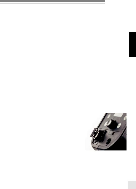
MAINS FUSE
Standard type 5x20mm, use only fast acting F10AH (code 19038) for ELC.
Note: Remove the mains cable before exchanging a blown fuse. Open the little drawer in the mains plug with a screwdriver and replace the fuse with the spare fuse, which is placed in its support in this drawer. (N.B. Please don’t forget to check the correct rating of the fuse!).
7

User Manual 
OPERATING INSTRUCTIONS
The ELC PRO HD compact units are multivoltage and are adapted for operation on 90 – 260V/50
– 60Hz. Before connecting for the irst time, please ensure that your modelling lamp coincides with the correct voltage.
|
1. |
Check that the modelling lamp voltage is correct. |
|
2. |
Insert the mains cable into the MAINS INLET (6) and connect this to a FULLY EARTHED |
|
|
OUTLET. |
EN |
3. |
Turn the unit ON (1). |
|
4. |
DO NOT operate the unit without irst removing the black protective cap. |
|
5. |
Follow the instructions below for itting accessories. |
FITTING ACCESSORIES
6.Always switch the unit off before attaching accessories.
7.Disconnect the mains cable.
8.Mount the lash unit to a tripod and lock the security screw.
9.Turn the locking ring of the relector bayonet anticlockwise to the OPEN position.
10.Insert an accessory and turn it clockwise until you hear it click into place.
11.Turn the locking ring clockwise to close the bayonet, indicated by the white mark on the bayonet ring.
12.Check if the Relector is correctly itted.
13.Reconnect the mains cable and switch the unit on.
Please use only original Elinchrom accessories and relectors. The warranty does not cover damage caused by third party accessories and relectors.
8

User Manual
CONTROL PANEL
11
EN
|
12 |
1 |
13 |
2 |
14 |
3 
4 |
15 |
|
|
5 |
|
6 

16
7 
8
9 

17
10 

9
User Manual 
OVERVIEW OF CONTROLS
|
1. |
On/off button / Standby function (long press to turn off and short press for standby) |
|
2. |
Access menu button |
|
3. |
Left function button / Return function |
|
4. |
Photocell |
|
5. |
Multifunctional control knob and test button / Validate menu function |
EN |
6. |
Mains inlet socket including the main fuse (F10AH 5x20mm). |
|
7. |
Centred umbrella tube for EL Umbrellas – 7mm diameter |
|
8. |
Tilt head |
|
9. |
Extra umbrella itting |
|
10. |
Standard stand socket 5/8” |
|
11. |
Rubberised handle |
|
12. |
Smart OLED display |
|
||
|
13. |
User presets button |
|
14. |
Modelling lamp button |
|
15. |
Right function button / Exit to dashboard |
|
16. |
3.5mm Sync socket (low 5V voltage) |
|
17. |
Knurled clamp screw |
KNOB INFO
DISPLAY |
DESCRIPTION |
|
|
GREEN |
ready |
|
|
GREEN BLINKING |
discharging |
|
|
ORANGE |
charging |
|
|
RED BLINKING |
lashing before 100% ready |
|
|
RED BREATHING |
standby |
|
|
DISPLAY PANEL - DASHBOARD
1.EL-Skyport synchronisation speed
2.EL-Skyport Frequency channel
3. |
EL-Skyport Group number |
1 |
2 |
3 |
4 |
5 |
|
|
|
|||||||||||
4. |
Photocell status |
|
|
|
||||||||||||||||
|
|
|
|
|
|
|
|
|
|
|
|
|
|
|
|
|
|
|
||
5. |
Ready beep |
|
|
|
|
|
|
|
|
|
|
|
|
|
|
|
|
|
|
|
6. |
Power in J |
|
|
|
|
|
|
|
|
|
|
|
|
|
|
|
|
|
|
|
7. |
Flash duration in s |
14 |
|
|
|
|
|
|
|
|
|
|
|
|
|
|
|
|
|
6 |
8. |
Flash function |
|
|
|
|
|
|
|
|
|
|
|
|
|
|
|
|
|
|
|
9. |
Flash function value |
13 |
|
|
|
|
|
|
|
|
|
|
|
|
|
|
|
7 |
||
|
|
|
|
|
|
|
|
|
|
|
|
|
|
|
|
|
8 |
|||
10. |
Increase 1 f-stop |
|
|
|
|
|
|
|
|
|
|
|
|
|
|
|
|
|
|
|
|
|
|
|
|
|
|
|
|
|
|
|
|
|
|
|
9 |
||||
|
|
|
|
|
|
|
|
|
|
|
|
|
|
|
|
|
|
|
|
|
11.Open lash test
12. |
Decrease 1 f-stop |
|
|
|
|
|
|
|
|
|
|
|
|
|
|
|
|
|
13. |
Recycling mode |
|
|
|
|
|
|
|
|
|
|
|
|
|
|
|||
12 |
|
|
11 |
|
|
|
10 |
|
||||||||||
14.Power in f-stop equivalent
10

User Manual
DEDICATED BUTTONS
USER PRESETS
The dedicated user presets button gives you the possibility to easily save all settings of your ELC unit into 4 presets and load these exact same settings later.
DISPLAY |
OPTIONS |
SUB-OPTIONS |
EN |
|
|
|
|
USER PRESETS |
load |
From “preset 1” to “preset 4” |
|
|
|
|
|
|
save |
From “preset 1” to “preset 4” |
|
|
|
|
|
Load the previously saved preset to recall all your desired settings
Save your desired settings to the preset of your choice.
Performing a soft reset, all user presets will keep their values
DISPLAY PANEL - USER PRESETS
1.Preset number (1-4)
2.Modelling lamp settings
3.Modelling lamp status
4.Visual Flash Conirmation status
5.Modelling lamp power in f-stop
6.Proportional modelling lamp value
7.Back to dashboard
8. |
Load selected preset |
18 |
9. |
Save on selected preset |
15 16 17 |
10. |
Flash function value |
14 13 |
11. |
Flash function |
12 |
12. |
Power in f-stop equivalent |
11 |
10 |
13.Photocell status
14.Ready beep
15.EL-Skyport synchronisation speed
16.EL-Skyport Frequency channel
17.EL-Skyport Group number
18.Recycling mode
19.Flash settings
19 |
1 |
|
2 |
|
|
|
|
|
||||||
|
|
|
|
|
|
|
|
|
|
|
|
|
|
|
|
|
|
|
|
|
|
|
|
|
|
|
|
|
|
|
|
|
|
|
|
|
|
|
|
|
|
|
|
|
|
|
|
|
|
|
|
|
|
|
|
|
|
|
|
|
|
|
|
|
|
|
|
|
|
|
|
|
|
|
|
|
|
|
|
|
|
|
|
|
|
|
|
|
|
|
|
|
|
|
|
|
|
|
|
|
|
|
|
|
|
|
|
|
|
|
|
|
|
|
|
|
|
|
|
9 |
8 |
7 |
4
3
5
6
11
User Manual 
MODELLING LAMP
The dedicated modelling lamp button allows you to quickly modiiy anything to do with the modelling light.
|
DISPLAY |
OPTIONS |
SUB-OPTIONS |
|
|
|
|
|
MODELLING LAMP |
VFC |
ON / OFF |
EN |
|
|
|
|
modelling lamp |
off / free / prop |
|
|
|
|
|
|
|
prop mode |
From -1 f-stop to -3.5 f-stop |
|
|
|
|
Turn VFC on when working with multiple units, this will give you a visual conirmation that all lash units have ired.
When using heads of different maximum power you can adjust the modelling lamp to be proportional to the desired value.
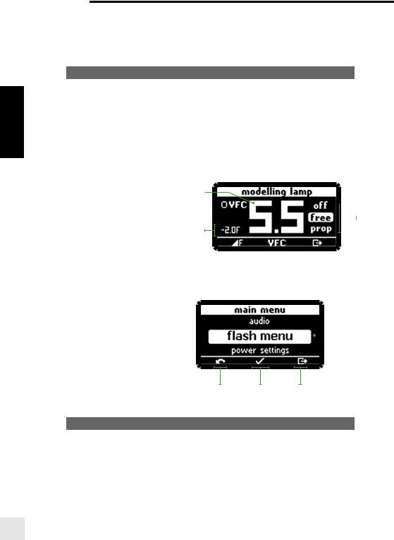
DISPLAY PANEL - MODELING LAMP |
1 |
|
|
|
|
|
|
|
|||||||
|
|
|
|
|
|
|
|
|
|
|
|
|
|
||
|
|
|
|
|
|
|
|
|
|
|
|
|
|
||
1. |
Setting title |
8 |
|
|
|
|
|
|
|
|
|
|
|
|
|
|
|
|
|
|
|
|
|
|
|
|
|
|
|||
|
|
|
|
|
|
|
|
|
|
|
|
|
|||
2. |
Modelling lamp status |
7 |
|
|
|
|
|
|
|
|
|
|
|
|
|
|
|
|
|
|
|
|
|
|
|
|
|
|
|||
3. |
Back to dashboard |
|
|
|
|
|
|
|
|
|
|
|
|
2 |
|
|
|
|
|
|
|
|
|
|
|
|
|
|
|||
|
|
|
|
|
|
|
|
|
|
|
|
|
|||
|
|
|
|
|
|
|
|
|
|||||||
4.Visual Flash Conirmation function
5. Proportional modelling lamp setup 6
6.Proportional modelling lamp value
7. |
Visual Flash Conirmation status |
|
|
|
|
|
|
|
|
|
|
|
|
|
|
|
|
|
|
|
|
|
|
8. |
Modelling lamp power in f-stop |
5 |
4 |
|
|
|
|
|
3 |
|
|
||||||||||||
|
|
|
|
|
|
|
|
|
|
|
|
|
|
|
|
|
|
|
|
|
|||
MENU FEATURES |
|
|
|
1 |
|
|
|
|
|
|
|
|
|
|
|
|
|
|
|||||
|
|
|
|
|
|
|
|
|
|
|
|
|
|
|
|
|
|
|
|
|
|||
|
|
|
|
|
|
|
|
|
|
|
|
|
|
|
|
|
|
|
|
|
|
|
|
DISPLAY PANEL - MAIN MENU
1.Menu title
2. |
Current selection |
|
|
2 |
|
|
3.Back to dashboard
4.Enter
5. Back
PHOTOCELL |
5 |
4 |
3 |
|
The photocell options allow you to switch the photocell on and off and to set up pre-lash for perfect synchronization with speedlites.
DISPLAY |
OPTIONS |
SUB-OPTIONS |
|
|
|
PHOTOCELL |
on |
|
|
|
|
|
off |
|
|
|
|
|
Pre-lash |
From 1 to 10 pre-lashes |
|
|
|
|
set up pre-lash |
auto / manual / block time / |
|
timeframe |
|
|
|
|
|
|
|
When the photocell is on, the lash unit will trigger at any recognised lash impulse.
12

 User Manual
The pre-lash option can be adjusted manually if the number of pre-lashes of the speedlite is known. Otherwise, simply choose “set up pre-lash” and release a speedlite exposure. The
number of pre-lashes will be automatically detected and stored. You are now ready to work with your speedlites.
MANUAL PRE-FLASH SETUP (FOR ADVANCED USERS) |
|
|
In some cases depending on the technology of the speedlite unit, the automatic pre-lash |
|
|
detection may not work. In this case you can try a manual setup. |
EN |
|
• manual: enter the number of pre-lashes from 1 to 10. |
||
|
||
• block time: set the delay between each pre-lash from 0.5 to 5 ms. |
|
• imeframe: set the time window in which all pre-lashes, including the main lash, are released.
Note: We cannot suggest any values or settings here; this depends on the speedlite unit and must be tested until the correct synchronisation between the lash unit and the speedlite is achieved.
EL-SKYPORT TRANSCEIVER FEATURES & SETUP
The EL-Skyport options allow you to select the synchronisation speed and to deine group and channel settings.
DISPLAY |
OPTIONS |
SUB-OPTIONS |
|
|
|
SKYPORT |
off (r.0) |
|
|
|
|
|
normal (r.1) |
|
|
|
|
|
speed (r.2) |
|
|
|
|
|
group |
From “group 1” to “group 4”. |
|
|
|
|
channel |
From “chan. 1” to “chan. 8”. |
|
|
|
If you work with the EL-Skyport system you can easily choose the synchronization speed. The “normal” synchronization mode is good when long distances are needed whereas the “speed” synchronization should be used when higher shutter speeds are needed with enabled digital cameras.
Finally you can choose in which group and frequency you would like to work. Change group settings to have a better control between main light and second lights.
Change frequency channel to avoid interference.
AUDIO
The audio options give you the choice of different settings for when the capacitors are 100% charged and the unit is ready to lash.
DISPLAY |
OPTIONS |
SUB-OPTIONS |
|
|
|
AUDIO |
beep volume |
From “off” to “max”. |
|
|
|
|
beep tone |
From “0” to “7”. |
|
|
|
|
key click |
From “off” to “max”. |
|
|
|
The volume of the beep sound for when the unit is ready to lash can be adjusted, enabling you to work silently if needed
The beep tone can be chosen to improve acoustical recognition for when all lashes have ired and are recycled.
Finally the volume of the key click can also be adjusted to your liking.
13

User Manual 
FLASH MODE
The lash mode menu enables you to conigure your ELC unit to suit your style of shooting.
|
DISPLAY |
OPTIONS |
SUB-OPTIONS |
|
|
|
|
|
|
|
FLASH MODE |
default |
|
|
|
|
|
|
|
EN |
sequence |
unit address / total units/ seq. |
||
timeout |
||||
|
||||
|
|
|
|
|
|
|
delayed |
set delay (in ms) |
|
|
|
|
|
|
|
|
strobo |
frequency / duration |
|
|
|
|
|
|
|
|
Setup the activated mode |
|
|
|
|
|
|
|
Stay on default if you wish to do everyday lash photography.
SEQUENCE SETUP
Use sequence mode to catch a moving sequence with a number of indexed units, for example, of a jumping person in up to 20 different images. The following setup must be programmed in order to use the features.
•unit address: Every unit requires its own address; every time a trigger is released the corresponding lash unit will respond. Up to 20 units can be addressed.
•total units: Indicates the total number of addressed lash units.
•sequence timeout: Time after which the sequence restarts back to irst addressed unit. The timeout can be programmed from 0.1s to 5s. This setting is necessary to lash the addressed units in the right order.
DELAY SETUP
Set a delay to your ELC unit to lash with a speciic delay after triggering (e.g. second curtain).
•Set delay (in ms): Time in which the unit should ire a lash after the camera shutter has been opened. The delay time can programmed from 1ms (0.001 s.) to 10000ms (10 s.). Please see the suggested values in the table page 21 if you want to have second curtain sync via skyport.
Note: to ine-tune the miliseconds, the scale can be modiied in 1, 10, 100 and 1000 steps. Press the User preset button after each digit to multply by 10 and use the Modelling lamp button to reduce by factor 10. This option is only active in the lash delay setup menu.
STROBO SETUP
Take an image with stroboscopic effects and open camera shutter. The overlapping moving sequence is visible in one image.
•Frequency: Number of lashes per second. Programmable from 1 to 20Hz.
•Duration window: Time during of the moving sequence you wish to capture. Programmable from 0.5 s. to 5 s.
Note: The unit must be set in fast recycling time in the “power settings” menu. If the unit’s master button LED lashes in red, this means the recycling time cannot follow the settings. Please reduce the Hz setting or the lash power to a lower value.
14

User Manual
POWER SETTINGS
Power settings help you deine standby and when to auto-off to save energy. You can also deine recycling time depending on the electrical environment.
DISPLAY |
OPTIONS |
SUB-OPTIONS |
|
|
|
|
|
POWER SETTINGS |
auto standby |
From [off] to [60min] in steps of |
|
5 min - default 30 minutes. |
|
||
|
|
EN |
|
|
|
|
|
|
auto-off |
From [off] to [10 hrs] in steps of |
|
|
|
||
|
1 hour - default 5 hours. |
|
|
|
|
|
|
|
|
|
|
|
recycling time |
slow / default / fast |
|
|
|
|
|
The standby option lets you decide after how long the unit goes into standby mode, enabling you to quickly turn the unit back on when needed.
The auto-off option does just what its name suggests. When left unattended the unit will switch off automatically after the indicated time.
Recycling time can be important depending on where you are working. If you are working outdoors with low eficient battery inverter (e.g. camping battery) choose slow to not draw too much current. Otherwise just go for fast recycling.
STATISTICS
Check lifetime of the unit and the lashtube.
DISPLAY |
OPTIONS |
SUB-OPTIONS |
|
|
|
|
|
STATISTICS |
unit usage |
lifetime / actual usage / power- |
|
on |
|||
|
|
||
|
|
|
|
|
lash count |
total / actual / lashtube |
|
|
|
|
You can easily check the current usage of the unit and the lashtube. Very useful for servicing or second-hand retail.
Note: It is possible to reset lashtube counter. E.g. when lashtube has been replaced with a new one!
TROUBLESHOOTING
SOFT RESET
To reset all settings to default values, push the left and right buttons at the same time and hold for at least 1 second. The unit will reboot and will clear all working parameters.
This will not delete the “User Preset” data which is restored in the preset menu nor will it reset the counter in the “Statistics” menu for “total lifetime”, “total lash amount” and “power on”.
FLASHTUBE REPLACEMENT
Flashtubes have a long life with general use however multi-lashing in long sequences can cause overheating of the electrodes leading to premature ageing. If the lashtube is broken or cracked, triggers only sporadically, or you notice an important colour temperature shift, it could be that the lashtube needs replacing.
15
User Manual 
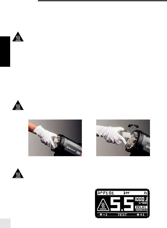
TO REPLACE THE FLASHTUBE:
• Switch the unit off
• Remove the mains cable
• Take the unit from its stand and lay it horizontally on a rigid surface. It will need to be held irmly whilst removing and replacing the lashtube.
• Allow the lashtube and modelling lamp to cool down and wait for the unit to discharge for min. 30 minutes.
EN |
• Carefully remove and store the modelling lamp. They can be very hot. |
|
|
||
|
a. |
Always use a protective glove to remove the lashtube |
|
b. |
Pull the lashtube irmly out of the terminals |
|
c. |
If the tube is broken, use security gloves to avoid cutting yourself and use an insulated |
|
|
tool to pull out the electrodes. Never touch the metal electrodes and ensure that the unit |
|
|
has been disconnected from the mains for min. 30 minutes. |
• Take the new lashtube. Insulated tissues or security gloves MUST BE USED.
• Any contact with your ingers on the tube, can cause dark markings on the tube when used.
• Check that the tube is correctly aligned (central) and that the trigger contact is gripping the tube.
• Re-connect and test the unit as usual.
• Optionnaly you can reset the lashtube counter in the statistics menu.
TO REPLACE THE GLASS DOME
• To remove the dome, switch the unit off, disconnect the mains cable and leave it to cool down for 30 minutes.
• Remove any accessories.
• Turn the glass dome anticlockwise and pull. Please use gloves for safety precautions.
• Reit the glass dome by turning the dome clockwise until is locked.
QUICK FAQ
My modelling lamp switches off: An overheat protection shuts the Halogen lamp down at high internal temperature. After cooling down, the Halogen lamp will switch back on automatically.
My unit turned off by itself: A thermal cutout protects internal electronic components. At high ambient temperatures or after rapid or frequent use, the thermal cutout may interrupt the capacitor charge.
My unit is recycling slower:
The over-heating protection electronics will slow down the recycling speed after the unit has been intensively used. The display will show a warning symbol. After cooling down, the unit will switch back automatically to fast recycling speed.
16

|
|
|
|
User Manual |
|
|
|
|
|
|
|
||
|
|
|
|
|
||
ERROR MANAGEMENT |
|
|
|
|
||
|
|
|
|
|
|
|
|
ERROR |
DESCRIPTION |
SOLUTION |
|
||
|
NUMBER |
|
||||
|
|
|
|
|
|
|
|
|
|
|
|
|
|
|
|
|
Switch the unit off, wait 2 minutes and switch |
|
||
1 |
Capacitor over voltage |
the unit on again. If the error shows up again |
|
|||
the unit requires a check up at an authorized |
|
|||||
|
|
|
|
|||
|
|
|
Elinchrom service centre. |
EN |
||
|
|
|
|
|
|
|
|
|
|
Wait until the unit has cooled down. |
|||
|
|
|
|
|||
2 |
Over heat |
The unit will switch back to the normal |
|
|||
operation as soon as the temperature |
|
|||||
|
|
|
|
|||
|
|
|
decreases to a normal working level. |
|
||
3Discharge error
|
|
Switch the unit off, wait 2 minutes and switch |
|
4 |
Charge timeout error |
||
the unit on again. If the error shows up again |
|||
|
|
||
5 |
Charge hold error |
the unit requires a check up at an authorized |
|
Elinchrom service centre. |
|||
|
|
||
6 |
Fan error |
||
|
|||
|
|
|
|
10 |
Supply input voltage too high |
The unit has detected a mains supply fault. |
|
|
|
||
11 |
Supply input voltage too low |
Please check the mains/battery inverter |
|
|
|
supply. |
|
|
Supply under voltage detected until |
||
12 |
It could be not working correctly. |
||
charge |
|||
|
|
||
|
|
|
|
13 |
Over current detection |
|
|
|
|
|
|
15 |
Temperatur sensor “Heat Sink” not |
|
|
connected |
|
||
|
Switch the unit off, wait 2 minutes and switch |
||
|
|
||
16 |
Temperatur sensor “Front”not |
the unit on again. If the error shows up again |
|
connected |
the unit requires a check up at an authorized |
||
|
|||
|
|
Elinchrom service centre. |
|
17 |
Temperatur sensor “Charge” not |
||
|
|||
connected |
|
||
|
|
||
|
|
|
|
20 |
Power Board not connected / found |
|
|
|
|
|
|
|
|
Switch the unit off, wait 10 minutes and |
|
24 |
Capacitor voltage symmetry error |
switch the unit on again. If the error shows |
|
up again the unit requires a check up at an |
|||
|
|
||
|
|
authorized Elinchrom service centre. |
|
|
|
|
|
28 |
Flash tube after glow |
Switch the unit off, wait 2 minutes and switch |
|
|
|
the unit on again. If the error shows up again |
|
29 |
Auto Ignition on Charge |
||
please change lashtube. If it still happens |
|||
|
|
||
|
|
||
30 |
Auto Ignition on Ready |
the unit requires a check up at an authorized |
|
Elinchrom service centre. |
|||
|
|
17

User Manual 
TECHNICAL DATA
|
|
COMPACT PROFESSIONAL |
ELC PRO HD 500 |
|
ELC PRO HD 1000 |
|
|
|
|
|
|
|
|
ENERGY (WS/J) |
500 |
|
1000 |
|
|
|
|
|
|
|
|
F-STOP (1M, 100 ISO, REFLECTOR |
64.8 |
|
90.8 |
|
48°) |
|
|||
|
|
|
|
||
EN |
|
|
|
|
|
|
POWER RANGE F-STOP |
7 |
|
8 |
|
|
|
|
|
|
|
|
|
POWER RANGE WS |
7-500 |
|
7-1000 |
|
|
|
|
|
|
|
|
POWER RANGE DISPLAY |
0.3 - 6.3 |
|
0.3 – 7.3 |
|
|
|
|
|
|
|
|
POWER INCREMENTS IN F-STOP |
Adjusted by precise multifunctional power knob in 1/10 steps |
||
|
|
|
|
|
|
|
|
FLASH DURATION T0.5 IN S. |
Min. power: 1/2940 |
|
Min. power: 1/2780 |
|
|
Max. power: 1/2330 |
|
Max. power: 1/1430 |
|
|
|
|
|
||
|
|
|
|||
|
|
|
|
|
|
|
|
BEST FLASH DURATION AT POWER: |
3.1 (1/5000) |
|
3.6 (1/5260) |
|
|
|
|
|
|
|
|
RECYCLING 230 V IN S. |
Slow: 2.0 / Default: 0.75 / Fast: 0.6 |
|
Slow: 4.0 / Default: 1.5 / Fast: 1.2 |
|
|
|
|
|
|
|
|
RECYCLING 115 V IN S. |
Slow: 2.5 / Default: 0.9 / Fast: 0.7 |
|
Slow: 5.0 / Default: 1.8 / Fast: 1.4 |
|
|
|
|
|
|
|
|
MAX. FLASH PER SEC. AT MIN. |
|
20 |
|
|
|
POWER |
|
||
|
|
|
|
|
|
|
|
|
|
|
|
|
|
COLOUR TEMPERATURE IN °K |
|
5500 |
|
|
|
|
|
|
|
|
|
AUTO POWER DUMPING |
Adjusts power settings automatically |
||
|
|
|
|
|
|
|
|
POWER STABILITY |
|
± 0.1% |
|
|
|
|
|
|
|
|
|
VOLTAGE |
Multi-voltage 90 - 265 V |
||
|
|
|
|
|
|
|
|
MODELLING LAMP MODE |
Off, free, proportional, VFC: -0.5 to -2.0 f-stop |
||
|
|
|
|
|
|
|
|
MODELLING LAMP 230 V |
300 W / GX 6.35 - 23022 |
||
|
|
|
|
|
|
|
|
MODELLING LAMP 115 V |
300 W / GX 6.35 - 23030 |
||
|
|
|
|
|
|
|
|
FLASHTUBE |
S-Type, Omega Plug-in, user replaceable - 24084 |
||
|
|
|
|
|
|
|
|
EL-SKYPORT (BUILT-IN) |
Integrated transceiver, 8 Frequency Channels and 4 Groups with full RX |
||
|
|
|
features |
||
|
|
|
|
||
|
|
|
|
|
|
|
|
SYNC VOLTAGE |
5 V (compatible with all cameras) |
||
|
|
|
|
|
|
|
|
SYNC SOCKET |
3.5 mm Jack |
||
|
|
|
|
|
|
|
|
FAN COOLED |
Electronically intelligent temperature controlled fan. |
||
|
|
|
|
|
|
|
|
UMBRELLA FITTING |
Centred tube for EL-umbrellas ø 7 mm. |
||
|
|
Stand bracket with extra umbrella itting for larger umbrella shafts |
|||
|
|
|
|||
|
|
|
|
|
|
|
|
GLASS DOME FROSTED, OPTIONAL |
|
24917 |
|
|
|
|
|
|
|
|
|
MAX. POWER CONSUMPTION IN W |
Slow: during charge: 350 |
||
|
|
Default: during charge: 700 |
|||
|
|
(230 V / 50 HZ / MOD LAMP OFF) |
|||
|
|
Fast: during charge: 875 |
|||
|
|
|
|||
|
|
|
|
|
|
|
|
MAX. POWER CONSUMPTION IN W |
Slow: during charge: 250 |
||
|
|
Default: during charge: 500 |
|||
|
|
(115 V / 60 HZ / MOD LAMP OFF) |
|||
|
|
Fast: during charge: 625 |
|||
|
|
|
|||
|
|
|
|
|
|
|
|
PURE SINE BATTERY CONVERTER |
600 with Halogen |
||
|
|
DC/AC : SLOW CHARGE (W) |
|||
|
|
|
|
|
|
|
|
|
|
|
|
|
|
DIMENSIONS |
31.5 x 14 x 21 cm |
||
|
|
(WITH PROTECTIVE CAP) |
|||
|
|
|
|
|
|
|
|
|
|
|
|
18

|
|
|
|
User Manual |
|
|
|
|
|
||
|
|
|
|
||
|
|
|
|
|
|
|
WEIGHT |
2.35 kg (5.2 lb.) |
2.9 kg (6.4 lb.) |
||
|
|
|
|
|
|
|
SUPPLIED WITH |
Mains cable, sync cable, lashtube, modelling lamp, |
|||
|
glass dome, protective cap and relector 16 cm 90° |
||||
|
|
||||
|
|
|
|
|
|
|
CODE N° |
20613.1 |
20616.1 |
|
|
|
|
|
|
|
|
FLASH DURATION ON DIFFERENT ENERGY LEVELS
EN
FLASH DURATION (T.05 IN S) |
F-STOP VALUE / ENERGY OUTPUT (WS) |
||
|
|
||
ELC PRO HD 500 |
ELC PRO HD 1000 |
||
|
|||
|
|
|
|
/ |
1/1430 |
7.3 / 1045 |
|
|
|
|
|
/ |
1/1380 |
7.2 / 975 |
|
|
|
|
|
/ |
1/1320 |
7.1 / 909 |
|
|
|
|
|
/ |
1/1270 |
7.0 / 849 |
|
|
|
|
|
/ |
1/1220 |
6.9 / 792 |
|
|
|
|
|
/ |
1/1160 |
6.8 / 739 |
|
|
|
|
|
/ |
1/1140 |
6.7 / 689 |
|
|
|
|
|
/ |
1/1130 |
6.6 / 643 |
|
|
|
|
|
/ |
1/1110 |
6.5 / 600 |
|
|
|
|
|
/ |
1/1090 |
6.4 / 560 |
|
|
|
|
|
1/2330 |
1/1640 |
6.3 / 522 |
|
|
|
|
|
1/2270 |
1/1610 |
6.2 / 487 |
|
|
|
|
|
1/2220 |
1/1590 |
6.1 / 455 |
|
|
|
|
|
1/2130 |
1/1560 |
6.0 / 424 |
|
|
|
|
|
1/2080 |
1/1540 |
5.9 / 396 |
|
|
|
|
|
1/2040 |
1/1520 |
5.8 / 369 |
|
|
|
|
|
1/2020 |
1/1510 |
5.7 / 345 |
|
|
|
|
|
1/3230 |
1/1500 |
5.6 / 322 |
|
|
|
|
|
1/3170 |
1/1500 |
5.5 / 300 |
|
|
|
|
|
1/3130 |
1/1490 |
5.4 / 280 |
|
|
|
|
|
1/3130 |
1/2700 |
5.3 / 261 |
|
|
|
|
|
1/3080 |
1/2600 |
5.2 / 244 |
|
|
|
|
|
1/3080 |
1/2620 |
5.1 / 227 |
|
|
|
|
|
1/3030 |
1/2580 |
5.0 / 212 |
|
|
|
|
|
1/3030 |
1/2540 |
4.9 / 198 |
|
|
|
|
|
1/2990 |
1/2630 |
4.8 / 185 |
|
|
|
|
|
1/2990 |
1/2730 |
4.7 / 172 |
|
|
|
|
|
1/2940 |
1/2830 |
4.6 / 161 |
|
|
|
|
|
1/2940 |
1/2930 |
4.5 / 150 |
|
|
|
|
|
1/2900 |
1/3030 |
4.4 / 140 |
|
|
|
|
|
1/2900 |
1/3130 |
4.3 / 131 |
|
|
|
|
|
19
User Manual 
|
|
1/2860 |
1/3060 |
4.2 / 122 |
|
|
|
|
|
|
|
|
1/2860 |
1/2980 |
4.1 / 114 |
||
|
|
|
|
|
|
|
1/2820 |
1/2910 |
4.0 / 106 |
||
|
|
|
|
|
|
|
1/2820 |
1/2840 |
3.9 / 99 |
||
|
|
|
|
|
|
|
1/2780 |
1/2770 |
3.8 / 92 |
||
|
|
|
|
|
|
|
1/2780 |
1/2700 |
3.7 / 86 |
||
EN |
|||||
|
|
|
|
||
1/2740 |
1/5260 |
3.6 / 80 |
|||
|
|||||
|
|
|
|
|
|
|
1/2740 |
1/5180 |
3.5 / 75 |
||
|
|
|
|
|
|
|
1/2700 |
1/5090 |
3.4 / 70 |
||
|
|
|
|
|
|
|
1/2700 |
1/5000 |
3.3 / 65 |
||
|
|
|
|
|
|
|
1/2700 |
1/4950 |
3.2 / 61 |
||
|
|
|
|
|
|
|
1/5000 |
1/4910 |
3.1 / 57 |
||
|
|
|
|
|
|
|
1/5000 |
1/4860 |
3.0 / 53 |
||
|
|
|
|
|
|
|
1/4880 |
1/4810 |
2.9 / 49 |
||
|
|
|
|
|
|
|
1/4760 |
1/4760 |
2.8 / 46 |
||
|
|
|
|
|
|
|
1/4650 |
1/4640 |
2.7 / 43 |
||
|
|
|
|
|
|
|
1/4650 |
1/4520 |
2.6 / 40 |
||
|
|
|
|
|
|
|
1/4650 |
1/4410 |
2.5 / 38 |
||
|
|
|
|
|
|
|
1/4550 |
1/4290 |
2.4 / 35 |
||
|
|
|
|
|
|
|
1/4440 |
1/4170 |
2.3 / 33 |
||
|
|
|
|
|
|
|
1/4350 |
1/4130 |
2.2 / 30 |
||
|
|
|
|
|
|
|
1/4260 |
1/4100 |
2.1 / 28 |
||
|
|
|
|
|
|
|
1/4170 |
1/4070 |
2.0 / 27 |
||
|
|
|
|
|
|
|
1/4080 |
1/4030 |
1.9 / 25 |
||
|
|
|
|
|
|
|
1/4000 |
1/4000 |
1.8 / 23 |
||
|
|
|
|
|
|
|
1/3920 |
1/3970 |
1.7 / 22 |
||
|
|
|
|
|
|
|
1/3850 |
1/3940 |
1.6 / 20 |
||
|
|
|
|
|
|
|
1/3770 |
1/3910 |
1.5 / 19 |
||
|
|
|
|
|
|
|
1/3700 |
1/3880 |
1.4 / 17 |
||
|
|
|
|
|
|
|
1/3640 |
1/3850 |
1.3 / 16 |
||
|
|
|
|
|
|
|
1/3570 |
1/3720 |
1.2 / 15 |
||
|
|
|
|
|
|
|
1/3510 |
1/3600 |
1.1 / 14 |
||
|
|
|
|
|
|
|
1/3450 |
1/3470 |
1.0 / 13 |
||
|
|
|
|
|
|
|
1/3330 |
1/3350 |
0.9 / 12 |
||
|
|
|
|
|
|
|
1/3280 |
1/3230 |
0.8 / 12 |
||
|
|
|
|
|
|
|
1/3230 |
1/3140 |
0.7 / 11 |
||
|
|
|
|
|
|
|
1/3170 |
1/3050 |
0.6 / 10 |
||
|
|
|
|
|
|
|
1/3130 |
1/2960 |
0.5 / 9 |
||
|
|
|
|
|
|
|
1/3030 |
1/2870 |
0.4 / 9 |
||
|
|
|
|
|
|
|
1/2940 |
1/2780 |
0.3 / 8 |
||
|
|
|
|
|
|
20

 User Manual
SUGGESTED VALUE TO SET ON THE ELC IN DELAYED MODE*
SYNC SPEED ON CAMERA |
EQUIVALENT IN MS |
SUGGESTED VALUE |
|
|
|
|
|
|
|
1/60 |
16.6 |
9 |
|
|
|
|
|
|
|
1/50 |
20 |
12 |
|
|
|
|
|
|
|
1/40 |
25 |
17 |
|
EN |
1/30 |
33.3 |
23 |
|
|
|
|
|
|
|
1/25 |
40 |
30 |
|
|
|
|
|
|
|
1/20 |
50 |
40 |
|
|
|
|
|
|
|
1/15 |
66.6 |
52 |
|
|
|
|
|
|
|
1/13 |
77 |
68 |
|
|
|
|
|
|
|
1/10 |
100 |
90 |
|
|
|
|
|
|
|
1/8 |
125 |
115 |
|
|
|
|
|
|
|
1/6 |
166.6 |
145 |
|
|
|
|
|
|
|
1/5 |
200 |
185 |
|
|
|
|
|
|
|
1/4 |
250 |
235 |
|
|
|
|
|
|
|
0.3" |
300 |
290 |
|
|
|
|
|
|
|
0.4" |
400 |
170 |
|
|
|
|
|
|
|
0.5" |
500 |
470 |
|
|
|
|
|
|
|
0.6" |
600 |
580 |
|
|
|
|
|
|
|
0.8" |
800 |
750 |
|
|
|
|
|
|
|
1" |
1000 |
950 |
|
|
|
|
|
|
|
1.3" |
1300 |
1200 |
|
|
|
|
|
|
|
1.6" |
1600 |
1500 |
|
|
|
|
|
|
|
2" |
2000 |
1900 |
|
|
|
|
|
|
|
2.5" |
2500 |
2400 |
|
|
|
|
|
|
|
3.2" |
3200 |
2900 |
|
|
|
|
|
|
|
4" |
4000 |
3800 |
|
|
|
|
|
|
|
5" |
5000 |
4800 |
|
|
|
|
|
|
|
6" |
6000 |
5800 |
|
|
|
|
|
|
|
8" |
8000 |
7700 |
|
|
|
|
|
|
|
10" |
10000 |
9700 |
|
|
|
|
|
|
|
* tested with canon EOS 5D. Suggested for fullframe camera.
21

User Manual 
WARRANTY
|
ELINCHROM WARRANTY |
|
|
ELINCHROM products will be repaired free of charge, from the date of purchase by the local Agent / |
|
|
Distributor if during a period of 24 months its working order is impaired through a manufacturing or material |
|
|
defect. The faulty product should be immediately sent back to the Authorized Dealer from where the item was |
|
|
purchased or to the Authorized Service Agent. |
|
EN |
||
Please read the following warranty conditions, limitations and exclusions: |
||
|
||
|
• For all warranty cases proof of purchase / invoice is required. |
|
|
• The Elinchrom Distributor covers the warranty of national purchased goods in his country. Please ind a |
|
|
list of national Distributors and the Authorized Dealers for the country in question at www.elinchrom.com. |
|
|
• A “Limited Warranty” affects all Elinchrom products, which are purchased from international Web Stores, |
|
|
or Dealers and their Web Stores, which are not listed as a national Elinchrom Dealer. This “Limited |
|
|
Warranty” covers all spare parts guaranteeing the customer they stay free of charge however the labour |
|
|
for the repair may be chargeable. |
|
|
• The full warranty can only be fulilled if the faulty goods are returned to the vendor. Note: Transportation or |
|
|
shipping costs outside of the domestic country are not covered. There might also be a long delay due to |
|
|
transportation and customs if products have to be returned to the country where they came from. |
|
|
GENERAL WARRANTY INFORMATION |
FLASHTUBES
•Broken, misused or over-abused lashtubes are not covered by the warranty.
FLASH ELECTRONICS AND MECHANICS
24 months warranty for electronic and mechanic parts, except capacitors, which are used in industrial applications like production control or serial imaging etc..
WARRANTY EXCLUSIONS
Consumables such as Sync Cords, Fuses and Batteries for Remote Devices are excluded from the warranty.
MODELLING / PILOT LAMPS
•Lamps are generally excluded from the warranty.
•Please see the lamp manufacturers regulations.
TRANSPORTATION DAMAGES
•Damages, caused by transportation and shipping must be claimed to the shipping service.
•Damaged packaging or rattling parts inside the box such as broken lashtubes or lamps should be checked whilst the shipping service is present.
MISUSING
This warranty does not cover equipment, which has been:
•misused and abused in general
•dismantled, modiied, or repaired by a non-authorized Service Agent
•used under extreme cold, hot, dusty or wet / humid conditions.
•damaged by third party accessories, lashtubes, lamps, cables or other parts.
UNSATISFACTORY OPERATION
•No responsibilities can be accepted for any damage, resulting from unsatisfactory operation of the equipment, such as wasted materials, model costs or other expenses.
22

|
|
Gebrauchsanleitung |
|||
|
|
||||
|
|
||||
|
INHALT |
|
|
|
|
|
EINLEITUNG |
24 |
|
|
|
|
|
|
|
|
|
|
KONFORMITÄTSERKLÄRUNG, RECYCLING, CE |
25 |
|
|
|
|
|
|
|
|
|
|
ZEICHENERKLÄRUNG |
26 |
|
|
|
|
|
|
|||
|
|
|
|
|
DE |
|
SICHERHEITSVORSCHRIFTEN |
27 |
|
|
|
|
|
|
|
|
|
|
VOR DEM EINSCHALTEN |
29 |
|
|
|
|
|
|
|
|
|
|
KONTROLL DISPLAY |
31 |
|
|
|
|
|
|
|
|
|
|
VORDEFINIERTE TASTER |
33 |
|
|
|
|
|
|
|
|
|
|
MENÜFUNKTIONEN |
34 |
|
|
|
|
|
|
|
|
|
|
FEHLERBEHEBUNG |
38 |
|
|
|
|
|
|
|
|
|
|
TECHNISCHE DATEN |
40 |
|
|
|
|
|
|
|
|
|
|
BLITZDAUER BEI UNTERSCHIEDLICHEN LEISTUNGSEINSTELLUNGEN |
41 |
|
|
|
|
|
|
|
|
|
|
EMPFOHLENE EINSTELLWERTE FÜR DEN DELAYED MODE |
43 |
|
|
|
|
(VERZÖGERUNGSMODUS) |
|
|
||
|
|
|
|
||
|
|
|
|
|
|
|
GARANTIE |
44 |
|
|
|
|
|
|
|
|
|
|
GARANTIEAUSSCHLÜSSE |
44 |
|
|
|
|
|
|
|
|
|
23

Gebrauchsanleitung
|
EINLEITUNG |
|
Lieber Fotograf und Fotoenthusiast |
|
Herzlichen Dank, dass Sie sich für Elinchrom entschieden haben. |
|
ELINCHROM verwendet für seine Produkte nur hochwertige und geprüfte Baukomponenten. |
|
Die Endkontrolle sichert die Einhaltung des Qualitätsstandards und garantiert eine einwandfreie |
|
Funktion. Elinchrom Blitzlichtprodukte wurden entsprechend der gültigen Normen entwickelt und |
|
produziert um Ihre Sicherheit zu gewähren. Wir hoffen, dass Sie mit diesem Gerät vollkommen |
DE |
zufrieden sein werden. |
|
|
|
Weitere Details, Gebrauchsanweisungen, Technische Daten und die letzten Neuheiten über |
|
Elinchrom erhalten Sie auf unserer Webseite elinchrom.com. |
|
Technische Daten und Funktionen der Elinchrom Produkte können sich ständig im Zuge |
|
der Weiterentwicklung ohne Voranmeldung ändern. Toleranzen der technischen Daten für |
|
Bauelemente und Messwerte entsprechen den IEC und EC Normen. Die Daten können durch |
|
Toleranzen der Bauelemente schwanken und sind als Richtwerte zu verstehen und nicht im |
|
rechtlichen Sinne als zugesicherte Eigenschaften. Keine Haftung für Druckfehler. |
|
Um einwandfreie Ergebnisse zu erzielen und die zuverlässige Funktion für lange Zeit zu sichern, |
|
lesen Sie bitte die nachstehenden Gebrauchsund Sicherheitsinformationen. |
|
Ihr Elinchrom Team |
|
Finden Sie aktuelle Gebrauchsanleitungen unter www.elinchrom.com/support, Sie laden mit der |
|
Elinchrom iOS App die letzte Version mit folgendem QR Code: |
http://bc.gs/27
24

Gebrauchsanleitung
KONFORMITÄTSERKLÄRUNG
USA UND CANADA
Dieses Gerät entspricht Paragraph 15 der FCC Normen, die folgende Punkte beinhalten:
1.Dieses Gerät verursacht keine Interferenzen die nicht den Normen entsprechen.
2.Dieses Gerät akzeptiert jegliche Interferenzen, auch die, die eventuell Störungen verursachen können.
DE
Produktname: |
ELC Pro HD 500 / 1000 |
|
|
|
|
Firmenname: |
ELINCHROM |
|
|
|
|
Model Nr. |
20613.1 – ELC Pro HD 500 |
|
20616.1 – ELC Pro HD 1000 |
||
|
||
|
|
|
Name der Verantwortlichen |
Elinchrom LTD |
|
Av. De Longemalle11 |
||
Firma: |
||
1020 Renens / Switzerland |
||
|
||
|
|
|
Telefon: |
+41 21 637 26 77 |
|
|
|
|
Fax: |
+41 21 637 26 81 |
|
|
|
|
Email: |
elinchrom@elinchrom.ch |
|
|
|
FCC CLASS B COMPLIANCE STATEMENT
Elinchrom LTD erklärt hiermit, dass die Geräte mit den genannten
Modellnamen nach den einschlägigen EU, DIN, IEC, FCC Normen geprüft und getestet wurden. Sie entsprechen allen Vorschriften und alle notwendigen Prüfungen wurden durchgeführt um die Einhaltung und Sicherheit auch während der Serienproduktion zu garantieren.
Elinchrom LTD ist nicht verantwortlich für Radio oder TV Interferenzen und Störungen, wenn Geräte oder Module ohne Berechtigung modiiziert wurden oder wenn Komponenten und Kabel verwendet werden die nicht von Elinchrom LTD freigegeben wurden.
25
Gebrauchsanleitung
CE MARKING
Dieses Studioblitzgerät entspricht den Anforderungen der EMV Richtlinie (EMV 2004/108/EC) Elektromagnetische Verträglichkeit” und (2006/95/EC) “Niederspannungsrichtlinie”.
ENTSORGUNG UND RECYCLING
Dieses Gerät wurde weitestgehend aus Materialien hergestellt, die umweltschonend entsorgt und einem fachgerechten Recycling zugeführt werden können. Nach seinem Gebrauch wird das Gerät zurückgenommen, um es einer Wiederverwendung bzw. wertstoflichen Verwertung zuzuführen,
DE soweit es in einem Zustand zurückgegeben wird, der dem bestimmungsgemäßen Gebrauch entspricht. Nicht verwertbare Geräteteile werden sachgemäß entsorgt.
ZEICHENERKLÄRUNG
In dieser Anleitung werden Symbole verwendet, die auf gesundheitsgefährdende Gefahren hinweisen und auch das Produkt bei Fehlbedienung zerstören könnten. Die Symbole haben folgende Bedeutung haben:
RECYCLING, WIDERVERWERTUNG
ENTSORGUNG
Das Produkt muss nach seiner Laufzeit entsprechend der WEEE Bestimmungen dem Elinchrom Händler kostenfrei zurückgegeben werden. Bitte die Landesvorschriften beachten.
SICHERHEITSHINWEISE
Kennzeichnet Hinweise, bei deren Nichtbeachtung Ihre Gesundheit, die Funktionsfähigkeit oder die Sicherheit Ihrer Daten gefährdet.
INFORMATION
Kennzeichnet zusätzliche Informationen und Tipps.
CE
Kennzeichnet die Einhaltung der EMV Richtlinien.
WARNUNG VOR ELEKTRISCHEM SCHLAG – HOHE ELEKTRISCHE SPANNUNGEN.
WARNUNG VOR HEISSEN OBERFLÄCHEN UND VERBRENNUNGSGEFAHR.
26
Gebrauchsanleitung
SICHERHEITSVORSCHRIFTEN
SICHERHEITSINFORMATIONEN FÜR STUDIO, OUTDOOR UND UNIVERSELLE VERWENDUNG.
Blitzgeräte sind leistungsstarke Lichtanlagen. Seien Sie sich bewusst über die Gefahren und Unannehmlichkeiten die Blitzgeräte bei Personen und Kindern hervorrufen könnten.
Blitzanlagen von nicht autorisierten Personen wenn möglich fernhalten.
DE
Lassen Sie niemals Kinder unbeaufsichtigt mit Blitzanlagen allein!!
Bitte beachten Sie, dass Blitzgeräte bedingt durch Sicherheitsvorschriften nicht für den Außeneinsatz unter feuchten und staubigen Bedingungen entwickelt wurden. Das Gerät entspricht den IP20 Normen.
Akklimatisierung: Vermeiden Sie Kondensationsprobleme durch starke
Temperaturschwankungen, in diesem Fall das Gerät nicht verwenden.
Blitzanlagen nur mit Genehmigung der Zuständigen, in Krankenhäusern, Museen, Fabriken und Wissenschaftlichen Instituten, etc. verwenden.
Blitzgeräte nicht in explosiver Umgebung einsetzen und entlammbare Materialien fernhalten. Grundsätzlich ist ein Sicherheitsabstand von einem Meter oder mehr zu anderen Geräten die sich in Funktion beinden einzuhalten.
Niemals ohne Warnung in die Augen blitzen. Blitzen aus zu geringem Abstand kann das Sehvermögen beeinträchtigen.
Die Umgebungstemperaturen bei Geräten in Betrieb sollten -20°C (-4°F) bis ca. 35°C (95°F) weder unternoch überschreiten.
Blitzgeräte werden mit hohen elektrischen Spannungen betrieben, bitte alle Sicherheitsmaßnahmen beachten wenn mit dem Gerät gearbeitet wird. Blitzgeräte nur an einem geerdeten Stromnetz betreiben.
Blitzgeräte niemals ohne Einstelllicht oder Blitzröhre mit dem Stromnetz verbinden. An den Einsteckfassungen liegen hohe Spannungen an.
Blitzgeräte speichern hohe elektrische Spannungen in den Kondensatoren, die auch noch vorhanden sind wenn das Stromkabel entfernt wurde. Defekte, interne Kondensatoren können mit einem lauten Knall explodieren, während das Gerät benutzt wird. Niemals ein defektes Blitzgerät wieder einschalten.
Zu Ihrer eigenen Sicherheit, niemals Blitzgeräte öffnen oder demontieren. Nur autorisierte Servicewerkstätten mit Spezialwerkzeugen haben die Befugnis Blitzgeräte zu reparieren.
Immer das Gerät abschalten und das Stromkabel abziehen, wenn Zubehör montiert wird.
Das Blitzgerät, Einstelllicht, Blitzröhre und das Zubehör werden sehr heiß bei der Verwendung. Um Verletzungen zu vermeiden, das Gerät abkühlen lassen und Schutzhandschuhe verwenden. Vermeiden Sie direktes Sonnenlicht auf das Blitzgerät, es erhöht die Betriebstemperatur und beeinlusst den Wirkungsgrad der Photozelle negativ. Niemals Ventilationsschlitze abdecken oder Objekte einführen.
Nur das originale Elinchrom Zubehör verwenden.
Defekte oder gebrochene Netzkabel, Schutzglasglocken oder Gehäuse müssen vom qualiizierten Elinchrom Service repariert bzw. ersetzt werden.
27
Gebrauchsanleitung
BLITZRÖHREN UND PILOTLICHT
Blitzröhren und Pilotlicht werden bei Gebrauch sehr heiß und generieren einen hohen internen Überdruck. Alte, schadhafte Leuchtmittel oder eine falsche Absicherung des
Einstelllichtes können zu einer Explosion führen. Aus Sicherheitsgründen das Gerät nur mit der Schutzglasglocke verwenden.
|
NETZKABEL |
|
Um die Betriebssicherheit des Gerätes zu gewährleisten, benutzen Sie nur originale |
DE |
Netzkabel. Die Netzleitung muss HARoder VDEZertiizierung aufweisen. Die Markierung |
|
HAR oder VDE ist am Gerätestecker bzw. – Buchse aufgedruckt. Die Strombelastbarkeit muss |
|
dem Gerät entsprechen. Verwenden Sie keine Mehrfachsteckdosen um mehr als ein Gerät zu |
|
betreiben. Nicht benutzte Blitzgeräte vom Stromnetz trennen |
TRANSPORT
Transportieren Sie Ihre Blitzgeräte vorsichtig und nur in der Originalverpackung oder einer anderen geeigneten Verpackung, die Schutz gegen Stoß und Schlag gewährt. Vermeiden Sie Kondensationsprobleme durch starke Temperaturschwankungen.
Der Transport darf nur im völlig entladenen Zustand erfolgen. Warten Sie vor dem Transport des Gerätes mindestens 30 Minuten nach der Trennung der Versorgungsspannung. Lassen Sie niemals Ihr Gerät fallen. Das Blitzröhrenglas kann brechen.
FUNKFREQUENZEN
Dieses Blitzgerät nutzt die Funkfrequenzen und emittiert hochfrequente Energie. Der richtige Umgang ist geboten, wenn das Blitzgerät in Systeme integriert wird.
Stellen Sie sicher, dass alle Angaben in dieser Anleitung befolgt werden, insbesondere die Betriebstemperatur und Versorgungsspannung. Das Gerät muss gemäß den örtlichen
Vorschriften betrieben wird. Das Frequenzspektrum dieses Gerätes wird mit anderen Benutzern geteilt. Störungen können nicht ausgeschlossen werden.
WARNUNG VOR EPILEPSIE / FOTOSENSITIVITÄT / BEWUSSTSEINSSTÖRUNGEN
Bei manchen Personen kann es in besonderen Fällen zu epileptischen Anfällen oder Bewusstseinsstörungen kommen, wenn sie bestimmten Blitzlichtern oder Lichteffekten ausgesetzt sind. Diese Personen können möglicherweise bei der Benutzung von Blitzgeräten einen Anfall erleiden. Hiervon können auch Personen betroffen sein, deren Krankheitsgeschichte bislang keine Epilepsie aufweist und die nie zuvor epileptische Anfälle gehabt haben.
Falls bei Ihnen oder einem Familienmitglied unter Einwirkung von Blitzlichtern schon einmal Symptome aufgetreten sind, die möglicherweise mit Epilepsie zusammenhängen (wie Bewusstseinsstörungen oder Anfälle), konsultieren Sie bitte einen Arzt, bevor Sie das Blitzgerät verwenden.
Sollten während der Benutzung jegliche Art von unfreiwilligen Bewegungen oder Krämpfen auftreten, schalten Sie das Blitzgerät sofort ab und konsultieren einen Arzt wenn folgende Symptome auftreten:
• |
Schwindelgefühl |
• |
Sehstörungen |
• Augenoder Muskelzucken
• |
Bewusstseinsverlust |
• |
Desorientierung |
28

Gebrauchsanleitung
VOR DEM EINSCHALTEN
GRUNDFUNKTIONEN UND MERKMALE
•Robustes, feuerverzögerndes Kunststoffgehäuse
•Großer, gummierter Handgriff
•Präzise Einstellung mit dem digitalen Kontrolldrehknopf
•OLED Display
• Synchronanschluss 3.5 mm |
DE |
•Integrierter EL-Skyport Empfänger
•300 W Halogen Einstelllicht
•Efiziente, geräuscharme Gebläse-Kühlung
FORTGESCHRITTENE PROGRAMMBIERBARE FUNKTIONEN
•Photozelle ein/aus
•Einstellbare Vorblitzerkennung zur korrekten Synchronisierung mit Speedlites
•EL-Skyport Funkauslösung und Fernbedienung
•Optimierte Ladezeiten
•Energieeinsparung mit Standby und programmierbaren Abschaltzeiten
•Sequence Mode; Bewegungssequenzen in mehreren Fotos festhalten
•Delayed Mode; Auf den zweiten Verschlussvorhang synchronisieren
•Strobo Mode; Bis zu 20 Bewegungssequenzen in einem Foto
•Personalisierte Einstellung des Bereitschaftstons
•Geräte Statistik
•VFC; einschaltbare optische Abblitzkontrolle
•User Presets: Bis zu 4 personalisierte Einstellungen speichern
STROMANSCHLUSS
Nur das originale Elinchrom Kabel verwenden!
SICHERUNGEN
Nur Standardtyp 5 x 20 mm, F10AH (link) Art. Nr. 19038 verwenden!
Bemerkung: Vor dem austauschen einer defekten Sicherung, Gerät abschalten und den Netzstecker ziehen. Die Sicherungsschublade am Netzeingang mit einem kleinem Schraubenzieher öffnen und die defekte Sicherung mit der Ersatzsicherungen austauschen. Immer auf den korrekten Sicherungswert achten.
29
 Loading...