


OPERATION MANUAL GEBRAUCHSANLEITUNG MANUEL D’UTILISATION MANUAL DE FUNCIONAMIENTO
MANUALE D’USO
РУКОВОДСТВО ПО ЭКСПЛУАТАЦИИ
BRX 250/500
El-Skyport Receiver RX built-in with full support for:
•EL-Skyport Transmitter Speed functions
•EL-Skyport Computer Remote Control
•EL-Skyport WiFi Remote Control for AppleTM Mobile devices
Elinchrom LTD – BRX 250/500 – 3.2012 – (73115)

Table of contents |
English |
Introduction |
3 |
Declaration of conformity, disposal and recycling, CE marking |
4 |
Safety notice and precaution |
5 |
Basic features & advanced programmable features |
6 |
Before you start / On-Off switch and fuse |
7 |
Control panel |
8 |
Reset the unit |
9 |
Modelling lamp features & setup |
9 |
Digital power display |
10 |
Photocell / Eye-Cell / Automatic Mode |
11 |
Photocell / Eye-Cell / Manual Mode |
12 |
Charge Ready Beep Features & Setup |
13 |
EL-Skyport Transceiver Features & Setup |
14 |
Flash Power & Modelling Lamp Steps Per Touch |
14 |
Flashtube Replacement / Error Management |
15 |
Technical Data |
16 |
EL-Skyport Transmitter Speed Instruction for user |
17-22 |
Guarantee |
128-130 |
P.S: Technical data subject to change.
The listed values are guide values which may vary due to tolerances in components used.
2

Introduction |
English |
Dear Photographer,
Thank you for buying your BRX compact flash unit.
All Elinchrom products are manufactured using the most advanced technology. Carefully selected components are used to ensure the highest quality and the equipment is submitted to many controls both during and after manufacture. We trust that it will give you many years of reliable service.
All BRX flash units are manufactured for the studio and location use of professional photographers. Only by observance of the information given, can you secure your warranty, prevent possible damage and increase the life of this equipment.
BRX 250 / BRX 500 Compact Flash
The quality of light and exceptional performance is the result of long research, application of demanding principles, the long experience of ELINCHROM in lighting products for the studio and the utilisation of the latest technology in this area.
Totally integrated to the range of ELINCHROM flashes, the BRX 250 - BRX 500 units maintain the traditional look and function that is ELINCHROM.
The controls provide continuously variable adjustment of the modelling lamp and the flash power with precision over 5 f-stop, from full power 1/1 to 1/16 th.
FCC Class B Compliance Statement
This equipement has been tested and found to comply with the limits for a class B digital device, pursuant to Part 15 of the FCC Rules and meets all requirements of the Canadian Interference-Causing Equipement Regulations. These limits are designed to provide reasonable protection against harmful interference in a residential installation. This equipement generates, uses, and can radiate radio frequency energy and, if not installed and used in accordance with the instruction manual, may cause harmful interference to radio communications. However, there is no guarantee that interference will not occur in a particular installation. If this equipement does not cause harmful interferences to radio or television reception, which can be determined by turning the equipement off and on, the user is encouraged to correct the interferences by one or more of the following measures:
-Reorient or relocate the receiving antenna.
-Increase the separation between the equipement and receiver.
-Connect the equipement into an outlet on a circuit different from that to which the receiver is connected.
-Consult the dealer or an experienced radio/TV technician for help.
ELINCHROM S.A. LTD. is not responsible for any radio or television interference caused by unauthorised modifications of this equipement or the substitution or attachment of connecting cables and equipement other than those specified by ELINCHROM S.A. LTD. The correction of interference caused by such unauthorised modification, substitution or attachment will be the responsibility of the user.
3
Declaration of conformity |
English |
This device complies with Part 15 of the FCC Rules. Operation is subject to the following two conditions:
1.This device may not cause harmful interference.
2.This device must accept any interference received, including interference that may cause undesired operation.
Product name: |
BRX 250 / BRX 500 |
|
|
Trade name: |
ELINCHROM |
|
|
Model number(s): |
20440.1 / 20441.1 |
|
|
Name of responsible party: |
Elinchrom LTD |
|
Av. De Longemalle 11 |
|
1020 Renens / Switzerland |
|
|
Phone : |
+41 21 637 26 77 |
|
|
Fax: |
+41 21 637 26 81 |
|
|
ELINCHROM S.A. LTD. declares that the equipement bearing the trade name and model number specified above was tested conforming to the applicable FCC rules, and that all the necessary steps have been taken and are in force to assure that the production units of the same equipement will continue to comply with the Comissions requirements.
Disposal and recycling
This device has been manufactured to the highest possible degree from materials which can be recycled or disposed of in a manner that is not enviromentally
 damaging. The device may be taken back after use to be recycled, provided that is returned in a condition that is the result of normal use. Any components not reclaimed will be disposed of in an environmentally acceptable manner.
If you have any questions on disposal, please contact your local supplier or your local ELINCHROM agent (check our website for a list of all ELINCHROM agents world wide).
CE marking
The shipped version of this device complies with the requirements of ECC directives 89/336/ECC «Electromagnetic compatibility» and 73/23/ECC «Low voltage directive».
CE Statements for EL-Skyport
This device has been tested and found to comply with the requirements set up in the council directive on the approximation of the law of member states relating to EMC Directive 89/336/ EEC, low Voltage Directive 73/23/EEC and R&TTE Directive 99/5/EC.
Notational Conventions
The meaning of the symbols and fonts used in this manual are as follows:
Pay particular attention to text marked with this symbol.
! Failure to observe this warning endangers your life, destroys the device, or may damage other equipement.
4

Safety Note |
English |
According to safety regulations, we draw your attention to the fact that these
electronic flash units are not designed for use outdoors, in damp or dusty conditions and should not be used after being exposed to sudden temperature changes causing condensation. They must always be connected to an earthed (grounded) mains supply.
On no account should any object be inserted into the ventilation holes.
The units may retain an internal charge for a considerable time even though disconnected from the power supply.
•Do not use without permission in restricted areas (like hospitals, etc.).
•Do not use in explosive environnements.
Flash tubes and modelling lamps
•Flash tubes and modelling lamps in use are very hot!
•Never touch a lash tube or lamp before the unit has cooled down and is disconnected from the mains (min 30mn).
•Do not ire lashes from short distance (less than 1m) directed at a person and avoid looking directly into the flashlight!
•Keep a min. 1m distance from any lammable materials.
•Keep generally distance to other operating units.
Transport
•Transport the lash unit with care, either in its original packaging or other corresponding packaging fit to protect it against knocks and jolts.
•Transport only in complete discharged conditions. Wait a minimum 30 minutes after disconnecting from the mains supply before packaging and transportation.
•Never drop the lash unit (danger of lashtube breakage)
Power cable
To guarantee safe operation, use the cable supplied.
•The cable has to be HAR-certiied or VDE-certiied. The mark HAR or VDE will appear on the outer sheath.
•The cable set must be selected according to the rated current for your lash unit.
•Do not use a multiple adapter to connect one or more lash units per single mains socket.
•Flash systems store electrical energy in capacitors by applying high voltage.
•For your safety, never open or disassemble your lashes.
!• Only an authorised service engineer should open or attempt to repair the units.
•Internal defect charge capacitors may explode whilst the unit is in use, never switch on a working flash unit, once it has been found to be faulty.
•Do not switch on the lash unit without mounted modelling lamp or lash tube due to high voltage at the contacts! Life Danger!
5

Included basic features |
English |
The following basic features are easy to access and they are similar to previous Elinchrom compact flashes.
•Flash power up and down buttons
•Modelling lamp power up and down buttons
•Modelling lamp prop / free / off button
•Photocell on / off button
•Ready charge beep on / off button
•Test-lash button
•3.5 mm synchronisation socket
•NEW EL-Skyport Wireless Triggering & Remote. Note: To function the integrated
Transceiver requires the optional EL-Skyport Transmitter.
Additional advanced programmable features
All the new features and functions can be customised.
Please read carefully how to configure the new features.
Visual-Flash-Control (VFC)
The VFC mode switches off the modelling lamp whilst the flash unit recharges after a flash has been released. This function gives a visual check that all the studio flash units have fired.
The VFC mode can be activated together with the Ready Charge beep for maximum control.
Proportional modelling lamp setup (PMS)
When using compact flashes of different powers, (e.g. 250 & 500 ws) the modelling lamp can be reduced to -1 f-stop for better visual proportionality.
“Eye-Cell” automatic & manual mode
Some cameras may release before the main-flash, several pre-flashes to avoid the red eye effect. In this case a normal photocell would respond and release a flash with the first pre-flash of the camera. To avoid incorrect synchronisation the intelligent Elinchrom Eye-Cell detects camera pre-flashes.
The Eye-Cell function can be activated in “Automatic Mode” or in “Manual Mode”, even configureing LED pre-flashes. (Only for advanced users, read carefully the instructions before changing any parameters).
Charge ready beep setup
The user can customise the Charge Ready Beep from short to long Beep signals. The acoustical signal length can be set from 70 to 490 m/seconds.
EL-Skyport wireless triggering & remote control
To use the wireless triggering and changing flash power settings, or to switch on/off the modelling lamp, requires the optional EL-Skyport Transmitter.
“Group” and “ Channel Frequency” settings can be customised on each BRX unit.
Power and modelling lamp steps setup
Normally flash / modelling lamp power adjustments are in 1/10th steps per touch. These steps can be changed from 1/10th to 7/10th or to 1 f-stop.
Temperature controlled FAN management
The cooling fan switches ON automatically if the unit temperature increases. The microprocessor controls the unit temperature and the fan. If the ventilation is blocked or the fan does not work, the display shows E8.
6
Before you start ! |
English |
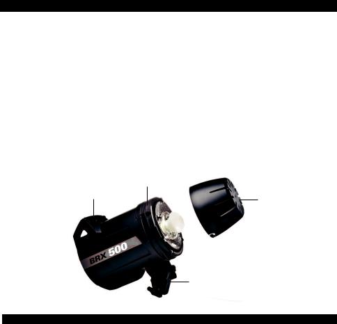
The BRX (Multivoltage) units are adapted for operation on 90 - 260V/50 - 60Hz. Before connecting for the first time, check to make sure that your Modelling Lamp coincides with the voltage. They must always be connected to an earthed ( grounded) mains supply. All BRX units have a bayonet mount and locking ring fitting, for fixing all Elinchrom and Prolinca accessories.
Mount the unit securely to a suitable stand or support.
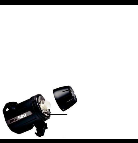
Remove the black protective cover. DO NOT operate the unit without first removing the black protective cover.
Operating instructions
1.Check that the modelling lamp voltage is correct.
2.Check that the mains switch (2) is in the OFF ("O" position).
3.Insert the mains cable into the MAINS INLET (1) and connect this to a FULLY EARTHED OUTLET 4.Using the mains SWITCH (2), switch the unit ON ("I" position).
5.Connect the synchro cord using the socket (5). 6.Select the power with the touch pad (10)
(A) Locking ring
Handle
(B) Protective cover (26124)
(C) Tilthead with locking umbrella holder
Switch and fuse
Mains supply
Use only the Elinchrom mains cord. Switch off the unit before the mains cord is connected to the mains plug.
Mains fuse
Standard type 5 x 20 mm, use only tempered fuse 8 AT (code 19022) for BRX.
Note: Before exchanging a blown fuse, switch off the unit and remove the mains cable. Open the little drawer in the mains plug with a screwdriver and replace the fuse with the spare fuse, which is placed in its support in this drawer. (N.B. Please don’t forget to check the correct rating of the fuse!).
Fuse for modelling light
Fast type 5 x 20mm, 2.5 AF
Switch off the unit and replace the blown fuse with a new one of the correct rating.
The fastblow fuse will protect the triac of the modelling lamp circuit, the lamp and therefore the flash tube.
7
Control panel |
English |
14
12 |
3 |
|
|
||
6 |
8 |
|
7 |
||
|
||
11 |
9 |
|
10 |
4 |
|
|
||
|
5 |
|
1 |
2 |
|
16 |
||
|
13
15
17
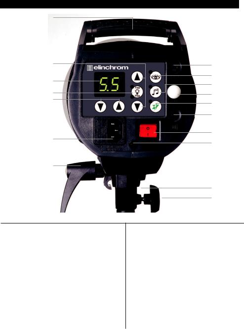
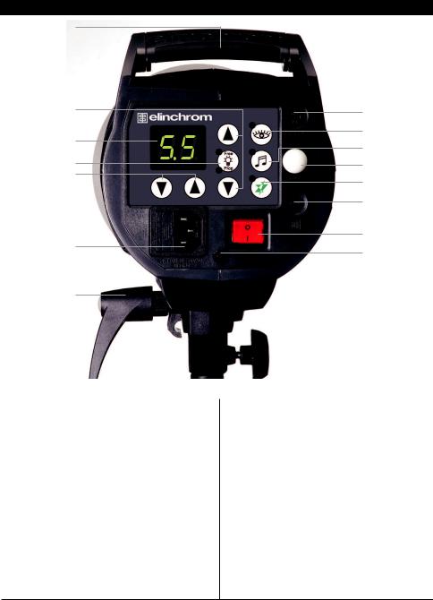
Overview of controls
1.Mains inlet socket includes the mains fuse (slow blow)
2.Mains on/off switch
3.Modelling lamp fuse
4.Open flash / Test button
5.Synch socket / 3.5 mm jack / low 5V sync voltage
6.Digital multi display and charge / discharge indicator*
7.Charge Ready Beep on/off – programmable*
8.Eye-Cell on/off – programmable*
9.Eye-Cell receptor
10.Power up & down buttons and scroll /pro gram buttons for advanced features setup*
11.Modelling lamp on/off-free-prop – programmable*
12.Modelling lamp up & down buttons and scroll /program buttons for advanced features setup*
13.Tilt head with extra umbrella fitting
14.Handle with support for spare fuses
15.Standard stand socket 5/8 inch
16.Centred umbrella tube for EL Umbrellas – 7 mm diameter
17.Knurled clamp screw
*The touches on this display are multifunctional to program / scroll the advanced features and to setup the integrated EL-Skyport Transceiver. For programming please read carefully the following pages!
8

Programmable features - Reset |
English |
How to „Reset“ the BRX
In case you need to „RESET“ the BRX to the manufacturer settings please follow the steps below:
1.Switch the unit “off“
2.Press both flash power up / down buttons (10) at the same time and switch the unit on
3.The Digital LED multi display (6) flashes in fast mode
4.Do not continue to press the touches, the resetting procedure is completed
Modelling lamp features & setup
Modelling lamps and fuses for 110 V & 230 V
Unit |
Modelling lamp 110V |
Modelling lamp 230V |
Socket |
Fuse |
BRX 250 |
100W krypton / 23006 |
100W krypton / 23002 |
E27 |
2.5AF / 19033 |
BRX 500 |
100W krypton / 23006 |
100W krypton / 23002 |
E27 |
2.5AF / 19033 |
Modelling lamp modes
>Setting: • Press “Free/Prop” button to set Modelling lamp ON to proportional mode or OFF
•Press “Modelling” up or down button to set Modelling lamp to free mode, press
“Free/Prop” to switch Modelling lamp OFF.
>LED Indication: • Prop-LED is ON: proportional Modelling lamp setting.
•Free-LED is ON: free Modelling lamp setting.
•Prop and Free-LED’s are OFF: Modelling lamp is inactive.
Setup Visual-Flash-Control (VFC) mode
> Enter VFC setup :
1. Press “Free/Prop” push button for more than 2 seconds, until the display shows “F.X” (“X” is 0 or 1) to enter into the Modelling lamp setup menu.
2. Use the “Flash-Power” up and down button to change setting:
-“F.0”: Visual-Flash-Control = OFF. Modelling lamp remains ON after flash.
-“F.1”: Visual-Flash-Control = ON. Modelling lamp switches off during recharging.
3.The display switches back to normal mode after approx. 4 seconds if no button is pressed. The settings are automatically stored.
4.Standard setting is “F.0”, VFC = OFF
Proportional modelling lamp setup (PMS)
(When using heads of different maximum power)
> Enter PMS setup:
1. Press “Free/Prop” button for more than 2 seconds to enter into the Modelling lamp setup menu. The display shows “F.X”, then press the “Free/Prop” button once more to the PMS menu, the display shows “-.X”
2. Use the “Flash-Power” up and down button to change the settings:
• “-.0”: PMS = OFF, Modelling lamp is set to maximum.
• “-.1”: PMS = -1 f-Stop, Modelling lamp is reduced by 1 f-stop.
9

Digital multi-display |
English |
The flash / modelling lamp power is displayed in f-stop compatible formats from 2.3 – 6.3 for BRX 500. The flash power difference from (e.g.) 5.3 – 6.3 is 1f-stop.
The power range is 5 f-stops variable in 1/10th intervals which can be customised to (e.g.) 5/10th etc.. During charging or discharging, the display «flashes». In case of overheating or malfunction, the display shows «ER» for error.
Display |
2.3 |
3.3 |
4.3 |
5.3 |
6.3 |
|
|
|
|
|
|
Joules / Ws |
31 |
62.5 |
125 |
250 |
500 |
Note: The «BRX 250 - BRX 500» units have an integrated discharge system, protected by a thermal switch. To avoid overheating, lower power settings of more than 2 f-stops by discharging manually with the «Test» touch button.
Sychronisation socket
Standard socket with 3.5 mm mini-jack (5).
N.B. Do not link ELINCHROM units by cable to other manufacturers sync. outlets. ELINCHROM uses the low voltage (5 V) for security reasons.
Open flash «test»
5
Sync
Having pressed the touch pad to release a flash, the green «READY» |
Test and Ready (4) |
light will appear again once the unit is recharged. If the green light does |
|
not appear the charge system could be defective. |
|
Please contact and send to an authorized Elinchrom service centre. |
|
Eye-Cell – advanced photocell sensor
The standard photocell can be remotely triggered by another flash unit! The BRX photocell is specially designed to work in studio light conditions
Direct light or other strong light sources may reduce the sensitivity of the cell.
10
Eye-CELL Setup |
English |
Intelligent Photocell-Sensor |
|
The Eye-Cell offers new features and can detect camera pre-flashes (anti red eye effect). To customise the pre-flash settings, please follow the instructions at paragraph 3.
Eye-Cell Functions
1.Standard Photocell mode
2.Eye-Cell pre-flash mode
3.Setup number of pre-flashes manually or set to automatic detection
4.Setup pre-flash timings! Only for advanced users!
1.Using the Standard Photocell Mode
Push “Cell” button, for less than 0.5 seconds to switch on/off the standard Photocell sensor.
LED Indication:
Cell LED is ON: Active photocell. Cell LED is OFF: Inactive photocell.
In “on” mode, the Photocell sensor will trigger the flash unit with any recognized flash impulse.
2. Eye-Cell Pre-Flash Mode
(This is only activation, not the setup. To Setup, follow step 3)
Press the Cell button for approx. 1 second; the status LED starts flashing.
LED Indication:
Cell LED flashes in slow intervals; the Eye-Cell pre-flash mode is activated. Cell LED is OFF; the Eye-Cell pre-flash mode is inactive.
Function:
In active mode the unit ignores up to 6 anti-red-eye flashes and synchronizes / triggers only with the last main flash. This is useful where the anti-red eye pre-flashes can’t be switched off.
3. Automatic Eye-Cell Pre-Flash Setup “c.0”
Press the Cell button for 4 seconds until display shows “c.X” for automatic setup. (“X” is the number of pre-flashes including main flash from 1 up to 7)
Scroll with the “Flash-Power” up and down button to “c.0”
Now use the camera-on flash and release a test exposure. The camera will release several anti-red eye flashes (if activated). The BRX Eye-Cell detects the number of flashes the camera released and stores the value automatically, and switches back to Eye-Cell Pre-flash mode. Ready to use.
! If the cell button was pressed down for 6 seconds the “Setup Pre-Flash Timeframe” is activated and the display shows t.4 or b.1 (standard settings). Do not change these values; this would deactivate the “Automatic Eye-Cell Mode”! Wait a few seconds, the unit switches back to the standard mode and the display shows the flash power settings. Should the t.4 or b.1 values have been changed, please set the “Setup Pre-Flash Timeframe” back to standard settings as descript at paragraph 4.
11

4. Manual Eye-Cell Pre-Flash Setup
A. Press Cell button approx. 4 seconds until display shows “c.X”.
(“X” is the number of settable pre-flashes plus the main flash from 1 up to 7)
B.With “Flash-Power” up and down button, set the number of pre-flashes incl. mainflash.
C.The display switches back to normal mode after approx. 4 seconds if no button is pressed. The settings are automatically stored.
D.Cell LED flashes in fast intervals if the Eye-Cell pre-flash mode is active.
> Recall The Eye-Cell Settings:
If you want to recall and control the actual Eye-Cell pre-flash setting, repeat the steps A to D.
5. Setup Pre-Flash Timeframe (only for advanced users)
Change manufacturer settings only in case of problems with the auto-detection
!of your camera pre-flashes.
>Setting:
•Press Cell button for more than 6 seconds until display shows “t.X” (“X” is the value from 1 to 8)
•Use the Cell button to toggle between “t.X” and “b.X” settings.
•Use the “Flash-Power” up and down buttons to change the values.
•The display switches back to normal mode after approx. 4 seconds if no button is pressed.
The settings are automatically stored.
•Standard settings are:
---> t.4 (t. is the time window of all released anti red-eye flashes incl. the main flash).
---> b.1 (b. is the minimum time delay between two anti red-eye flashes incl. the main flash).
Pre-Flash Timeframe Setting “t.X
t. is the time window of all released anti red-eye flashes incl. the mainflash. Change setting only when the pre-flash procedure is longer than the manufacturer settings.
Set the value t. between 1 and 8 to ensure that all pre-flashes including the main flash are inside the time frame.
Value t |
1 |
2 |
3 |
4 |
5 |
6 |
7 |
8 |
|
|
|
|
|
|
|
|
|
Time /seconds |
1 |
2 |
3 |
4 |
5 |
6 |
7 |
8 |
Pre-Flash Block Time Setting “b.X”: (Only For LED Anti Red-Eye Cameras)
Pre-Flash Block -Time: set the minimum delay between each pre-flash. Chose values between 0 and 7.
Value b |
0 |
1 |
2 |
3 |
4 |
5 |
6 |
7 |
|
|
|
|
|
|
|
|
|
Time: m/seconds |
0 |
2 |
4 |
6 |
8 |
10 |
12 |
14 |
12

Charge Ready Beep Features |
English |
This feature creates a melody if settings are different between each unit to improve the acoustical recognition that all the flashes have fired and recycled.
Charge Ready Beep Setup
•Setting
-Press “Audio” button, less than 0.5 seconds to switch the Charge Ready Beep (ON / OFF)
•LED Indication
-Charge Ready Beep LED is on: Audio is active
-Charge Ready Beep LED is off: Audio is inactive (Mute)
•Changing Charge Ready Beep -On-Time Setting
-Press Audio button for more than 2 seconds until the display shows “A.X” (“X” is the value from 1 up to 7)
-Use the Flash-Power” up and down button to change the value settings
-The display switches back to normal mode after approx. 4 seconds if no button was pressed. The settings are automatically stored.
-Standard setting is: “A.3”
Value A |
1 |
2 |
3 |
4 |
5 |
6 |
7 |
|
|
|
|
|
|
|
|
Beep-On-Time in m/seconds |
70 |
140 |
210 |
280 |
350 |
420 |
490 |
13

ELSkyport Transceiver For Wireless Triggering – Setup |
English |
The EL-Skyport on / off, Group, Frequency Channel and the Power Steps Per Push can be customised.
EL-Skyport on / off
Press the flash power up-down buttons together to enter into the “Advanced Feature Setup”
Display shows |
Change settings with the flash power up-down buttons |
r.0 |
EL-Skyport off |
r.1 |
ELSkyport on |
r.2 |
EL-Skyport speed mode (only available with EL-Skyport Speed) |
After 3 to 4 seconds the settings are saved automatically and the display shows the flash power setting.
Group Settings
Press the flash power up-down buttons together to enter into the “Advanced Feature Setup”. Then, scroll to G.1 using the Prop/Free button.
Display shows |
Select Group with the flash power up-down buttons |
G.1 |
Group 1 (standard setting) |
G.2 |
Group 2 |
G.3 |
Group 3 |
G.4 |
Group 4 |
After 3 to 4 seconds the settings are saved automatically and the display shows the flash power setting.
Frequency Channel Settings
Press the flash power up-down buttons together to enter into the “Advanced Feature Setup”. Then, scroll to F.1 using the Prop/Free button (only use in cases of interference with other systems).
Display shows |
Change the Channel with the flash power up-down buttons |
F.1 to F.8 |
Select Frequency Channel from 1 – 8. |
|
Note: The transmitter must have the same Frequency Channel |
|
setting. Standard setting is Frequency Channel 1. |
After 3 to 4 seconds the settings are saved automatically and the display shows the flash power setting.
Power Steps Per Push
Press the flash power up-down buttons together to enter into the “Advanced Feature Setup” Then, scroll to i.1 using the Prop/Free button.
Display shows |
Select values with the flash power up-down buttons |
|
i.0 |
+/- 1f-stop |
|
i.1 |
+/- |
1/10 (standard setting) |
i.2 |
+/- |
2/10 |
i.3 |
+/- |
3/10 |
i.4 |
+/- |
4/10 |
i.5 |
+/- |
5/10 |
After 3 to 4 seconds the settings are saved automatically and the display shows the flash power setting.
14
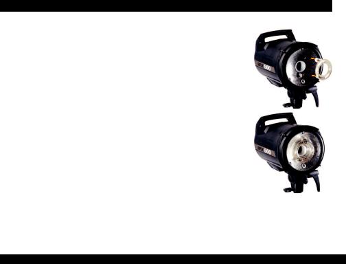
Flashtube replacement English
If the unit does not flash but the ON/OFF switch indicates that there is power, it could be that the flash tube needs replacing. Flash tubes have a long life with average use,
but multiflashing in long sequences can cause overheating of the electrodes leading to premature ageing, or perhaps the flastube is broken
or cracked
To replace the flash tube:
1. Switch off the mains switch
2.Remove the mains cable
3.Take the unit from its stand or lay it horizontally on a rigid surface. It will need to be held firmly whilst removing and replacing the tube.
4.Allow the flash tube and modelling lamp to cool for several minutes. They may be very hot.
5.Carefully remove and store the modelling lamp.
6.Use a protective glove to remove the flashtube:
A – Pull the flash tube firmly out of the terminals
B – If the tube is broken, use security gloves. Avoid cutting yourself!
C - If the tube is broken, never touch the metal electrodes and ensure that the unit is disconnected from the mains and discharged, wait min. 30 minutes! Use an insulated tool to pull out the electrodes.
7.Take the new flash tube. A glove or "plastic protection" MUST BE USED. Contact with your fingers on the glas, will cause dark markings on the tube when it is used.
8.Check that the tube is correctly aligned (central) and that the trigger contact is gripping the tube.
9.Re-connect and test the unit as usual.
Error Management
Error |
Fault |
|
Description |
|
E1 |
|
Overvoltage |
|
Switch unit OFF, wait 2 minutes and switch unit ON again. If the error shows |
|
|
|||
|
detected |
|
up again the unit requires a check up at the Elinchrom service centre |
|
|
|
|
|
|
E2 |
|
Overheating |
|
Wait until the unit has cooled down. The unit will switch back to normal opera- |
|
|
tion as soon as temperature decreases to normal working level. |
||
|
|
|
|
|
|
|
|
|
|
|
|
|
|
The Unit has detected a time out in the ADF mode. Switch the unit OFF, wait |
E3 |
|
Auto dump |
|
2 minutes and switch the unit ON again; use the Test release button for power |
|
|
function fault |
|
reduction. If the error shows up again the unit requires a check up at the Elin- |
|
|
|
|
chrom service centre. |
|
|
|
|
|
|
|
|
|
Unit has detected a time out during recharging. Switch unit OFF, wait |
E4 |
|
Charge fault |
|
2 minutes and switch unit ON again. If the error shows up again the unit |
|
|
|
|
requires a check up at the Elinchrom service centre. |
|
|
|
|
|
|
|
|
|
Unit has detected a mains supply fault. Check your mains cord and mains |
E5 |
|
Mains supply |
|
installation sockets. Switch unit OFF, wait 2 minutes and switch unit ON again. |
|
|
fault |
|
If the error shows up again the unit requires a check up at the Elinchrom |
|
|
|
|
service centre. |
|
|
|
|
|
|
|
Fan manage- |
|
Unit has detected a FAN management problem due to overheating. Wait until |
E8 |
|
|
the unit has cooled down. Check if the FAN is blocked. If the error shows up |
|
|
|
ment fault |
|
again the unit requires a check up at the Elinchrom service centre. |
|
|
|
|
|
|
|
|
|
|
15

Technical data |
|
BRX 250 |
BRX 500 |
Flash power |
J(Ws) |
250 |
500 |
Power supply |
V |
90/260 |
90/260 |
F-stop, 1m, 100 ISO, with reflector 48° |
|
64 |
90 |
Power range |
J(Ws) |
16-250 |
31-500 |
Variable flash power |
f-stops |
5 f-stops 1/16 - 1/1 |
|
Recycling time, min. / max. (230 V) |
s |
0.29 / 0.73 |
0.36 / 1.13 |
Recycling time, min. / max. (115 V) |
s |
0.27 / 1.02 |
0.34 / 1.45 |
Colour temperature max. power |
°K |
5360 |
5410 |
Flash duration (t 0,5) 1/1 |
s |
1/2762 |
1/1558 |
Flash duration (t 0,5) 1/2 |
s |
1/2165 |
1/1395 |
Voltage stabilisation |
|
± 0.5 % Maximum stability for digital imaging |
|
Sync voltage |
V |
5 V, maximum compatibility with digital cameras |
|
Plug-in flashtube |
Code |
24000 |
24000 |
Modelling lamp 230 V |
Code |
23002 |
23002 |
Modelling lamp 115 V |
Code |
23006 |
23006 |
Fan cooled |
|
Microprocessor controlled fan |
|
EL-Skyport |
|
Integrated transceiver, 4 Groups, 8 Frequencies |
|
Dimensions |
cm |
|
26 x 19 x 14 |
Weight |
kg |
1.85 |
2.05 |
BRX |
Code |
20440.1 |
20441.1 |
Radio interference suppressiv |
CE-IEC 491 EN 60 555 - EN 61 000 - 4 - 2/3/4/5 |
||
Tolerances and specifications conforming to IEC and CE standards. Technical data subject to change without notice.
16

English
Transmitter Speed
19350
User Manual
Contents :
Features |
|
18 |
||
Battery Installation |
|
18 |
||
Hot-shoe connector |
|
18 |
||
Operating Instructions |
|
18 |
||
Frequency Channel |
|
19 |
||
Trigger Modes |
|
19 |
||
Integrated SYNC Socket |
|
20 |
||
Elinchrom RX Features |
|
20 |
||
EL-Skyport Modules |
|
21 |
||
Troubleshooting |
21 |
|||
CE Statements |
|
|
|
22 |
FCC Compliance and |
|
|
|
|
Advisory Statement |
|
22 |
||
Disposal and recycling |
22 |
|||
|
|
|
|
|
|
|
|
|
|
17

English
EL-Skyport Transmitter SPEED //19350 Operating instructions :
2.4 GHz digital wireless Flash Trigger Transmitter
Features
EL-Skyport Transmitter Speed is designed with the latest 2.4 GHz Digital Wireless Technology.
• SLR Camera Sync speeds: SPEED mode up to |
• Status LED for EL-Skyport mode and battery |
1/250 s, STANDARD mode 1/160 - 1/200 s. |
status. |
• 5 selectable trigger modes, (4 Groups + All) |
• Improved housing, battery drawer and |
• 8 frequency channels. |
switches. |
• 40 Bit security encryption. |
• New Hot-shoe with screw-lock. |
• Up to 60 m range indoors for standard mode and |
• New extra features; conigure EL-Skyport with |
up to 40 m in speed mode. |
the new EL-Skyport PC / MAC software 3.0. |
• Up to 120 m range outdoors for standard mode |
You will appreciate the convenience of this |
and up to 60 m in speed mode. |
•Battery life up to 6 Months - over 30’000 lashes. professional and powerful wireless device.
•RX-feature buttons (Remote Control).
•Test trigger button and feature button.
•Integrated Hot-shoe (middle contact) improved.
•SYNC-socket for direct connection improved.
•Two lash modes, standard and speed.
•The “Standard” mode is fully compatible with previous EL-Skyport versions.
•The SPEED function is available for Ranger
Quadra AS, BXRi 250 / 500 und D-Lite it and all other units, when used with the Universal Speed.
Battery Installation
Note: Shutter speed and distance range are inluenced by interference from other 2.4 GHz electronic equipment and relections of ceilings, walls, loors, furniture, metall, trees and humidiy in woods etc.
For better performance the Transmitter and Receiver antenna should have direct sight, without any walls or objects in - between.
1.Pull the battery drawer out carefully.
2.Place the Lithium battery, see Fig. 1 for correct polarity.
3.Close the battery drawer.
!CAUTION:
•Ensure correct polarity / minus pole on top.
•Use only the Lithium Battery CR2430 3.0 V 19372.
•Remove battery if the EL-Skyport Transmitter is not used for some time.
•Never short-circuit battery poles.
•Avoid direct sunlight or temperatures above 45°C. The battery may explode!
Hot-Shoe Connector with Screw-Lock
The new Hot-shoe connector with screw-lock and middle contact synchronisation is designed to it digi- tal and analogue cameras with maximum sync output of 3 V (the middle contact is the positive pole).
Operating Instructions |
Battery (19372) |
|
|
|
|
Fig. 1 |
Minus pole on top |
|
|
Flexible swivel |
|
Battery drawer |
|
|
|
Antenna 360 ̊ |
|
|
|
|
|
|
|
|
|
|
|
|
Hot-shoe with |
|
|
|
|
|
screw lock and |
|
|
|
|
|
SYNC socket |
|
|
|
|
|
|
18
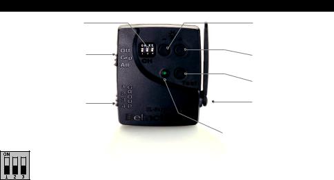
|
|
English |
Fig. 2 |
Frequency |
RX feature button |
|
channel selector |
Power decrease |
|
|
RX feature button |
|
MODE switch |
Power increase |
|
or modelling lamp |
|
|
|
|
|
|
toggle |
|
|
Flash Test / Flash Mode / |
|
|
Coniguration button |
|
GROUP switch |
Flexible swivel |
|
Antenna 360 ̊ |
|
|
|
Status LED |
Frequency Channel
Note:
Transmitter and the corresponding Transceiver RX, the Universal Receiver or the EL units with integrated EL-Skyport Receiver must have the same frequency channel settings!
Frequency |
|
Slide Button coniguration |
|
Frequency |
||
Channel |
|
|
|
|
|
/ Mhz |
1 |
|
2 |
|
3 |
||
|
|
|
|
|
|
|
1 (default) |
Off |
|
Off |
|
Off |
2456 |
2 |
On |
|
Off |
|
Off |
2458 |
|
|
|
|
|
|
|
3 |
Off |
|
On |
|
Off |
2460 |
4 |
On |
|
On |
|
Off |
2462 |
5 |
Off |
|
Off |
|
On |
2469 |
|
|
|
|
|
|
|
6 |
On |
|
Off |
|
On |
2471 |
7 |
Off |
|
On |
|
On |
2473 |
8 |
On |
|
On |
|
On |
2475 |
EL-Skyport Sync Speed & Standard Mode
The SPEED function is available for Ranger Quadra AS, BXRi 250 / 500 und D-Lite it and all other units, when used with the EL-Skyport Universal Speed.
Select “Speed” sync mode
Synchronises SLR cameras up to 1/250 s, or compact digital cameras up to 1/2850 s
-Select “Group” or “All” mode.
-Press test push button for minimum 5 seconds until the STATUS LED lashes two times.
-Release test push button.
-Now the EL-Skyport Transmitter Speed works in “SPEED” mode (r.2 mode).
Select “Standard” triggering mode
Synchronises SLR cameras up to 1/200 s, or compact digital cameras up to 1/1600 s
-Select “Group” or “All” mode.
-Press test push button for minimum 5 seconds until the STATUS LED lashes one time.
-Release test push button.
-Now the EL-Skyport Transmitter Speed works in “STANDARD” mode.
EL-Skyport Module Coniguration:
Only possible with EL-Skyport PC / MAC software v 3.0 and higher.
-Power-Save Timer, individual programmable or disabled.
-Trigger delay is programmable from 250 ms up to 15 s.
-Download the FREE EL-Skyport Software from www.elinchrom.com
19

English
SET Conig Mode: (to conigure included features)
- Switch module OFF.
- Hold test push button and switch TX ON.
- Keep test push button pressed until STATUS LED is ON.
Check also EL-Skyport PC / MAC software 3.0 for changing Transmitter Speed setting.
1.Off Unit is OFF, no function.
2.Select Group - Group (1 to 4).
Set switch to Group. and select Group 1 to 4.
All corresponding EL-Skyport Receivers with the same selected Group (1 to 4) are triggered.
3.ALL Mode switch is set to ALL.
All corresponding EL-Skyport Receivers are triggered regardless of which Group is selected.The EL-Skyport Transmitter triggers the EL-Skyport Receiver modules in the following modes:
Integrated Hot-Shoe SYNC 2.5 mm Socket
Use the included Sync cable to connect the integrated 2.5 mm Mono Jack socket with the camera or lens PC socket directly.
EL-Skyport Transmitter SPEED RX Features
Compatible with Ranger RX, Style RX, Digital RX, BXRi 250 / 500, Ranger Quadra AS!
If the EL-Skyport Transmitter SPEED is used with the EL-Skyport Transceiver RX, BXRi 250 / 500 or the Ranger Quadra AS, the following EXTRA
features are available:
Depending upon which Group is selected, the following RX-unit settings can be modiied:
1. Flash power increase in 1/10 f-stops.
press push button + to increase the power of selected Group of (or ALL) RX-units in 1/10 f- stops.
press push button - to reduce the power of selected Group of (or ALL) RX-units in 1/10 f-stops.
3.Modelling lamp toggle.
press and hold the push button +, 2 seconds or longer before releasing,2. Flash power decrease in 1/10 f-stops.
to toggle modelling lamp of the selected Group of (or ALL) RX-units.
Power save mode timer:
-After not using the Transmitter for 30 minutes the Power Save mode is active. To reactivate the
Transmitter, press the TEST push button.
-The Power Save mode timer can be conigured with the EL-Skyport PC / MAC software v 3.0 and
higher.
Status LED:
-LED lashes every 4 seconds one time in “Standard” mode and two times in “Speed” mode.
-LED intensity correspond to the battery status - if off or very low => exchange the battery.
-LED is OFF if the Transmitter is switched OFF or in Power Save mode.
.
Reset to manufacturer default setting:
-Switch ON.
-Press test button for min 10 seconds.
20
English
EL-Skyport Modules
EL-Skyport Universal SPEED (NEW) / Universal (previous version)
• Universal Receiver for all makes of Flash with a SYNC socket, conforming to Sync norms!
EL-Skyport Transceiver RX
•This Transceiver is only for Elinchrom RX units. The module operates all RX features with the EL-Skyport software and triggers the lash.
EL-Skyport USB RX SPEED (NEW) / USB RX (previous version)
•To operate RX lash units via computer the USB module should be used in conjunction with the EL-Skyport Transceiver RX and the EL-Skyport software.
Universal Speed |
Transceiver RX |
USB RX Speed |
& Universal |
19353 |
& USB RX |
|
Troubleshooting
Should an error occur, irst check the following points:
Having this problem? |
Check the following points: |
|
|
|
|
No lash unit can be triggered |
Check if the Transmitter is switched ON. |
|
with the Transmitter |
|
Check battery polarity. |
Mode “All” is selected |
|
Check if the Receiver module is connected correctly to the unit. |
|
|
Check if the frequency selector switch is set to the same channel. |
|
|
Check if Transmitter is in the same trigger mode Speed or Standard. |
Some units do not ire when |
Check if the Channel selector switch is set to the same Group. |
|
triggered with the Transmitter |
|
Reduce distance to any “not working” unit. |
Mode “Grp” is selected |
|
Check if Transmitter is in the same trigger mode Speed / Standard. |
TEST lash works, but the camera |
Check hot-shoe itting. |
|
will not trigger lash unit |
|
Connect the 2.5 mm to PC SYNC cable instead of hot-shoe connection. |
Limited Distance range |
Reposition the units. |
|
|
|
Increase the distance to walls and ceilings. |
|
|
Position the antenna of Transmitter and Receiver. |
|
|
Use an RX extension cable to reduce the distance between the modules. |
21

English
CE Statements
This device has been tested and found to comply with the requirements set
up in the council directive on the approximation of the law of member states relating to EMC Directive 89/336/EEC, Low Voltage Directive 73/23/EEC and R&TTE Directive
99/5/EC
FCC Compliance and Advisory Statement
This device complies with Part 15 of the FCC rules. Operation is subject of the following two condi- tions: 1. this device may not cause harmful interference, and 2. this device must accept any interfer- ence received, including interferences that may cause undesired operation.
The equipment has been certiied to comply with the limits for a Class B computing device pursuant to Part 15 of the FCC Rules. These limits are designed to provide reasonable protection against harm- ful interference in a residential installation. This equipment generates, uses, and can radiate radio frequency energy and, if not installed or used in accordance with the instructions, may cause harmful interference to radio communications. However, there is no guarantee that interference will not occur in a particular installation. If this equipment does cause harmful interference to radio or television re- ception, which can be determined by switching the equipment off and on. The user can try to correct the interference by the following measures:
1.Reorient or relocate the receiving antenna
2.Increase the separation between the equipment and receiver
3.Connect the equipment to an outlet on a circuit different from that to which the receiver is con-
nected.
4.Consult the dealer or an experienced radio/TV technician for help, changes or modiication not expressly approved by the party responsible for compliance could avoid the user’s authority to operate the equipment.
Disposal and recycling
Thisdevicehasbeenmanufacturedtothehighestpossibledegreefrommaterialswhich canberecycledordisposedofinamannerthatisnotenvironmentally damaging. The
device may be taken back after use to be recycled, provided that it is returned in a condi-
tion that is the result of normal use. Any components not reclaimed will be disposed of in
an environmentally acceptable manner.
If you have any question on disposal, please contact your local ofice or your local ELINCHROM agent (check our website for a list of all ELINCRHOM agents worldwide).
22

Inhalt |
Deutsch |
Einleitung |
24 |
CE Konformitätserklärung / Entsorgung |
25 |
Sicherheitsund Gebrauchshinweise |
26 |
Grundfunktionen & Intelligente programmierbare Funktionen |
27 |
Vor dem Start / Ein-Ausschalten & Sicherungen |
28 |
Bedienteil & Multi-Display |
29 |
Zusätzliche programmierbare Sonderfunktionen - Reset |
30 |
Einstelllampe (Pilotlampe) Funktionen und Setup |
30 |
Digitales Multi-Display |
31 |
Photozelle / Eye-Cell / Automatische Einstellung |
32 |
Photozelle / Eye-Cell / Manuelle Einstellungen |
33 |
Akustische Ladebereitschaft – Funktionen & Setup |
34 |
Blitzauslösung – Integrierter EL-Skyport Empfänger Funktionen & Setup |
38 |
Blitzröhrenwechsel - Fehlerbehebung |
36 |
Technische Daten |
37 |
EL-Skyport Transmitter Speed Betriebsanleitung |
38-43 |
Garantie |
128-130 |
VERMERK: Toleranzen der technischen Daten für Bauelemente und Messwerte entsprechen den IEC und EC Normen. Technische Änderungen vorbehalten. Die Werte können durch Bauelementetoleranzen schwanken und sind als Richtwerte zu verstehen und nicht im rechtlichen Sinne als zugesicherte Eigenschaften. Keine Haftung für Druckfehler.
23

Einführung |
Deutsch |
Die hervorragende Lichtqualität und die technische Leistung der BRX Kompaktblitzanlagen beruhen auf einer 45 jährigen Erfahrung auf dem Gebiet der Blitzelektronik und der
Herstellung von Blitzanlagen. Elinchrom Blitzlichtprodukte entsprechen den gültigen elektrischen Normen.
BRX 250 / BRX 500 Compact Flash
BRX Kompaktblitzanlagen wurden von Elinchrom S.A. LTD. / Schweiz entwickelt.
ELINCHROM verwendet für seine Produkte nur hochwertige und geprüfte Baukomponenten.
Die Endkontrolle sichert die Einhaltung des Qualitätsstandards und garantiert eine einwandfreie Funktion. Wir hoffen, dass Sie mit diesem Gerät vollkommen zufrieden sind. Um einwandfreie ErgebnissezubekommenunddiezuverlässigeFunktionfürlangeZeitzusichern,sindnachstehende
Gebrauchsanweisungen und Vorsichtsmassnahmen zu befolgen.
FCC Class B Compliance Statement / USA
This equipement has been tested and found to comply with the limits for a class B digital device, pursuant to Part 15 of the FCC Rules and meets all requirements of the Canadian Interference-Causing Equipement Regulations. These limits are designed to provide reasonable protection against harmful interference in a residential installation. This equipement generates, uses, and can radiate radio frequency energy and, if not installed and used in accordance with the instruction manual, may cause harmful interference to radio communications. However, there is no guarantee that interference will not occur in a particular installation. If this equipement does not cause harmful interferences to radio or television reception, which can be determined by turning the equipement off and on, the user is encouraged to correct the interferences by one or more of the following measures:
•Reorient or relocate the receiving antenna.
•Increase the separation between the equipement and receiver.
•Connect the equipement into an outlet on a circuit different from that to which the receiver is connected.
•Consult the dealer or an experienced radio/TV technician for help.
ELINCHROM S.A. LTD. is not responsible for any radio or television interference caused by unauthorised modifications of this equipement or the substitution or attachment of connecting cables and equipement other than those specified by ELINCHROM S.A. LTD. The correction of interference caused by such unauthorised modification, substitution or attachment will be the responsibility of the user.
24
Konformitätserklärung |
Deutsch |
Dieses Gerät entspricht Paragraph 15 der FCC Normen, die folgende Punkte beinhalten:
1.Dieses Gerät verursacht keine Interferenzen die nicht den Normen entsprechen.
2.Dieses Gerät akzeptiert jegliche Interferenzen, auch die, die eventuell Störungen
verursachen können.
Produktbeschreibung; |
BRX 250 / BRX 500 |
|
|
Marktname: |
ELINCHROM |
|
|
Modelle: |
20440.1 / 20441.1 |
|
|
Verantwortliche Firma: |
Elinchrom LTD |
|
Av. De Longemalle 11 |
|
1020 Renens / Switzerland |
|
|
Phone : |
+41 21 637 26 77 |
|
|
Fax: |
+41 21 637 26 81 |
|
|
ELINCHROM S.A. LTD., erklärt mit ihrem Marktnamen, dass die Geräte mit den genannten Modellnamen nach den einschlägigen EWG, DIN, IEC und FCC Normen geprüft und getestet wurden und allen Vorschriften entsprechen. Alle notwendigen Prüfungen wurden durchgeführt um die Einhaltung und Sicherheit auch während der Serienproduktion
Entsorgung and Recycling
Dieses Gerät wurde weitestgehend aus Materialien hergestellt, die umweltschonend entsorgt und einem fachgerechten Recycling zugeführt werden können. Nach seinem
Gebrauch wird das Gerät zurückgenommen, um es einer Wiederverwendung bzw. werkstofflichen Verwertung zuzuführen, soweit es in einem Zustand zurückgegeben
wird, der dem bestimmungsgemäßen Gebrauch entspricht. Nicht verwertbare Geräteteile werden sachgemäß entsorgt. Bei Fragen zur Entsorgung wenden Sie sich bitte and Ihre Verkaufsstelle. Eine Liste aller Verkaufsstellen in Ihrer Nähe inden Sie auf unserer Homepage www.elinchrom.com.
CE Zertifizierung
Dieses Studioblitzgerät entspricht den Anforderungen der EWG Richtlinie 89/336/ EWG Elektromagnetische Verträglichkeit” und 73/23/EWG “
Niederspannungsrichtlinie”.
CE Kennzeichnung für EL-Skyport
Dieses Gerät erfüllt in der ausgelieferten Ausführung die Anforderungen der EG Richtlinie 89/336/EWG „Elektromagnetische Verträglichkeit“ und 73/23/EWG “Niederspannungsrichtlinie” und die Richtlinie nach R&TTE 99/5/EC.
Zeichenerklärung
In diesem Handbuch werden folgende Darstellungsmittel verwendet.
Kennzeichnet Hinweise, bei deren Nichtbeachtung Ihre Gesundheit, die Funktions fähigkeit Ihres Gerätes oder die Sicherheit Ihrer Daten gefährdet sind.
!kennzeichnen Kapitelnamen und Begriffe, die hervorgehoben werden sollen. Kursive Schrift kennzeichnet Bedienelemente, Baugruppen oder Menüpunkte.Kennzeichnet zusätzliche Informationen bzw. Tipps. “Anführungszeichen”
25

Sicherheitsvorschriften |
Deutsch |
DieseselektronischeBlitzgerätsolltenichtimFreien,beiunzureichenderStromzuführung,auchnicht in einem feuchten oder staubigen Umfeld eingesetzt werden; achten Sie ebenfalls darauf, dass die Luft nicht mit Fremdgasen angereichert ist. Die elektrische Steckdose muss den Normen entsprechen und geerdet sein.
•Blitzanlagen nur mit Genehmigung der Zuständigen, in Krankenhäusern, Museen, Fabriken,
Wissenschaftlichen Instituten , etc. verwenden.
•Dieses Gerät nicht in verbotenen oder explosiven Bereichen verwenden.
•Lassen Sie niemals Kinder unbeaufsichtigt mit Blitzanlagen allein!!
•Nur originales Elinchrom Zubehör verwenden.
Blitzröhren und Pilotlicht
•Blitzröhren und Pilotlicht werden bei Gebrauch sehr heiß.
•Sie dürfen nicht in der Nähe von brennund entlammbarem Material benutzt oder
unmittelbar nach der Benutzung dort aufbewahrt werden.
•Schauen Sie niemals direkt in das Blitzlicht!
•Das Blitzgerät muss vom Stromnetz getrennt werden, abkühlen, bevor eine
Sicherung / Halogenlampe / Blitzröhre gewechselt wird.
•Die Wartezeit beträgt mindestens 30 Minuten.
•Niemals Blitze aus geringem Abstand auf Personen auslösen. Der Mindestabstand sollte
1- 2 m betragen, abhängig von der eingestellten Blitzleistung.
•Grundsätzlich Abstand zu anderen elektronischen Geräten halten die in Funktion sind.
Transport
•Transportieren Sie Ihre Blitzgeräte vorsichtig und nur in der Originalverpackung oder einer anderen geeigneten Verpackung, die Schutz gegen Stoß und Schlag gewährt.
•Vermeiden Sie Kondensationsprobleme durch starke Temperaturschwankungen.
•Der Transport darf nur im völlig entladenen Zustand erfolgen. Warten Sie vor dem Transport des Gerätes mindestens 30 Minuten nach der Trennung der Versorgungsspannung.
•Lassen Sie niemals Ihr Gerät fallen (Das Blitzröhrenglas kann brechen).
Netzleitung
Um die Betriebssicherheit des Gerätes zu gewährleisten, benutzen Sie nur originale
Netzkabel.
•Die Netzleitung muss HARoder VDEZertiizierung aufweisen. Die Markierung HAR oder VDE ist am Gerätestecker bzw. – Buchse aufgedruckt.
•Die Strombelastbarkeit muss dem Gerät entsprechen.
•Verwenden Sie keine Mehrfachsteckdosen um mehr als ein Gerät zu betreiben.
•Blitzgeräte speichern elektrische Energie in Kondensatoren mit hoher
Spannung.
•Kondensatoren können explodieren während das Gerät benutzt wird.
!• Niemals defekte Blitzgeräte einschalten.
•Das öffnen, modiizieren und reparieren der Blitzanlagen ist verboten.
•Nur von Elinchrom autorisierte Werkstätten dürfen Reparaturen vornehmen.
•Schalten Sie wegen der hohen elektrischen Spannung an den Kontakten das Blitzgerät nicht ein, ohne dass Kameraleuchte oder Blitzröhre angebracht
sind! Lebensgefahr!
26

Grundfunktionen |
Deutsch |
Die Grundfunktionen sind einfach zu bedienen und sind ähnlich zu vorherigen Elinchrom Blitzgeräten.
•Blitzleistungseinstellung mit „auf & ab“ Pfeiltasten
•Einstelllichtleistungseinstellung mit „auf & ab“ Pfeiltasten
•Einstelllichtfunktionen: proportional / frei / aus
•Photozelle ein / aus
•Akustische Ladebereitschaft ein / aus
•Testblitz
•Synchronisierungsbuchse für 3.5 mm
•Integrierter EL-Skyport Empfänger zur Blitzlichtauslösung und Fernbedienung
Zusätzliche programmierbare Sonderfunktionen
Alle neuen Funktionen können individuell programmiert werden.
Lesen Sie dazu aufmerksam wie die Funktionen konfiguriert werden!
VFC (Visual-Flash-Control) Visuelle Blitzkontrolle
Als zusätzliche oder alternative Abblitzkontrolle schaltet sich das Einstelllicht während der
Wiederaufladung ab, wenn diese Funktion aktiviert wurde.
Proportionale Einstelllichtanpassung
Wenn z.B. BRX Blitzgeräte mit 250 und 500 J / Ws eingesetzt werden kann das Einstelllicht beim BRX 250 um 1 Blende herabgesetzt werden um eine bessere visuelle Kontrolle zu ermöglichen.
Eye-Cell automatische & manuelle Einstellung zur Erkennung von Vorblitzen
Einige Kameras mit integriertem Blitz lösen Vorblitze aus um rote Augen zu vermeiden. Normalerweise lösen BRX Studioblitzgeräte bereits beim ersten Blitzimpuls aus was in diesem Fall eine Fehlsynchronisierung verursacht. Die Eye-Cell Photozelle kann so programmiert werden das, dass Gerät erst nach dem letzten Hauptblitz synchronisiert (bis max. 6 Vorblitze)
Akustisches Bereitschaftssignal / Anpassung der Tonlänge
Die Tonlänge des Bereitschaftssignals kann individuell angepasst werden zur besseren Identiizierung der auslösenden Blitzgeräte.
EL-Skyport Blitzauslösung & Fernbedienung
Der integrierte El-Skyport Empfänger kann zur Blitzsynchronisierung mit Gruppen- & Kanalwahl, Einstellung der Blitzleistung oder zum Abschalten des Einstelllichtes verwendet werden. Dazu wird der optionale El-Skyport Transmitter / Sender benötigt.
Blitzund Einstelllicht / Individuelle Anpassung der Leistungseinstellung
Normalerweise wird die Blitzund Einstelllichtleistung schrittweise mit dem Leistungstaster in 1/10 Blendenstufen eingestellt. Diese Stufen können von 1/10 – 7/10 oder auf eine Blende umprogrammiert werden.
Temperaturgesteuertes Kühlgebläse
Der interne Mikroprozessor kontrolliert die Gerätetemperatur. Wird es zu warm schaltet sich das Kühlgebläse automatisch ein, bis die korrekte Betriebstemperatur erreicht wurde. Ist das Kühlgebläse blockiert oder defekt erscheint die Fehlermeldung E8 auf dem Display.
27
Vor dem Start |
Deutsch |
Das BRX Blitzgerät ist mit einer Multivoltage-Technologie ausgestattet und kann mit 90V -260V /50-60 Hz
Stromnetzen verwendet werden. Lediglich der Einstelllampenwert muss dem jeweiligen Stromnetz entsprechen. Das Stromnetz muss geerdet sein. Dieses Gerät ist mit einem speziellen verschließbaren Bajonettring ausgestattet - wie alle anderen Kompaktgeräte und Blitzköpfe des Systems. Das Relektorenprogramm ist voll kompatibel. Setzen Sie das Kompaktgerät auf ein Lampenstativ. Entfernen Sie die Schutzkappe, indem
Sie den Verriegelungsring (A) nach links drehen, die Schutzkappe ebenfalls nach links drehen (B) und nach vorn entnehmen. Reflektoren werden in umgekehrter Reihenfolge adaptiert.
Achtung: Wechselbare Blitzröhren müssen korrekt und fest in der Steckhalterung sitzen bevor das Blitzgerät eingeschaltet wird. Die Blitzröhre nur mit Schutzhandschuhen berühren, bzw. wechseln! Die Halogenlampe darf beim Einsetzen nicht mit den Fingern berührt werden (Plastikschutzhülle dazu benutzen).
Inbetriebnahme
1.Überprüfen Sie, dass die Netzanschluss-Steckdose geerdet ist und die Stromspannung mit der des Blitzgerätes / Einstelllampe übereinstimmt.
2.Der Netzschalter muss auf AUS stehen.
3.Netzkabel am Gerät einstecken und dann erst mit dem Stromnetz verbinden.
4.Das Gerät mit dem Kippschalter / Netzschalter einschalten.
5.Synchronkabel an die Synchronbuchse anschließen.
6.Blitzleistung mit den Leistungstasten wählen.
Bajonettverriegelungsring (A)
Haltegriff |
|
|
Schutzkappe (B) |
|
|
|
|||
|
|
|
||
|
|
|
|
|
|
|
|
|
|
|
|
|
|
|
Zentrierte Schirmhalterung (C)
Netzanschluss & Sicherungen
Netzanschluss
Nur das originale Elinchrom Netzkabel verwenden. Der Kompaktblitz wird mit Strom versorgt, wenn der Netzschalter eingeschaltet ist. Diesen Schalter immer erst ausschalten, bevor das Netzkabel gezogen wird.
Netzsicherung
Nur Sicherungen des Typs 5 x 20 mm 8 AT (träge) verwenden.
Bevor eine defekte Sicherung gewechselt wird, das Gerät abschalten und das Netzkabel entfernen.
Öffnen Sie die kleine Sicherungsschublade am Netzeingangschalter mit einem Schraubendreher und wechseln Sie die Sicherung mit der in der Schublade befindlichen Reservesicherung aus.
Einstelllichtsicherung
Nur Sicherungen des Typs 5 x 20 mm 2.5 AF (flink) verwenden.
Bevor eine defekte Sicherung gewechselt wird, das Gerät abschalten und das Netzkabel entfernen. Die flinke Sicherung schützt die Einstelllichtelektronik und die Halogenlampe vor
Explosionen und damit auch die Blitzröhre vor Beschädigungen.
28
Bedienteil |
Deutsch |
14
12 |
3 |
|
|
||
6 |
8 |
|
7 |
||
|
||
11 |
9 |
|
10 |
4 |
|
|
||
|
5 |
|
1 |
2 |
|
16 |
||
|
13
|
|
|
|
|
|
15 |
|
|
|
|
|
|
|
||
Kontrollelemente |
|
|
|
|
17 |
||
|
|
|
|||||
|
|
|
|
|
|
||
|
|
|
|
|
|
|
|
1. |
Netzeingang mit Sicherungsschublade |
11. |
Einstelllicht, individuell – proportional - |
||||
2. |
Hauptschalter ein / aus |
|
|
aus, programmierbar* |
|||
3. |
Einstelllichtsicherung (flinke Sicherung) |
12. |
Einstelllicht, Leistungsverstellung & |
||||
4. |
Testblitz |
|
|
Programmiertasten* |
|||
5. |
Synchroneingang 5V (für 3,5 mm |
13. |
Feststellgriff für Neigefunktion und |
||||
|
Klinkenstecker) |
|
|
zusätzliche Schirmhalterung |
|||
6. |
Digitale Multianzeige für Blitzleistung & |
14. |
Haltegriff mit Ersatzsicherungshalter |
||||
|
andere Funktionen* |
15. |
Standard 5/8“ Stativhülse |
||||
7. |
Bereitschaftssignal, programmierbar* |
16. |
Selbstklemmende, zentrierte |
||||
8. |
Photozelle / Eye-Cell, programmierbar* |
|
|
Schirmhalterung Ø 7 mm |
|||
9. |
Empfangselement Fotozelle |
17. |
Stativ-Feststellschraube |
||||
10.Leistungseinstellung Blitz / Einstelllicht & Programmiertasten*
*Diese Taster sind multifunktional zum programmieren und aufrufen der Menüfunktionen und zum einstellen der EL-Skyport Funktionen. Lesen Sie aufmerksam auf den nächsten Seiten, wie die Zusatzfunktionen programmiert werden können.
29

Zusätzliche programmierbare Sonderfunktionen - Reset |
Deutsch |
Das BRX auf Herstellerkonfiguration zurücksetzten
Falls das Gerät auf die Herstellerwerte zurückgesetzt werden soll bitte folgende Schritte ausführen:
1.Gerät abschalten
2.Die Blitzleistungseinstellungstaster (10) gleichzeitig drücken und das Gerät einschalten
3.Die LED Anzeige blinkt im schnellen Modus
4.Die Taster nicht mehr drücken, das BRX wurde zurückgesetzt
Einstelllichtfunktionen und Setup
Einstelllicht - Tabelle für 110 V & 230 V
Blitzgerät |
Einstelllicht 110V |
Einstelllicht 230V |
Fassung |
Sicherung |
BRX 250 |
100W Krypton / 23006 |
100W Krypton / 23002 |
E27 |
2.5AF / 19033 |
BRX 500 |
100W Krypton / 23006 |
100W Krypton / 23002 |
E27 |
2.5AF / 19033 |
Einstelllicht Setup
Einstellung Free / Prop / Aus
1. Mit dem „Free / Prop“ Taster die Funktionen Einstelllicht Ein / Proportional / Aus auswählen.
2. Mit dem „Einstelllicht Auf /Ab“ Taster die Funktion „Free“ aktivieren und die Leistung einstellen.
3.Mit dem „Free / Prop“ Taster dass Einstelllicht ausschalten.
4.Die aufleuchtende LED zeigt die jeweilige Funktion an.
Einstellung Visual-Flash-Control (VFC) Optische Abblitzkontrolle
(Das Einstelllicht erlischt nach dem abblitzen und schaltet sich nach dem Ladevorgang ein)
1. Den “Free / Prop“ Taster min. 2 Sekunden drücken bis im Display F.X anzeigt wird. 2. Mit dem “Blitzleistung Auf /Ab“ Taster die Funktion VFC ein- / ausschalten.
3.“F.0“ VFC ist deaktiviert. Das Einstelllicht schaltet sich nach dem blitzen nicht ab.
4.“F.1“VFC ist aktiviert. Das Einstelllicht schaltet sich während der Wiederauladung ab!
Wird kein Taster gedrückt, zeigt das Display nach 4 Sekunden wieder die eingestellte Blitzleistung an. Die gewählte Einstellung wird automatisch gespeichert. Bei der Werkseinstellung ist die VFC Funktion deaktiviert.
Proportionale Einstelllichtanpassung (PMS)
(Bei Verwendung von Blitzgeräten mit unterschiedlicher Blitzleistung, 250 J und 500 J)
1.Den “Free / Prop“ Taster min. 2 Sekunden drücken bis im Display F.X anzeigt wird.
2.Sofort den “Free / Prop“ Taster nochmals kurz drücken, das Display zeigt “-.X“ an.
3.“-.0“ PMS ist deaktiviert.
4.“-.1“ Das Einstelllicht wird um eine Blende reduziert (Das entspricht dem Leistungsunterschied zwischen 250 J und 500 J Blitzgeräten)
30
 Loading...