

Page 1
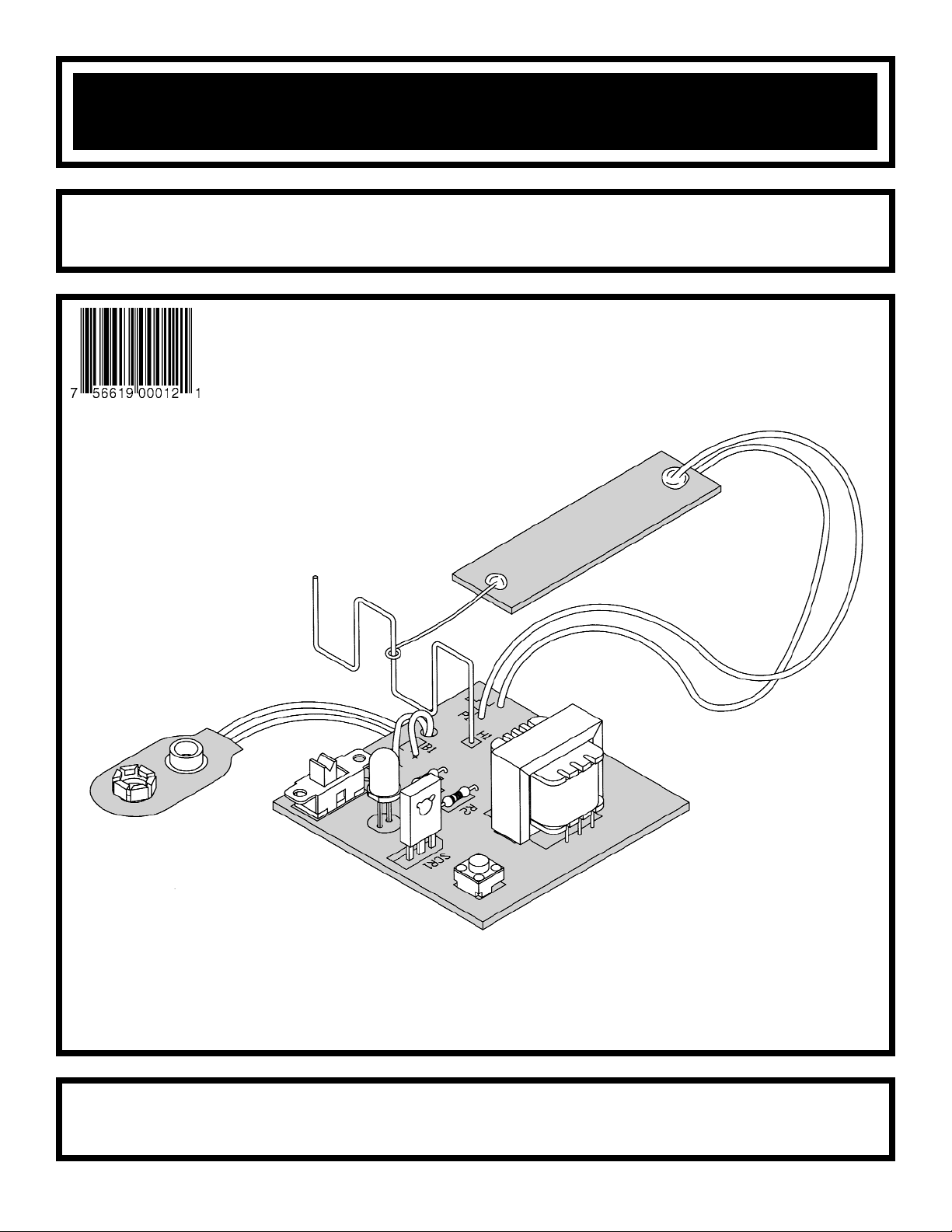
NERVE TESTER KIT
MODEL K-20
Assembly and Instruction Manual
Copyright © 2010, 1989 by ELENCO®All rights reserved. Revised 2010 REV-H 753220
No part of this book shall be reproduced by any means; electronic, photocopying, or otherwise without written permission from the publisher.
ELENCO
®
Page 2
PARTS LIST
If you are a student, and any parts are missing or damaged, please see instructor or bookstore.
If you purchased this nerve tester kit from a distributor, catalog, etc., please contact ELENCO
®
(address/phone/e-mail is at the back of this manual) for additional assistance, if needed.
Parts Verification
Before beginning the assembly process, familiarize yourself with the components and this instruction book.
Verify that all of the parts are present. This is best done by checking off each item in the box provided next to
the part in the parts list.
RESISTORS
Qty. Symbol Description Color Code Part #
r 1 R1 470Ω 5% 1/4W yellow-violet-brown-gold 134700
r 1 R2 47kΩ 5% 1/4W yellow-violet-orange-gold 154700
SEMICONDUCTORS
Qty. Symbol Description Part #
r 1 SCR1 SCR C106B 319106
r 1 D1 Diode LED red 350002
MISCELLANEOUS
Qty. Symbol Description Part #
r 1 T1 Transformer 442100
r 1 P1 Double Sided PC Board 510320
r 1 PC Board 518020
r 1 S1 Switch Push Button 540100
r 1 S2 Switch Slide 541102
r 1 Solder Roll 24” 551124
r 1 B1 Battery Snap 590098
r 2 Wire 9” 814920
r 1 H1 Wire 9” Bare 845000
-1-
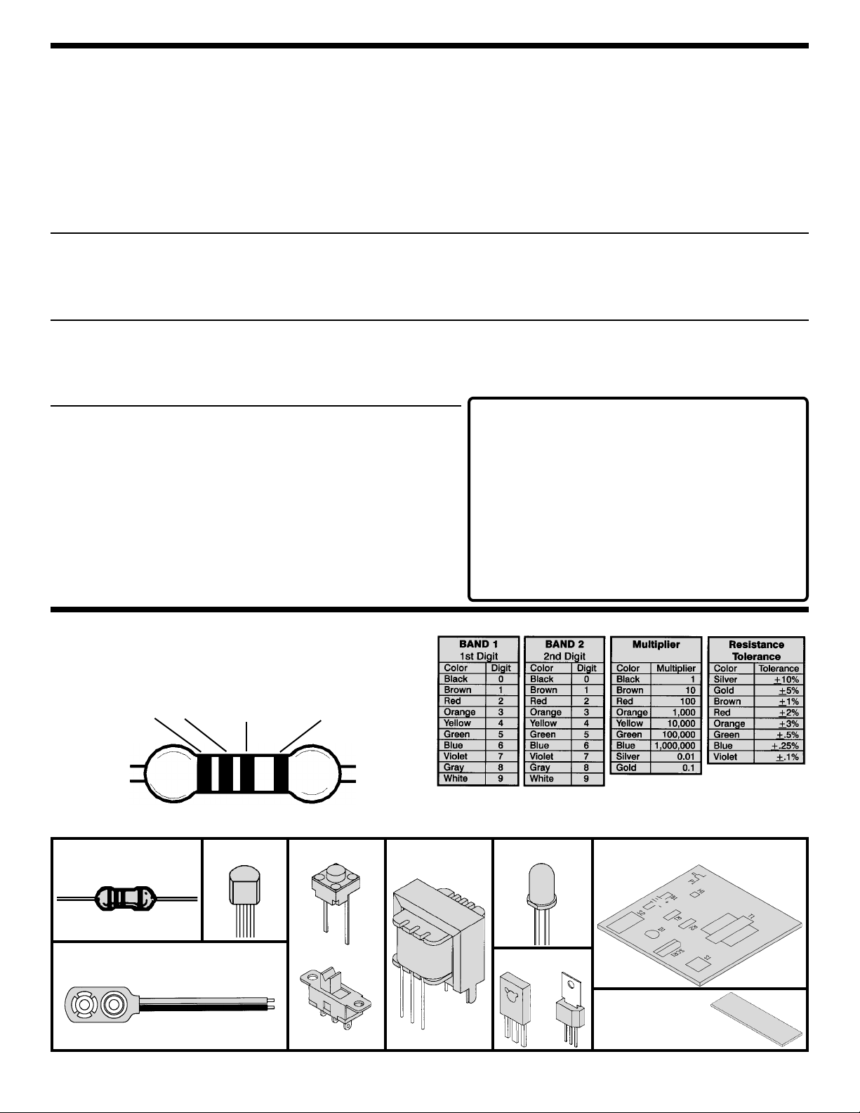
Resistor Transistor
PARTS IDENTIFICATION
Battery Snap
LEDSwitches
SCR
Slide
Push Button
Transformer
IDENTIFYING RESISTOR VALUES
Use the following information as a guide in
properly identifying the value of resistors.
BANDS
1
2 Multiplier Tolerance
PC Board
Double Sided
PC Board
OR
• Do not short circuit the battery
terminals.
• Never throw batteries in a fire
or attempt to open its outer
casing.
• Use only 9V type, alkaline
battery (not included).
• Insert battery with correct
polarity.
• Do not mix alkaline, standard
(carbon-zinc), or rechargeable
(nickel-cadmium) batteries.
• Non-rechargeable batteries
should not be recharged.
Rechargeable batteries should
only be charged under adult
supervision, and should not be
recharged while in the product.
• Remove the battery when it is
used up.
• Batteries are harmful if
swallowed, so keep away from
small children.
Batteries:
Page 3
-2-
INTRODUCTION
Test your nerve with the Nerve Tester Kit. It takes a steady hand, should you touch the twisted wire with the
probe, a slight electrical shock will be felt. The shock is very weak and harmless. For the weak of heart or
“chickens” a switch removes the electrical shock and substitutes a Light Emitting Diode (LED) which lights up
when the probe touches the wire.
THEORY OF OPERATION
The circuit of the Nerve Tester is shown on page 6 of this manual. The circuit consists of two basic circuits. One
is the high voltage generator and the other the LED with its latch circuit. We shall study each circuit further.
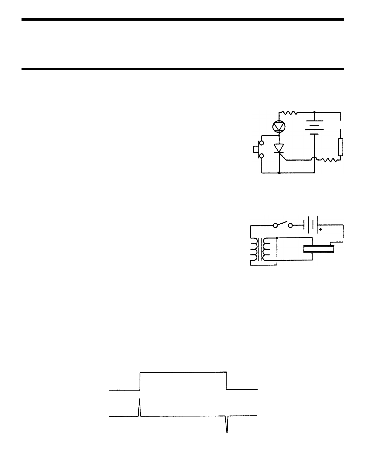
THE LED CIRCUIT
Figure 1 shows the basic LED circuit. Note that the battery is placed in a
series circuit with resistor R1, the LED and the Silicon Controlled Rectifier
(SCR). The positive voltage of the battery is placed on the anode of the SCR.
The negative voltage is connected to the cathode. Under these conditions if
a positive voltage is placed on the gate of the SCR, even for a 1/1000 of a
second, the SCR will conduct current and keep conducting when the positive
voltage is removed from the gate. This will keep the LED lit until the voltage
is removed from the SCR. This is done by closing switch 1, which shorts out
the SCR. Resistors R1 and R2 are needed to limit the current in the LED and
SCR.
THE SHOCKER GENERATOR
Figure 2 shows the basic circuit used to produce the high voltage of the
shocker generator. The heart of this circuit is the transformer. We shall review
the operation of a transformer to understand the circuit.
A transformer has two or more windings around an iron core. If a changing
current is placed in one of the windings, it will appear in the other winding.
The voltage across the second winding will be the ratio of the turns of the
transformer. If the first winding has 100 turns and the second has 1,000 turns
(10:1 ratio) the secondary voltage will be 10 times the primary voltage. In our
transformer, the ratio is 30:1. Therefore, the 9V battery voltage will be
stepped up to 270V on the secondary.
The primary wire of the transformer is connected to the negative side of the battery. The positive side of the
battery is connected to the twisted wire. The other primary wire is connected to the probe. When the probe
touches the twisted wire, a DC current flows through the primary of the transformer. The secondary of the
transformer will only have voltage the instant the probe touches the twisted wire and the instant the probe leaves
the wire. Again, only when the current changes. Refer to Figure 3 and note that there are two voltage spikes
for each time the probe touches the twisted wire. This is because the current changes twice.
Note that the probe is double-sided copper with an insulation in between. One side is negative (ground), the
other side connects to the high voltage. Your hand touches both plates and therefore you feel the shock.
LED
R1
S1
Cathode
Gate
Anode
SCR
Wire
Probe
R2
Figure 1
T1
S2
Wire
Probe
Figure 2
Figure 3
Current in
Primary
Voltage in
Secondary
+270
–270
Max
Zero
Page 4

-3-
CONSTRUCTION
Solder
Soldering Iron
Foil
Solder
Soldering Iron
Foil
Component Lead
Soldering Iron
Circuit Board
Foil
Rosin
Soldering iron positioned
incorrectly.
Solder
Gap
Component Lead
Solder
Soldering Iron
Drag
Foil
1. Solder all components from the
copper foil side only. Push the
soldering iron tip against both the
lead and the circuit board foil.
2. Apply a small amount of solder to
the iron tip. This allows the heat to
leave the iron and onto the foil.
Immediately apply solder to the
opposite side of the connection,
away from the iron. Allow the
heated component and the circuit
foil to melt the solder.
1. Insufficient heat - the solder will
not flow onto the lead as shown.
3. Allow the solder to flow around
the connection. Then, remove
the solder and the iron and let the
connection cool. The solder
should have flowed smoothly and
not lump around the wire lead.
4.
Here is what a good solder
connection looks like.
2. Insufficient solder - let the
solder flow over the connection
until it is covered.
Use just enough solder to cover
the connection.
3. Excessive solder - could make
connections that you did not
intend to between adjacent foil
areas or terminals.
4. Solder bridges - occur when
solder runs between circuit paths
and creates a short circuit. This is
usually caused by using too much
solder.
To correct this, simply drag your
soldering iron across the solder
bridge as shown.
What Good Soldering Looks Like
A good solder connection should be bright, shiny, smooth, and uniformly
flowed over all surfaces.
Types of Poor Soldering Connections
Introduction
The most important factor in assembling your K-20 Nerve Tester Kit is
good soldering techniques. Using the proper soldering iron is of prime
importance. A small pencil type soldering iron of 25 - 40 watts is
recommended. The tip of the iron must be kept clean at all times and
well-tinned.
Solder
For many years leaded solder was the most common type of solder
used by the electronics industry, but it is now being replaced by leadfree solder for health reasons. This kit contains lead-free solder, which
contains 99.3% tin, 0.7% copper, and has a rosin-flux core.
Lead-free solder is different from lead solder: It has a higher melting
point than lead solder, so you need higher temperature for the solder to
flow properly. Recommended tip temperature is approximately 700
O
F;
higher temperatures improve solder flow but accelerate tip decay. An
increase in soldering time may be required to achieve good results.
Soldering iron tips wear out faster since lead-free solders are more
corrosive and the higher soldering temperatures accelerate corrosion,
so proper tip care is important. The solder joint finish will look slightly
duller with lead-free solders.
Use these procedures to increase the life of your soldering iron tip when
using lead-free solder:
• Keep the iron tinned at all times.
• Use the correct tip size for best heat transfer. The conical tip is the
most commonly used.
• Turn off iron when not in use or reduce temperature setting when
using a soldering station.
•
Tips should be cleaned frequently to remove oxidation before it becomes
impossible to remove. Use Dry Tip Cleaner (Elenco
®
#SH-1025) or Tip
Cleaner (Elenco®#TTC1). If you use a sponge to clean your tip, then use
distilled water (tap water has impurities that accelerate corrosion).
Safety Procedures
• Always wear safety glasses or safety goggles to
protect your eyes when working with tools or
soldering iron, and during all phases of testing.
• Be sure there is adequate ventilation when soldering.
• Locate soldering iron in an area where you do not have to go around
it or reach over it. Keep it in a safe area away from the reach of
children.
• Do not hold solder in your mouth. Solder is a toxic substance.
Wash hands thoroughly after handling solder.
Assemble Components
In all of the following assembly steps, the components must be installed
on the top side of the PC board unless otherwise indicated. The top
legend shows where each component goes. The leads pass through the
corresponding holes in the board and are soldered on the foil side.
Use only rosin core solder.
DO NOT USE ACID CORE SOLDER!
'
Page 5

-4-
ASSEMBLE COMPONENTS TO THE PC BOARD
P1 - Probe (see Figure A)
H1 - Twisted Wire (see Figure B)
B1 - Battery Snap
(see Figure C)
D1 - LED Red
(see Figure D)
S2 - SPDT Slide Switch
T1 - Transformer
Insert the transformer into the PC board
as shown. Solder the five leads into place
and cut off the excess leads.
R2 - 47kΩ 5% 1/4W Resistor
(yellow-violet-orange-gold)
R1 - 470Ω 5% 1/4W Resistor
(yellow-violet-brown-gold)
SCR1 - C106B SCR
(see Figure E)
S1 - Push Button Switch
Figure A
Assemble the probe (P1). Solder an excess
lead from the resistors to a side of the double
sided PC board. Leave 1/2 inch extending from
the end. Form a loop at the end of the wire.
Cut two 9 inch wires and strip 1/2 inch of
insulation off of both ends. Solder a wire to
each side of the double sided PC board. Insert
the other ends of the wires in the holes marked
P1. Solder and cut off the excess leads.
Figure B
Bend the 9” bare wire into the shape as shown
below. Insert one end of the wire into the PC
board, in the hole marked H1 and solder into
place.
Figure C
Insert the battery snap wire through the PC
board as shown. Then, insert the red wire
into the positive (+) hole and the black wire
into the negative (–) hole. Solder and cut off
the excess leads.
Figure D
Mount the LED with the flat side of its body
in the direction as marked on the top
legend. Leave 1/4” between the LED and
the surface of the PC board. Solder and cut
off the excess leads.
Figure E
Mount the silicon controlled rectifier (SCR)
with the back side (metal backing) in the
same direction as the marking on the PC
board as shown.
B1
Flat Side
1/4”
Back Side
PC Board
Marking
PC Board
Marking
B
A
Page 6

COMPONENT CHECK
1. Be sure that all components have been mounted in their correct places.
2. Has the LED D1 been installed correctly? The flat side of its body should be in the hole as shown on the top
legend. If the LED is in backwards, it will not light.
3. Pay close attention to the red and black wires of the battery snap. The red wire should be installed in the
positive (+) hole and the black wire in the negative (–) hole. Snap in a fresh 9-volt battery.
OPERATING THE K-20
1. Grasp the probe so that you touch the copper on both sides of the probe.
2. Try to guide the loop along the wire. If the
loop touches the wire, you will receive a
mild shock or throw the slide switch S2
and the LED will light instead.
3. Push switch S1 to reset the LED.
TROUBLESHOOTING
Contact ELENCO®if you have any problems. DO NOT contact your place of purchase as they will not be able
to help you.
1. One of the most frequently occurring problems is poor solder connections. Tug slightly on all parts to make
sure that they are indeed soldered.
2. All solder connections should be shiny. Resolder any that are not.
3. Solder should flow into a smooth puddle rather than a round ball. Resolder any connection that has formed
into a ball.
4. Have any solder bridges formed? A solder bridge may occur if you accidentally touch an adjacent foil by
using too much solder or by dragging the soldering iron across adjacent foils. Break the bridge with your
soldering iron.
LED CIRCUIT REMEDY
1.
LED - Move switch S2 into position A (shown on the top legend drawing in the assembly manual). Place a cliplead from the cathode lead of the LED (the lead on the flat side) to the negative terminal of the 9-volt battery.
The LED should light. If the LED does not light, the problem is with the LED or resistor R1. If the LED is
installed with the flat side in the correct direction and R1 is the correct value, then most likely the LED is at fault.
2. SCR - Move switch S2 into position A. Place a clip-lead from the gate (G) of the SCR to the positive
terminal of the battery. The LED should light even when the clip-lead is removed. If not, the problem
could be with S1, be sure that S1 is in the open position first. If you get no response, place a cliplead from the center lug to the position A lug of switch S2. If the circuit works now, the problem was
S2. If the circuit still does not work, the problem is the SCR.
SHOCKER GENERATOR REMEDY
1. TRANSFORMER - Be sure that the transformer is installed correctly, with the three lead side in the direction
as shown in the top legend drawing in this manual.
2.
S2 - Place a clip-lead from the center lug to position B. If the shocker circuit now works, the problem is with S2.
-5-
CAG
Page 7

-6-
SCHEMATIC DIAGRAM
QUIZ
1. The nerve tester produces a ______________ whenever the probe touches the twisted wire.
2. A “chicken” afraid of the shock will switch the nerve tester to the ______________ position.
3. The LED will light when a positive voltage touches the ___________ of the SCR.
4. Once the LED is lit, removing the probe from the twisted wire will turn off the LED. (true or false)
5. A transformer has ___________ or more windings.
6. A _______________ current in the primary winding will produce voltage in the ___________ winding.
7. The voltage in the secondary winding is equal to the primary voltage times the ratio of the ____________ in
the transformer.
8. The nerve tester produces about a ____________ volt spike for a very short time.
9. There are ___________ spikes of voltage every time the probe touches the twisted wire.
10. The probe has ___________ sides of copper between an insulator.
Answers: 1. shock; 2. LED; 3. gate; 4. false; 5. two; 6. DC, secondary; 7. turns; 8. 270; 9. two; 10. two
B1
R1
470Ω
R2
47kΩ
T1
S2
S1
A
B
D1
LED
C106B
SCR1
H1
P1
Probe
Page 8

ELENCO
®
150 Carpenter Avenue
Wheeling, IL 60090
(847) 541-3800
Website: www.elenco.com
e-mail: elenco@elenco.com
 Loading...