

Page 1

Copyright © by Elenco®Electronics, Inc. All rights reserved. No part of this book shall be reproduced by 753285
any means; electronic, photocopying, or otherwise without written permission from the publisher.
Patents: 7,144,255; 7,273,377; & other patents pending
Page 2
-1-
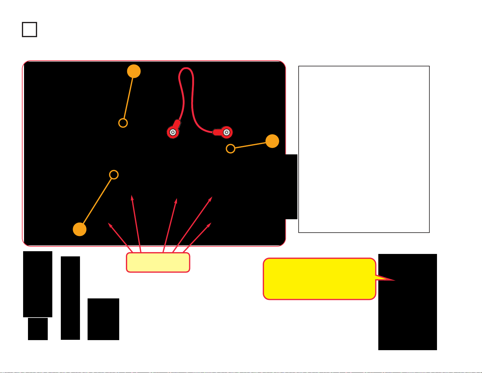
1. Most circuit problems are due to incorrect assembly,
always double-chec k that your cir cuit exactl y matches
the drawing for it.
2. Be sure that parts with positive/negative markings are
positioned as per the drawing.
3. Be sure that all connections are securely snapped.
4. Try replacing the batteries.
5. If the motor spins but does not balance the fan, c heck
the black plastic piece with three prongs on the motor
shaft, and replace it if it is damaged (this kit includes
a spare). To replace , pry the broken one off the motor
shaft using a screwdriver, then push the new one on.
6. If a fiber optics circuit isn’t working, make sure the
clear & black cable holder s are pushed all the way onto
the LED/phototransistor, and the fiber optic cable is
pushed into the holders as far as it will go. The cable
should be standing straight up in th holders.
ELENCO
®
is not responsible for parts damaged due to
incorrect wiring.
Basic T roubleshooting
Note: If you suspect you have damaged parts, you can follow the
Advanced Troubleshooting procedure on page 15 to determine which ones
need replacing.
Basic T roubleshooting 1
Parts List 2, 3
How to Use Snap Circuits
®
4, 5
About Your Snap Circuits
®
LIGHT Parts 6-8
Introduction to Electricity 9
Light in Our World 10-12
DO’s and DON’Ts of Building Circuits 13
Advanced T roubleshooting 14, 15
Project Listings 16, 17
Projects 1 - 182 18 - 81
Other Snap Circuits
®
Projects 82
WARNING: SHOCK HAZARD - Never connect Snap
Circuits®to the electrical outlets in your home in any wa y!
Table of Contents
WARNING: Al ways chec k your wiring bef ore
turning on a circuit. Never leave a circuit
unattended while the batteries are installed.
Never connect additional batteries or any
other power sources to your cir cuits. Discard
any cracked or broken parts.
Adult Supervision: Because children’s
abilities var
y so much, e ven with age groups,
adults should exercise discretion as to which
experiments are suitable and safe (the
instructions should enable supervising
adults to establish the experiment’s
suitability for the child). Make sure y our child
reads and follows all of the relevant
instructions and safety procedures, and
keeps them at hand for reference.
This product is intended for use by adults
and children who have attained sufficient
maturity to read and follow directions and
warnings.
Never modify your parts, as doing so may
disable important safety features in them,
and could put your child at risk of injury.
CAUTION: Persons who are extremely
sensitive to flashing lights and rapidl
y
c
hanging colors or patterns should exercise
caution when playing with this toy.
CAUTION: High intensity light. Do not look
directly at white LED (D6).
W ARNING FOR ALL PROJECTS WITH A SYMBOL - Moving parts. Do not touch the motor or fan during operation.
Do not lean over the motor. Do not launch the fan at people, animals, or objects. Eye protection is recommended.
!
!
!
WARNING: CHOKING HAZARD -
Small parts. Not for children under 3 years.
!
Conforms to
ASTM
F963-96A
• Use only 1.5V AA type, alkaline batteries (not
included).
• Insert batteries with correct polarity.
• Non-rechargeable batteries should not be
recharged. Rechargeable batteries should
only be charged under adult supervision, and
should not be recharged while in the product.
• Do not mix old and new batteries.
• Do not connect batteries or battery holders in
parallel.
• Do not mix alkaline, standard (carbon-zinc),
or rechargeable (nickel-cadmium) batteries.
• Remove batteries when they are used up.
• Do not short circuit the battery terminals.
• Never throw batteries in a fire or attempt to
open its outer casing.
• Batteries are harmful if swallowed, so keep
away from small children.
Batteries:
!
Apple Inc. is not affiliated with nor endorses this product. iPod®is a registered trademark of Apple Inc.
Page 3

-2-
Important: If any parts are missing or damaged, DO NOT RETURN TO RETAILER. Call toll-free (800) 533-2441 or e-mail us at:
help@elenco.com. Customer Service • 150 Carpenter Ave. • Wheeling, IL 60090 U.S.A.
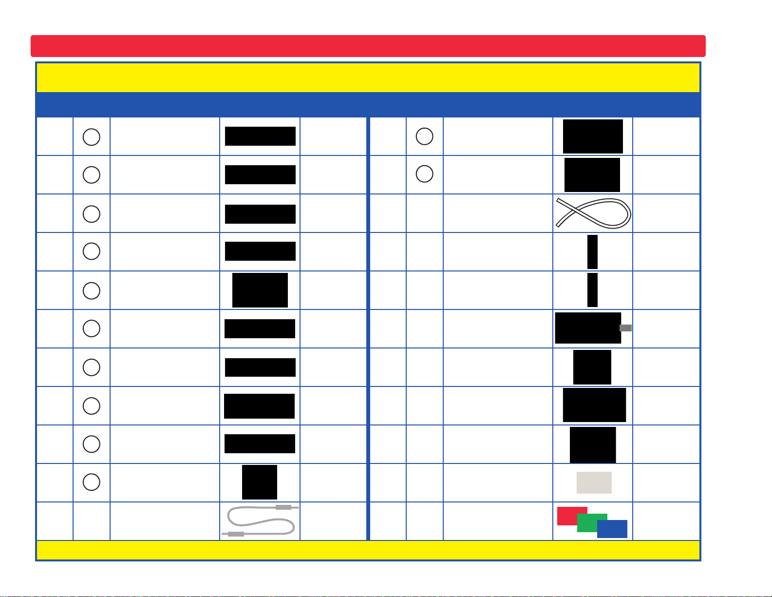
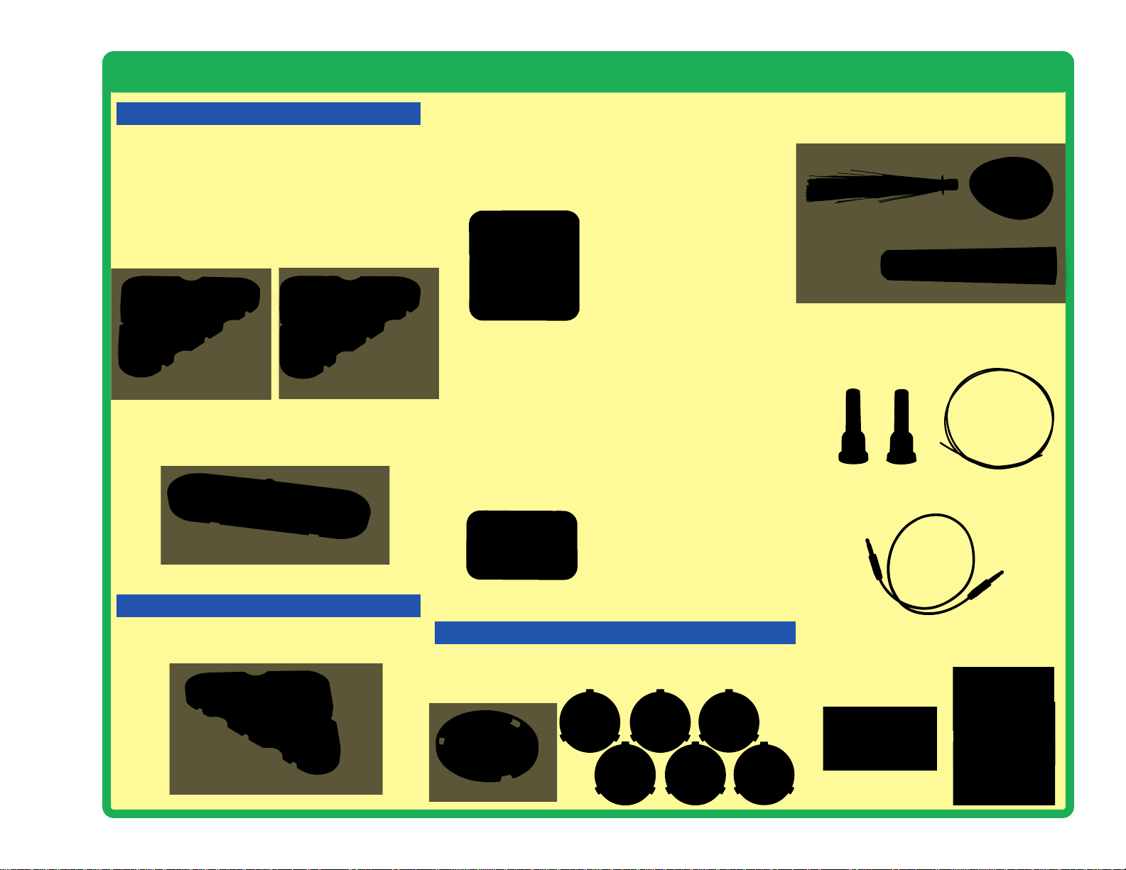
Parts List (Colors and styles may vary) Symbols and Numbers (page 1)
Qty. ID Name Symbol Part # Qty. ID Name Symbol Part #
1
Base Grid
(11.0” x 7.7”)
6SCBG
1
White Light Emitting
Diode (LED)
6SCD6
3
1-Snap Wire 6SC01
1
Color Light Emitting
Diode (LED)
6SCD8
6
2-Snap Wire 6SC02
1
Jumper Wire (black) 6SCJ1
3
3-Snap Wire 6SC03
1
Jumper Wire (red) 6SCJ2
1
4-Snap Wire 6SC04
1
Motor 6SCM1
1
5-Snap Wire 6SC05
1
Spare Motor Top 6SCM1T
1
6-Snap Wire 6SC06
1
Glow Fan Blade 6SCM1FG
2
Battery Holder - uses
two (2) 1.5V type “AA”
(not Included)
6SCB1
1
Disc Holder 6SCM1DH
1
0.1µF Capacitor
6SCC2
1
Set of Disc Cutouts
(6 pcs. / set)
6SCM1DS
1
100µF Capacitor
6SCC4
1
PNP Transistor 6SCQ1
1
Red Light Emitting
Diode (LED)
6SCD1
1
NPN Transistor 6SCQ2
You may order additional / replacement parts at our website: www.snapcircuits.net
5
4
3
2
1
Q1
C2
D1
C4
Q2
6
B1
D8
M1
D6
Page 4
-3-
Important: If any parts are missing or damaged, DO NOT RETURN TO RETAILER. Call toll-free (800) 533-2441 or e-mail us at:
help@elenco.com. Customer Service • 150 Carpenter Ave. • Wheeling, IL 60090 U.S.A.
Parts List (Colors and styles may vary) Symbols and Numbers (page 2)
Qty. ID Name Symbol Part # Qty. ID Name Symbol Part #
1
Phototransistor 6SCQ4
1
Strobe IC 6SCU23
1
100Ω Resistor
6SCR1
1
Infrared Receiver 6SCU24
1
5.1kΩ Resistor
6SCR3
1
Fiber Optic Cable 6SCFC
1
100kΩ Resistor
6SCR5
1
Fiber Optic Cable
Holder, clear
6SCFCHC
1
Adjustable Resistor 6SCRV
1
Fiber Optic Cable
Holder, black
6SCFCHB
1
Slide Switch 6SCS1
1
Fiber Optic Tree 6SCFT
1
Press Switch 6SCS2
1
Mounting Base
(for fiber optic tree)
6SCFMB
1
Speaker 6SCSP
1
Tower LED
Attachment
6SCTOWER
1
Microphone 6SCX1
1
Egg LED Attachment 6SCEGG
1
Color Organ 6SCU22
1
Prismatic Film 6SCFILM
1
Stereo Cable 9TLSCST
1
Red/Green/Blue
Filters Set
6SCFRGB
You may order additional / replacement parts at our website: www.snapcircuits.net
S1
RV
R5
R3
R1
X1
U22
S2
SP
U24
U23
Q4
Page 5

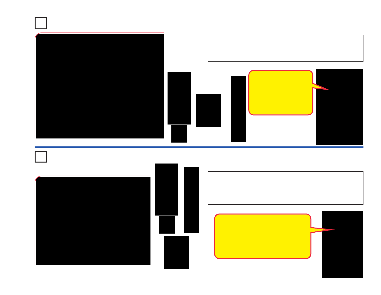
How to Use Snap Circuits
®
Snap Circuits
®
uses building blocks with snaps
to build the different electrical and electronic
circuits in the projects. Each block has a
function: there are switch blocks, light blocks,
battery blocks, different length wire b locks , etc.
These blocks are different colors and have
numbers on them so that you can easily
identify them. The blocks you will be using are
shown as color symbols with level numbers
next to them, allowing you to easily snap them
together to form a circuit.
For Example:
This is the switch bloc k which is green and has
the marking on it. The par t symbols in this
booklet may not exactly match the appear ance
of the actual parts, but will clearly identify them.
This is a wire block which is blue and comes
in different wire lengths.
This one has the number , , , ,
or on it depending on the length of the wire
connection required.
There is also a 1-snap wire that is used as a
spacer or for interconnection between diff erent
layers.
You need a power source to build each circuit.
This is labeled and requires two (2) 1.5V
“AA” batteries (not included).
A large clear plastic base grid is included with
this kit to help keep the circuit blocks properly
spaced. You will see evenly spaced posts that
the different blocks snap into. The base has
rows labeled A-G and columns labeled 1-10.
Next to each part in every circuit drawing is a
small number in black. This tells you which
level the component is placed at. Place all
parts on level 1 first, then all of the parts on
level 2, then all of the parts on level 3, etc.
Some circuits use the jumper wires to make
unusual connections. Just clip them to the
metal snaps or as indicated.
Usually when the motor is used, the glow
fan will usually be placed on it. On top of the
motor shaft is a black plastic piece (the motor
top) with three little tabs. Lay the fan on the
black piece so the slots in its bottom “fall into
place” around the three tabs in the motor top.
If not placed properly, the fan will fall off when
the motor starts to spin.
This set contains 6 pre-punched cardboard
discs. These will be used with a strobe light in
project 46 and others. The discs may be
supplied as a single sheet; just punch them
out.
To remove a disc
from the holder, use
your fingernail, or
use a pencil to push
it up from beneath
one of the tabs.
S2
2
3 4 5
6
B1
M1
-4-
Page 6
-5-
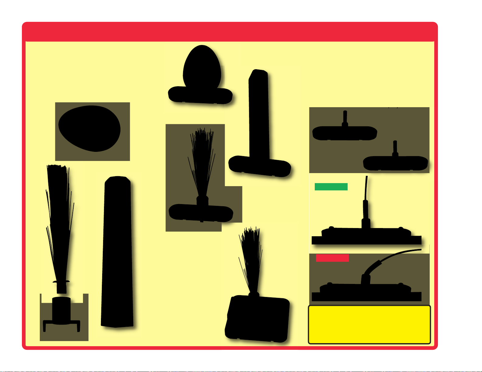
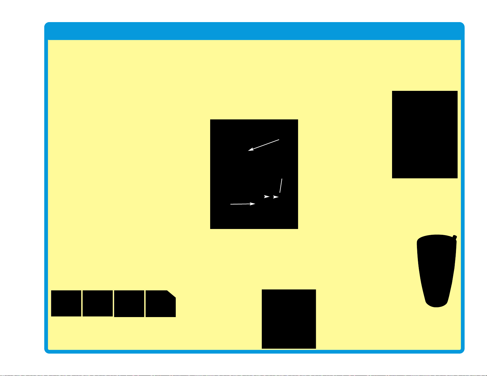
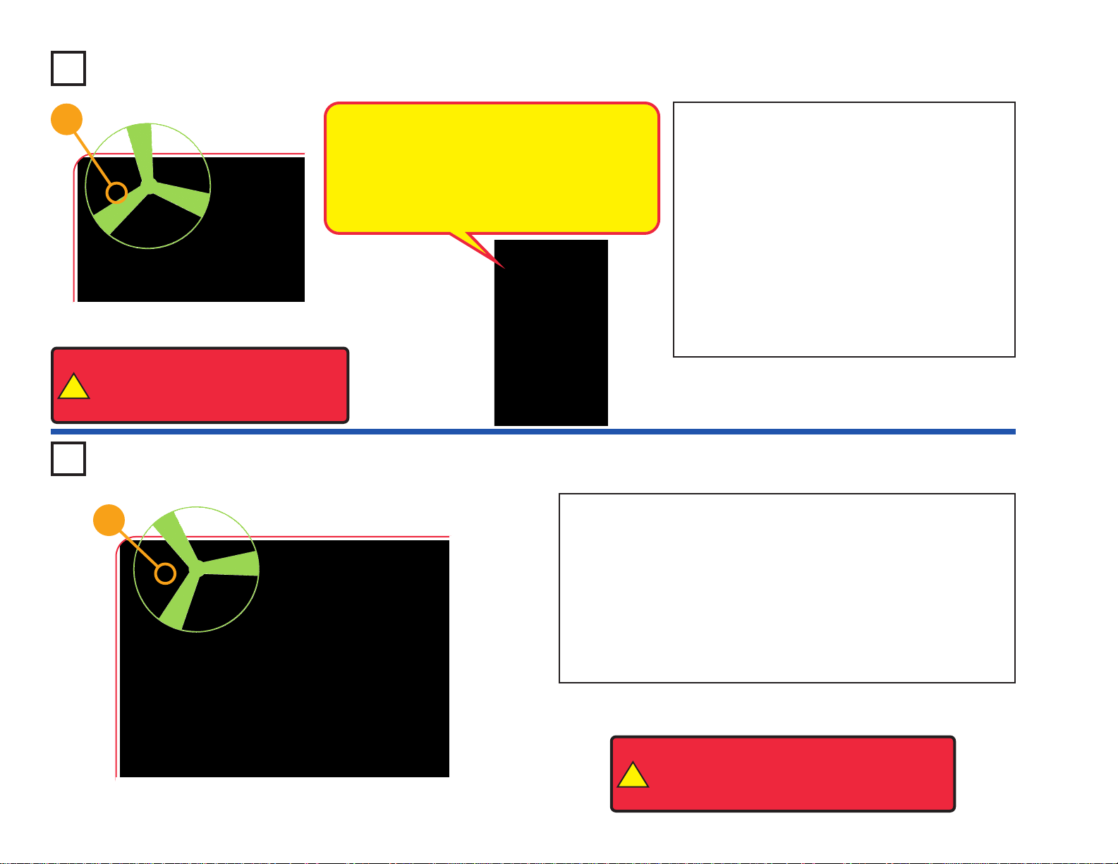
How to Use Snap Circuits
®
This set contains three LED attachments,
which can be mounted on the LED modules
(D1, D6, D8, and on U22) to enhance their
light eff
ects. The egg and tower attachments
are mounted directly on the LEDs, but the fiber
optic tree must be mounted using the
mounting base, as shown. This is described in
the projects.
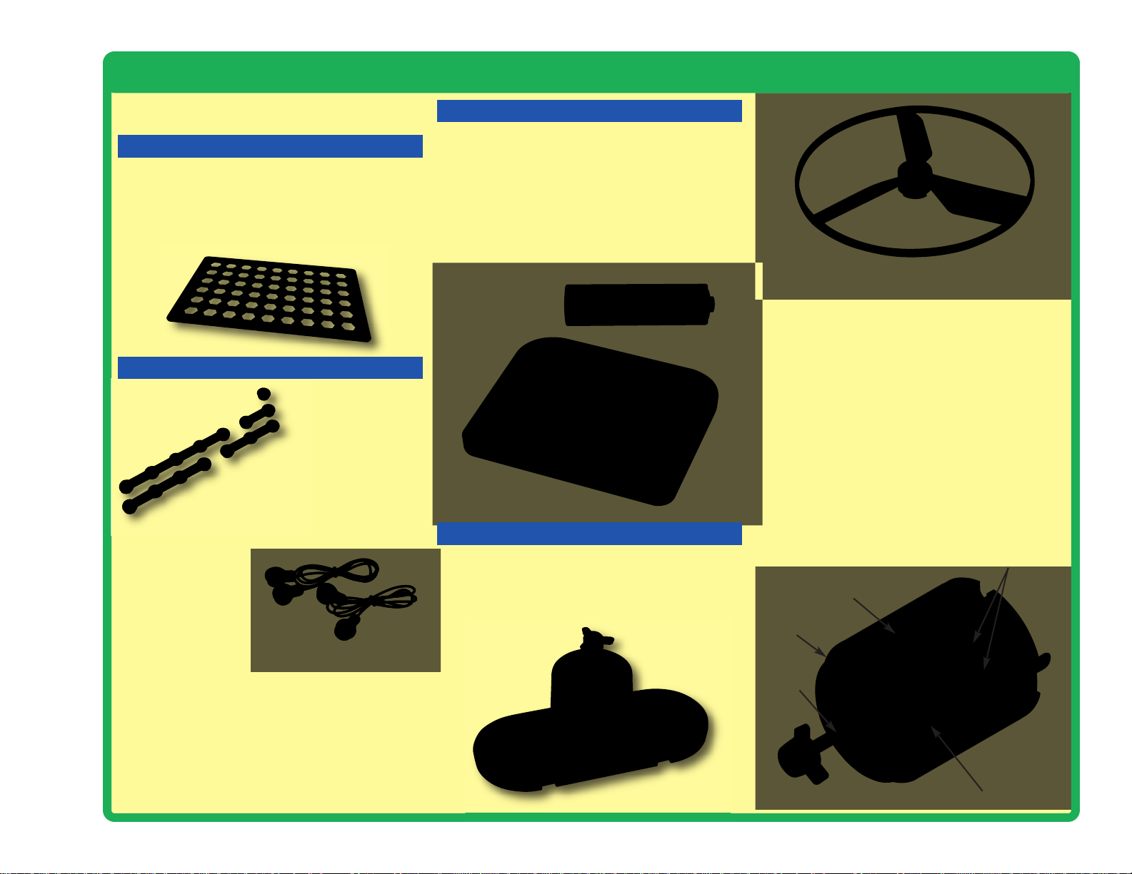
In some projects, the fiber optic cable will be
mounted on the LEDs (D1, D6, D8, and on
U22) or the phototransistor (Q4). This is done
by placing the clear and black cable holders
onto the LED/phototransistor, then inserting
the fiber optic cable all the way into the holder.
For best performance the cable should stand
straight up in the holders, without bending
them. This is described in the projects.
Light T ower
Correct
Incorrect
Fiber Optic Tree
LED attachment
mounted to D8
Light T ower
LED attachment
mounted to D1
Fiber Optic Tree
LED attachment
mounted to U22
Egg LED attachment
mounted to D6
Note: While building the projects, be
careful not to accidentally make a direct
connection across the battery holder (a
“short circuit”), as this may damage and/or
quickly drain the batteries.
Egg
Fiber Optic Tree
Black cable holder
mounted to Q4
Clear cable holder
mounted to D1
Page 7
-6-
About Your Snap Circuits
®
LIGHT Parts
(Part designs are subject to change without
notice).
BASE GRID
The blue snap wires
are wires used to
connect components.
They are used to
transport electricity and do
not affect circuit performance.
They come in different lengths to
allow orderly arrangement of connections
on the base grid.
The red and black
jumper wires make
flexible connections for
times when using the snap wires
would be difficult. They also are
used to make connections off the base grid.
Wires transport electricity just like pipes are used
to transport water. The colorful plastic coating
protects them and prevents electricity from
getting in or out.
Glow-in-the-dark Fan
Electromagnet
Shaft
Shell
Magnet
Power Contacts
BATTERY HOLDER
How does electricity turn the shaft in the motor?
The answer is magnetism. Electricity is closely
related to magnetism, and an electric current
flowing in a wire has a magnetic field similar to
that of a very, very tiny magnet. Inside the motor
is a coil of wire with many loops wrapped around
metal plates. This is called an electromagnet. If
a large electric current flows through the loops, it
will turn ordinary metal into a magnet. The motor
shell also has a magnet on it. When electricity
flows through the electromagnet, it repels from
the magnet on the motor shell and the shaft
spins. If the fan is on the motor shaft, then its
blades will create airflow.
Motor (M1)
The base grid is a platfor m for mounting parts
and wires. It functions like the printed circuit
boards used in most electronic products, or like
how the walls are used for mounting the electrical
wiring in your home.
SNAP WIRES & JUMPER WIRES
The motor (M1) converts electricity into
mechanical motion. An electric current in the
motor will turn the shaft and the motor blades,
and the fan blade if it is on the motor.
The batteries (B1) produce an electrical voltage
using a chemical reaction. This “voltage” can be
thought of as electrical pressure
, pushing
electricity through a circuit just like a pump
pushes water through pipes. This v oltage is much
lower and much safer than that used in your
house wiring. Using more batteries increases the
“pressure”, therefore, more electricity flows.
Battery Holder (B1)
MOTOR
Page 8

About Your Snap Circuits
®
LIGHT Parts
RESISTORS LEDs
-7-
Adjustable Resistor (RV)
Resistors (R1, R3, & R5)
SLIDE & PRESS SWITCHES
The speaker (SP) converts
electricity into sound by
making mechanical vibrations. These vibrations
create variations in air
pressure, which travel
across the room. You
“hear” sound when
your ears feel these air
pressure variations.
SPEAKER
Speaker (SP)
The adjustable resistor (RV) is a 50kΩ resistor
but with a center tap that can be adjusted
between 200Ω and 50kΩ.
Resistors “resist” the flow of electricity and are
used to control or limit the current in a circuit.
Snap Circuits
®
LIGHT includes 100Ω (R1), 5.1kΩ
(R3), and 100kΩ (R5) resistors (“k” symbolizes
1,000, so R5 is really 100,000Ω). Materials like
metal have very low resistance (<1Ω), while
materials like paper, plastic, and air have nearinfinite resistance. Increasing circuit resistance
reduces the flow of electricity.
The slide & press switches (S1 & S2) connect
(pressed or “ON”) or disconnect (not pressed or
“OFF”) the wires in a circuit. When ON they have no
effect on circuit performance. Switches turn on
electricity just like a faucet turns on water from a pipe.
Slide & Press
Switches
(S1 & S2)
LED’s
(D1, D6, & D8)
The red, white, and color LED’s (D1, D6, & D8)
are light emitting diodes, and may be thought of
as a special one-way light bulbs. In the “forward”
direction, (indicated by the “arrow” in the symbol)
electricity flows if the voltage exceeds a turn-on
threshold (about 1.5V for red, about 3.0V for
white, and in between for other colors);
brightness then increases. The color LED
contains red, green, and blue LEDs, with a microcircuit controlling then. A high current will bur n
out an LED, so the current must be limited by
other components in the circuit. LED’s block
electricity in the “reverse” direction.
CAPACITOR
The 0.1µF and 100µF capacitors (C2 & C4)can
store electrical pressure (voltage) for periods of
time. This storage ability allows them to block
stable voltage signals and pass changing ones.
Capacitors are used for filtering and delay
circuits.
Capacitors
(C2 & C4)
Microphone (X1)
The microphone (X1) is actually a resistor that
changes in value when changes in air pressure
(sounds) apply pressure to its surface. Its
resistance typically varies between 1kΩ and
10kΩ.
MICROPHONE
Page 9
-8-
About Your Snap Circuits
®
LIGHT Parts
TRANSISTORS
The phototransistor (Q4) is a transistor that
uses light to control electric current.
Phototransistor (Q4)
ELECTRONIC MODULES
(+)
NC
OUT
(–)
CTL
Connections:
(+) - power from batteries
(–) - power return to batteries
OUT - output connection
CTL - strobe speed control
NC - not used
See project 46 for example of
proper connections.
B
(+)
FB
Connections:
R - red color control
G - green color control
B - blue color control
(+) - power from batteries
INP - circuit input
FB - feedback connection
(–) - power return to batteries
IN - audio input jack
OUT - audio output jack
See projects 5, 6, 33, and 34 for
examples of proper connections.
INP(–)
G
R
The color organ (U22) contains resistors, capacitors,
transistors, a tri-color LED, and integrated circuits. The
LED in it can change colors by direct control, or in synch
with an audio input signal. A schematic f or it is a vailab le at
www.snapcircuits.net/faq.
OUT
IN
The strobe IC (U23) contains resistors, capacitors, and
transistors that are needed to make a strobe light circuit.
A schematic for it is av ailab le at www.snapcircuits.net/faq.
Infrared module (U24)
OTHER PARTS
The stereo cable is used to connect
your music device to the color organ
(U22).
Prismatic film separates light into
different colors. The red, green, & blue
filters filter out colors.
The disc holder and discs produce amazing effects when
used with the Strobe Effects circuit (project 46).
The Infrared module (U24) is a miniaturized
infrared receiver circuit for remote control.
The PNP & NPN transistors (Q1 & Q2) are
components that use a small electric current to
control a large current, and are used in switching,
amplifier, and buffering applications. They are
easy to miniaturize, and are the main building
blocks of integrated circuits including the
microprocessor and memory circuits in
computers.
PNP & NPN Transistors (Q1 & Q2)
The LED attachments can be used with
any of the LEDs (red, white, color, and
the color organ) to enhance the light
effects.
The fiber optic cable carries light
between two places. The light can be
encoded to transmit information. The
clear and black holders are used to
attach it to circuits.
Fiber Optic Tree
Light
Tower
Egg
Page 10

-9-
Introduction to Electricity
What is electricity? Nobody really knows. We only know how to produce it,
understand its properties, and how to control it. Electricity is the mov ement of subatomic charged particles (called electrons) through a material due to electrical
pressure across the material, such as from a battery.
Power sources, such as batteries, push electricity through a circuit, like a pump
pushes water through pipes. Wires carry electricity , lik e pipes carry water . De vices
like LEDs, motors, and speak ers use the energy in electricity to do things. Switches
and transistors control the flow of electricity like valves and faucets control water.
Resistors limit the flow of electricity.
The electrical pressure exerted by a battery or other power source is called
voltage and is measured in volts (V). Notice the “+” and “–” signs on the battery;
these indicate which direction the battery will “pump” the electricity.
The electric current is a measure of how fast electricity is flowing in a wire, just
as the water current describes how fast water is flowing in a pipe. It is expressed
in amperes (A) or milliamps (mA, 1/1000 of an ampere).
The “power” of electricity is a measure of how fast energy is moving through a
wire. It is a combination of the voltage and current (Power = Voltage x Current). It
is expressed in watts (W).
The resistance of a component or circuit represents how much it resists the
electrical pressure (voltage) and limits the flow of electric current. The relationship
is Voltage = Current x Resistance. When the resistance increases, less current
flows. Resistance is measured in ohms (Ω), or kilo ohms (kΩ, 1000 ohms).
Nearly all of the electricity used in our world is produced at enormous generators
driven by steam or water pressure. Wires are used to efficiently transport this
energy to homes and businesses where it is used. Motors convert the electr icity
back into mechanical form to drive machinery and appliances. The most important
aspect of electricity in our society is that it allows energy to be easily transported
over distances.
Note that “distances” includes not just large distances but also tiny distances. Try
to imagine a plumbing structure of the same complexity as the circuitry inside a
portable radio - it would have to be large because we can’t make water pipes so
small. Electricity allows complex designs to be made very small.
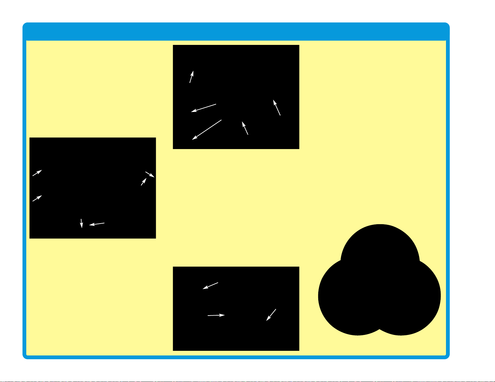
There are two ways of arranging parts in a circuit, in series or
in parallel. Here are examples:
Placing components in series increases the resistance; highest
value dominates. Placing components in par allel decreases the
resistance; lower value dominates.
The parts within these series and parallel sub-circuits may be
arranged in different ways without changing what the circuit
does. Large circuits are made of combinations of smaller series
and parallel circuits.
Series Circuit
Parallel Circuit
Page 11
Light in Our World
-10-
What would our world be like without light?
Moving and doing things in total darkness
would be much more difficult, because
everyone would be blind. Plants rely on
sunlight for energy and would die without it. If
all the plants die, then people and animals
would have nothing to eat, and would starve.
Let’s hope we never have to live in a world
without light.
Light is energy, traveling at high speed.
Sunlight can warm up your skin, as can bright
lights in a concert hall or playhouse. Light can
carry information. For example, our brains
analyze the light received in our ey es , to learn
what is around us. In fiber optic cables , beams
of light carry data between cities. Infrared light
from a remote control can tell a TV to change
to a different channel.
Light moves as super-tiny charges, which are
so full of energy they go flying off in all
directions.
This happens when a material has too much
energy , and some of the energy changes f orm.
For example , a light b ulb makes light when an
electric current makes the filament so hot that
it glows. Some of the energy in a burning fire
escapes by changing to light. Our br ight sun
makes so much light because it is basically a
gigantic ball of thermonuclear reactions. Light
emitting diodes (LEDs) make light by
converting excess electrical energy.
You “see” when light enters your eyes. When
you turn on a light in a room, the light shines
on everything around it. When light shines on
something, some of the light is absorbed into
it, and the rest is reflected off. The absorbed
light is converted to heat, and the reflected
light is scattered around the room. Some of the
shining and reflected light might reach your
eyes. Your brain inter prets the light into your
eyes, and makes the mental picture you see.
When all the light shining on something is
absorbed, with none reflected towards your
eyes, then you can’t see it. The object will
appear dark. The brighter an object appears,
the more light was reflected off it and into your
eyes. Some materials, like air and clear glass,
let light pass through them.
You can only see the
moon when light from the
sun bounces off it, and
reflects to earth.
You can’t see a beam of light traveling across
a room, unless something scatters the light
and some reaches your eyes . In a dusty room,
sometimes you can see the dust particles
floating in the air when sunlight hits them.
In this photograph,
sand has been
tossed into the air,
which is illuminated
by a narrow beam of
sunlight coming down
into the canyon.
When you turn on a
light, you instantly
see everything. This
happens because
light is very fast, and
travels about 186,000
miles a second in air.
Light rays can bend when they pass between
different materials, such as air and water . Light
bends because its speed changes. The speed
of light in water is only about 125,000 miles a
second.
The part of the pen in water
looks distorted, because light
changes speed when entering
and leaving the water.
When you look directly out a
glass window, you can see
clearly through it. When you
look through the window at a
wide angle, you can see
through it, but also see a reflection in it. When
you try to look through the window at a really
wide angle, you can’t see through it at all, and
only see reflections. Try looking through a
window in your home at really wide angles.
Light bulb
filament
Glowing
light bulb
filament
Close-up
view of the
Sun
Glowing
white LED
(D6)
White light beam
Reflected light
Mental picture
Page 12
-11-
Light in Our World
When light hits a glass surface at a wide
enough angle, all the light is reflected. Fiber
optic cables have arr ays of fle xib le glass fibers.
In these cables, light rays move through by
bouncing along the inside walls at wide angles,
and can travel great distances. Light moves
through the cable ev en if it is bent a little, b ut if
there is a tight bend then most of the light will
be absorbed instead of reflected forward.
Translucent materials, such as the tower and
egg LED attachments in this set, allow some
light to pass through but scatter it around.
Color
The things around you have different colors
because they reflect the colors that you see,
while absorbing the other colors. Light
produced by the sun or a light bulb is called
white light. White light is not really a color itself ,
but is a mixture of all the colors seen in a
rainbow.
White light shines on an orange. All colors in
the light are absorbed except orange, which is
reflected off. The reflected orange light
reaches our eyes, so we see it as having
orange color.
White light can be split up into its different
colors. This happens when light passes
between different materials, and the different
colors in it are bent by different amounts. You
can see this by viewing white light through
prismatic film, as you do in project 67.
Sometimes water in the air can bend sunlight
by just the right amounts, and make a rainbow.
Color filters allow one color to pass through,
and absorb the other colors. When you look
through a red filter, everything looks red (or
black, if there isn’t any red in what you are
looking at). This set includes red, green, and
blue filters, so try looking through them.
Any color of light can be made, by mixing
different amounts of red, green, and blue light.
Mixing equal amounts of these colors
produces white light. If y ou look at a TV screen
with a magnifying glass, you will see it actually
consists of tiny red, green, and blue lights,
using different intensities to make all the
colors.
This set includes several LEDs (D1, D6, D8,
and in U22) with different colors. The color
emitted by an LED depends on the material
used in it. LEDs are more energy-efficient than
incandescent light bulbs, can be made smaller ,
and last longer.
The LED in the color organ module (U22)
contains separate red, green, and blue LEDs.
The color organ can combine these colors to
make yellow, cyan, purple, and white, as
shown in project 6. The color organ does not
allow you to adjust the amount of each color.
In project 49, several colors are mix ed together
on a spinning disc.
Red
Green
YellowMagenta
Blue
Cyan
White
Orange
Orange reflected light
White light beam
White light beam
Red filter
Red light beam
Cable slightly bent
Cable with
tight bend
Light beam
(full strength)
Weak light beam
Page 13
-12-
Light in Our World
The Spectrum of Light
The light our eyes see is only part of what is around us. Visible light,
infrared light, radio waves (including TV broadcasting and cell phones),
microwaves, and x-rays are all forms of electromagnetic radiation. They
are actually changing electric and magnetic fields. This radiation travels
like waves in water, spreading out from where it was created. These
waves all travel at the speed of light, but some are longer (higher
wavelength) and some repeat faster (higher frequency). Together they
are called the electromagnetic spectrum:
The visible colors (red, orange, yellow, green, blue, and violet) have
different wav elengths . In the right conditions white light from the sun can
be separated according to wav elength, producing a rainbow of color . This
happens with an actual rainbow, and with prismatic film.
Why is the sky blue? Some sunlight is scattered by tiny particles in the
earth’s atmosphere. The shorter wavelength b lue light is scattered more
than the other colors, so the sky appears blue. At sunrise or sunset,
longer wavelength
colors like red or
yellow are more
visible in the sky,
because sunlight
passes through more
of the atmosphere
before reaching your
eyes. In space, the
sky always appears
black because there
is no atmosphere or
scattering effect.
Infrared
Infrared light is invisible light given off by
anything warm. Infrared is used in remote
controls to control TVs and appliances.
Infrared is invisible, so it doesn’t disrupt
your view of the TV. Infrared doesn’t go
through walls, so it doesn’t interfere with
devices in other rooms.
The remote control sends a stream of
infrared light pulses to the TV, encoded with
the desired commands. The infr ared light is
created using an infrared light emitting
diode (LED). Infrared detectors convert the
received light to electric current, and
decode the commands. The detectors are
tuned to focus on the infrared light, and
ignore visible light. This set contains an
infrared detector (U24), which can be
activated by a TV remote control; see
projects 41 and 42 for examples.
Infrared has other uses such as night vision
devices help to see people and animals in
the dark, by looking at the heat they give off
as infrared light. You probably saw this in the
movies.
Glow-in-the-dark
Some materials can absorb light, store it for a while, and slowly release
it back out. “Glow-in-the-dark” materials can be “charged” by bright light,
then will slowly emit light and “glow” for a while in a dark room. The glo w
fan blade in this set has a glow powder mixed in the plastic.
It’s like a slow, delayed reflection of the light.
Sound
Sound, like light, spreads out like wa ves from where it w as made. Sound
is variations in air pressure. You “hear” sound when your ears feel these
air pressure variations. Sound has much longer wavelength than light,
which enables sound to travel around corners. Sound can also be
thought of as a wave of vibr ation, and can tra v el through water and solid
objects. Sound travels about 1,000 feet per second in air, and about
5,000 feet per second in water.
Page 14
-13-
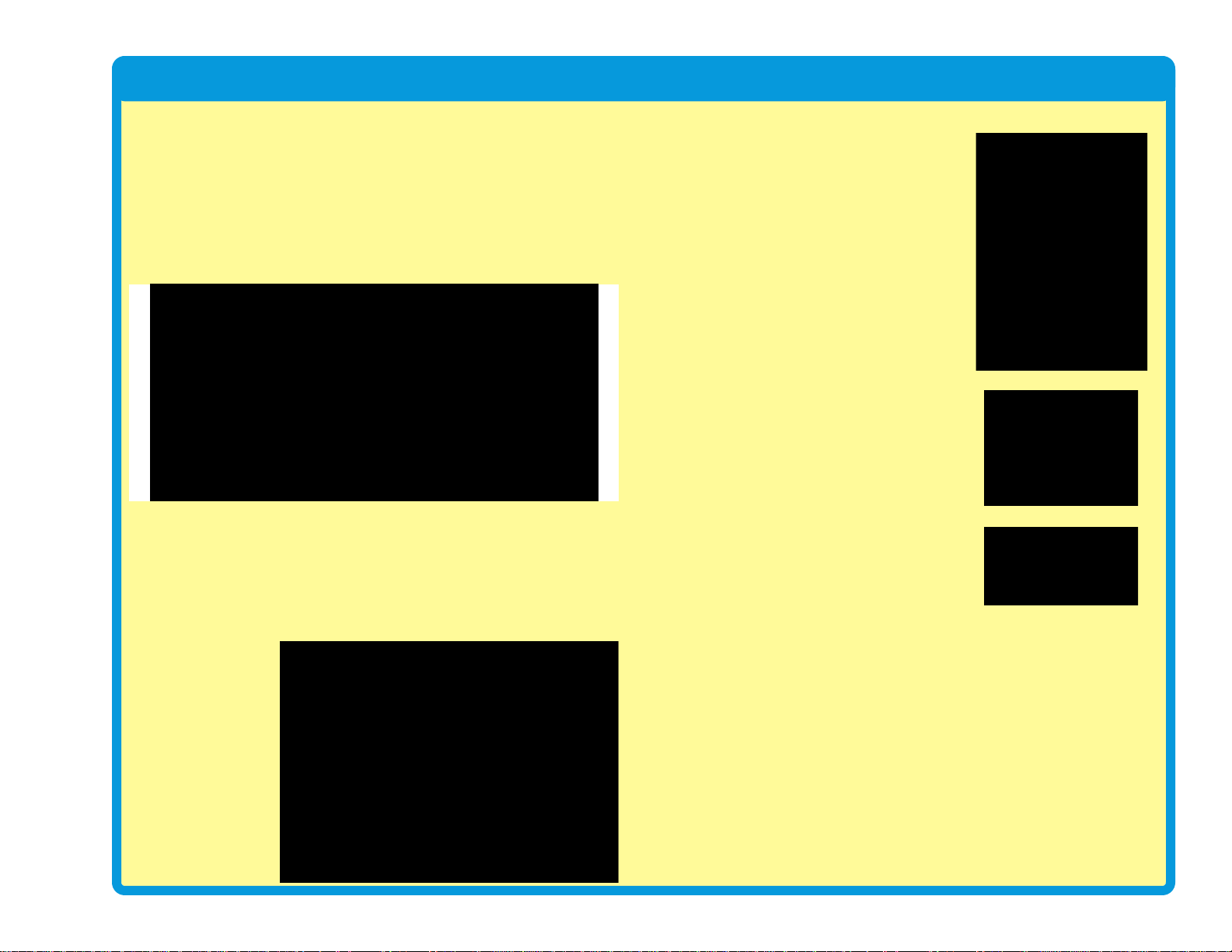
DO’s and DON’Ts of Building Circuits
After building the circuits given in this booklet, you may wish to experiment on your own.
Use the projects in this booklet as a guide, as many important design concepts are
introduced throughout them. Every circuit will include a power source (the batteries), a
resistance (which might be a resistor, capacitor, motor, integrated circuit, etc.), and wiring
paths between them and back.You must be careful not to create “short circuits” (very low-
resistance paths across the batteries
, see examples at right) as this will damage
components and/or quickly drain your batteries. Only connect the color organ (U22), strobe
IC (U23) and infrared module (U24) using configurations given in the projects, incorrectly
doing so may damage them. ELENCO®is not responsible for parts damaged due to
incorrect wiring.
Here are some important guidelines:
ALWAYS
USE EYE PROTECTION WHEN EXPERIMENTING ON YOUR OWN.
ALWAYS
include at least one component that will limit the current through a circuit, such
as the speaker, capacitors, ICs (which must be connected properly), motor,
microphone, phototransistor, or resistors.
ALWAYS
use LEDs, transistors, and switches in conjunction with other components that
will limit the current through them. Failure to do so will create a shor t circuit
and/or damage those parts.
ALWAYS
connect capacitors so that the “+” side gets the higher voltage.
ALWAYS
disconnect your batteries immediately and check your wiring if something
appears to be getting hot.
ALWAYS
check your wiring before turning on a circuit.
ALWAYS
connect the color organ (U22), strobe IC (U23) and infrared module (U24)
using configurations given in the projects or as per the connection description
on page 8.
NEVER
connect to an electrical outlet in your home in any way.
NEVER
leave a circuit unattended when it is turned on.
NEVER
touch the motor when it is spinning at high speed.
For all of the projects given in this book, the parts may be arranged in diff erent wa ys without
changing the circuit. F or example , the order of parts connected in series or in parallel does
not matter — what matters is how combinations of these sub-circuits are arranged together.
Placing a 3-snap wire directly
across the batteries is a
SHORT CIRCUIT.
This is also a
SHORT CIRCUIT.
When the slide switch (S1) is turned on, this large circuit has a SHORT
CIRCUIT path (as shown by the arrows). The short circuit prevents any
other portions of the circuit from ever working.
NEVER
DO!
NEVER
DO!
NEVER
DO!
NEVER
DO!
Examples of SHORT CIRCUITS - NEVER DO THESE!!!
Warning to Snap Circuits®owners: Do not use
parts from other Snap Circuits
®
sets with this kit.
Other sets use higher voltage which could damage
parts.
You are encouraged to tell us about new programs and circuits you
create. If they are unique , we will post them with your name and state
on our website at:
www.snapcircuits.net/learning_center/kids_creation
Send your suggestions to ELENCO
®
: elenco@elenco.com.
ELENCO
®
provides a circuit designer so that you can make y our own
Snap Circuits®drawings. This Microsoft®Word document can be
downloaded from:
www.snapcircuits.net/learning_center/kids_creation
or through the www.snapcircuits.net website.
`
`
_
WARNING: SHOCK HAZARD- Never connect Snap Circuits
®
to the electrical outlets in your home in any way!
`
`
`
Page 15
-14-
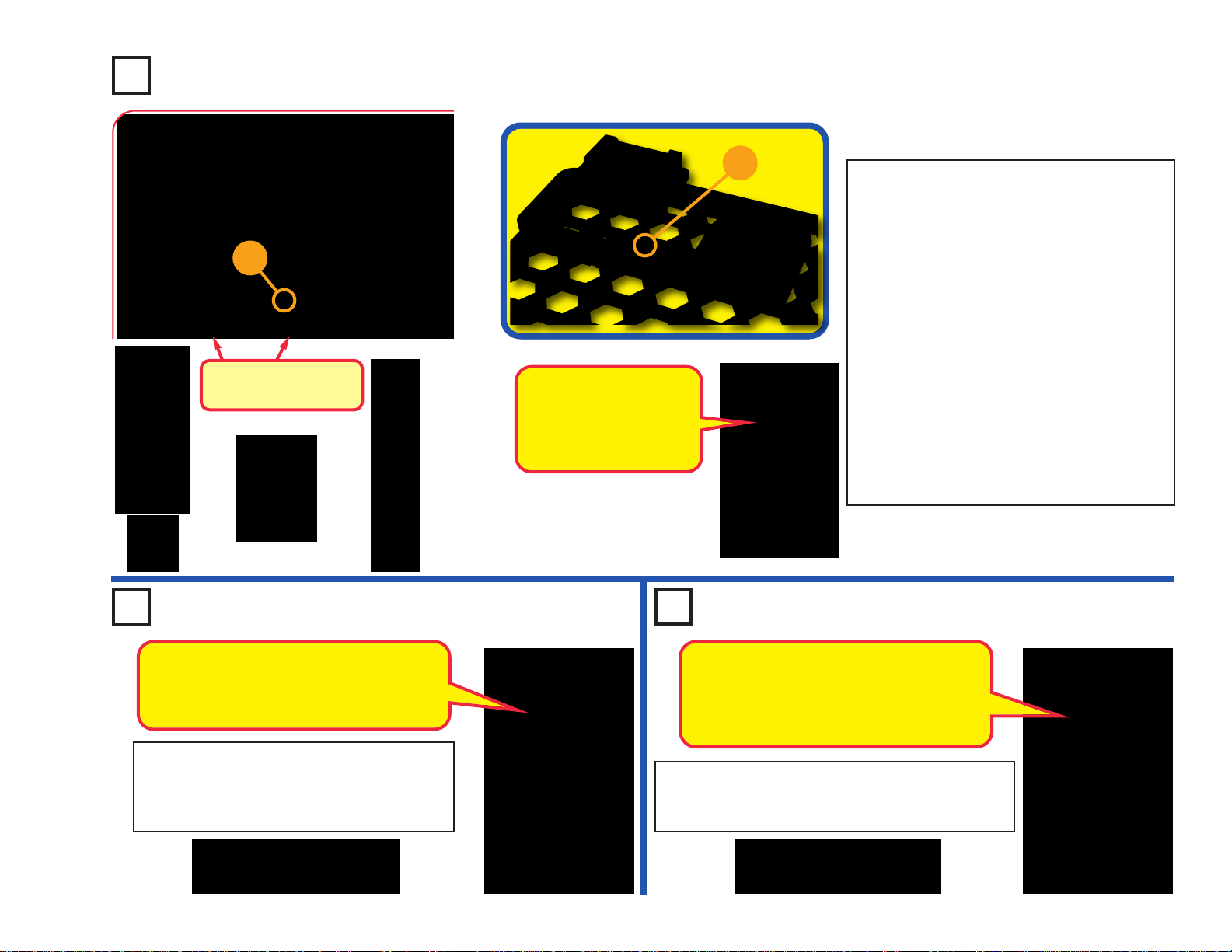
Advanced Troubleshooting
(Adult supervision recommended)
ELENCO®is not responsible for parts
damaged due to incorrect wiring.
If you suspect you have damaged parts,
you can f
ollow this procedure to
systematically determine which ones need
replacing:
(Note: Some of these tests connect an LED
directly across the batteries without another
component to limit the current. Normally this
might damage the LED, however Snap Circuits
®
LEDs have internal resistors added to protect
them from incorrect wiring, and will not be
damaged.)
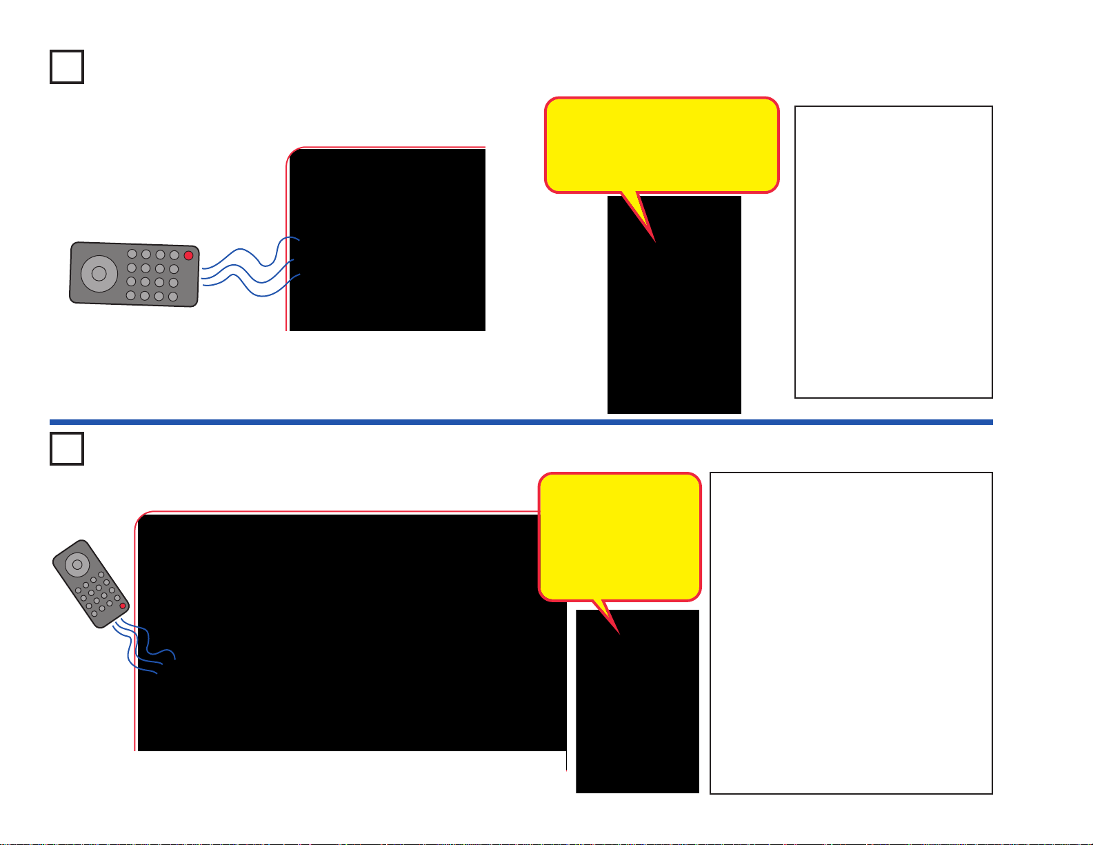
1. Red LED (D1), motor (M1), speaker (SP),
and battery holder (B1): Place batteries in
holder. Place the red LED directly across the
battery holder (LED + to battery +), it should
light. Do the same for the motor, it should
spin. “Tap” the speaker across the battery
holder contacts, you should hear static as it
touches. If none work, then replace your
batteries and repeat. If still bad, then the
battery holder is damaged.
If the motor spins but does not balance the
fan, check the b lac k plastic piece with three
prongs on the motor shaft, and replace it if
it is damaged (this kit includes a spare). To
replace, pry the broken one off the motor
shaft using a screwdriver , then push the new
one on.
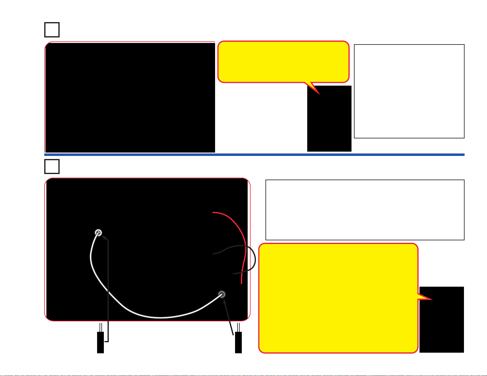
2. Red & black jumper wires: Use this mini-
circuit to test each jumper wire, the LED
should light.
3. Snap wires: Use this mini-circuit to test
each of the snap wires, one at a time
. The
LED should light.
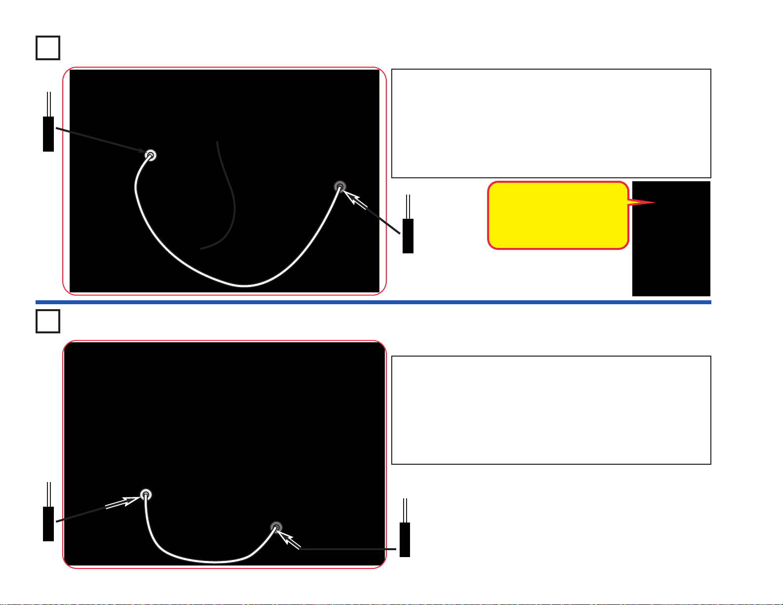
4. Slide switch (S1) and Press switch (S2):
Use this mini-circuit; if the LED doesn’t light
then the slide switch is bad.
Replace the
slide switch
with the press
switch to test it.
5. 100Ω (R1) and 5.1kΩ (R3) resistors: Use
the mini-circuit from test 4 but replace the
s
witch with the 100Ω resistor (R1); the LED
will be bright if the resistor is good. Ne xt use
the 5.1kΩ resistor in place of the 100Ω
resistor; the LED should be much dimmer
but still light.
6. White LED (D6) and color LED (D8): Use
this mini circuit; if the white LED
doesn’t light
then D6 is bad. Replace the white LED with
the color LED; it should change colors in a
repetitive pattern, otherwise D8 is bad.
7. Microphone (X1) and Phototransistor
(Q4): Use the mini-circuit from test 6 but
replace the 100Ω resistor with the
microphone (+ on right);
if blowing into the
microphone does not change the LED
brightness then X1 is bad. Replace the
microphone with the phototransistor (+ on
right). Waving your hand over the
phototransistor (changing the light that
shines on it) should change the brightness
of the LED or Q4 is bad.
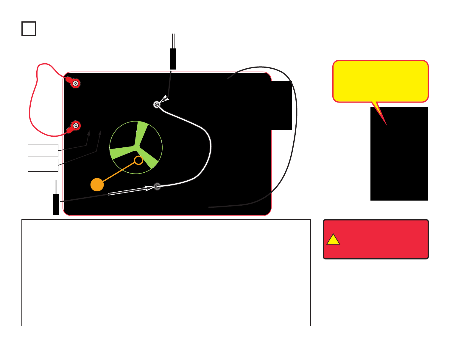
8. Adjustable resistor (RV): Build project
160, but use the red LED (D1) in place of
the color LED (D8).
Move the resistor control
lever to both sides. When set to each side,
one LED should be bright and the other off
(or very dim); otherwise RV is bad.
9. PNP transistor (Q1): Build the mini-circuit
shown here
. The red LED (D1) should only
be on if the press switch (S2) is pressed. If
otherwise, then Q1 is damaged.
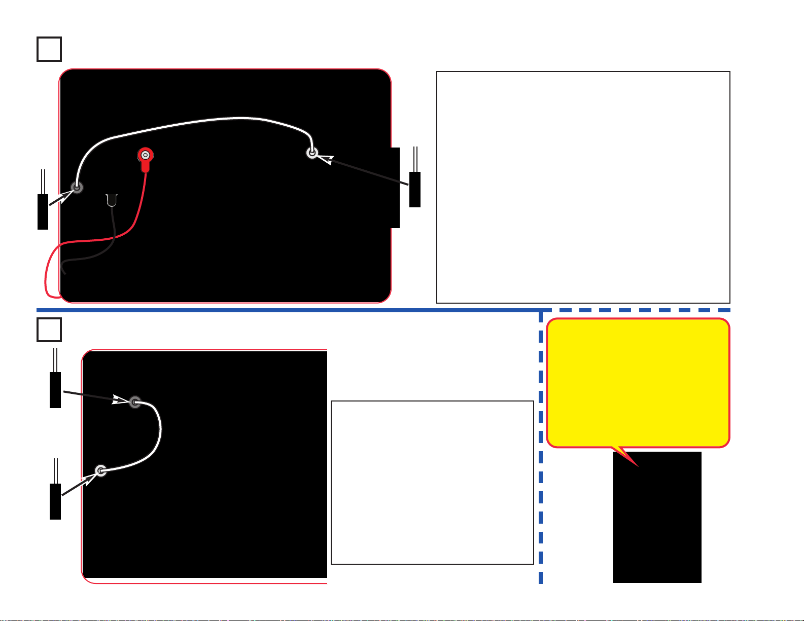
10. NPN transistor (Q2): Build the mini-
circuit shown here
. The red LED (D1)
should only be on if the press switch (S2)
is pressed. If otherwise, then Q2 is
damaged.
Page 16
-15-
Advanced Troubleshooting
(Adult supervision recommended)
11. Strobe IC (U23) and 100kΩ resistor
(R5): Build the mini-circuit shown here,
and turn on the s
witch (S1). The speaker
should make a buzzing sound or U23 is
bad. Next use the 100kΩ resistor in place
of the 5.1kΩ resistor; the sound should be
a beeping sound now or R5 is bad.
12. Infrared module (U24): Build project 41,
the remote control should turn the red LED
(D1) on;
otherwise U24 is bad.
13. 0.1µF capacitor (C2) and 100µF
capacitor (C4): Build this circuit. There
should be a buzzing sound, or C2 is bad.
Ne
xt, replace C2 with C4; now you should
hear beeps every 5 seconds, or C4 is bad.
The setting on RV does not matter.
15. Color organ (U22): Do project 182. If
parts A or B do not work, U22 is damaged.
If part C does not work, then there may be
a problem with U22, with your stereo
cable, with your music device, or you may
not have your music device on the right
settings.
ELENCO
®
150 Carpenter Avenue
Wheeling, IL 60090 U.S.A.
Phone: (847) 541-3800
Fax: (847) 520-0085
e-mail: help@elenco.com
Website: www.elenco.com
You may order additional /
replacement parts at:
www.snapcircuits.net
1
1
1
1
1
1
2
2
2
2
2
2
2
2
3
3
3
1
1
1
1
1
2
2
2
2
2
2
2
Page 17

-16-
Project # Description Page #
1 Color Light 18
2 White Light 18
3 Red Light 18
4 Light Show 19
5 Voice Light Show 20
6 Play the Color Organ 20
7 Flying Saucer 21
8 Super Flying Saucer 21
9 Big Circuit 22
10 Box Cover Circuit 23
11 Blinking Colors 24
12 Fiber Optics 24
13 Tones Over Light 25
14 Color Optic Sounds 25
15 Color Light Transporter 26
16 Color Optics 26
17 High Power Fiber Optics 27
18 High Color Optics Sounds 27
19 Sound Maker 28
20 Strobe Light 28
21 Color Strobe Light 28
22 Red Strobe Light 28
23 Noisy Strobe Light 29
24 Noisy Red Strobe Light 29
25 Double Strobe Light 29
26 Louder Strobe Light 29
27 Louder Color Strobe Light 29
28 Triple Strobe Light 30
29 Noisy Double Strobe Light 30
30 Noisy Triple Strober 30
31 Triple Light Noisy Motion Strober 30
Project # Description Page #
32 Automatic Light 31
33 Color Oscillator 31
34 Dance to the Music 32
35 Super Dance to the Music 32
36 Super Dance to the Music (II) 32
37 Follow the Music 33
38 Color Organ - Headphones 33
39 Adjustable Light Dance 34
40 Suspended Raindrops 34
41 Infrared Detector 35
42 Audio Infrared Detector 35
43 Photo Infrared Detector 36
44 Photo Audio Infrared Detector 36
45
Photo Audio Infrared Detector (II)
36
46 Strobe Effects 37
47 Slow Strobe Effects 37
48 Stable Strobe Effects 38
49 Strobe Effects (II) 38
50 Strobe Effects (III) 38
51 Strobe Effects (IV) 38
52 Strobe Effects (V) 38
53 Strobe Effects (VI) 39
54 Make Your Own Strobe Effects 39
55 Another Strobe Light 39
56 Motor Strobe Effects 40
57 Motor Strobe Effects (II) 40
58 Motor Strobe Effects (III) 40
59 LEDs Together 41
60 LEDs Together (II) 41
61 Brightness Control 42
62 Resistors 42
Project # Description Page #
63 Resistors & LEDs 42
64 Low Power Brightness Control 43
65 Low Power Resistors & LEDs 43
66 Persistence of Vision 43
67 Prismatic Film 44
68 Look at the Lights 44
69 Scattering Light 44
70 Color Fiber Light 44
71 One Way Plastic 45
72 White Blinker 45
73 Red Blinker 45
74 Red & White 45
75 Color Selector - Red 46
76 Color Selector - Green 46
77 Color Selector - Blue 46
78 Color Selector - Cyan 46
79 Color Selector - Yellow 46
80 Color Selector - Purple 46
81 Color Selector - White 46
82 LED Color Spectrum 47
83 LED Color Spectrum (II) 47
84 LED Color Spectrum (III) 47
85 LED Color Spectrum (IV) 47
86 LED Color Spectrum (V) 47
87 Blinking Beeping 48
88 Blinking Blinking 48
89 Blinking Control 48
90 Blinking Control Beeping 48
91 Triple Blinker 49
92 Funny Speed Motor 49
93 Funny Speed Motor with Light 49
Project Listings
Page 18

-17-
Project # Description Page #
94 Light Dance Audio Override 50
95 Light Dance Light Override 50
96 Counting Light 51
97 Adjustable Counting Light 51
98 Bright Off Light 52
99 R/C Blink & Beep 52
100 Stuck On Light 53
101 Stuck On Lights 53
102 White Blinker 53
103 Low Voltage Stuck On Lights 53
104 Stuck On Motor & Lights 53
105 Funky Light & Sound 54
106 Light & Sound 54
107 Light & Motion 54
108 Adjustable Light & Sound 54
109 Adjustable Light & Motion 54
110 Blinking Step Motor 55
111 Blink Step Beep 55
112 Day Blinker 56
113 Night Blinker 56
114 Night Light Show 56
115 Daylight Light Show 56
116 Buzzer 57
117 Higher Pitch Buzzer 57
118 Photo Light & Motion 57
119 Slow Light & Motion 57
120 Light Up the Fan 57
121 High Power Buzzer 58
122 Buzz Fan 58
123 Photo Buzzer 58
124 Step Beeper 58
Project # Description Page #
125 Wacky Buzzer 58
126 Fiber Fun 59
127 Fiber Fun Backwards 59
128 More Fiber Fun 59
129 Other Fiber Fun 59
130 Morse Code 60
131 Fiber Shut-Off 60
132 Blow On Fiber 61
133 Fiber Music 61
134 Fiber Color Organ 62
135 Bright Fiber Color Organ 62
136 Motor Power 63
137 More Motor Power 63
138 Reflection Detector 63
139 Cup & String Communication 64
140 Slow Motor Speed Control 65
141 Slow Motor Start Aid 65
142 R/C Motor 65
143 Series Lights 66
144 Wacky Sound Control 66
145 Musical Shapes 67
146 Human & Liquid Sounds 67
147 Human & Liquid Light 67
148 Blow On the Light 68
149 Blow Off the Light 68
150 Transistor 69
151 Another Transistor 69
152 Charging & Discharging 70
153 Mini Capacitor 70
154
Adjustable Charging & Discharging
70
155 Mini Battery 70
Project # Description Page #
156 Photo Current Amplifier 71
157 LEDs &
Transistors 71
158 PNP Amplifier 71
159 Photo Control 72
160 Resistance Director 72
161 Current Controllers - Series 73
162 Current Controllers - Parallel 73
163 Blow Sound Changer 74
164 Short Light 74
165 Shorter Light 74
166 Photo Light Control 75
167 Air Pressure Light Control 75
168 Slow On, Slower Off 75
169 Delayed Photo Speed Control 76
170 Delayed Speed Control 76
171 Delayed Speed Control (II) 76
172 Audio Delayed Speed Control 76
173 Photo Speed Control 76
174 Light Buzz 77
175 Delay Lights 77
176 Touch Light 78
177 Narrow Range Tone 78
178 Slow Off Lights 78
179 3D Pictures 79, 80
180 Super Infrared Detector 80
181 Infrared Optical Audio 81
182 Test the Color Organ 81
Project Listings
Page 19
-18-
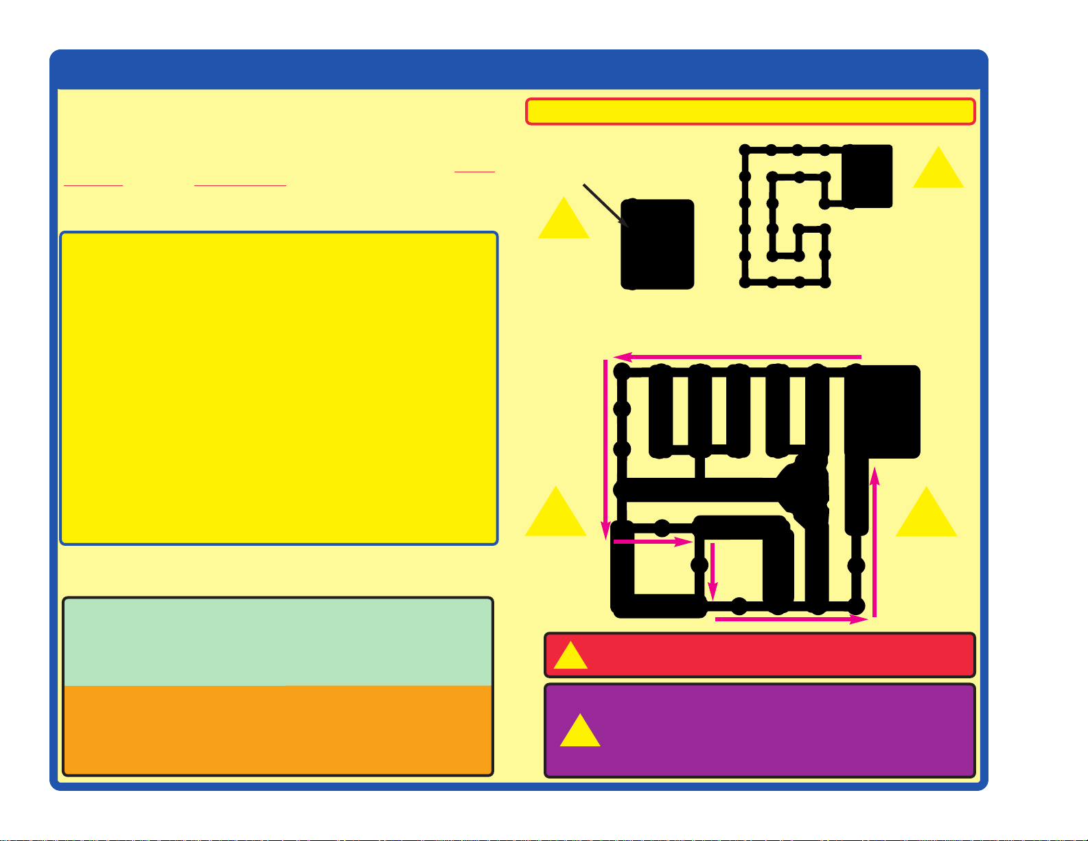
Project 1 Color Light
Snap Circuits®uses electronic blocks that
snap onto a clear plastic grid to build different
circuits. These blocks have different colors
and numbers on them so that you can easily
identify them.
Build the circuit shown on the left by placing
all the parts with a black 1 next to them on the
board first. Then, assemble parts marked with
a 2. Install two (2) “AA” batteries (not
included) into each of the battery holders (B1)
if you have not done so already.
Turn on the slide switch (S1), and enjoy the
light show from the color LED (D8). For best
effects, place one of the LED attachments
(tower, egg, or fiber optic tree) on the color
LED, and dim the room lights. The fiber optic
tree must be used with its mounting base.
+
Use the circuit built in project 1, but replace
the color LED (D8) with the white LED (D6).
Try it with one of the LED attachments, and
in a dark room.
Use the circuit built in project 2, but replace the
white LED (D6) with the red LED (D1). Try it with
one of the LED attachments, and in a dark room.
Project 2 White Light Project 3 Red Light
+
The white LED produces very bright light.
LEDs are this one are increasingly being
used for home lighting and flashlights. They
are more efficient than normal light bulbs.
The red LED is not nearly as bright as the
other LEDs. LEDs like this one are used as
indicators in many products in your home.
They are inexpensive, but don’t produce
much light.
Placement Level
Numbers
Snappy says the color
LED actually contains
separate red, green, and
blue lights, with a microcircuit controlling them.
LED Attachments
Page 20
-19-
Snap Circuits®uses electronic blocks that
snap onto a clear plastic grid to build different
circuits. These bloc ks hav e diff erent colors and
numbers on them so that you can easily
identify them.
Build the circuit shown above b y placing all the
parts with a black 1 next to them on the board
first. Then, assemble parts marked with a 2.
Then, assemble parts marked with a 3. Then,
assemble parts marked with a 4 (just one end
of the red jumper wire, in this circuit). Install
two (2) “AA” batteries (not included) into each
of the battery holders (B1) if you have not
done so already.
If desired, place any of the LED attachments
(tower, egg, or fiber optic tree) on any of the
LEDs (red (D1), color (D8), white (D6), or the
LED on the color organ IC (U22). Note that the
fiber optic tree requires its mounting base.
Turn on slide switch (S1) and enjoy the show!
Project 4 Light Show
+
+
+
Placement Level
Numbers
LED Attachments
All the lights in this set are LEDs - Light
Emitting Diodes. LEDs conv ert electrical
energy into light; the color of the light
emitted depends on the characteristics
of the material used in them.
Page 21
-20-
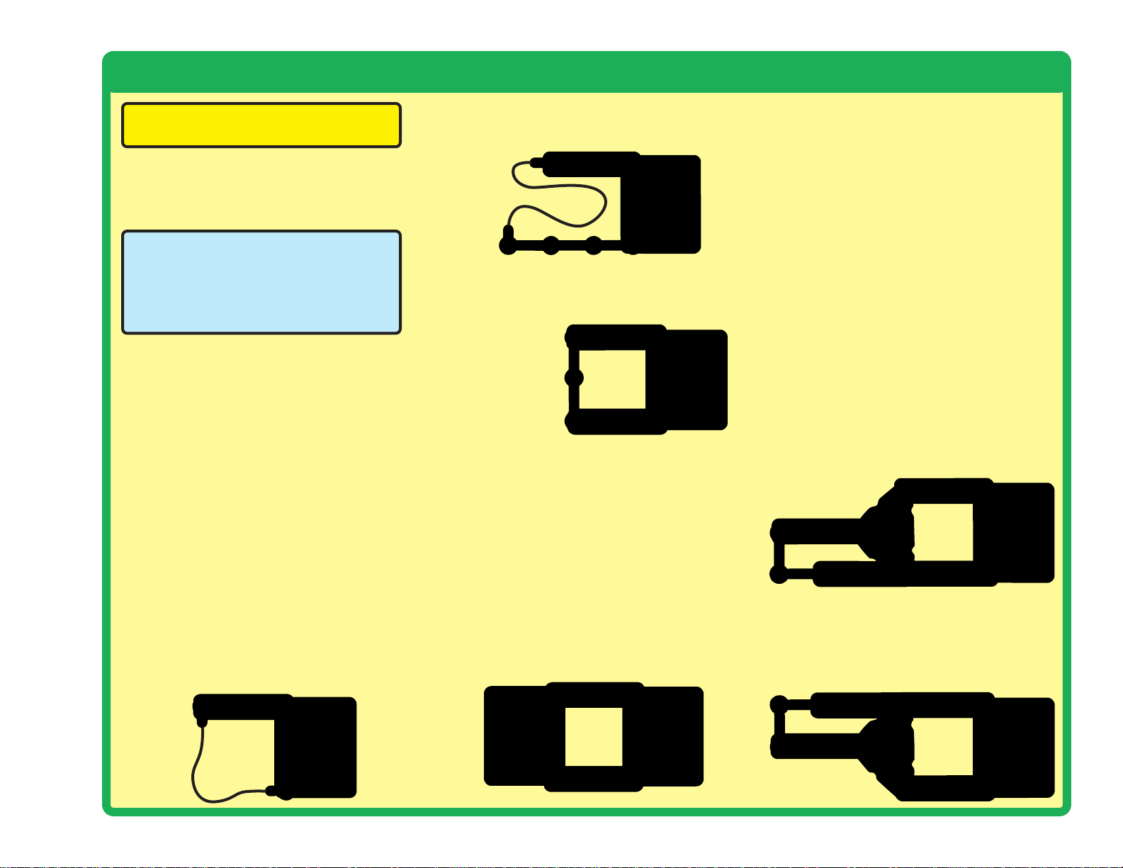
Project 5 Voice Light Show
Project 6 Play the Color Organ
Build the circuit as shown, and place one of the LED attachments (tower,
egg, or fiber optic tree) over the LED on the color organ (U22). Turn on
the switch (S1) and talk. The color organ light will follow your voice, in
tone and loudness.
Build the circuit as shown, and turn on the switch (S1). Place one of the
LED attachments on the color organ (U22). Wet y our fingers, and touch
them between the point marked “X”, and points marked “R”, “G”, or “B”
in the drawing. Try X with every combination of R, G, and B, including
touching them all at the same time.
The light in the color organ module is
actually red, gree
, and blue LEDs together.
The points marked R, G, and B control the
light for those colors. Combining red and
green makes yellow, green and blue makes
cyan, red and blue makes purple, and
combining all three colors makes white.
How does it work? The
microphone converts your
voice to an electrical signal,
which controls an electronic
counter in the color organ.
The counter controls a redgreen-blue LED.
LED
Attachments
LED Attachments
Page 22
-21-
!
WARNING: Moving parts. Do not
touch the fan or motor during operation.
Do not lean over the motor. Fan may
not rise until switch is released.
This circuit will make the fan spin faster and fly higher than the
preceding circuit, making it easy to lose your fan.
WARNING: Elenco
®
Electronics Inc. is not responsible for lost or
broken fans! You may purchase replacement fans at www.
snapcircuits.net.
Push the press switch (S2) until the motor reaches full speed, then
release it. The fan blade should rise and float through the air like a flying
saucer. Be careful not to look directly down on fan blade when it is
spinning.
Project 7 Flying Saucer
Project 8 Super Flying Saucer
Push the press switch (S2) until the motor reaches
full speed, then release it. The fan blade should rise
and float through the air like a flying saucer. Be
careful not to look directly down on fan blade when
it is spinning.
If the fan doesn’t fly off, then press the s witch se ver al
times rapidly when it is at full speed. The motor spins
faster when the batteries are new.
The glow fan will glow in the dark. It will glow best
after absorbing sunlight for a while. The glow fan is
made of plastic, so be careful not to let it get hot
enough to melt. The glow looks best in a dimly lit
room.
+
The air is being blown down through the blade and
the motor rotation locks the fan on the shaft. When
the motor is turned off, the blade unlocks from the
shaft and is free to act as a propeller and fly through
the air. If speed of rotation is too slow, the fan will
remain on the motor shaft because it does not have
enough lift to propel it.
+
!
WARNING: Mo ving parts. Do not touch the fan
or motor during operation. Do not lean o v er the
motor. Fan may not rise until switch is released.
Eye protection is recommended for this circuit.
Page 23
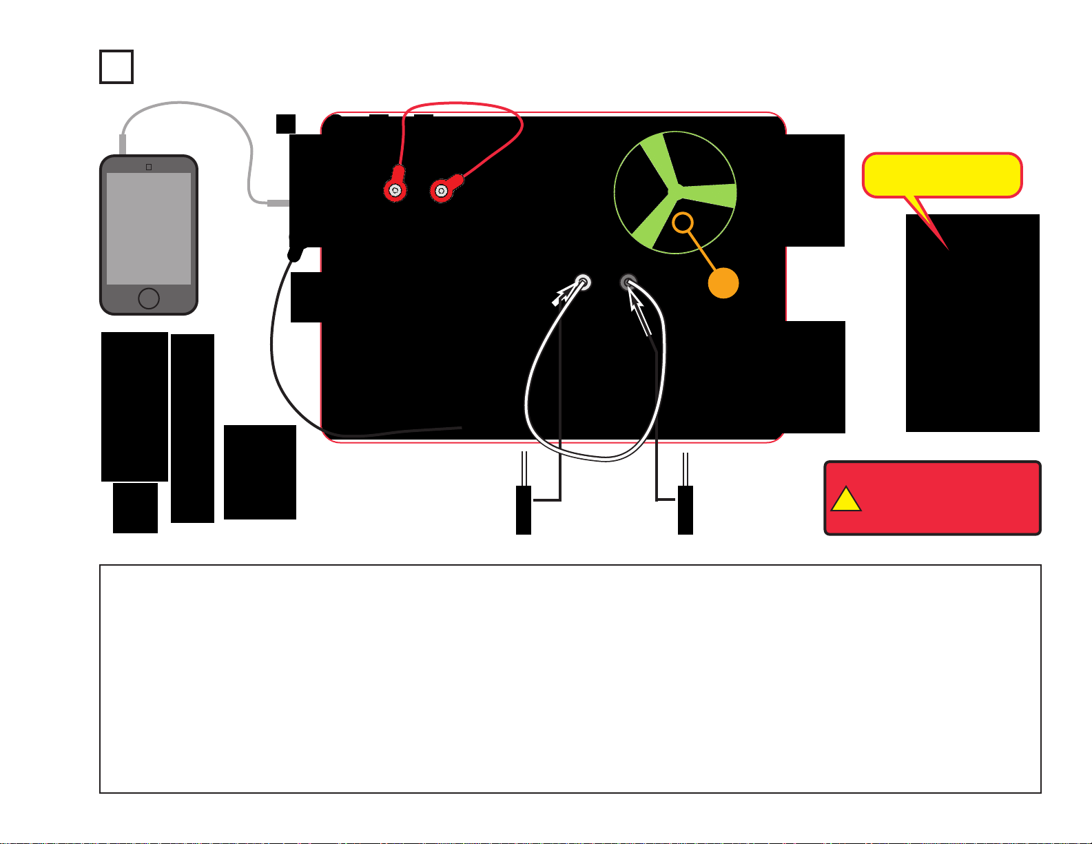
-22-
Build the circuit as shown. Place either the glow fan or the light fan on
the motor (M1) shaft, so that it is stable on the little black piece. Place
the clear fiber optic holder on the color LED (D8) and the black fiber optic
holder on the phototransistor (Q4), then insert the fiber optic cable
between them, but don’t let it lay close to the fan on the motor. For best
performance the fiber optic cable should stand straight up in the holders,
without bending them. Connect a music device to the color organ (U22)
as shown, and start music on it. For best effects, place one of the LED
attachments over the light on the color organ.
Turn on slide switch (S1). Adjust the le ver on the adjustab le resistor (R V)
and the volume control on your music device for best sound and light
effects.
Push the press switch (S2) until the motor reaches full speed, then
release it. The fan will rise into the air like a flying saucer. Be careful not
to look down on the fan when it is spinning. If desired, connect the light
fan blade to the charger f or a while to charge it, then place it on the motor
to spin or launch it.
“Playing the Color Organ”: turn off or disconnect your music device. W et
your fingers, and touch them between the point marked “X”, and “R”, “G”,
or “B” in the drawing.
The infrared detector (U24) and 100kΩ resistor (R5) are only used to
support the other components.
!
WARNING: Moving parts.
Do not touch the fan or
motor during operation. Do
not lean over the motor.
Project 9 Big Circuit
+
This circuit does a lot of
different things at once.
MP3
player
LED Attachments
Black
Clear
Page 24
-23-
!
WARNING: Moving parts. Do
not touch the fan or motor
during operation. Do not lean
over the motor . Fan may not rise
until switch is released.
Build the circuit as shown. Place the glow fan on the motor (M1) shaft, so that it is stable on the little black
piece. Place the clear fiber optic holder on the white LED (D6) and the black fiber optic holder on the
phototransistor (Q4), then insert the fiber optic cable between them, but don’t let it lay close to the fan on
the motor. For best performance the fiber optic cable should stand straight up in the holders, without bending
them. For best effects, place one of the LED attachments over the light on the color organ, and one on the
color LED (D8).
Optional: connect a music device to the color organ (U22) as shown, and start music on it (the color organ
light will change to the music, but you will not hear it unless you also connect headphones).
Turn on slide switch (S1). A tone is hear from the speaker (SP), and all the lights (D1, D6, D8, and on U22)
are on.
Push the press switch (S2) until the motor reaches full speed, then release it. The fan will rise into the air
like a flying saucer. Be careful not to look down on the fan when it is spinning.
Project 10 Box Cover Circuit
Headphones
(optional)
Music device
(optional)
This circuit is called the Box Cov er
Circuit because it is pictured on
the front of the Snap Circuits
®
LIGHT box, use that picture to
help in building it.
+
Black
Clear
Page 25
-24-
Build the circuit as shown. Place the clear cable holder on the red LED (D1)
and the black cable holder on the phototr ansistor (Q4), then place the fiber
optic cable into the holders as far as it will go. For best performance the
cable should stand straight up in the holders, without bending them.
Turn on slide switch (S1) and move the lever on the adjustable resistor
(RV) around. The sound from the speaker (SP) changes as you move
the lever on RV.
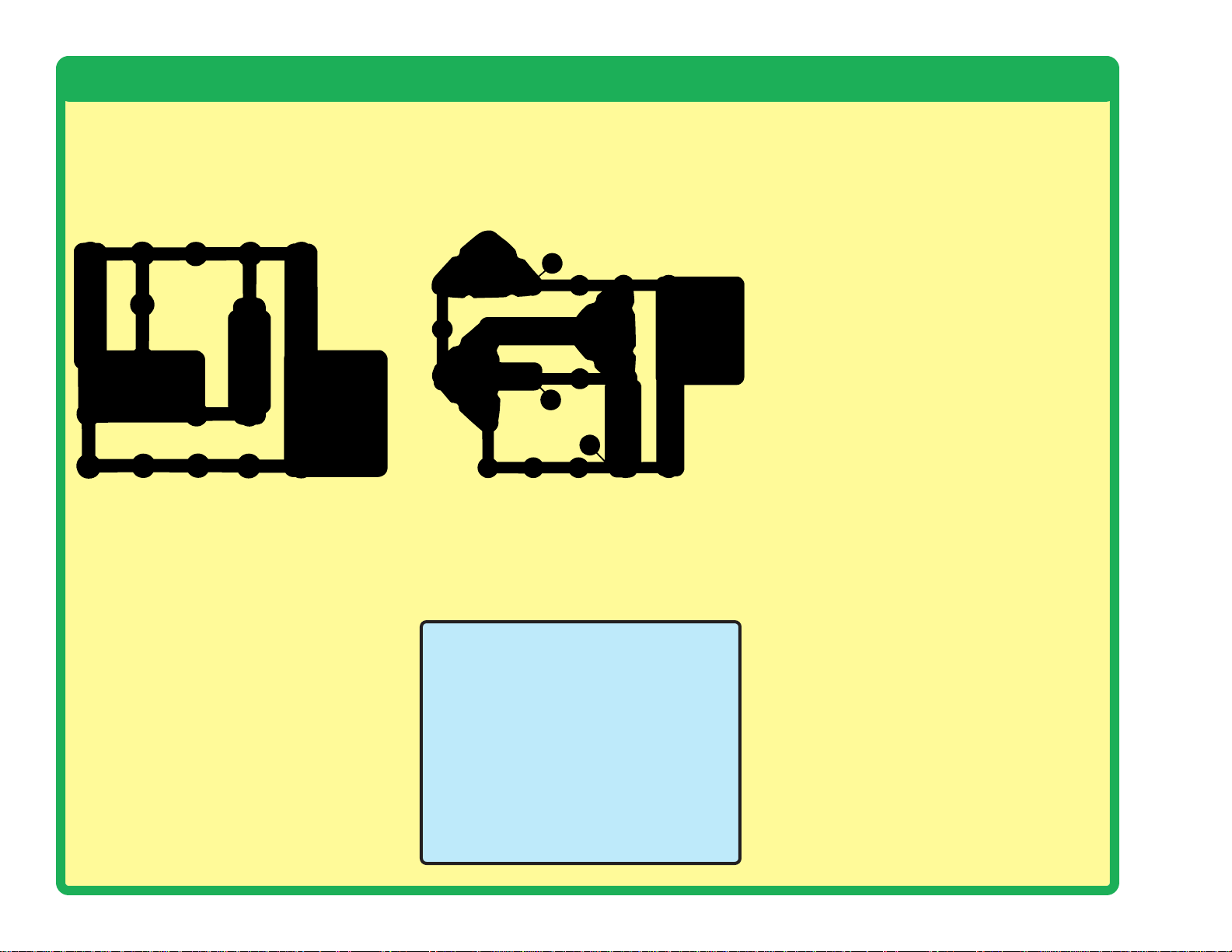
Project 11 Blinking Colors
Build the circuit as shown and turn on
the slide switch (S1). The white and
color LEDs (D6 & D8) are blinking.
Push the press switch (S2). Now the
red LED (D1) is blinking but the white
LED is off.
If you swap the locations of the red
and white LEDs, then the red LED will
be blinking and the white LED will be
off, and pushing the press switch
won’t change anything.
Red light is easier for LEDs to produce than
white light. When the red and white LEDs are
connected in parallel (which happens when S2
is pressed), the red LED will dominate because
it turns on more easily.
Fiber Optics Project 12
Black
Clear
This project is more exciting than it looks. The tone sounds
produced by the strobe IC (U23) are played on the speaker (SP),
even though there is no electrical connection between them.
The left half the circuit makes a coded light signal, which you
see in the red LED (D1). The right half of the circuit decodes the
light signal and plays it on the speaker. The fiber optic cable is
used to transmit the light signal between the two sides of the
circuit. There is no electrical connection between the left and
right halves of the circuit, only a light connection using fiber
optics! If your fiber optic cable was longer, the two halves of the
circuit could be many miles apart.
This circuit is an example of using fiber optic cables for
communication. Fiber optics allo ws information to be transmitted
across great distances at very high speeds with very low
distortion, by using light.
Page 26
-25-
Project 13 Tones Over Light
Project 14 Color Optic Sounds
Build the circuit as shown. Place the clear cab le holder on the red LED
(D1) and the black cable holder on the phototr ansistor (Q4), then place
the fiber optic cable into the holders as far as it will go. For best
performance the fiber optic cable should stand straight up in the
holders, without bending them.
Turn on the slide switch (S1) and move the lever on the adjustable
resistor (RV) around. The sound from the speaker (SP) changes as you
move the lever on RV.
Build the circuit as shown. Place the clear cable holder on the color LED
(D8) and the black cable holder on the phototr ansistor (Q4), then place
the fiber optic cable into the holders as far as it will go. For best
performance the fiber optic cable should stand straight up in the
holders, without bending them.
Turn on the slide switch (S1) and push the press switch (S2). Light is
transmitted from the color LED , through the fiber optic cable, to control
the strobe IC (U23) and speaker (SP).
This is similar to project 12 but
not as loud. The project 12
circuit uses a two-transistor
amplifier while this circuit only
has one transistor.
Black
Clear
Clear
Black
Page 27

-26-
Project 15
Color Light Transporter
Project 16 Color Optics
Build the circuit as shown. Place the clear cable
holder on the color LED (D8) and the black cable
holder on the phototransistor (Q4), then place the
fiber optic cable into the holders as far as it will go . F or
best performance the fiber optic cable should stand
straight up in the holders, without bending them.
Turn on the switch (S1). The color LED (D8) turns on
and off repeatedly as it changes colors. This produces
interesting effects when connected to the speaker
circuit through the fiber optic cable.
Build the circuit as shown. Place the black cable holder on the color
LED (D8), then place the fiber optic cable into the holder as far as it will
go. For best performance the fiber optic cable should stand straight up
in the holder, without bending it. Leave the other end of the cable free.
Turn on the switch (S1), and look into the loose end of the fiber optic
cable. Flex the cable into loops but don’t dent it. Take the circuit into a
dark room and see how the cable looks.
You can use the clear cable holder on the color LED instead of the black
holder.
Light can travel through
fiber optic cables over
great distances, even
through bends and
curves.
Black
Clear
Black
Page 28
-27-
Project 17
High Power Fiber Optics
Project 18
Build the circuit as shown. Place the clear cable holder on the
white LED (D6) and the black cable holder on the phototransistor
(Q4), then place the fiber optic cable into the holders as far as it
will go. For best performance the fiber optic cable should stand
straight up in the holders, without bending them.
Turn on the slide switch (S1) and move the lever on the
adjustable resistor (RV) around. The sound from the speaker
(SP) changes as you move the lever on RV.
Try removing the black cable holder and just holding the fiber
optic cable next to the phototransistor with your fingers. Hold it
at different angles and compare the sound. You may not hear
anything, due to background light in the room. Take the circuit
into a dark room or place your fingers around the
phototransistor to block the room light to it. Now put the black
cable holder back on, remove the clear cable holder, and try
holding the fiber optic cable at different positions around the
white LED . You can also replace the white LED with the red LED
(D1) or the color LED (D8).
High Color
Optics Sounds
Build the circuit as shown. Place the clear
cable holder on the color LED (D8) and the
black cable holder on the phototransistor
(Q4), then place the fiber optic cable into
the holders as far as it will go. For best
performance the fiber optic cable should
stand straight up in the holders, without
bending them.
Turn on the slide switch (S1). Light is
transmitted from the color LED, through
the fiber optic cable, to control the strobe
IC (U23) and speaker (SP).
Black
Clear
The circuits on this page are similar to
projects 12 and 14, but have the fiber
optic transmitting sub-circuit (with the
LED) and the receiving sub-circuit (with
the phototransistor) using the same
voltage sources. Normally the
transmitting and receiving circuits will
be in different locations with separate
voltage sources, but they were
combined here to increase the power.
Black
Clear
Page 29

-28-
Project 19 Sound Maker
Build the circuit and turn on the
switch (S1). You hear sound from
the speaker. Adjust the sound
using the lever on the adjustable
resistor (RV), and b y pushing the
press switch (S2).
Note: In rare cases the circuit
may not work at all settings on
RV. If this happens, move the RV
lever to the side near the strobe
IC, turn the slide switch off and
on to reset the circuit, and only
move the RV lever over a small
range.
The strobe IC (U23) produces an electrical
“tone”. The pitch of the “tone” is adjusted by
changing how much electricity flows into its
upper-left snap, using a resistor. The electrical
tone it produces can be used to make sound
using a speaker, or to control the flash rate of
an LED see project 20, the Strobe Light).
Project 20
Strobe Light
Use the preceding circuit, but replace the
speaker with the white LED (D6). Now you
have a strobe light!
When S2 is pressed, the light may be blinking
so fast that it appears to be on continuously.
Project 21
Color Strobe
Light
Use the preceding circuit, but replace the
white LED with the color LED (D8).
Project 22
Red Strobe
Light
Use the preceding circuit but replace the color
LED (D8) with the red LED (D1).
The color LED will not be
changing colors like it does in
other circuits. When the strobe
IC (U23) turns the color LED
on and off, it resets the colorcontrol microcircuit in the color
LED . Even your slowest strobe
speed is too fast for the color
LED.
Page 30

-29-
Project 23 Noisy Strobe Light
Project 26 Louder Strobe Light
Modify the project 19 circuit to be
this one, which has the white LED
(D6) next to the speaker (SP). Build
the circuit and turn on the switch
(S1). Adjust the b link rate and sound
using the lever on the adjustable
resistor (RV), and by pushing the
press switch (S2).
Note: In rare cases the circuit may
not work at all settings on RV. If this
happens, move the RV lever to the
side near the strobe IC, turn the
slide switch off and on to reset the
circuit, and only move the RV lever
over a small range.
Project 24
Noisy Red
Strobe Light
Use the preceding circuit but replace the
white LED (D6) with the red LED (D1) or
the color LED (D8).
Project 25
Double
Strobe Light
Use the preceding circuit but replace the
speaker and LED with any two LEDs (red,
white, or color).
Project 27
Louder Color
Strobe Light
Use the preceding circuit but
replace the white LED (D6)
with the red LED (D1) or the
color LED (D8).
Modify the preceding circuit to be this one, which
has the white LED (D6) in parallel with the speaker
(SP). Build the circuit and turn on the switch (S1).
Adjust the blink rate and sound using the lever on
the adjustable resistor (RV), and by pushing the
press switch (S2).
This circuit is louder
than the previous
circuits because the
speaker is in parallel
with the LED instead of
in series with it. This
increases the voltage
across the speaker,
making it louder.
Page 31

-30-
Project 28 Triple Strobe Light
Build this circuit and turn on the slide
switch (S1). Adjust the blink rate
using the lever on the adjustable
resistor (RV), and by pushing the
press switch (S2).
Note: In rare cases the circuit may
not work at all settings on RV. If this
happens, move the RV lever to the
side near the strobe IC, turn the slide
switch off and on to reset the circuit,
and only move the RV lever over a
small range.
Project 30
Noisy Triple Strober
Build this circuit and turn on
the slide switch (S1). Adjust
the blink rate and sound using
the lever on the adjustable
resistor (RV), and by pushing
the press switch (S2).
Note: In rare cases the circuit
may not work at all settings on
RV. If this happens, move the
RV lever to the side near the
strobe IC, turn the slide switch
off and on to reset the circuit,
and only move the RV lever
over a small range.
Project 31
Triple Light Noisy
Motion Strober
Project 29
Noisy Double
Strobe Light
Use the preceding circuit but replace one
of the LEDs (D1, D6, or D8) with the
speaker (SP).
!
WARNING: Moving parts. Do not
touch the fan or motor during operation.
Use the preceding circuit but replace the
speaker (SP) with the motor (M1, “+” toward
white LED), then place the speaker across
the points marked A & B in the drawing. Do
not place any fan on the motor.
The LEDs (D1, D6, & D8) flash, the speaker
makes noise, and the motor shaft spins or
wiggles. Adjust the blink rate, sound, and
motor spin using the lever on the adjustable
resistor (RV), and by pushing the press
switch (S2).
Page 32

-31-
Project 32 Automatic Light
Project 33 Color Oscillator
Build the circuit as shown, and
place one of the LED
attachments (tower , egg, or fiber
optic tree) over the LED on the
Color Organ (U22). Tur n on the
switch (S1) and watch. The color
organ light will change colors on
its own.
Build the circuit and turn on the slide switch (S1). Set the lever on the
adjustable resistor (RV) so the white LED (D6) just tur ns off. Slowly
cover the phototransistor (Q4) and the white LED brightens. Adjust the
light to the phototransistor to turn the white LED on or off.
This is an automatic street lamp that you can turn on at a certain
darkness and turn off by a certain br ightness. This type of circuit is
installed on many outside lights and forces them to turn off and save
electricity. They also come on when needed for safety.
You can replace the white LED with the color LED (D8) or the red LED
(D1), but you ma y need to readjust the sensitivity using the lev er on R V.
This circuit is an oscillator;
it uses the color organ to
control itself.
LED
Attachments
Page 33

-32-
Project 34 Dance to the Music
Project 35
Super Dance to the Music
Build the circuit. Connect a
music device (not
included) to the color
organ (U22) as shown,
and start music on it.
Place one of the LED
attachments over the light
on the color organ. Set the
lever on the adjustable
resistor (RV), and the
volume control on your
music device, for best
sound quality and light
effects. The color organ
light will “dance” in synch
with the music. Compare
fast and slow songs, and
different loudness levels.
MP3
player
MP3
player
This circuit is similar to the preceding one,
but louder and more sensitive. Build the
circuit as shown. Connect a music device
(not included) to the color organ (U22) as
shown, and start music on it, set the
volume to mid-range. Place one of the LED
attachments over the light on the color
organ. Turn on the switch (S1) and
SLOWLY ADJUST the lever on the
adjustable resistor (RV) for best sound;
there will only be a narrow range where the
sound is clear. Adjust the volume on your
music device for best sound quality.
Project 36
Super
Dance
to the
Music (II)
Use the preceding circuit,
but remove the 100µF
capacitor (C4). The sound
will not be as loud, but will
be less distorted. Adjust
RV and the v olume on your
music deice for best
sound.
LED
Attachments
This circuit amplifies the
music so it can be heard
on the speaker. This is a
simple circuit, so sound
quality may not be as good
as your other music
players.
LED
Attachments
Page 34

-33-
Project 37 Follow the Music
Project 38
Color Organ - Headphones
Build the circuit. Connect a music device (not
included) to the color organ (U22) as shown, and
start music on it. For best eff ects, place one of the
LED attachments over the light on the color
organ. Set the volume control on your music
device for best sound quality and light eff ects. The
color organ light will “dance” in synch with the
music. Compare fast and slow songs, and
different loudness levels.
MP3
player
Build the circuit. Connect a m usic device (not
included) and your own headphones (not
included) to the color organ (U22) as shown,
and start music on it. For best effects, place
one of the LED attachments over the light on
the color organ. Set the volume control on
your music device f or best sound quality and
light effects. The color organ light will “dance”
in synch with the music.
Output signal to headphones is mono, so you
will not hear stereo effects.
Compare the sound quality
of using headphones in this
circuit, to using the speaker
in the preceding circuit.
MP3
player
Headphones
LED
Attachments
Page 35

-34-
Project 39
Adjustable Light Dance
Project 40 Suspended Raindrops
Build the circuit as shown. For best effects, place one of the LED
attachments over the light on the color organ. Turn on the switch (S1)
and move the lever on the adjustable resistor (RV) to change the tone
of the sound and “speed” of the light.
Build the circuit as shown. Connect the white LED (D6) to the red &
black jumper wires. Turn on the slide switch (S1). Go to a water faucet
and adjust the faucet so water is dripping at a steady rate. Dim the room
lights and hold the white LED so it shines on the dripping water. Try to
set the lever on the adjustable resistor (RV) so that the dipping water
drops appear suspended in mid-air. You may need to adjust the drip
rate on the faucet to make this work. You may get better results if you
replace the 100kΩ resistor (R5) with the 5.1kΩ resistor (R3). Also, try
setting the strobe rate to minimum and adjusting the drip rate.
Faucet
LED
Attachments
Page 36
-35-
Project 41 Infrared Detector
Project 42
Audio Infrared Detector
You need an infrared remote control for this
project, such as any TV/stereo/DVD remote
control in your home.
Build the circuit, set the lever on the adjustab le
resistor (RV) all the way towards the infrared
module (U24), and turn on the switch (S1).
Point your remote control toward the infrared
module and press any button to activate an
alarm sound. The lever on the adjustable
resistor sets how long the alarm plays for, but
it only works over a narrow range.
Next, replace the 100Ω resistor (R1) with the
5.1kΩ resistor (R3). The alarm sound is a little
different, but the control range on RV is wider.
Sometimes this circuit may activate without
a remote control, due to infrared in sunlight
or some room lights. If this happens, try
moving to a dark room.
Remote
You need an infrared remote
control for this project, such
as any TV/stereo/DVD
remote control in your home.
Build the circuit and turn on
the switch (S1). Point your
remote control toward the
infrared module (U24) and
press any button to activate
the red LED (D1).
Sometimes this circuit may
activate without a remote
control, due to infrared in
sunlight or some room lights.
If this happens, try moving to
a dark room.
TV remote controls transmit a
sequence of pulses representing the
TV model and the b
utton that was
pressed. The U24 infrared detector
is just looking any infrared signal.
Remote
Sunlight and other light
sources emit some
infrared light, and may
activate the infrared
detector. See if you can
activate it without a
remote control.
Page 37
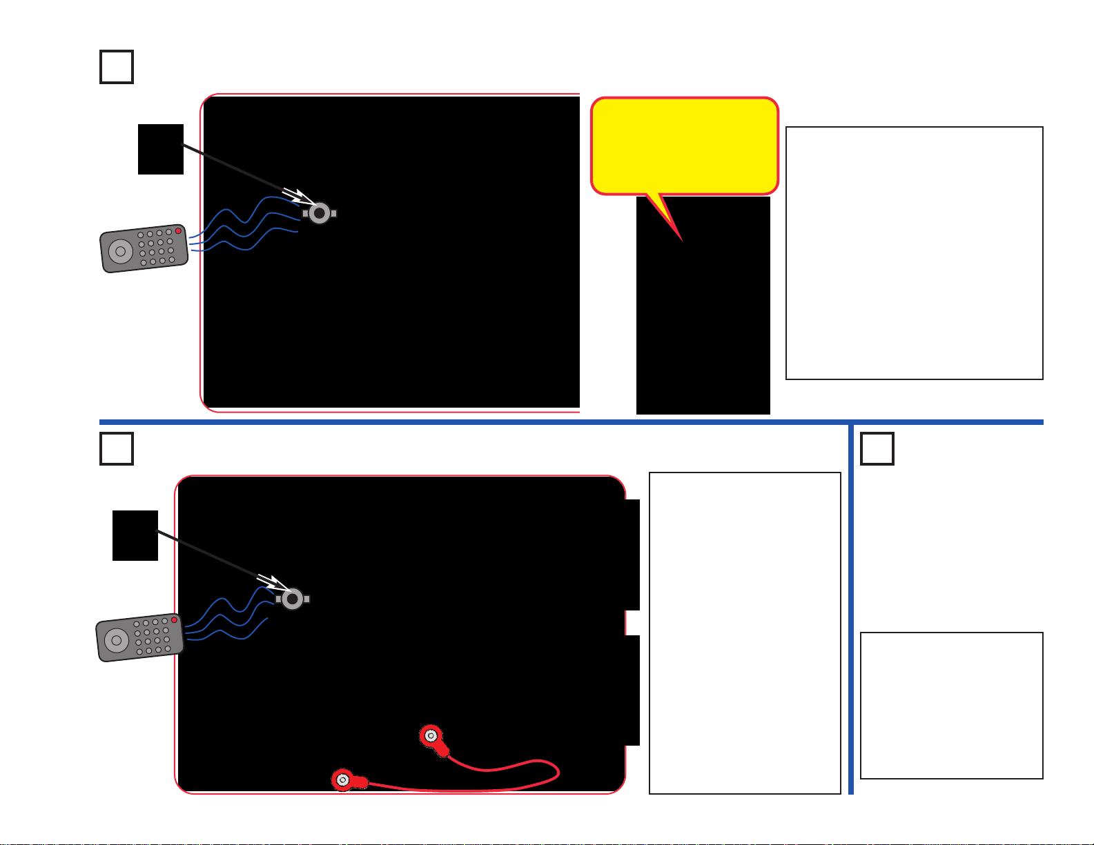
-36-
Project 43
Photo Infrared Detector
Project 44
Photo Audio Infrared Detector
Project 45
Photo Audio
Infrared
Detector
(II)
Use the preceding circuit,
but replace the 0.1µF
capacitor (C2) with the
100µF capacitor (C4). The
circuit works the same way,
but the sound stays on
longer and is more
pleasant.
You need an infrared remote
control for this project, such
as any TV/stereo/DVD
remote control in your home.
Build the circuit and turn on
the switch (S1). Place the
mounting base (normally
used with the fiber optic tree)
on the phototransistor (Q4).
Set the lever on the
adjustable resistor (RV) so
the sound just turns off (if it
never turns off, move away
from room lights. Point your
remote control directly into
the mounting base on Q4,
and press any button to
activate the sound.
Remote
Remote
You need an infrared remote control for
this project, such as any TV/stereo/DVD
remote control in your home.
Build the circuit and turn on the switch
(S1). Place the mounting base
(normally used with the fiber optic tree)
on the phototransistor (Q4). Set the
lever on the adjustable resistor (RV) so
the red LED (D1) just turns off; if it
never turns off, move away from room
lights. P oint your remote control directly
into the mounting base on Q4, and
press any button to activate the red
LED (D1).
The phototransistor can
detect light, and infrared
light is light. The infrared
module (U24) is designed to
focus only on infrared light.
Page 38

-37-
Use the preceding circuit, but replace the 3-snap on the
adjustable resistor (RV) with the 100kΩ resistor (R5). The
circuit works the same, but the strobe rate is much slow er
(now you can see the LED flashing), so the strobe effects
are different. Slowly adjust the setting on RV as before,
and watch the patterns on the spinning disc.
Note: In rare cases the LED ma y not flash at all settings
on RV. If this happens, mov e the R V le ver to the side near
the strobe IC, turn the slide switch off and on to reset the
circuit, and only move the RV lever over a small range.
Bonus for owners of other Snap Circuits
®
sets: If you
have a second 100kΩ resistor (from model SC-100 / 300
/ 500 / 750 or other sets), place it directly over the R5
that replaced the 3-snap in the above circuit (and place
a 1-snap under one side of the additional R5). Stacking
the two 100kΩ resistors together creates a “medium”
range of strobe speeds, in between the speeds created
with the 3-snap and single 100kΩ. Adjust the RV setting
and watch the strobe effects as before.
Project 46 Strobe Effects
Build the circuit as shown. Take the colored disc shown and install it into the disc holder,
then place the disc holder on the motor (M1). Connect the white LED (D6) to the red &
black jumper wires.
For best effects , do this in a dimly lit room. Turn on the slide switch (S1). Push the press
switch (S2) until the motor spins continuously (if it stops after you release the press
switch, replace your batteries). Hold the white LED upside down over the disc holder so
it shines on the spinning disc, and move the lever on the adjustable resistor (RV) slowly
while watching the pattern on the spinning disc.
The motor spins the disc so fast that it looks like a blur. However, as you slowly adjust
RV the pattern on the disc appears to slow down, stop, and reverse direction. Patter ns
close to the disc center may be moving at diff erent speeds, or in diff erent directions, from
patterns farther from the center! Some patterns may become clear while others are still
blurred.
If the motor does not continue spinning after you release S2, then replace your batteries. If
it still won’t keep spinning then replace the 5.1kΩ resistor (R3) with a 3-snap wire.
Project 47
Slow Strobe
Eff
ects
Tab
Slide tabs into slots.
Tab Tab
Place disc holder onto
the motor as shown.
Hold white LED (D6)
over disc as shown.
How does this work? The strobe IC is making the
white LED flash so fast that your eyes think it is on
continuously. RV sets the flash rate, and at some
settings the LED flashes are synchronized with
speed of the patterns spinning on the disc, making
them appear visible instead of blurred.
When the disc pattern is totally blurred, it will appear
as purple, orange, and light green. Combining equal
amounts of red & blue makes purple, red & yellow
makes orange, and yellow & blue makes green.
OPTIONAL
(Adult supervision required)
The disc holder rests on the motor top
loosely and vibrates, making the disc
pattern blurry even when the RV setting
makes the pattern “stop”. The disc
patterns will appear clearer if you
permanently mount the disc holder to the
motor top. This set contains a spare
motor top, which can be used for this.
This requires removing the motor top
from the motor whenever you want to
switch from using the disc holder to using
the glow fan, so is optional, and requires
adult supervision.
If you want to do
this, pry the motor
top off the motor
shaft using a
screwdriver.
Lay the spare motor
top in the disc holder
upside down, and bond
together with glue (glue
not included).
After the glue dries,
push the modified
disc holder on the
motor shaft and
install a disc cutout.
When you want to
return to using the
glow fan, replace the motor top disc
holder with the normal motor top.
Page 39

-38-
Project 50
Strobe Effects (III)
Replace the disc in the disc holder with the
one shown here, and repeat projects 46-48.
Observe the strobe effects. At some RV
settings, the rainbow of colors comes into
view.
Project 51
Strobe Effects (IV)
Project 52
Strobe Effects (V)
Project 48
Stable Strobe Effects
Use the circuits from projects 46 and 47,
but add the 0.1µF capacitor (C2) next to
the motor, as shown here . Set the strobe
speed so the patterns are visible, and
see if they look less blurred than bef ore.
The 0.1µF capacitor has no electrical
effect,but it helps to hold the motor in place
better and reduce vibrations. Less motor
vibration makes the disc holder more
stable, and so makes the patterns a little
clearer. See if you can notice a difference.
Project 49
Strobe Effects (II)
Replace the disc in the disc holder with the one
shown here, and repeat projects 46-48. Observe
the strobe effects. To remove a disc from the
holder, use y our fingernail, or use a pencil to push
it up from beneath one of the tabs.
When the disc pattern is totally blurred,
it appears to be white. Combining equal
amounts of red, green, and blue makes
white. The LED in the color organ IC
combines red, green, and blue lights to
make white.
Replace the disc in the disc holder with the
one shown here, and repeat projects 46-48.
Observe the strobe effects. With this pattern,
some areas may appear to be moving at
different speeds or directions. Sometimes you
can see all the colors on the disc, but
sometimes you can see all the colors except
blue, which is hidden.
Replace the disc in the disc holder with the
one shown here, and repeat projects 46-48.
Observe the strobe effects. This unusual
pattern produces several amazing displays at
different RV settings.
Page 40

-39-
This circuit is similar to project 46, and works the same way. Build the
circuit as shown. Take one of the colored discs and install it into the disc
holder, then place the disc holder on the motor (M1). Connect the white
LED (D6) to the red & black jumper wires.
For best effects , do this in a dimly lit room. Turn on the slide switch (S1).
Push the press switch (S2) until the motor spins continuously (if it stops
after you release the press switch, replace your batteries). Hold the
white LED upside down over the disc holder so it shines on the spinning
disc, and move the lever on the adjustable resistor (RV) slowly while
watching the pattern on the spinning disc.
The motor spins the disc so fast that it looks like a blur. However, as
you slowly adjust RV the patter n on the disc appears to slow down,
stop, and reverse direction. Patterns close to the disc center may be
moving at different speeds, or in different directions, from patterns
farther from the center!
If the motor does not continue spinning after you release S2, then
replace your batteries. If it still won’t keep spinning then replace the
5.1kΩ resistor (R3) with the 100Ω resistor (R1).
You can reduce the strobe speed by replacing the 3-snap on the
adjustable resistor (R V) with the 100kΩ resistor (R5), just as is done in
project 48.
Project 53
Strobe Effects (VI)
Replace the disc in the disc holder with the one
shown here, and repeat projects 46-48. Observe
the strobe effects. When the disc pattern is totally
blurred, it will appear as purple, cyan, and yellow.
Combining equal amounts of red & blue makes
purple, green & blue makes cyan, and red &
green makes yellow.
Project 54
Make Your Own
Strobe Ef
fects
Draw your own patterns on paper or cardboard, then cut them to the same
size as our discs. You can also draw patterns on the backs of our discs.
Put them on the disc holder and repeat projects 46-48. Have a contest
with your friends to see who can make the most interesting strobe effects!
You can also find lots of fun patterns and visual illusions by doing a search
on the internet. There is no limit to what you can do!
Project 55 Another Strobe Light
Tab
Slide tabs into slots.
Tab Tab
Place disc holder onto
the motor as shown.
Hold white LED (D6)
over disc as shown.
Page 41

-40-
Project 56 Motor Strobe Effects
This project is similar to project 46. Build the circuit as sho wn. Take
one of the colored discs and install it into the disc holder, then place
the disc holder on the motor (M1). Connect the white LED (D6) to
the red & black jumper wires.
For best effects , do this in a dimly lit room. Turn on the slide switch
(S1). Set the le v er on the adjustable resistor (R V) do wn towards the
4-snap. Hold the white LED upside down over the disc holder so it
shines on the spinning disc, and move the lever on the adjustable
resistor (RV) slowly while w atching the pattern on the spinning disc.
The motor spins the disc so fast that it looks like a blur. However,
as you slowly adjust RV the patter n on the disc appears to slow
down, stop, and re v erse direction. Patterns close to the disc center
may be moving at different speeds, or in different directions, from
patterns farther from the center!
Compare this circuit to the one in project 46. This project changes
the strobe effects by using RV to control the motor speed, while
project 46 does it by using R V to control the LED flash rate. Getting
the best strobe effects by adjusting the motor speed is more
difficult, because the motor takes time to adjust its speed, while the
LED flash rate adjusts instantly.
Project 57
Motor Strobe Effects (II)
Use the preceding circuit, but replace the 100Ω resistor (R1) with the
5.1kΩ resistor (R3). The circuit works the same, but the LED flash rate is
slower, so the strobe effects are different. Adjust the setting on RV as
before, and watch the patterns on the spinning discs.
Project 58
Motor Strobe Effects (III)
Use the preceding circuit, but replace the 5.1kΩ resistor (R3) with the
100kΩ resistor (R5). The circuit w orks the same, b ut the LED flash rate is
slower (now you can see the LED flashing), so the strobe effects are
different. Adjust the setting on RV as before, and watch the patterns on
the spinning discs.
Tab
Slide tabs into slots.
Tab Tab
Place disc holder onto
the motor as shown.
Hold white LED (D6)
over disc as shown.
Page 42
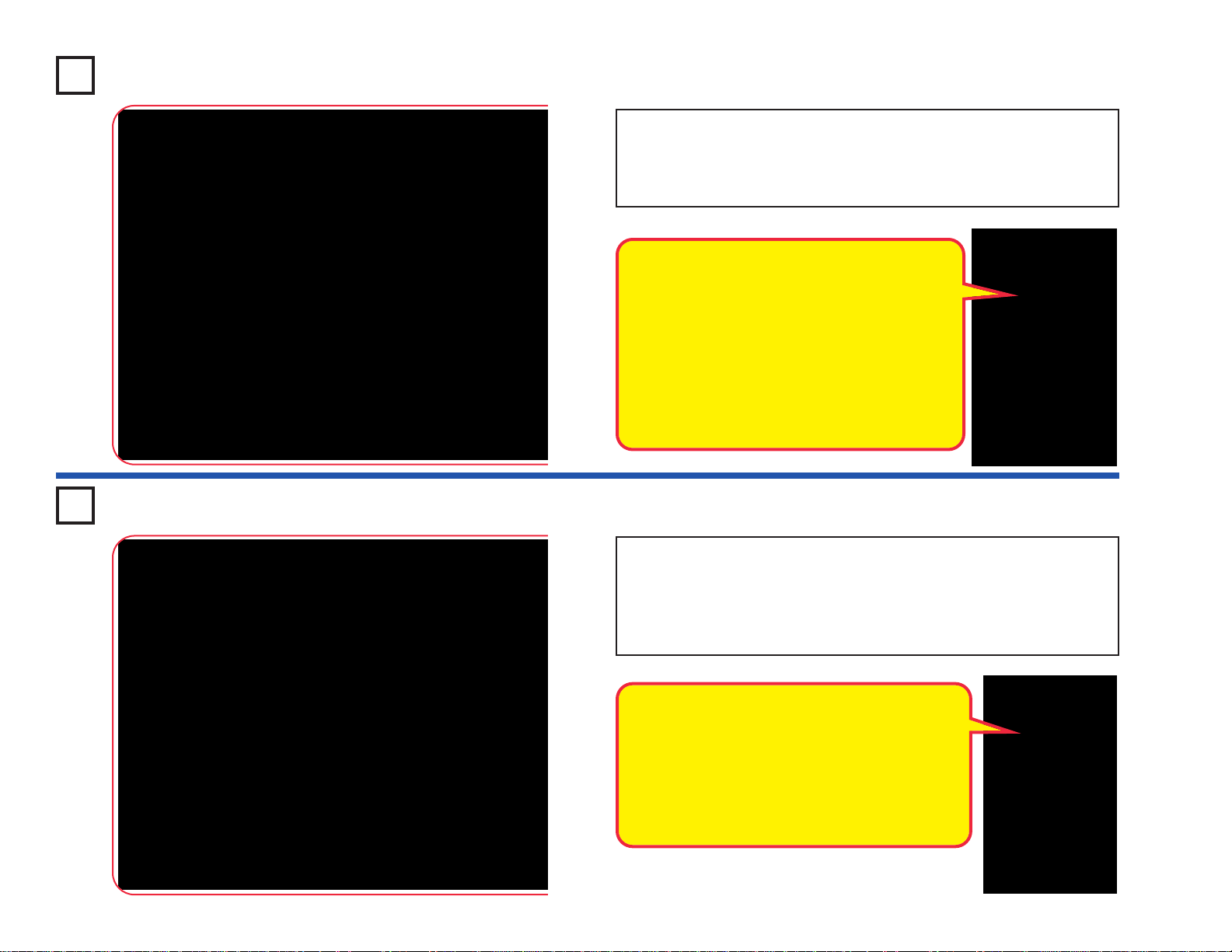
-41-
Project 59 LEDs Together
Project 60 LEDs Together (II)
Turn on the slide switch (S1), and compare the brightness of the three
LEDs.
Next, remov e any of the LEDs and see how the brightness of the others
changes.
Modify the preceding circuit by moving the slide switch (S1) to the
location shown here. Compare the brightness of the LEDs. Some LEDs
may not turn on.
Next, remov e any of the LEDs and see how the brightness of the others
changes.
This circuit reduces the voltage to the circuit,
because only one set of batteries is connected.
The limited battery voltage is split between the R1
resistor and the LEDs. The remaining voltage
across the LEDs is enough to activate the red
LEDs, but may not be enough to activ ate the other
colors. With the reduced voltage, the red LED will
dominate even more than in the preceding circuit.
The voltage needed for an LED to turn on
depends on the light color. Red light needs the
least, green needs more, but blue and white
need the most. The color LED (D8) contains red,
green, and blue LEDs.
The R1 resistor reduces the voltage available to
the LEDs. The LED brightness varies because
some of the LEDs need more voltage than is
available. The red LED (D1) will dominate the
other colors because it turns on more easily.
Page 43

-42-
Project 61 Brightness Control
Project 62 Resistors Project 63
Resistors & LEDs
Use the circuits from projects 61 and 62, but
replace the white LED (D6) with the red LED
(D1) or color LED (D8). Vary the adjustable
resistor lever and change the yellow resistors to
see how the light varies with each LED.
Use the circuit built in project 61, but replace the 3-snap with one
of the yellow resistors in this set (R1, R3, or R5). Obser ve how
each changes the LED brightness at different settings for the
adjustable resistor.
Build the circuit and turn on the slide switch (S1). Mo v e the lev er on the
adjustable resistor (R V) to vary the brightness of the light from the white
LED (D6). If desired, y ou ma y place any of the LED attachments (tower ,
egg, or fiber optic tree) on the LED.
Resistors are used to control or limit the flow of electricity in a circuit.
Higher resistor values reduce the flow of electricity in a circuit.
In this circuit, the adjustable resistor is used to adjust the LED brightness,
to limit the current so the batteries last longer, and to protect the LED
from being damaged by the batteries.
What is Resistance? Take your hands and rub them together very fast.
Your hands should feel warm. The friction between your hands converts
your effort into heat. Resistance is the electrical friction between an
electric current and the material it is flowing through.
The adjustable resistor can be set for as low as 200Ω, or as high as
50,000Ω (50kΩ).
The R1 resistor (100Ω) will have
little effect, since it will be
dominated by the adjustable
resistor. Resistor R5 (100kΩ) is a
high resistance, which greatly
restricts the flow of electricity, so
the LED will be very dim or off.
Resistor R3 (5.1kΩ) will be in
between those.
Page 44
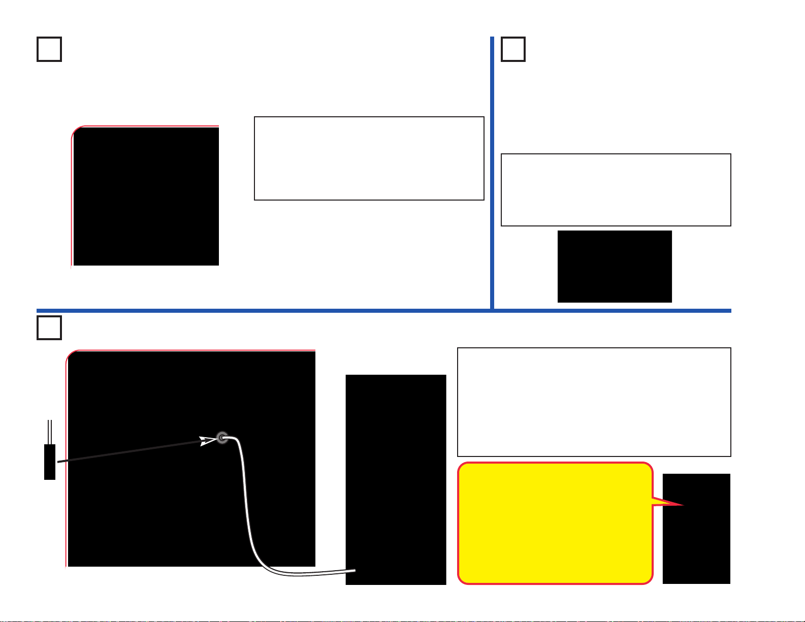
-43-
Project 64
Low Power Brightness Control
Project 65
Low Power
Resistors & LEDs
Use the circuit from project 64, but replace the
color LED (D8) with the red LED (D1) or white
LED (D6). Vary the adjustable resistor lever to
see how the light varies with each LED . The white
LED may not be on at all.
Project 66 Persistence of Vision
Build the circuit as shown. Place the blac k fiber optic cab le
holder on the white LED (D6) and insert the fiber cable into
the black holder as f ar as it will go . Turn on the slide switch
(S1). Take the circuit into a dark room and wave the cable
around while watching the loose end. Try it with the lever
on the adjustable resistor (RV) at different settings. The
light coming out the loose end of the fiber optic cable will
separate into short segments or dashes of light.
Build the circuit and turn on the slide switch (S1).
Move the le ver on the adjustable resistor (RV) to
vary the brightness of the light from the color
LED (D8). For best effects, do this in a dimly lit
room. At some RV settings the LED will be very
dim, and some of its colors may be totally off.
Black
“Persistence of Vision” works because the light
is changing faster than your eyes can adjust.
Your eyes continue seeing what they ha ve just
seen.
In a movie theater, film frames are flashed on
the screen at a fast rate (usually 24 per
second). A timing mechanism makes a light
bulb flash just as the center of the frame is
passing in front of it. Your eyes see this fast
series of flashes as a continuous movie.
Page 45
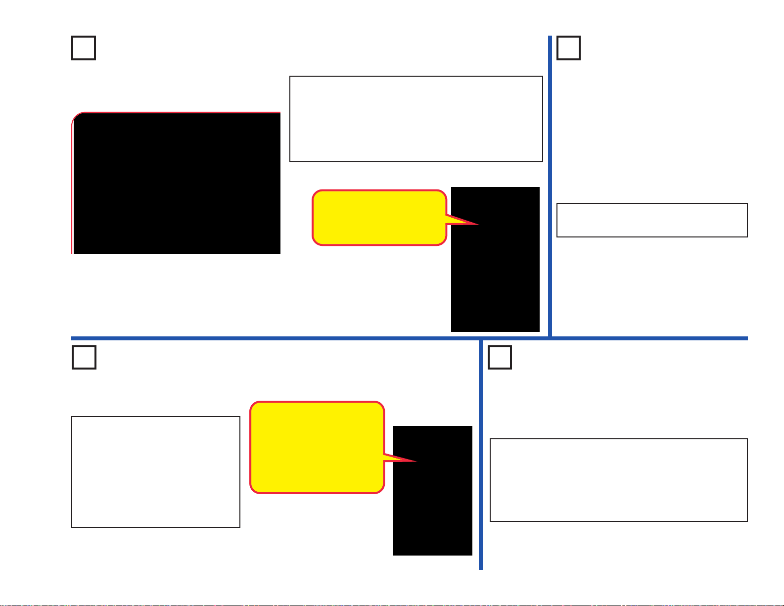
-44-
Project 69 Scattering Light
Project 67 Prismatic Film Project 68
Look at the
Lights
View different light sources in and around
your home through the prismatic film.
This is the same circuit as project 1, but you will view it
differently. Tur n on the switch (S1), and view the LED
through the prismatic film (the clear slide). Prismatic film
makes interesting light effects.
Replace the color LED (D8) with the white LED (D6)
and red LED (D1); view them through the prismatic film.
Project 70
Color Fiber Light
Prismatic film separates light
into different colors. White
light is a combination of all
colors.
Use the project 67 circuit, but view
the color LED through various semitransparent liquids, glassware, and
plastics. Juices, jello, and cloudy
glass or plastic work well.
Replace the color LED with the
white LED (D6). The white LED is
brighter, but does not change color.
Semi-transparent materials
scatter the light without
completely blocking it, so a
wide area of the liquid or
material is lit up by the light.
This happens in the egg and
tower LED attachments.
Use the circuit from project 67, but place the clear cable
holder on the color LED (D8), then place the fiber optic
cable into the holder as far as it will go. Turn on the
switch, then take the circuit into a dimly lit room and see
the light coming out the open end of the cable. The light
travels through the cable even as you bend it around.
Page 46
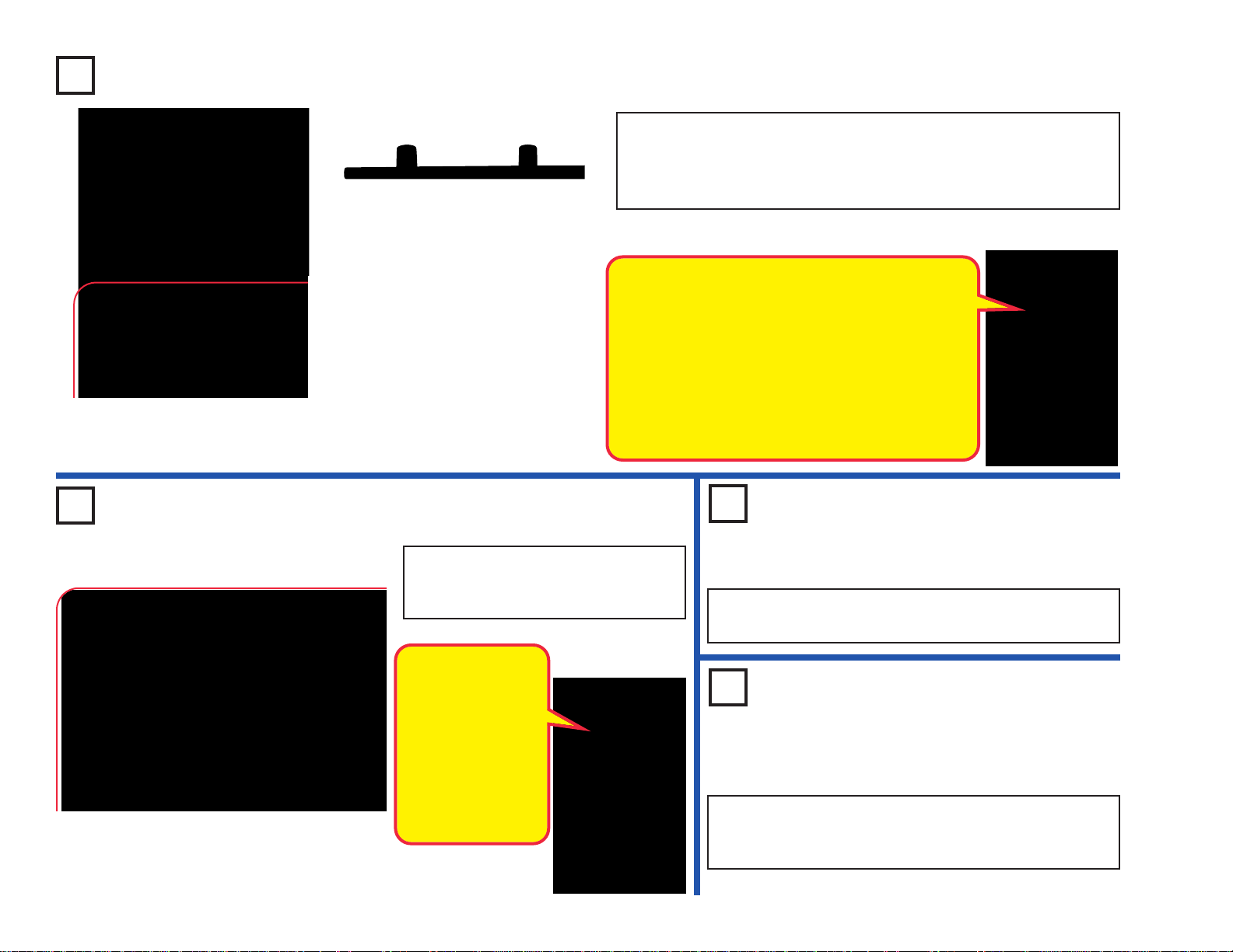
-45-
Project 71 One Way Plastic
Project 72 White Blinker
Build the circuit shown, but build it without using the base grid. Turn on
the switch (S1) and view the color LED (D8) light through the base grid.
Then turn the base grid on its side and try to see through it; you can’t.
Try viewing other lights through other clear materials.
Side view of base grid
Build the circuit as shown and turn on
the switch (S1). Both LEDs are
blinking.
The color LED (D8)
has a microcircuit
that changes the
light colors. As it
does this, it changes
the current through
the circuit - which
also affects the
brightness of the
white LED (D6).
Use the preceding circuit, but replace the white LED (D6)
with the red LED (D1).
Project 74
Red & White
Project 73
Red Blinker
Use the preceding circuit, but replace the color LED (D8)
with the white LED (D6). Both LEDs light, but neither in
blinking.
The main surface of the base grid is flat and smooth,
giving a nice transition for light ra ys to pass through.
If you look closely at the side edges (using a
magnifying glass helps), you will see they are slightly
curved. These curves, and the angle of the light
hitting them, cause more light to be scattered or
reflected than light hitting the main surface. Some
materials can also pass light better in some
directions than in other directions, due to their
physical structure.
Page 47
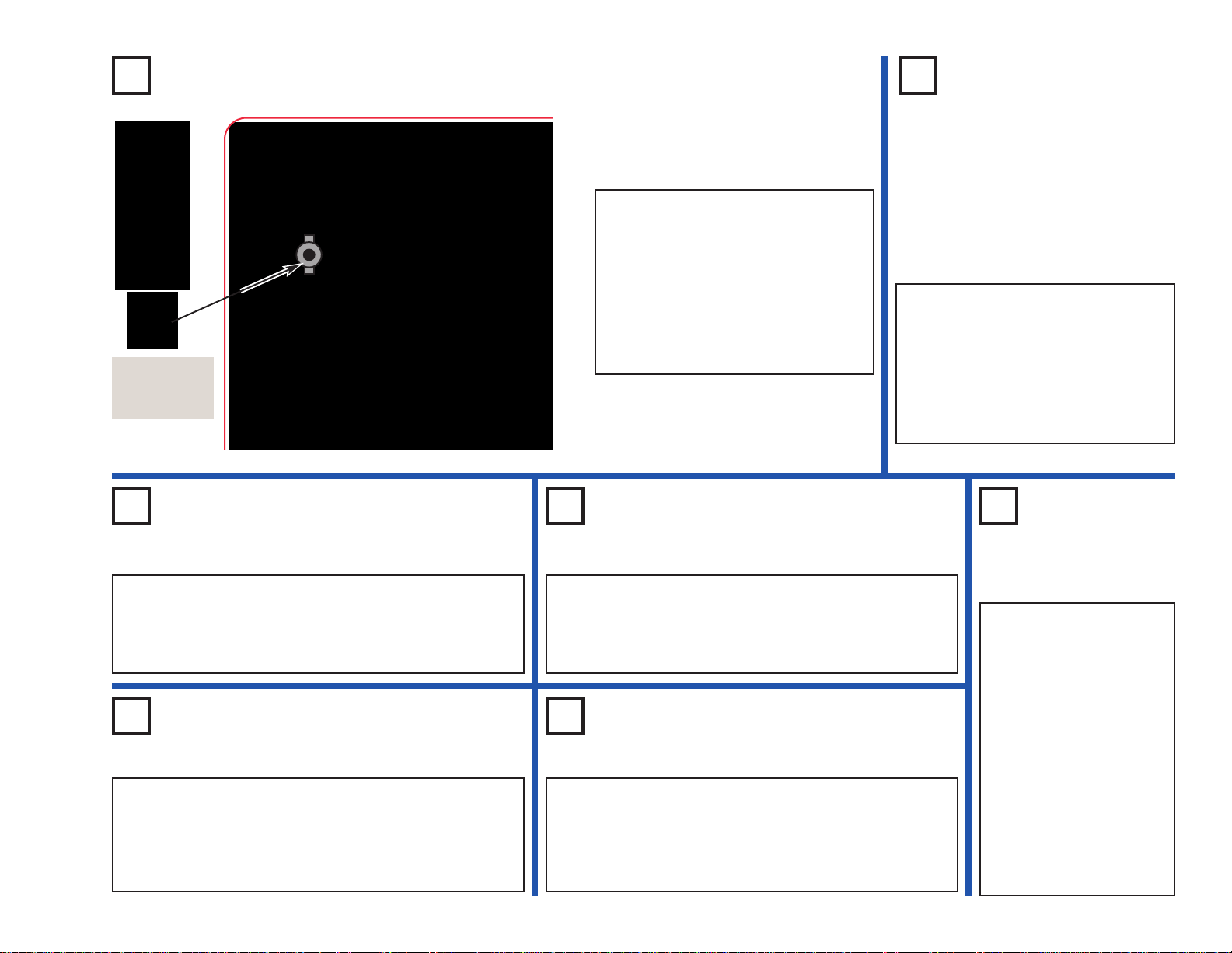
-46-
Project 75 Color Selector - Red
Project 76
Color
Selector -
Green
Use the preceding circuit, but
remove the 2-snap between points
A & B, and add one between
points C & D. Now the color is
green. Look at it using the fiber
optic tree, and then the prismatic
film.
Build the circuit as shown. Place
the fiber optic tree and mounting
base on the color organ (U22).
Turn on the switch (S1). The color
organ makes a red light. Remove
the fiber optic tree and mounting
base, and look at the light through
the prismatic film.
Project 77
Color Selector - Blue
Use the preceding circuit, but remove the 2-snap
between points C & D, and add one between points
E & F. Now the color is b lue. Look at it using the fiber
optic tree, and then the prismatic film.
Project 78
Color Selector - Cyan
Use the preceding circuit, but add a 2-snap between
points C & D. Now the color is cyan, which is a
combination of green and blue. Look at it using the
fiber optic tree, and then the prismatic film.
Project 80
Color Selector - Purple
Use the preceding circuit, but remove the 2-snap
between points C & D, and add one between points
E & F. Now the color is purple, which is a
combination of red and blue. Look at it using the fiber
optic tree, and then the prismatic film.
Project 81
Color Selector -
White
Use the preceding
circuit, but add a 2snap between points C
& D. Now the color is
white, which is a
combination of red,
green, and blue. Look
at it using the fiber
optic tree, and then the
prismatic film.
Black is made by
turning off all the
colors.
Prismatic
film
Project 79
Color Selector - Yellow
Use the preceding circuit, but remove the 2-snap
between points E & F, and add one between points
A & B. Now the color is yellow, which is a
combination of red and green. Look at it using the
fiber optic tree, and then the prismatic film.
Page 48

-47-
Project 82
LED Color Spectrum
Project 83
LED Color
Spectrum (II)
Use the preceding circuit, but remove the 2-snap
across points W-W and place 2-snaps across R-R
and G-G. Use the prismatic film to look at the color
spectrum. View from different directions and
different angles.
Next, move the 2-snaps to R-R and B-B, and look
at the spectrum. Then mo ve the 2-snaps to G-G and
B-B and look at the spectrum. View from different
directions and different angles.
For each combination, the color spectrum should
be mostly light of the 2 individual colors you are
combining.
Build the circuit as shown, and turn
on the switch (S1). The white LED
(D6) will be on. Look at the white
LED through the prismatic film to see
the color spectrum of white light,
which is all the colors of a rainbow.
For best effects, do this in a dimly lit
room.
Now remove the 2-snap across
points W-W, and place it across
points C-C (the color LED), then
points R-R, G-G, and B-B (for the
color organ). Using the prismatic film,
look at the color spectrum produced
by the color LED, and the different
colors from the color organ.
Compare them to the white LED
spectrum.
Project 84
LED Color Spectrum (III)
Use the preceding circuit, but place 2-snaps across points R-R, G-G,
and B-B. Use the prismatic film to look at the color spectrum. View from
different directions and different angles.
With the above connections, the color organ (U22) produces white
light. The actual color spectrum you see will vary with your viewing
angle, because the light is produced using separate red, green, and
blue LEDs next to each other.
Now remove the 2-snaps from R-R, G-G, and B-B, and place one
across W-W, so the circuit is like the project 82 drawing. Use the
prismatic film to view the color spectrum from the white LED (D6)
again, and compare it to the white light spectrum from U22. The D6
spectrum does not vary as much with the viewing angle because the
light is produced by a single LED, and it is brighter.
Project 85
LED Color Spectrum (IV)
Use the circuit combinations from projects
82-84, but look at the different lights through
the red, green, or blue filters instead of the
prismatic film. Each filter only allows you to
see light of that color, and blocks the other
colors. If you put all three filters together
then all light is blocked.
Actually, the red filter will pass a little of the
green light, the blue filter will pass a little of
the green light, and the green filter will pass
a little of the green and blue light. This is
because green light is between red and blue
light in the color spectrum, and the filters are
not perfect. See page 13 for more
information about the color spectrum.
Project 86
LED Color
Spectrum (V)
Repeat project 82, but place
the black fiber optic cable
holder with the fiber optic
cable on the LED you want
to view. Look at the light
coming out the other end of
the cable using the prismatic
film, and view in a dimly lit
room. The light is not as
bright but the beam is
narrower, so the color
spectrum may be clearer.
Page 49
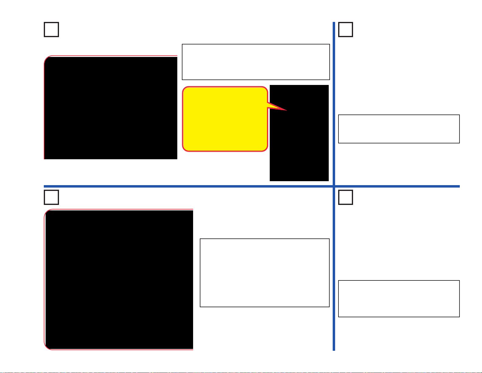
-48-
Project 87 Blinking Beeping
Build the circuit as shown and turn on the switch
(S1). The color LED (D8) will be blinking and you
hear beeping from the speaker. The sound will not
be very loud.
Project 89 Blinking Control
Build the circuit as shown and turn on the
switch (S1). The color LED (D8) and white
LED (D6) will both be blinking. The color LED
will be brighter than in the preceding circuit.
The white LED is controlled by the color LED
using the transistor (Q2). If you remove the
color LED from the circuit then the white LED
will not blink.
Project 90
Blinking Control
Beeping
Use the preceding circuit, but replace the
white LED (D6) with the speaker (SP). Now
the blinking LED controls a beeping sound,
but the sound will not be very loud.
Project 88
Blinking
Blinking
Use the preceding circuit, but replace the
speaker with the red LED (D1). Now the
red LED will also be blinking.
The color LED (D8) has a
microcircuit that changes the
light colors. As it does this, it
changes the current through
the circuit. The transistor (Q2)
amplifies the changing
current and uses it to control
the speaker (SP).
Page 50

-49-
Project 92 Funny Speed Motor
Build the circuit as shown and turn on the switch
(S1). The color LED (D8) is blinking and the motor
(M1) spins at different speeds. T ry this circuit with the
glow fan on the motor, and without the fan.
The motor is controlled by the color LED using the
transistor (Q2). If you remov e the color LED from the
circuit then the motor will not spin.
Project 93
Funny Speed
Motor with
Light
Use the preceding circuit, but
add the red LED (D1) across
points A & B (“+” to A). This
adds another blinking light.
Project 91 Triple Blinker
Build the circuit as shown and turn on the switch (S1). Three LEDs (D1,
D6, and D8) will be blinking.
The red and white LEDs are controlled by the color LED using the
transistor (Q2). If you remove the color LED from the circuit then the
other LEDs will not blink.
!
WARNING: Moving parts. Do not
touch the fan or motor during
operation.
In this circuit the color LED is
powered by one set of batteries, and
the motor is powered by diff erent set.
This was done because the motor
produces electrical pulses as it spins,
and these pulses can confuse the
color LED.
Page 51
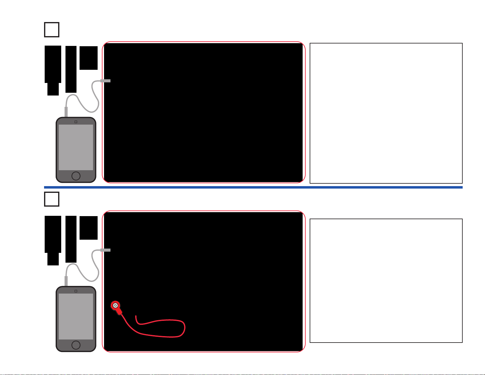
-50-
Project 94 Light Dance Audio Override
Project 95 Light Dance Light Override
Build the circuit, which is similar to project 34 (Dance
to the Music). Connect a music device (not included)
to the color organ (U22) as shown, and start music on
it. Place one of the LED attachments o ver the light on
the color organ. Set the le v er on the adjustable resistor
(RV), and the v olume control on your music de vice, f or
best sound quality and light effects. The color organ
light will “dance” in synch with the music.
For the next part, you need the color organ light to be
changing slowly. Set your music device to play a song
with a slow beat, and set the volume control on it so
the sound is not very loud.
Now blow on the microphone (X1) or talk loud directly
into it. The dancing light pattern should be interrupted
by your blowing/talking. If you don’t notice any
difference then lower the v olume control on your m usic
device. Songs with a slower beat work best for this.
MP3
player
Build the circuit, which is similar to project 34
(Dance to the Music). Connect a music device
(not included) to the color organ (U22) as shown,
and start music on it. Place one of the LED
attachments over the light on the color organ.
Cover the phototransistor (Q4) with your hand
and set the lever on the adjustable resistor (RV),
and the volume control on your music device, for
best sound quality and light effects. The color
organ light will “dance” in synch with the music.
Uncover the phototransistor and shine a bright
light on it. The color organ light will stop changing
until you re-cover the phototransistor. The music
will not be affected.
MP3
player
LED Attachments
LED Attachments
Page 52
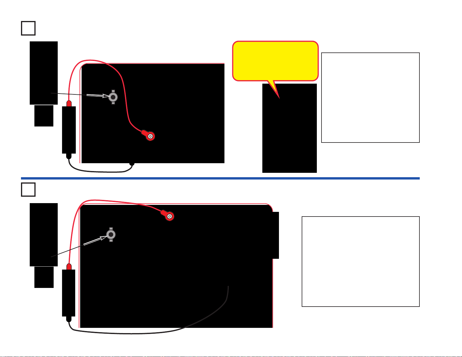
-51-
Project 96 Counting Light
Project 97 Adjustable Counting Light
Build the circuit as shown and turn
on the switch (S1). Place one of the
LED attachments over the LED on
the color organ (U22). Connect the
color LED (D8) using the red &
black jumper wires and hold it just
above the phototransistor (Q4), so
that it shines directly into the
phototransistor. For best effects, do
this in a dimly lit room. Ever y few
seconds, the color organ light will
change colors.
The color organ is counting
how many times light turns the
phototransistor on or off. At
some count levels, the color
organ changes colors.
Build the circuit as shown and turn on the
switch (S1). Place one of the LED
attachments over the LED on the color
organ (U22). Connect the white LED (D6)
using the red & black jumper wires and
hold it just above the phototransistor (Q4),
so that it shines directly into the
phototransistor. For best effects, do this in
a dimly lit room. The color organ light will
change colors, the lever on the adjustable
resistor (RV) controls how fast the colors
change.
Page 53
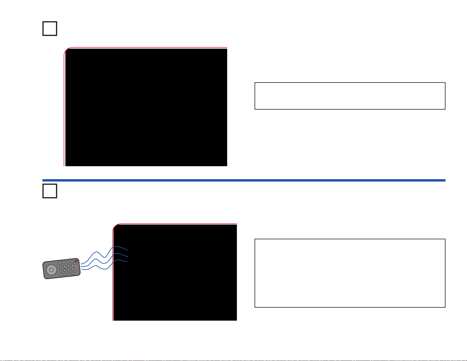
-52-
Project 98 Bright Off Light
Build the circuit as shown and turn on the switch (S1). Place the circuit in
a dark room or cover the phototransistor (Q4); the color LED (D8) should
be on. Shine light on the phototransistor and the color LED turns off.
Project 99 R/C Blink & Beep
Remote
You need an infrared remote control for this project, such as any
TV/stereo/DVD remote control in your home.
Build the circuit and turn on the switch (S1). Point your remote control
toward the infrared module (U24) and press any button to activate the
red LED (D1) and speaker (SP).
Sometimes this circuit may activate without a remote control, due to
infrared in sunlight or some room lights. If this happens, tr y moving to
a dark room.
Page 54
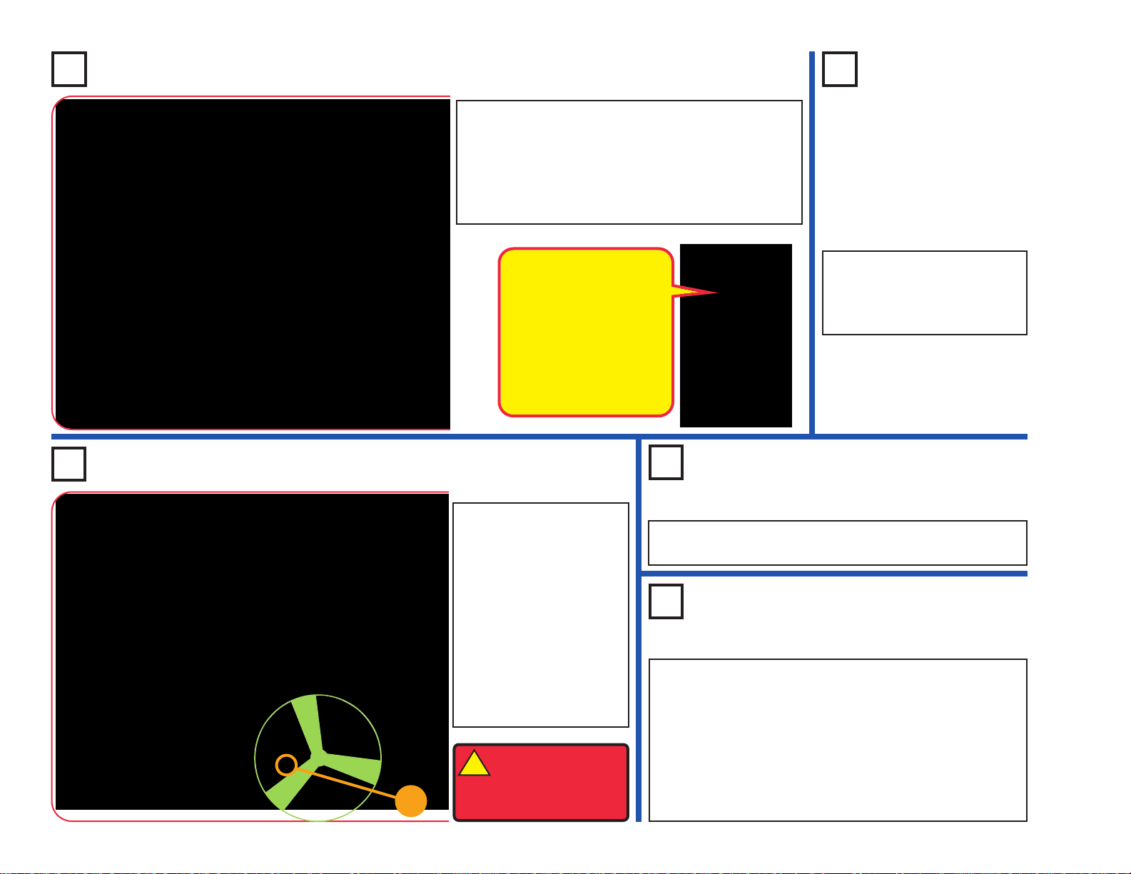
-53-
Project 102 White Blinker
Build the circuit as shown,
and note that several
parts are stacked over
others. Turn on the slide
switch (S1); nothing
happens.
Now push the press
switch (S2); the motor
(M1) turns on and stays
on. The motor will stay on
until you turn off the slide
switch.
Use the preceding circuit, but replace the motor with the
red LED (D1).
Project 104
Stuck On Motor & Lights
Project 103
Low Voltage Stuck On Lights
Use the project 102 circuit but place the red LED (D1) next to
the motor at base grid locations G5-G7 (“+” to G5). Connect the
red LED to the adjacent points on the motor using the red &
black jumper wires, making sure the jumper wires do not touch
the motor or fan.
Turn on the slide switch (S1), then push the press switch (S2).
The motor spins and the red LED is dim. Tur n off the circuit,
remove the fan from the motor, and turn the circuit back on. Now
the red LED is bright because it takes less electricity to spin the
motor without the fan, leaving more electricity for the red LED.
Stuck On Light
Build the circuit as shown, and note that several
parts are stacked over others. Turn on the slide
switch (S1); nothing happens.
Now push the press switch (S2); the white LED (D6)
turns on and stays on. The white LED will stay on
until you turn off the slide switch.
Project 101
Stuck On
Lights
Use the preceding circuit, but
replace the 100Ω resistor
(R1) with the color LED (D8)
or the red LED (D1).
!
WARNING: Moving
parts. Do not touch
the fan or motor
during operation.
Project 100
The two transistors act as
an electronic device
called an SCR (Silicon
Controlled Rectifier). An
SCR is a three-pin device
that once its control pin is
triggered, remains on
until the current flow
through it stops.
+
Page 55

-54-
Project 105 Funky Light & Sound
Build the circuit as shown
and turn on the switch
(S1). The color LED (D8)
is used to control the
strobe IC (U23), producing
unusual effects.
Use the preceding circuit, but
replace the
color LED (D8) with the 100kΩ resistor (R5)
or the 5.1kΩ resistor (R3).
Project 107
Light & Motion
Project 106
Light & Sound
Adjustable Light & Sound
Modify the preceding circuit to match
the one shown here. Use the lever on
the adjustable resistor (RV) to control
the light & sound. At some settings the
white LED (D6) will not light, or will
appear to be on continuously.
Project 109
Adjustable
Light &
Motion
Use the preceding circuit, but
replace the speaker with the
motor (M1) and glow fan
(motor “+” toward S1).
Project 108
Repeat projects 105 & 106 but replace the
speaker with the motor (M1) and glow fan
(motor “+” toward S1).
!
WARNING: Moving parts. Do not
touch the fan or motor during
operation.
!
WARNING: Moving
parts. Do not touch the
fan or motor during
operation.
Page 56
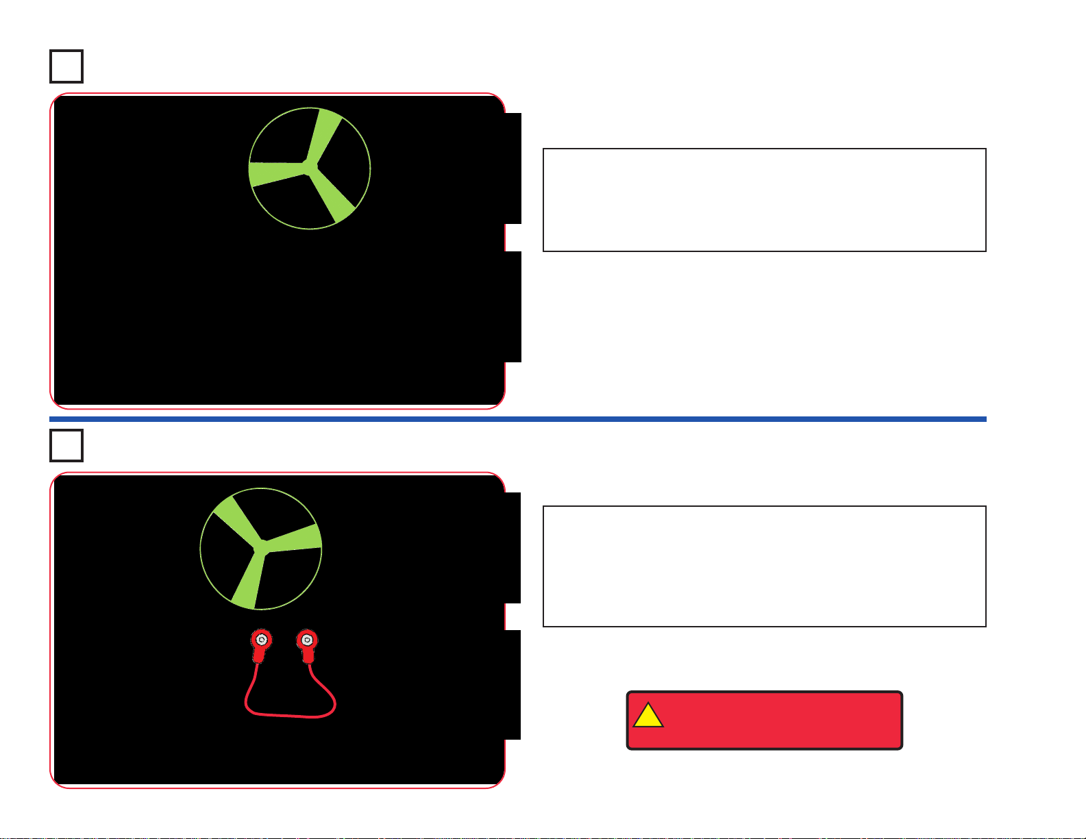
-55-
Project 110 Blinking Step Motor
Project 111 Blink Step Beep
Build the circuit as shown and turn on the switch (S1). The color LED
(D8) is used to control the strobe IC (U23), which turns on the motor
(M1) in short bursts.
To have 3 LEDs, place the red LED (D1) directly over the white LED
(D6).
Build the circuit as shown and turn on the switch (S1). The color LED
(D8) is used to control the strobe IC (U23), which turns on the motor
(M1), white LED (D6), and speaker (SP) in short bursts. The circuit also
works without the fan on the motor.
If you replace the motor with the black jumper wire, the white LED will
be a little brighter.
!
WARNING: Moving parts. Do not
touch the fan or motor during
operation.
Page 57
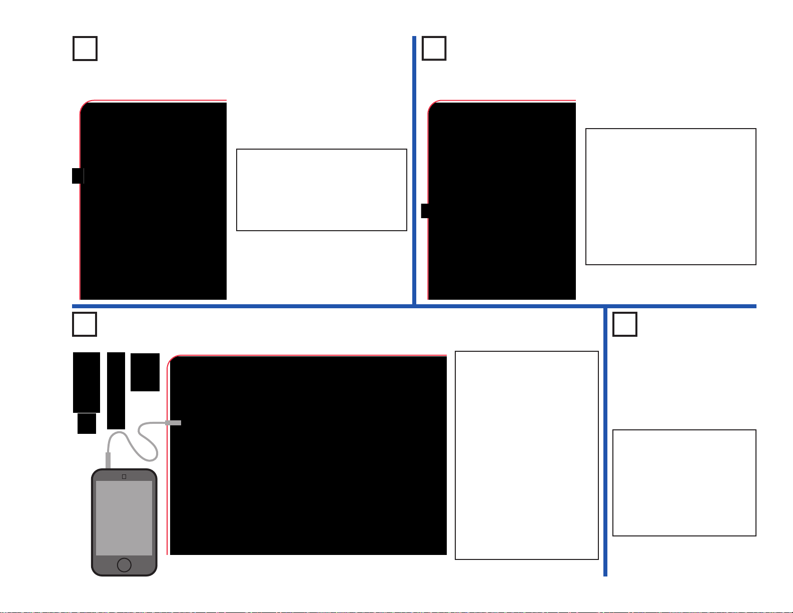
-56-
Project 113
Night Blinker
Project 112
Day Blinker
Night Light Show
Project 115
Daylight
Light Show
Use the preceding circuit, but
swap the locations of the
phototransistor (Q4) and the
100kΩ resistor (R5), put the
“+” side of Q4 towards the
NPN transistor (Q2). Now
covering the phototransistor
turns off the light show.
Project 114
MP3
player
Build the circuit as shown and turn
on the switch (S1). The color LED
(D8) is on when there is light on the
phototransistor (Q4). Shine light on
or cover the phototransistor to turn
the color LED on or off.
Build the circuit as shown and turn
on the switch (S1). The color LED
(D8) is off when there is light on the
phototransistor (Q4). Cov er or shine
light on the phototransistor to turn
the color LED on or off.
If the color LED comes on too
easily, reduce the sensitivity by
replacing the 5.1kΩ resistor (R3)
with the 100kΩ resistor (R5).
Build the circuit as shown.
Connect a music device (not
included) to the color organ
(U22) as shown, and start
music on it. Place one of the
LED attachments over the
light on the color organ. Tur n
on the switch (S1), then cov er
the phototransistor (Q4) to
see a light show. Adjust the
volume on your music device
for best light effects.
Replace the 100kΩ resistor
(R5) with the 5.1kΩ resistor
(R3) to make the light
brighter.
LED Attachments
Page 58

-57-
Project 116 Buzzer
Project 118
Photo Light & Motion
Project 119
Slow Light &
Motion
Use the circuits from projects 116-117,
but replace the 0.1µF capacitor (C2)
with the 100µF capacitor (C4), “+” to
the right. Turn the switch on and
patiently wait. The speaker will beep
and the color LED (D8) will flash every
5-20 seconds, depending on the
resistors.
Use the circuits from projects 116-117, but add the phototransistor (Q4)
across base grid locations B2-B4 (between RV and R1, “+” on the left), on
level 3. Var y the amount of light on the phototransistor to change the
sound, while also varying RV.
Light Up the FanProject 120
This circuit is an
oscillator, which uses
feedback to control
the pitch of the
sound.
Build the circuit as shown, place the glow fan on the motor
(M1), and turn on the slide switch (S1). Place the circuit in
a dark room and push the press switch (S2) to spin the fan.
The color LED (D8) lights up the spinning fan.
!
WARNING: Moving parts. Do not
touch the fan or motor during
operation.
The circuit with the color LED is not
electrically connected to the circuit with the
motor. This was done because the motor
produces electrical pulses as it spins, and
these pulses can confuse the color LED.
Build the circuit as shown and
turn on the switch (S1). Mo ve
the lever on the adjustable
resistor (RV) to v ary the pitch
of the buzzing sound.
Project 117
Higher Pitch Buzzer
Use the preceding circuit, but place the 5.1kΩ resistor directly over the
100kΩ resistor using a 1-snap. The pitch of the tone is higher now, but the
circuit may not make noise on all settings for the adjustable resistor.
Page 59

-58-
Project 121
High Power Buzzer
Project 123
Photo Buzzer
Use the circuits from projects 121-122, but add the
phototransistor (Q4) across base grid locations B2B4 (between RV and R1, “+” on the left), on level 3.
Shine a bright light on the phototransistor to change
the sound, while also moving the lever on RV.
You can also place the phototransistor directly
over the 100kΩ resistor, as done for the 5.1kΩ
resistor in project 122. For this arrangement,
“+” on Q4 should be on the right.
Project 124
Step Beeper
Use the circuits from projects 121-123, but replace the 0.1µF capacitor
(C2) with the 100µF capacitor (C4), “+” to the right. The motor will move
in small bursts, with long intervals or almost continuously, depending on
the resistors and phototransistor.
Next, replace the color LED (D8) with the white LED (D6). See how the
circuit works now.
Project 125
Wacky Buzzer
Repeat projects 121-123, but add the 100µF capacitor (C4) across the
points marked A & B in the drawing (“+” to A). The motor may not spin but
the sound is different. The sound may not be very loud.
Project 122
Buzz Fan
Use the preceding circuit, but place the 5.1kΩ
resistor (R3) directly over the 100kΩ resistor
(R5) using a 1-snap. The pitch of the tone is
higher now, and the fan spins. The circuit may
not make noise on all settings for the
adjustable resistor. The motor may not spin.
Build the circuit as
shown and turn on the
switch (S1). Move the
lever on the adjustable
resistor (RV) to v ary the
pitch of the buzzing
sound. The motor (M1)
may not spin.
!
WARNING: Moving parts. Do not
touch the fan or motor during
operation.
Page 60
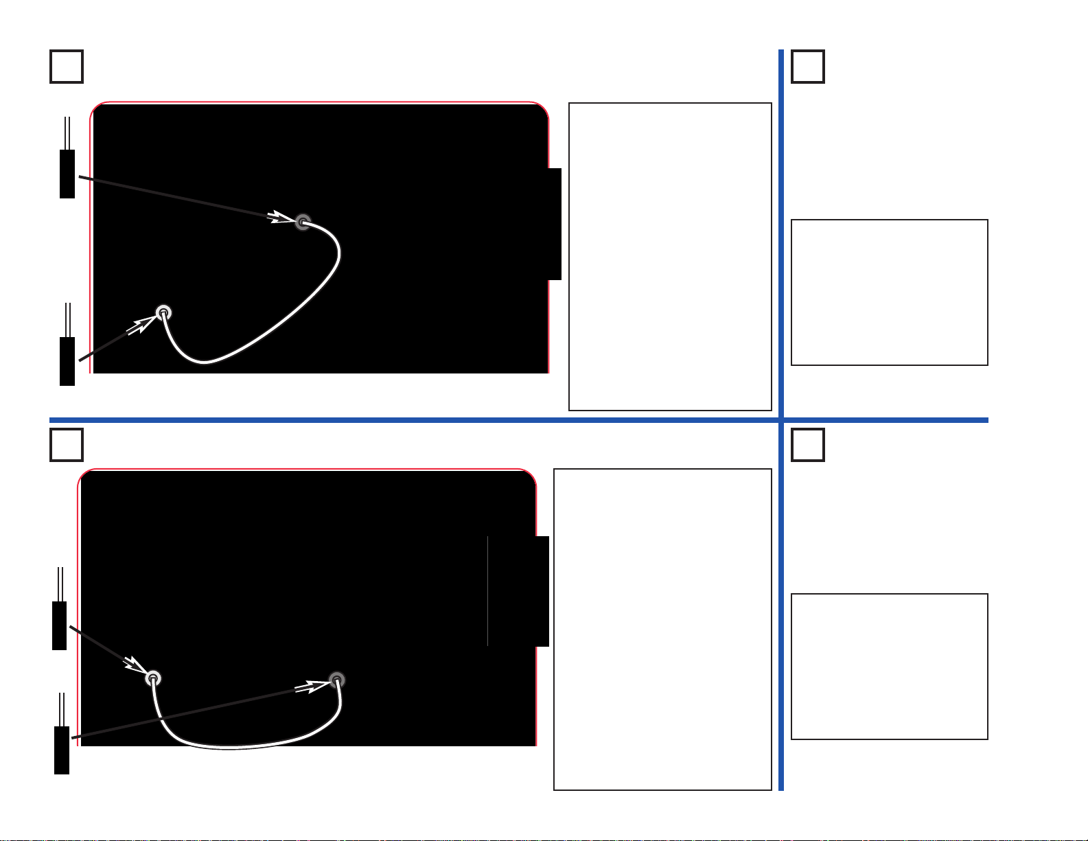
-59-
Project 126 Fiber Fun
Project 127
Fiber Fun
Backwards
Use the preceding circuit but
swap the locations of the
phototransistor (Q4) and the
100kΩ resistor (R5), keep the
“+” side of Q4 in the same
direction. Now the red LED
will be on whenever the color
LED is off.
Build the circuit as shown.
Place the clear cable holder on
the color LED (D8) and the
black cable holder on the
phototransistor (Q4), then
place the fiber optic cable into
the holders as far as it will go.
Turn on the slide switch (S1).
Light is transmitted from the
color LED, through the fiber
optic cable, to control the NPN
transistor (Q2) and red LED
(D1).
You can replace the red LED
with the white LED (D6), but
the white LED may be dim or
not light.
Project 128 More Fiber Fun
Project 129
Other
Fiber Fun
Use the preceding circuit but
swap the locations of the
phototransistor (Q4) and the
100kΩ resistor (R5), keep the
“+” side of Q4 in the same
direction. Now the red LED
will be on whenever the color
LED is on.
Build the circuit as shown. Place the
clear cable holder on the color LED
(D8) and the black cable holder on the
phototransistor (Q4), then place the
fiber optic cable into the holders as far
as it will go. For best performance the
fiber optic cable should stand straight
up in the holders, without bending them.
Turn on the slide switch (S1). Light is
transmitted from the color LED,
through the fiber optic cable, to control
the PNP transistor (Q1) and red LED
(D1). The speaker is used to help limit
the current through the color LED, and
will not make noise.
For more fun, swap the locations of
the color LED (D8) and red LED (D1).
You may also replace either LED with
the white LED (D6), but the white LED
may be dim or not light.
Black
Clear
Clear
Black
Page 61
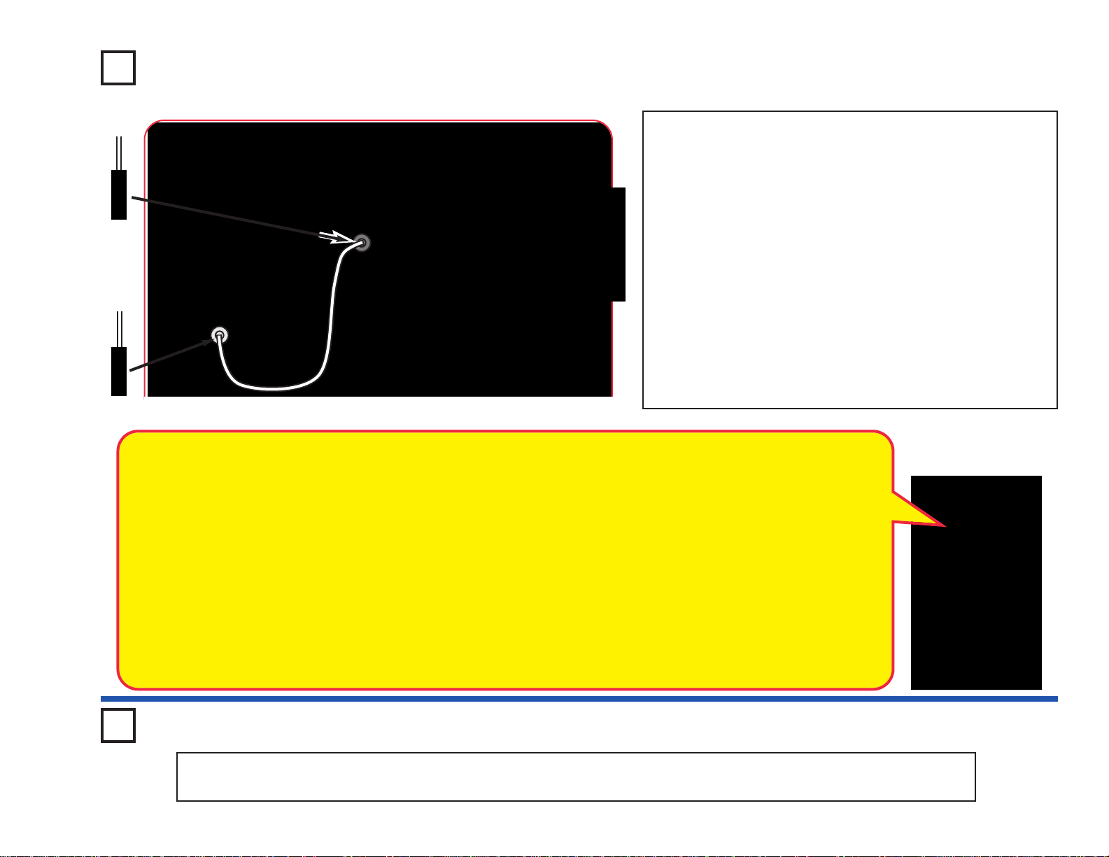
-60-
Build the circuit as shown. Place the clear cable holder on the red
LED (D1) and the black cable holder on the phototransistor (Q4),
then place the fiber optic cable into the holders as far as it will go .
For best performance the fiber optic cable should stand straight
up in the holders, without bending them.Turn on the slide switch
(S1), then push the press switch (S2) sev eral times to send secret
messages between the circuits using Morse Code. If your fiber
optic cable was a lot longer, you could use this circuit to send
messages to your friends in different cities. The speaker is used
to help limit the current through the red LED, and will not make
noise.
If desired, you can swap the locations of the red and white LEDs
(D1 & D6).
Note: If the white LED (D6) does not light or is dim, replace it
with the color LED (D8). The white LED can be brighter and won’t
change colors, but requires higher voltage to activate.
Project 130 Morse Code
Morse Code: The forerunner of today’s telephone system
was the telegraph, which was widely used in the latter half
of the 19th century . It only had two states - on or off (that is,
transmitting or not transmitting), and could not send the
range of frequencies contained in human voices or music.
A code was developed to send information over long
distances using this system and a sequence of dots and
dashes (short or long transmit bursts). It was named Morse
Code after its inventor. It was also used extensively in the
early days of radio communications, though it isn’t in wide
use today. It is sometimes referred to in Hollywood movies,
especially Westerns. Modern fiber optics communications
systems send data across the country using similar coding
systems, but at much higher speeds.
MORSE CODE
A . _
B _ . . .
C _ . _ .
D _ . .
E .
F . . _ .
G _ _ .
H . . . .
I . .
J . _ _ _
K _ . _
L . _ . .
M _ _
N _ .
O _ _ _
P . _ _ .
Q _ _ . _
R . _ .
S . . .
T _
U . . _
V . . . _
W . _ _
X _ . . _
Y _ . _ _
Z _ _ . .
Period
. _ . _ . _
Comma
_ _ . . _ _
Question . . _ _ . .
1 . _ _ _ _
2 . . _ _ _
3 . . . _ _
4 . . . . _
5 . . . . .
6 _ . . . .
7 _ _ . . .
8 _ _ _ . .
9 _ _ _ _ .
0 _ _ _ _ _
Project 131 Fiber Shut-Off
Use the preceding circuit but swap the locations of the phototr ansistor (Q4) and the 100kΩ resistor (R5), k eep the “+” side of Q4
in the same direction. Now pushing the press switch will turn off the LED in the right half of the circuit.
Black
Clear
Page 62

-61-
Project 132 Blow On Fiber
Project 133 Fiber Music
Build the circuit as shown. Place the clear
cable holder on the color organ (U22) and
the black cable holder on the
phototransistor (Q4), then place the fiber
optic cable into the holders as far as it will
go. For best performance the fiber optic
cable should stand straight up in the
holders, without bending them.The clear
holder will be a loose fit.
Connect a music device (not included) to
the color organ as shown, and start the
music on it. The music pla ys on the speaker
(SP) while the LED on the color organ
controls the red LED (D1) through the fiber
optic cable. Set the volume control on your
music device for best light & sound effects.
MP3
player
Build the circuit as shown. Place the clear
cable holder on the color LED (D8) and the
black cable holder on the phototransistor
(Q4), then place the fiber optic cable into
the holders as far as it will go. For best
performance the fiber optic cable should
stand straight up in the holders, without
bending them.
Turn on the slide switch (S1), and blow on
the microphone or talk loudly into it. The
signal from the microphone will be sent
through the fiber optic cable to the right half
of the circuit, to activate the red LED (D1).
+
Black
Clear
Clear
Black
Page 63

-62-
Build the circuit as shown. Place the clear cable holder on
the color organ (U22) and the black cable holder on the
phototransistor (Q4), then place the fiber optic cable into
the holders as far as it will go. For best performance the
fiber optic cable should stand straight up in the holders,
without bending them.The clear holder will be a loose fit.
Turn on the slide switch (S1), and blow on the microphone
or talk loudly into it. The signal from the microphone will
change the LED on the color organ, then send the light
through the fiber optic cable to the phototransistor, which
controls the red LED (D1).
Optional: Connect a music device (not included) to the
color organ as shown, and start the music on it. The music
device will control the red LED. Set the volume control on
your music device for best light effects. If you replace the
red LED with the speaker (SP), then you get sound effects
(beeping, not music).
Project 134 Fiber Color Organ
Project 135
Bright Fiber Color Organ
Build the circuit as shown. Place the clear cable
holder on the color organ (U22) and the black cable
holder on the phototransistor (Q4), then place the
fiber optic cable into the holders as far as it will go.
For best performance the fiber optic cable should
stand straight up in the holders, without bending
them. The clear holder will be a loose fit.
Turn on the slide switch (S1), and blow on the
microphone or talk loudly into it. The signal from the
microphone will change the LED on the color
organ, then send the light through the fiber optic
cable to the phototransistor, which controls the
white LED (D6).
Optional: Connect a music device (not included)
to the color organ as shown, and start the music
on it. The music device will control the white LED.
Set the volume control on your music device for
best light effects.
MP3
player
MP3
player
(Optional)
(Optional)
Black
Clear
Clear
Black
Page 64

-63-
Project 136 Motor Power Project 137
More Motor Power
Use the preceding circuit but replace the red LED
(D1) with the color LED (D8) or the white LED
(D6), see how they compare to the red LED.
!
WARNING: Moving parts. Do not
touch the fan or motor during
operation.
Build the circuit as shown, push the press switch
(S2), and look at the brightness of the red LED
(D1). Try it three ways: with no fan on the motor,
with the glow fan on the motor, and keeping the
motor from spinning with your fingers. When the
motor is spinning, you will hear noise from the
speaker (SP).
The motor needs a lot of electricity to start spinning, but needs less the
faster it is spinning. When kept from spinning by your fingers, the motor
sucks up all the electricity, leaving none to light the red LED. With the fan
on the motor, the LED gets enough electricity to light. When the motor is
spinning without the fan, the LED gets lots of electricity and is bright.
The color and white LEDs
need more electricity to light
than the red LED. The motor
“noise” that you hear on the
speaker can also confuse the
color LED and disrupt its color
pattern.
Project 138 Reflection Detector
Build the circuit as shown and turn on the switch (S1). Place the
mounting base over the phototransistor (Q4). Set the lever on the
adjustable resistor (RV) all the way toward the NPN transistor (Q2).
Move the circuit into a dimly lit room, so that the color LED (D8) is off.
Place a mirror directly over the white LED (D6) and photo-transistor
(Q4), or hold it facing a wall mirror. When enough light from the white
LED reaches the phototransistor, the color LED will turn on, indicating
that a reflection has been detected.
The mounting base is used to block direct light from the white LED to
the phototransistor, and to shield the phototr ansistor from room light. If
your room is very dark, you may get better results by placing the
mounting base over the white LED instead of the phototransistor.
Page 65

-64-
Light, radio signals, and sound all travel through air like waves travel
through water. To help you understand how they are like waves, you can
make a cup & string telephone. This common trick requires some
household materials (not included with this kit): two large plastic or paper
cups, some non-stretchable thread or kite string, and a sharp pencil. Adult
supervision is recommended.
Take the cups and punch a tiny hole in the center of the bottom of each
with a sharp pencil (or something similar). Take a piece of str ing (use
between 25 and 100 feet) and thread each end through each hole. Either
knot or tape the string so it cannot go back through the hole when the string
is stretched. Now with two people, have each one take one of the cups
and spread apart until the string is tight. The k ey is to mak e the string tight,
so its best to keep the string in a straight line. Now if one of you talks into
one of the cups while the other listens, the second person should be able
to hear what the first person says.
Project 139 Cup & String Communication
How it works: When you talk into the cup, the cup
bottom vibrates back and forth from your sound
waves. The vibrations travel through the string by
pulling the string back and forth, and then make
the bottom of the second cup vibrate just like the
first cup did, producing sound waves that the
listener can hear. If the string is tight, the received
sound waves will be just like the ones sent, and
the listener hears what the talker said.
Telephones work the same way, except that
electric current replaces the string. In radio, the
changing current from a microphone is used to
encode electromagnetic waves sent through the
air, then decoded in a listening receiver.
Cups
String
Pencil
Tiny hole
Knot
String threaded
through cup bottom
Taut string
Page 66

-65-
Build the circuit as shown; do not place the fan on the
motor. Set the lever on the adjustable resistor (RV)
toward the 3-snap. Turn on the switch (S1) to start the
motor (M1). If the motor does not spin, then give it a
push to get it started. Use the lever on the adjustable
resistor to control the motor speed. If the motor does
not spin even after giving it a push then replace your
batteries.
Turn off the switch and turn the motor shaft counterclockwise with your fingers. Now turn the switch on try
turning the motor counterclockwise; now it is harder
because the circuit is trying to turn the motor clockwise
at the same time.
Project 140 Slow Motor Speed Control
Project 141
Slow Motor Start Aid
The motor needs a lot of electricity to start
spinning, but needs less the faster it is
spinning. The resistors (R1 & RV) are
limiting how much electricity flows, so the
motor can barely spin.
Use the preceding circuit but add the 100µF
capacitor (C4) directly over the 100Ω resistor (R1),
“+” side towards the motor. The circuit works the
same, but starts more easily.
If you have a larger 470µF capacitor (C5), which is
included with some other Snap Circuits
®
sets, then
you can use it in place of the 100µF capacitor . It will
make the motor start even more easily.
You need an infrared remote control for
this project, such as any
TV/stereo/DVD remote control in your
home.
Build the circuit and turn on the switch
(S1). Point your remote control toward
the infrared module (U24) and press
any button to spin the motor (M1).
Next, remove the 100µF capacitor
(C4). The circuit w oks the same, e xcept
now the motor moves in small steps.
Sometimes this circuit may activate
without a remote control, due to
infrared in sunlight or some room lights.
If this happens, try moving to a darker
room.
!
WARNING: Moving parts. Do not
touch the fan or motor during operation.
Project 142 R/C Motor
The capacitor allows a short surge of
electricity to flow through it until it
charges up. This short surge bypasses
the higher resistance of the resistors,
and helps the motor get going.
Remote
Page 67

-66-
Build the circuit and turn on the switch
(S1). Place the circuit in a dimly lit
room. Some of the LEDs (D1, D6, &
D8) will be blinking, but none will be
very bright. If nothing lights then
replace your batteries.
The LEDs are blinking because a colorchanging circuit in the color LED is
turning that LED on and off, which also
affects the other LEDs.
Project 143 Series Lights
Build the circuit and turn on the slide switch (S1). Vary
the amount of light on the phototransistor (Q4) and
push the press switch (S2) to change the sound.
Project 144 Wacky Sound Control
This circuit has all the parts
connected in a series. Sw apping the
locations of any parts in the circuit
(without changing the direction of
their “+” side) will not change how
the circuit works. Try it.
The LEDs are dim because the
batteries need to overcome the
activation voltage level for every
LED in the series before any can
light. That doesn’t leave much
voltage to overcome the resistance
in the circuit. If you replace one of
the LEDs with a 3-snap, the others
will be much brighter. Try it.
Page 68
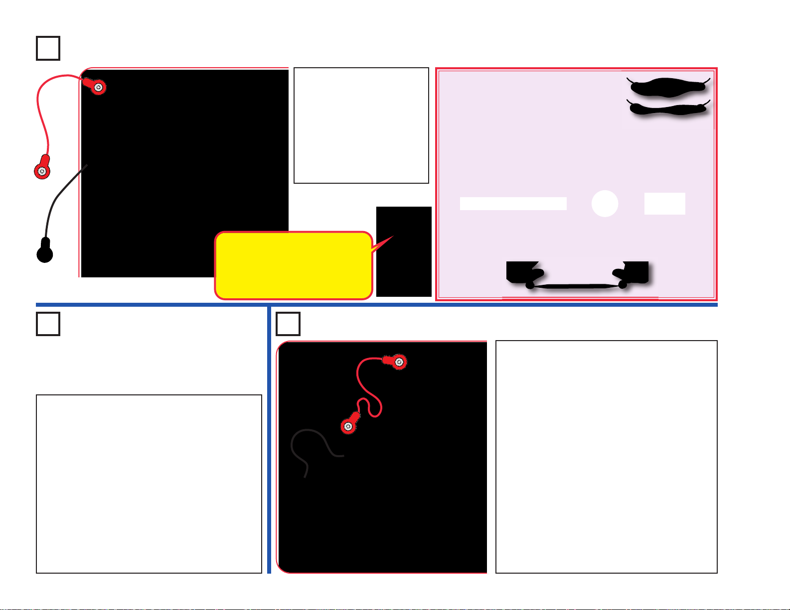
-67-
Method A (easy): Spread some water on the
table into puddles of different shapes, perhaps
like the ones shown here. Touch the jumper
wires to points at the ends of the puddles.
Method B (challenging): Use a SHARP pencil (No. 2 lead is best)
and draw shapes, such as the ones here. Draw them on a hard, flat
surface. Press hard and fill in several times until you have a thick,
even la yer of pencil lead. Touch the jumper wires to points at the ends
of the drawings. You may get better electrical contact if you wet the
metal with a few drops of water. Wash your hands when finished.
Method C (adult supervision and permission required): Use
some double-sided pencils if available, or VERY CAREFULLY break
a pencil in half. T ouch the jumper wires to the blac k core of the pencil
at both ends.
Project 145 Musical Shapes
Long, narrow shapes have more
resistance than short, wide ones.
The black core of pencils is
graphite, the same material used
in the resistors in the pivot stand.
Build the circuit and turn on
the switch (S1). Make your
parts using either the water
puddles method (A), the
drawn parts method (B), or
the pencil parts method (C).
Touch the metal in the
jumper wires to your parts
and read the current.
Use the preceding circuit but touch the metal in
the jumper wires snaps with your fingers. Wet
your fingers for best results. Your fingers will
change the sound, because your body resistance
is less than the 100kΩ resistor (R5) in the circuit.
Next, place the loose ends of the jumper wires in
a cup of water, make sure the metal parts aren’t
touching each other. The water should change
the sound.
Now add salt to the water and stir to dissolve it.
The sound should have higher pitch now, since
salt water has less resistance than plain water.
Don’t drink any water used here.
Project 146
Human & Liquid
Sounds
Build the circuit and turn on the switch (S1).
Touch the metal in the jumper wire snaps with
your fingers. Use the lever on the adjustable
resistor (RV) to adjust the sensitivity of the
circuit. You may see a difference in the light
brightness just by pressing the contacts harder
with your fingers.
Next, place the loose ends of the jumper wires
in a cup of water, make sure the metal par ts
aren’t touching each other. The water should
change the light brightness. Readjust sensitivity
using RV.
Now add salt to the water and stir to dissolve it.
The light should be brighter, since salt water has
less resistance than plain water. Readjust
sensitivity using RV.
Don’t drink any water used here.
Project 147 Human & Liquid Light
Page 69

-68-
Project 148 Blow On the Light
Project 149 Blow Off the Light
Build the circuit and turn on the slide
switch (S1). Set the le ver on the adjustab le
resistor (RV) to the top. If the white LED
(D6) is on, move the lever on RV until the
LED just shuts off. Now blow on the
microphone (X1) to turn the white LED on.
The microphone is a resistor
that changes in value due to
changes in air pressure on its
surface.
Build the circuit and turn on the slide switch (S1). W ait f or the white LED
(D6) to come on. Blo w into the microphone (X1) to make the white LED
flicker. If you blow hard enough, the LED will turn off for a moment.
Page 70

-69-
Project 150 Transistor
Project 151 Another Transistor
Build the circuit and turn on the slide switch (S1). Slo wly mov e the lev er
on the adjustable resistor (RV) across its range while watching the
brightness of the red & white LEDs (D1 & D6).
This circuit is just like the preceding one,
except uses a different type of tr ansistor .
Build the circuit and turn on the slide
switch (S1). Slowly mo ve the le v er on the
adjustable resistor (R V) across its r ange
while watching the brightness of the red
& white LEDs (D1 & D6).
Transistors, such as the NPN transistor (Q2),
can amplify electric currents. In this circuit,
the adjustable resistor controls a small
current going to the transistor through the
red LED. The transistor uses this small
current to control a larger current through the
white LED. At some RV settings, the control
current is too small to light the red LED, but
the transistor-amplified is large enough to
light the white LED.
The PNP transistor (Q1) is just like
the NPN transistor (Q2), except that
the currents flow in opposite
directions.
Page 71
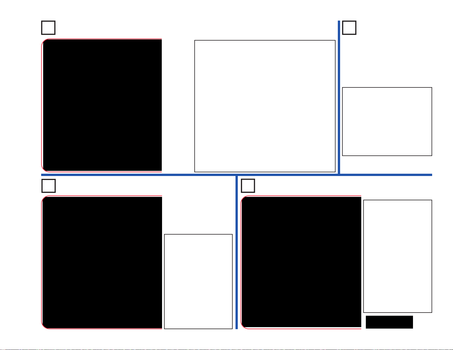
-70-
Project 155 Mini Battery
Project 154
Modify the project 152
circuit to be this one,
which has the
adjustable resistor (RV)
instead of the 5.1kΩ
resistor (R3). Use the
lever on R V to adjust the
capacitor charge &
discharge rate, setting it
towards the red LED
(D1) will make the LEDs
flash brighter but get
dim faster.
Charging & Discharging
Project 153
Mini
Capacitor
Use the project 152 circuit but
replace the 100µF capacitor
(C4) with the 0.1µF capacitor
(C2). The circuit works the same,
but the LEDs will only light very
briefly, because the smaller
0.1µF capacitor stores much
less electricity than the larger
100µF capacitor.
Project 152
Turn on the slide switch (S1) for a few seconds, then
turn it off. The red LED (D1) is dimly lit for a few
moments but goes completely dark as the batteries
(B1) charge up the 100µF capacitor (C4). The
capacitor is storing electrical charge.
Now press the press switch (S2) for a few seconds.
The white LED (D6) is initially bright but goes dim as
the capacitor discharges itself through it.
The C4 capacitor value (100µF) sets how much
charge can be stored in it, and the R3 resistor value
(5.1kΩ) sets how quickly that charge can be stored or
released.
Now swap the locations of the white & red LEDs, and
try the circuit again. Both LEDs have the same
electrical current flowing through them, but white LED
is much brighter than the red LED because it is a
super-bright LED while the red one isn’t.
Adjustable
Charging &
Discharging
This circuit is similar to the
preceding one, but may be
easier to understand. Set the
lever on the adjustable resistor
(RV) towards the 100µF
capacitor (C4). Place the white
LED (D6) across the points
marked B & C; the LED lights
as the capacitor charges.
Next, place the white LED
across points A & B instead;
now the LED lights as the
capacitor discharges. Move
the white LED back to B & C
and repeat. Use the lever on
RV to vary the charge /
discharge rate.
The capacitor is storing
energy like a mini battery.
Page 72
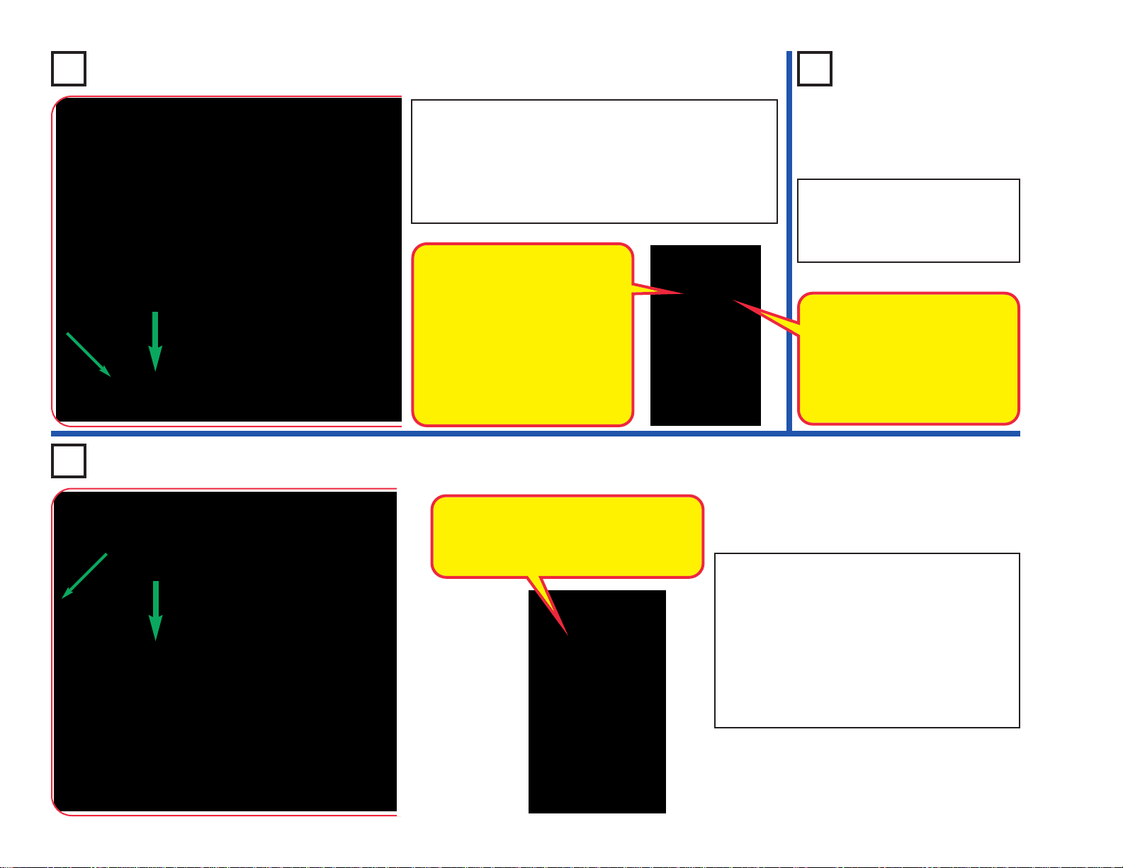
-71-
Photo Current Amplifier
Project 157
LEDs &
Transistors
Use the preceding circuit but
replace either LED (D6 or D8)
with the red LED (D1). Compare
all three LEDs, in both locations.
Project 156
Build the circuit, turn on the switch (S1), and vary the
amount of light on the phototransistor (Q4) using your
hand. Compare the brightness of the white LED (D6)
and color LED (D8).
Swap the locations of the white and color LEDs, and
compare the brightness now.
Project 158 PNP Amplifier
This circuit is just like the preceding one
except it uses a different type of transistor.
Build the circuit, turn on the switch (S1), and
vary the amount of light on the phototransistor
(Q4) using your hand. Compare the brightness
of the white LED (D6) and color LED (D8).
Replace either LED (D6 or D8) with the red
LED (D1). Compare all three LEDs, in both
locations.
The NPN transistor (Q2) is a current
amplifier. When a small current flows
into Q2 through the left branch
(through Q4), a larger current will
flow into Q2 through the right branch
(with R1). Green arr ows sho wn the
current flow. So the LED on the
right side will be brighter than the
LED on the left side. The current in
the right branch might be 100 times
larger than in the left branch.
LED brightness depends on the
materials used, construction
quality , and the current through it.
The white LED is super-bright,
the red LED is low-brightness,
and the color LED is between the
others.
The PNP transistor (Q1) is just like the
NPN transistor (Q2), except that the
currents flow in opposite directions.
Green arrows shown the current flow.
Page 73
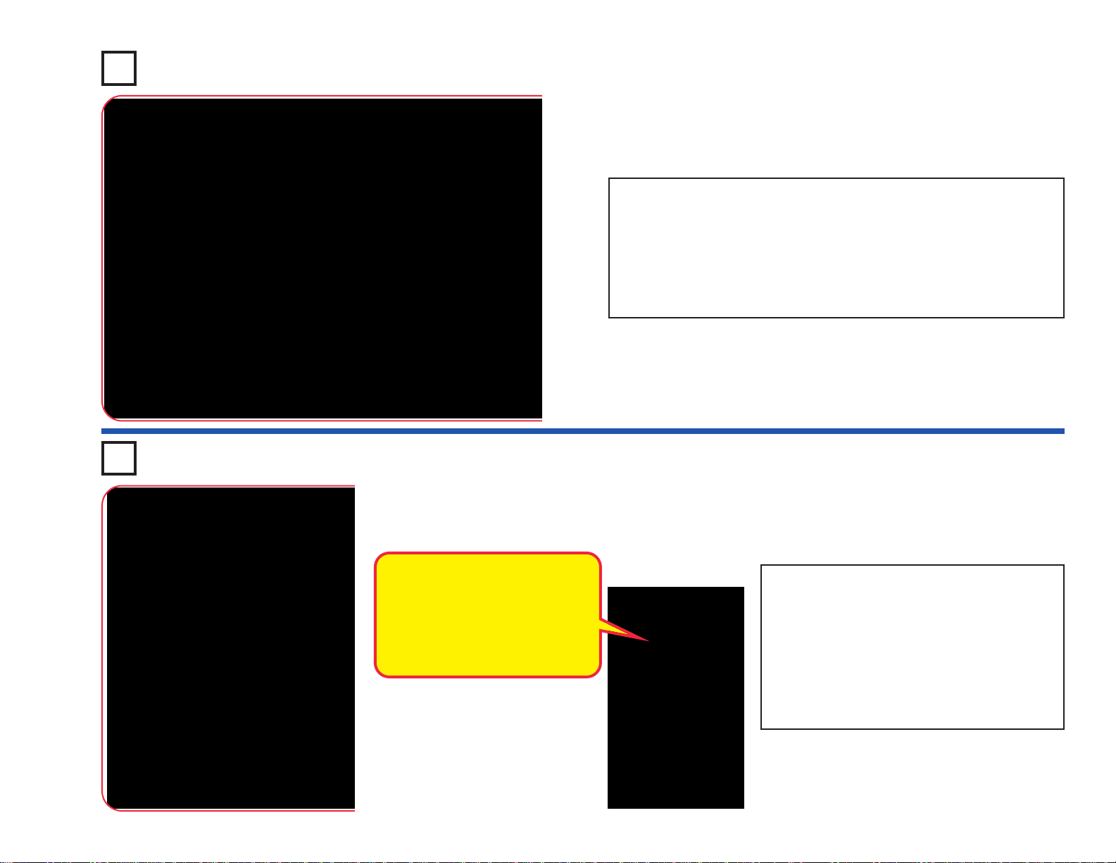
-72-
Project 159 Photo Control
Project 160 Resistance Director
Set the lever on the adjustable resistor (RV) all the way towards the
press switch (S2). Turn on the slide switch (S1), and push the press
switch. The color LED (D8) will light for a while and then slowly turn off.
The brighter the light on the phototransistor (Q4), the shorter the color
LED stays on.
You can replace the color LED with the red LED (D1) or the white LED
(D6).
Move the le v er on the adjustab le resistor (RV)
across its range and watch the brightness of
the white and color LEDs (D6 & D8).
Replace either LED with the red LED (D1) and
compare it too.
You can also replace one of the battery
holders (B1) with a 3-snap wire, and compare
the LED brightnesses at lower voltage.
The adjustable resistor can be
adjusted from about 200 ohms to
about 50,000 ohms.
The white LED is a super-bright
LED, so will be brighter than the
others at comparable resistance.
Page 74

-73-
Project 161 Current Controllers -
Series
Project 162 Current Controllers -
Parallel
Turn on either or both switches (S1 & S2) and
compare the white LED (D6) brightness.
This circuit has the 100Ω resistor (R1), the 5.1kΩ
resistor (R3), and the 100kΩ resistor (R5)
arranged in series. The switches are used to
bypass the larger resistors. The largest resistor
controls the brightness in this arrangement.
Turn on either or both switches (S1 & S2) and compare the white LED
(D6) brightness.
This circuit has the 100Ω resistor (R1), the 5.1kΩ resistor (R3), and the
100kΩ resistor (R5) arranged in parallel. The switches are used to
disconnect the smaller resistors. The smallest resistor controls the
brightness in this arrangement.
Resistors are used to control the
amount of current through a
circuit. Increasing the resistance
decreases the current.
Page 75

-74-
Project 163 Blow Sound Changer
When you turn on the switch (S1), you hear a siren sound. Blow into
the microphone (X1) to change the sound.
RV is used as a fixed resistor (50kΩ); so moving its control lever will
have no effect.
Short Light
Project 165
Shorter
Light
Use the preceding
circuit but replace the
100kΩ resistor (R5)
with the smaller 5.1kΩ
resistor (R3). Now the
light doesn’t stay on as
long.
Project 164
Build the circuit, turn on the slide
switch (S1), and push the press
switch (S2). The white LED (D6)
is on for a while and then shuts
off. Turning S1 off and back on
will not get the light back on.
Push S2 to get the light back on.
Replace the white LED with the
color LED (D8) to change the
light style.
RV is used as a fixed resistor
(50kΩ); so moving its control
lever will have no effect.
The light is on while the
100µF capacitor (C4) is
charging, and shuts off when
the capacitor gets fully
charged. Pressing S2
discharges the capacitor. The
charge-up time is set by the
capacitor’s value and
resistors R5 and RV.
Page 76
-75-
Project 167
Air Pressure Light Control
Project 166
Photo Light Control
Turn on the switch (S1).
Control the white LED
(D6) brightness by
varying the amount of
light on the phototransistor (Q4). Try
holding the red, green,
and blue filters over the
phototransistor and see
how they affect it.
Replace the white LED
with the red LED (D1) or
the color LED (D8) and
compare them.
Blow on the microphone (X1).
The white LED (D6) will flicker ,
because the resistance of the
microphone changes when
you blow on it.
Talking into the microphone
also changes its resistance,
but you will not be able to
notice the difference here.
You can replace the white LED
with the red LED (D1) or the
color LED (D8), but they will
not be very bright.
Project 168 Slow On, Slower Off
Turn on the slide switch (S1), nothing happens. Now push the press
switch (S2) and hold it down. The color LED (D8) takes a few seconds
to turn on, then will very slowly get dim after S2 is released. The
adjustable resistor (RV) controls the shut-off time.
You can replace the color LED with the red LED (D1) or the white LED
(D6).
The phototransistor
uses light to control
electric current. As
more light shines on
the phototransistor,
the current through
it increases, making
the LED brighter.
The 100µF capacitor (C4) controls the color LED
through the PNP transistor (Q1). Pressing S2 quickly
charges up the capacitor, and releasing S2 allows the
capacitor to slowly discharge. Capacitors can store
electric charge and release it when needed, so they
are often used in timing circuits like this.
Page 77

Project 169
Delayed Photo Speed Control
Project 170
Delayed
Speed
Control
Use the preceding circuit,
but replace the 100µF
capacitor (C4) with the
much smaller 0.1µF
capacitor (C2). Now
varying the light to the
phototransistor has only a
small effect on the motor
speed.
Turn on the switch (S1), the motor (M1)
spins. As you move your hand over the
phototransistor (Q4), the motor slows.
Cover the phototransistor with your hand.
The motor slows down and may stop, but
will speed up in a few seconds. Also try
shining a flashlight into the phototransistor.
!
WARNING: Moving
parts. Do not touch the
fan or motor during
operation.
Use the circuit from project 169, but replace the
phototransistor (Q4) with the microphone (X1, “+”
on top). Clap, talk loudly, or blow into the
microphone to change the motor speed.
Project 171
Delayed Speed Control (II)
Use the circuit from project 169, but swap the
locations of the phototransistor (Q4) and 5.1kΩ
resistor (R3); put “+” on Q4 towards C4. Now
increasing the light to the phototransistor slows
down the motor, instead of speeding it up.
Project 172
Audio Delayed Speed Control
Project 173
Photo Speed Control
Turn on the switch (S1), and set the adjustable resistor (RV) so the motor (M1) just spins . Slowly
cover the phototransistor (Q4) and the motor spins f aster . Place more light on the phototr ansistor
and the motor slows down.
!
WARNING:
Moving parts. Do
not touch the fan
or motor during
operation.
-76-
Page 78

-77-
Project 174 Light Buzz
Project 175 Delay Lights
Turn on the switch (S1). If there is enough light on the phototransistor
(Q4), then nothing will happen. Cover the phototransistor with your
finger, now the speaker (SP) makes noise and the color LED (D8)
flashes. Wave your fingers over the phototransistor to vary the sound.
Replace the color LED with the red or white LEDs (D1 & D6). The light
and sound will be a little different.
Turn on the slide switch (S1), and push the press switch (S2). The color
and white LEDs (D6 & D8) come on slowly but will stay bright for a long
time after you release the press switch. Connect the red jumper wire
across points A & B if you get tired of waiting for the LEDs to turn off.
Replace the 5.1kΩ resistor with the 100kΩ resistor. Now you have to
push the press switch for much longer to make the LEDs bright.
Replace the 100µF capacitor (C4) with the smaller 0.1µF capacitor
(C2). No w the LEDs turn on and off much faster, because C2 does not
store as much electricity as C4.
Page 79

-78-
Project 177
Narrow Range Tone
Project 176 Touch Light
Build the circuit. It doesn’t do
anything, and may appear to be
missing something. It is missing
something, and that something is
you.
Touch points A & B with your
fingers. The white LED (D6) may be
lit. If isn’t bright, then you are not
making a good enough electrical
connection with the metal. Try
pressing harder on the snaps, or
wet your fingers with water or
saliva. The LED should be bright
now . You can replace the white LED
with the red or color LEDs (D1 &
D8).
Turn on the switch (S1)
and move the lever on
the adjustable resistor
(RV) around. The circuit
makes a tone sound, but
only over a small range
of settings on RV.
Replace the 100kΩ
resistor (R5) with the
5.1kΩ resistor (R3). The
tone is a little different
now.
Project 178 Slow Off Lights
Turn on the slide switch (S1), and push the press switch (S2). The red
and color LEDs (D1 & D8) stay on for a f ew seconds after you release
the press switch.
You can change how long the LEDs stay on f or b y replacing the 100µF
capacitor with the 0.1µF capacitor, b y replacing the 100kΩ resistor (R5)
with the 5.1kΩ resistor (R3), or by removing the 100kΩ resistor.
For more fun, try swapping the locations of the LEDs, or replacing either
with the white LED (D6).
Page 80

-79-
Project 179 3D Pictures
Look at the pictures here; they probably look blurry. Now place
the red filter in front of your left eye and the blue filter in front of
your right eye, and look at the pictures again. Now the pictures
look clearer, and you can see them in three dimensions (3D).
These pictures contain separate red &
blue images, taken from slightly diff erent
viewpoints, combined together. When
you view them through the red & blue
filters, each eye sees only one image.
Your brain combines the two images
into the single picture that you “see”, b ut
the differences between the two images
make the combined picture seem threedimensional.
How 3D works:
Most people have two eyes, spaced
about 2 inches apart. So each eye sees
the world a little differently, and your
brain uses the difference in views to
calculate distance. For each object in
view , the greater the diff erence between
the two scenes, the closer it must be. If
you close one eye, you will have a
harder time judging distance – try
catching a ball with just one eye! (Be
sure to use a soft ball if you try playing
catch with one eye.)
When you watch a 3D movie in a
theater, you wear 3D glasses so that
each eye will see a diff erent image . The
movie screen actually shows two
images, and the glasses filter them so
that only one image enters each eye.
Most movie theaters use polarized
images and glasses with polarized
lenses, so that each eye sees a diff erent
image.
Another way to make 3D is using red &
blue images, then view using glasses
with red & blue filters, as you are doing
in this project. Unf ortunately this method
does not give you the color quality that
the polarization method has.
Page 81

-80-
Project 180 Super Infrared Detector
You need an infrared remote
control for this project, such as
any TV/stereo/DVD remote
control in your home.
Build the circuit. The red LED
(D1) will be dim. Tur n on the
switch (S1). Point your remote
control toward the infrared
module (U24) and press any
button to activate the white
LED (D6). Once activated, the
white LED stays on until the
switch is turned off.
Note: This circuit can activate
without a remote control, due
to infrared in sunlight or some
room lights. If this happens, try
moving to a dark room.
Remote
Infrared light can be given off by anything
warm. Sunlight and room lights emit some
infrared light, in addition to visible light. This
circuit is very sensitive, and may often be
activated without a remote control. TV remote
control receivers look for a sequence of pulses
that identify an infrared message directed to
their TV set model, so will not be activated by
sunlight or room lights.
3D Pictures
Page 82

-81-
Project 181 Infrared Optical Audio
You need an infrared remote control for this project,
such as any TV/stereo/DVD remote control in your
home.
Build the circuit as shown. Place the clear cable holder
on the white LED (D6) and the black cable holder on
the phototransistor (Q4), then place the fiber optic cable
into the holders as far as it will go. For best performance
the fiber optic cable should stand straight up in the
holders, without bending them.
Turn on the switch (S1). Point your remote control
toward the infrared module (U24) and press any b utton
to activate the white LED (D6). Light is transmitted from
the white LED, through the fiber optic cable, to control
the strobe IC (U23) and speaker (SP).
The motor (M1) is used as a 3-snap here, and will not
spin. Sometimes this circuit may activate without a
remote control, due to infrared in sunlight or some room
lights. You may get better results in a dark room.
Project 182 Test the Color Organ
This project tests the features of the color organ (U22), and will be referenced b y
the Advanced Troubleshooting section on page 15.
A. Build the circuit, and turn on the switch (S1). The light on top of the color organ
should be changing colors.
B. Remov e the 0.1µF capacitor (C2), add a 2-snap across the points marked Y &
Z, and reset the circuit by turning it off and on using the switch. Connect the
red jumper wire between the point marked “X”, and points marked “R”, “G”, or
“B” in the drawing. Touching R should make the light red, G should make it
green, and B should make it blue.
C. Remove the 2-snap that was added across points Y & Z. Connect a music
device (not included) and headphones (optional, and not included) to the color
organ as shown, and start music on it. Set the volume control on your music
device so that the light on the color organ is changing (the light will not change
if your volume is set too high or too low).
MP3
player
Headphones (Optional)
Remote
Black
Clear
Page 83

-82-
OTHER SNAP CIRCUITS®PRODUCTS!
For a listing of local toy retailers who carry Snap Circuits®visit www.elenco.com or call us toll-free at 800-533-2441. For Snap Circuits
®
upgrade kits, accessories, additional parts, and more information about your parts visit www.snapcircuits.net.
Build over 100 projects
Including:
Snap Circuits®Jr.
Model SC-100
• Flying saucer
• Spin draw
• Sound activated switch
• Alarm circuit
Contains over 30 parts
Including:
• Photoresistor
• Motor
• Music IC
• Space War IC
Build over 300 projects
Including:
Snap Circuits
®
Model SC-300
• AM radio
• Radio announcer
• Lie detector
• Burglar alarm
Contains over 60 parts
Including:
• T wo transistors
• Microphone
• Power amplifier IC
• Variable capacitor
Build over 500 projects
Including:
Snap Circuits®Pro
Model SC-500
• Digitally tuned FM radio
• Adjustable light control
• Digital voice recorder
• AC generator
Contains over 75 parts
Including:
• Recording IC
• FM module
• T ransf ormer
• Analog meter
Build over 750 projects
Including:
Snap Circuits®Extreme
Model SC-750
• Strobe light
• Transistor AM radio
• Electromagnetism
• Rechargeable battery
Contains over 80 parts
Including:
• Solar cell
• Electromagnet
• Vibration switch
• Computer interface
Snap Circuits®Green
Model SCG-125
Build over 75 projects
Projects relate to electricity in the home and
magnetism and how it is used.
Snaptricity
®
Model SCBE-75
Contains over 40 parts
Including:
Meter, electromagnet, motor, lamps, switches,
fan, compass
, and electrodes.
Alternative Energy Kit
Build over 125 projects and have loads of fun learning
about environmentally-friendly energy and how the
electricity in your home works. Includes full-color manual
with over 100 pages and separate educational manual.
This educational manual will explain all the forms of
environmentally-friendly energy including: geothermal,
hydrogen fuel cells, wind, solar, tidal, hydro, and others.
Contains over 40 parts.
Snap Rover
®
Model SCROV-10
Deluxe Snap Rover
®
Model SCROV-50
Features:
• Disc shooter
• Digital voice recorder
• Music sounds
• Goes forward &
backward
• Headlight
• Red & blue side lights
• Wireless remote control
• Left & right turning
control
Contains over 60 projects
and over 50 parts
Have FUN building y our own RC Snap Rov er
TM
using the colorful Snap Circuits®parts that
come with this kit. There is no soldering
required as all the parts snap together with
ease. Once completed, you will be able to
navigate your surroundings with the easy-touse Snap Rover
TM
remote control.
Contains over 20 projects
and over 30 parts
Page 84

SCL-175 LIGHT Block Layout
Important: If any parts are missing or damaged, DO NOT RETURN TO RETAILER.
Call toll-free (800) 533-2441 or e-mail us at: help@elenco.com. Customer Service • 150 Car penter Ave.
Wheeling, IL 60090 U.S.A.
Note: A complete parts list is on pages 2 and 3 in this manual.
 Loading...