

Page 1
WARNING: Always check your wiring before
urning o n a c ircuit. Never leave a ci rcuit
t
unatte nded while the batteries are i nstalle d.
ever connect additional batteries or any other
N
power sources to your circuits.
LED Fun
CAUTION: High intensity light. Do not look
irectly at the white or blue LEDs (D6 & D9).
d
Model SCP-11
ARNING: SHOCK HAZARD -
W
Never connect Snap Circuits
to the electrical outlets in your
ome in any way!
h
®
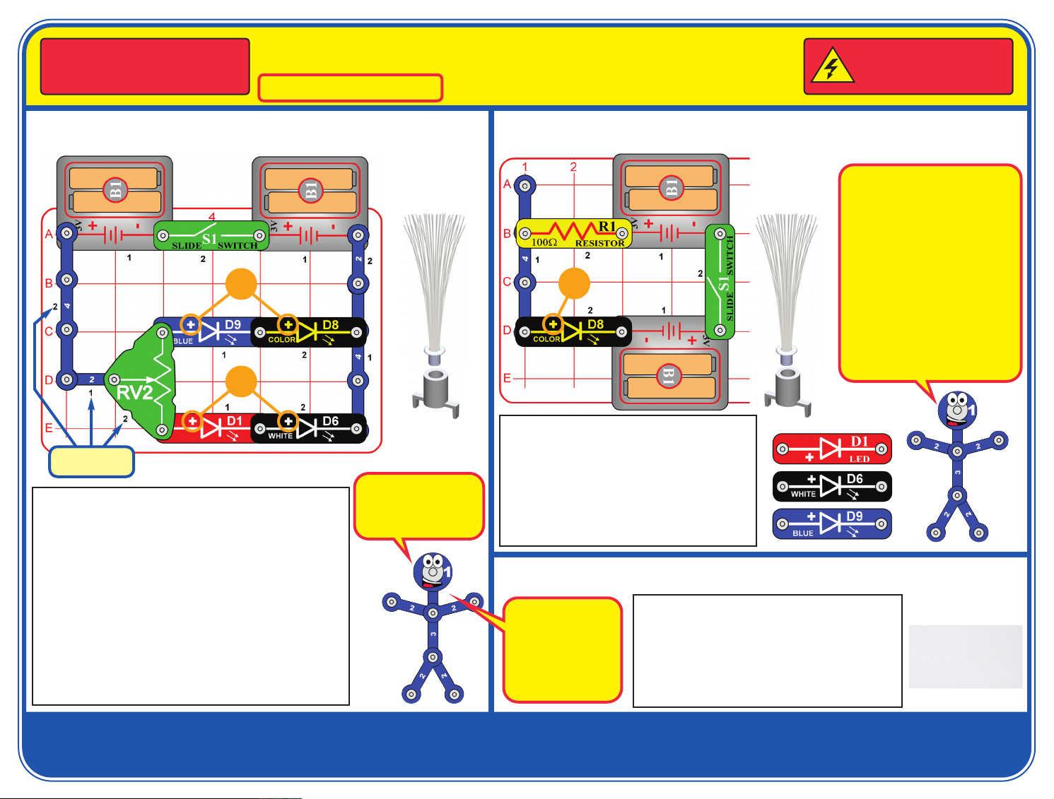
Project 1 Light Slider
Place fiber optic
tree & mounting
ase on any LED
b
+
+
Placement
Level Numbers
Snap Circuits®uses electronic blocks that snap onto a
base grid to build different circuits. These blocks have
different colors and numbers on them so that you can
easily identify them. Build the circuit shown by placing all
the parts with a black 1 next to them on the clear base
grid first. Then, assemble parts marked with a 2. Install
two (2) “AA” batteries (not included) into each of the
battery holders (B1). Lay the mounting base on any LED
(D1, D6, D8, or D9) and place the fiber optic tree in it.
Turn on the slide switch (S1). Move the lever on the
adjustable resistor (RV2) around to change the
brightness of the LEDs. The blue & color LEDs will be
blinking. For best effects, place the circuit in a dimly lit
room. Also, try swapping the the LEDs with each other.
This circuit is pictured
on the front of the box,
use that picture to help
in building it.
Project 2 Color Light
+
Build the circuit as shown, and turn on the
slide switch (S1). The color LED (D8) is
changing colors in a repeating pattern. If
desired, place the fiber optic tree and
mounting base on the color LED. For best
effects, place the circuit in a dimly lit room.
Next, replace the color LED (D8) with the red,
white, or blue LEDs (D1, D6, & D9).
Project 3 Spectrum of Light
Prismatic film separates light into
different colors, and
can make interesting
light effects. White
light is a combination
of all colors.
Use the circuit from project 2, but look at each of
the LEDs through the prismatic film. Prismatic
film is the approximately 1.5” x 1” plastic sheet
that is included in this kit. The white LED will give
the most impressive effects. Next, view different
light sources in and around your home through
the prismatic film.
f desired, place
I
fiber optic tree
mounting base
&
on color LED
The batteries (B1) push electricity
through the circuit. The switch
(S1) turns the electricity on or off.
Resistors (like R1) limit and
control the flow of electricity.
LEDs are light emitting diodes,
which convert electrical energy
into light; the color of the light
emitted depends on the
characteristics of the material
used in them. LEDs are more
energy efficient than normal light
bulbs. The color LED contains
red, green, and blue LEDs, with a
micro-circuit controlling them.
Prismatic film
If you have any problems, contact Elenco
®
Copyright © 2014 Elenco®Electronics, Inc. All Rights Reserved. ● 150 Carpenter Ave. ● Wheeling, IL 60090
(800) 533-2441 Fax: (847) 520-0085 ● e-mail: elenco@elenco.com ● Website: www.elenco.com or www.snapcircuits.net
753160
Page 2

Project 4 Adjustable Light
Project 6
+
If desired, place
fiber optic tree
mounting base
&
n color LED
o
Build the circuit as shown, and turn on the
slide switch (S1). Move the lever on the
adjustable resistor (RV2) to vary the
brightness of the color LED (D8). If
desired, place the fiber optic tree and
mounting base on the color LED. For best
effects, place the circuit in a dimly lit room.
Next, replace the color LED (D8) with the
red, white, or blue LEDs (D1, D6, & D9).
Project 5 Row of Lights
Red light is easier for LEDs to produce
than the other colors. When all the LEDs
are connected in parallel like they are
here, the red LED will dominate because
it turns on more easily. Resistor R1 limits
the flow of electricity from the batteries,
and the red LED takes most of it. The
other LEDs may not get enough
electricity, especially when there is only
one set of batteries. When electricity is
limited, the color LED can make red light
more easily than other colors.
Adjustable Row of Lights
Use the project 5 circuit but replace the 100W
resistor (R1) with the adjustable resistor
(RV2), connected as shown. Move the lever
on RV2 around and compare the circuit to
project 5. Try using only two or three of the
LEDs at once.
RV2 has higher resistance on all settings than
R1 did, which limits the flow of electricity much
more than in project 5. RV2 can be adjusted
from 200W to 10,000W.
Project 7 Blinking Colors
When the red and
white LEDs are
connected in
parallel (which
happens when S1
is on), the red
LED will dominate
because it turns
on more easily.
The blue LED will
perform similarly
to the white LED.
The switch (S1) isn’t used here, so this circuit will always be on. The red LED (D1) will be bright,
but the brightness of the other LEDs (D6, D8, & D9) may vary. If you remove the red LED from
the circuit then the others get brighter. For best effects, take the circuit into a dimly lit room.
Place the fiber optic tree on one LED if desired.
Now replace one of the battery holders (B1) with the switch (S1), and turn it on. The red LED is
bright, the blue & white LEDs may be dim or off, and the color LED may only be flashing red.
Now remove the red LED from the circuit and see if the others get brighter.
Leave the swtich (S1) off at first; the white and color
LEDs (D6 & D8) are blinking. Now turn on the switch;
the red LED (D1) is blinking but the white LED is off.
If you swap the locations of the red and white LEDs,
then the red LED will be blinking and the white LED will
be off, and turning on the switch won’t change anything.
Try replacing any of the LEDs with the blue LED (D9),
or swapping any of them with the color LED.
Page 3

Project 8 Double Light Project 10 Series of Lights
This circuit has the LEDs connected in a
series (not in parallel, as in project 5). This
+
arrangement makes the LEDs dimmer, but
makes the batteries last longer.
By using different materials and
manufacturing processes, LEDs can be made
for different brightness and for wide/narrow
angles of view. The red LED is not as bright
as the others, and can be viewed from a wider
angle; LEDs like this might be used as
indicators. The white LED is very bright
especially when looking dirrectly at it; LEDs
like this might be used in flashlights.
+
Turn on the switch (S1). The red & blue LEDs (D1 & D9) will be
on. Try replacing either or both of them with the white and color
LEDs (D6 & D8); try all combinations. If the color LED is used
then both will be blinking. For best effects, take the circuit into a
dimly lit room. Place the fiber optic tree on one LED if desired.
LEDs are like special
one-way light bulbs.
They have a “turn-on
threshold” of voltage
(about 1.5V for red,
2.0V for green, and
3.0V for blue or white)
that must be exceeded
before light is produced,
brightness then depends on the circuit
resistance. This circuit
has 3 LEDs in series, so
the battery voltage must
exceed all of their turnon thresholds before
any light is produced.
Turn on the switch (S1). The LEDs (D1, D8, & D9) will be
dim, and some may not light at all. Try viewing them in a
dimly lit room. You can replace the blue LED with the white
LED (D6), but if you replace the others then none may light.
Project 9
Adjustable Double Light
Use the project 8 circuit but replace the 100W
resistor (R1) with the adjustable resistor
(RV2), connected as shown. Move the lever
on RV2 around and compare the circuit to
project 8, with all combinations of LEDs.
What is Resistance? Take
your hands and rub them
together very fast. Your
hands should feel warm.
The friction between your
hands converts your effort
into heat. Resistance is the
electrical friction between an
electric current and the
material it is flowing through.
Project 11 Brightness Comparator
In building the circuit, note that
one of the 4-snap wires is
partially beneath the adjustable
The white LED is
the brightest LED,
due to its material
and manufacturing
process.
resistor (RV2) and one of the
battery holders (B1). Turn on the
switch (S1) and move the lever
on the adjustable resistor around.
Compare the brightness of the
LEDs (D1 & D6), then replace
either or both of them with the
blue and color LED (D8 & D9).
Try all LED combinations. For
best effects, place the circuit in a
dimly lit room.
Page 4

OTHER SNAP CIRCUITS®PRODUCTS! PARTS LIST
Contact Elenco®to find out where you can purchase these products.
Snap Circuits®Jr. Model SC-100
Build over 100 projects, contains over 30 parts.
Snap Circuits®Green Model SCG-125
Build over 125 projects, contains over 40 parts.
Flying Saucer Plus
Model SCP-09
Basic Electricity
Model SCP-10
Build over 175 projects, contains over 55 parts.
Snap Circuits®Sound Model SCS-185
Build over 185 projects, contains over 40 parts.
FM Radio
Model SCP-12
Snap Circuits®Light Model SCL-175
Motion Detector
Model SCP-13
Strobe Light & Sound
Model SCP-14
Qty. ID Name Part #
r 2 2 2-snap wire 6SC02
r 2 4 4-snap wire 6SC04
r 2 B1 Battery holder 6SCB1
r 1 Base grid 6SCBGMF
r 1 D1 Red LED 6SCD1
r 1 D6 White LED 6SCD6
r 1 D8 Color LED 6SCD8
r 1 D9 Blue LED 6SCD9
r 1 Prismatic film 6SCFILM
r 1 Fiber optic tree 6SCFT
r 1 Mounting base 6SCFMB
r 1 R1 100W resistor 6SCR1
r 1 RV2
Adjustable resistor
6SCRV2
r 1 S1 Slide switch 6SCS1
Important: If any parts are missing or
damaged, DO NOT RETURN TO
RETAILER. Call toll-free (800) 533-2441 or
e-mail us at: help@elenco.com.
Customer Service ● 150 Carpenter Ave. ●
Wheeling, IL 60090 U.S.A.
You may order additional / replacement
parts at our website: www.snapcircuits.net
BATTERIES:
● Use only 1.5V AA type, alkaline
batteries (not included).
● Insert batteries with correct polarity.
● Non-rechargeable batteries should not
be recharged. Rechargeable batteries
should only be charged under adult
supervision, and should not be
recharged while in the product.
● Do not mix alkaline, standard (carbonzinc), or rechargeable (nickelcadmium) batteries.
● Do not mix old and new batteries.
Remove batteries when they are used up.
●
● Do not short circuit the battery
terminals.
● Never throw batteries in a fire or
attempt to open its outer casing.
● Batteries are harmful if swallowed, so
keep away from small children.
 Loading...