

Page 1
Copyright © 2009 by Elenco®Electronics, Inc. All rights reserved. No part of this book shall be reproduced 753317
by any means; electronic, photocopying, or otherwise without written permission from the publisher.
Page 2
The battery (B4) will only work if it is charged. Project 3 shows how to recharge it.
Table of Contents For the best learning experience, do the projects in order.
Basic Troubleshooting 1
Parts List 2
How to Use It 3, 4
About Your Snap Circuits®Green Parts 5 - 7
Advanced Troubleshooting 9, 10
Project Listings 11, 12
Projects 1 - 129 13 - 77
Other Snap Circuits®Projects 78
DO’s and DON’Ts of Building Circuits 8
WARNING FOR ALL PARTS WITH A SYMBOL - Moving parts. Do not touch the
motor or fan during operation. Do not lean over the motor. Eye protection is
!
recommended.
WARNING: SHOCK HAZARD - Never
connect your Snap Circuits®set to the
electrical outlets in your home in any way!
!
!
WARNING: CHOKING
HAZARD - Small parts. Not
!
for children under 3 years.
Conforms to all
applicable U.S.
government
requirements.
Basic Troubleshooting
T
1.
2. Most circuit problems are due to incorrect assembly, always double-check that your circuit
exactly matches the drawing for it.
3. Be sure that parts with positive/negative markings are positioned as per the drawing.
4. Be sure that all connections are securely snapped.
5. Sometimes the motor or solar cell is omunted on the pivot stand so its angle to the sun or
wind can be adjusted. The pivot stand base, post, and top should be assembled together.
Elenco®Electronics is not responsible for parts damaged due to incorrect wiring.
Note: If you suspect you have damaged parts, you can follow the Advanced Troubleshooting
procedure on page 9 to determine which ones need replacing.
Warning to Snap Circuits®Owners: Use only
parts included in this kit to prevent damage.
WARNING: If you have long
hair, be careful that it does not
!!
get caught in the fan blade.
WARNING: Always check your
wiring before turning on a circuit.
Never leave a circuit unattended
while the batteries are installed.
Never connect additional
batteries or any other power
sources to your circuits. Discard
any cracked or broken parts.
Batteries:
!
• Do not short circuit the
battery terminals.
• Never throw batteries in a fire
or attempt to open it.
• Use only 1.5V AAA type
(not included) in the FM radio.
• Insert batteries with correct
polarity.
• Non-rechargeable batteries
should not be recharged.
• Do not mix alkaline, standard
(carbon-zinc), or rechargeable
(nickel-cadmium) batteries.
• Do not mix old and new
batteries.
• Remove batteries when they
are used up.
• Batteries are harmful if
swallowed, so keep away
from small children.
-1-
Page 3
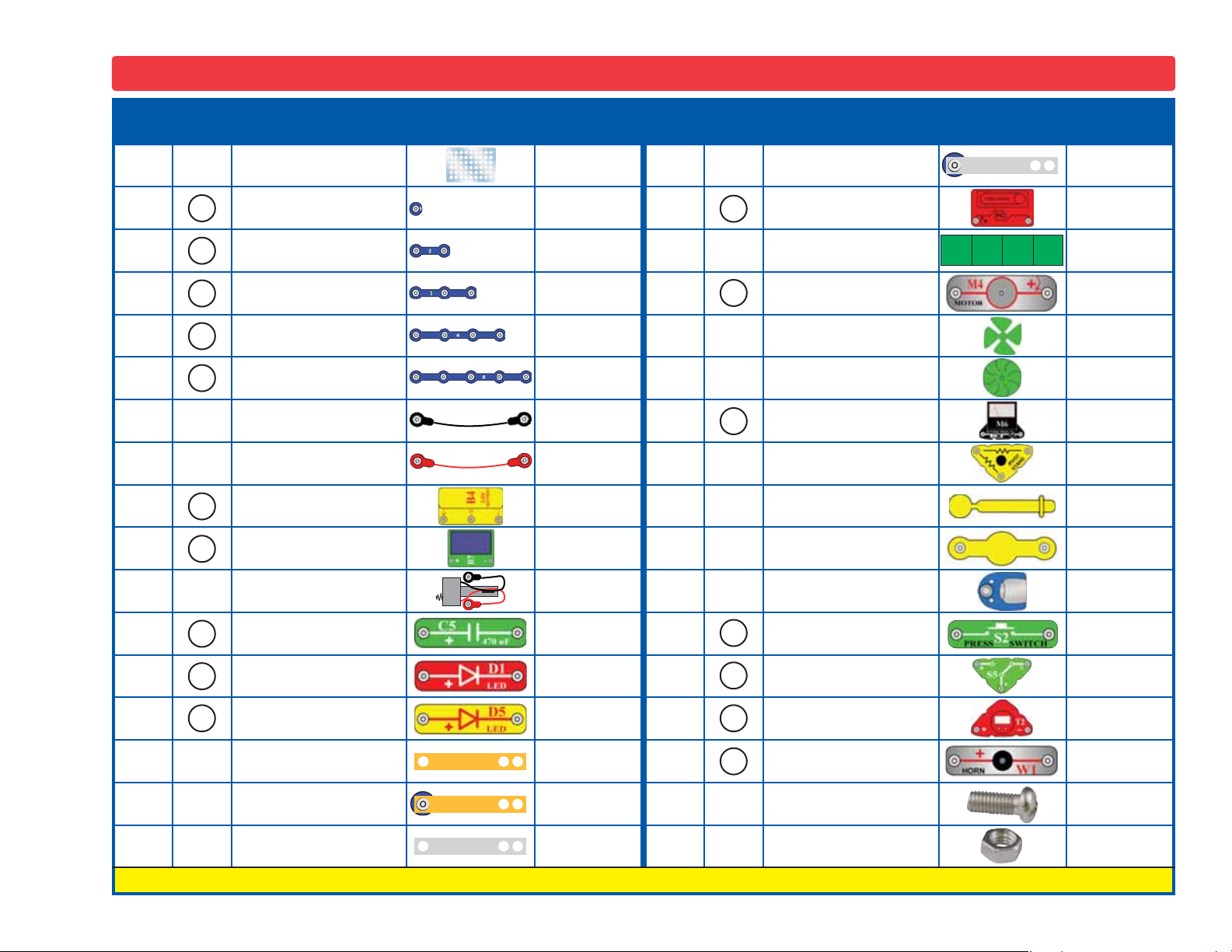
Parts List (Colors and styles may vary) Symbols and Numbers
Qty. ID Name Symbol Part # Qty. ID Name Symbol Part #
1
Base Grid
(11.0” x 7.7”)
6SCBG
1
Zinc Electrode with
Snap
6SCEZS
2
3
3
1
1
1
1
1
1
1
1
1
2
3
4
5
B4
B7
C5
1-Snap Wire 6SC01
2-Snap Wire 6SC02
3-Snap Wire 6SC03
4-Snap Wire 6SC04
5-Snap Wire 6SC05
Jumper Wire (Black) 6SCJ1
Jumper Wire (Red) 6SCJ2
Rechargeable Battery
Solar Cell 6SCB7
Battery Eliminator for
FM Radio
470μF Capacitor 6SCC5
6SCB4
6SCBE
1
1
1
1
1
1
1
1
1
1
1
HC
M4
M6
S2
Hand Crank 6SCHC
Liquid Holder 6SCLH
Motor 6SCM4
Wind Fan 6SCM4B
Water Wheel 6SCM4C
Meter 6SCM6
Pivot Stand Base 6SCPSB
Pivot Post 6SCPSP
Pivot Top 6SCPST
FM Radio 6SCFM2
Press Switch 6SCS2
1
1
3
1
3
D1
D5
Red LED 6SCD1
Yellow LED 6SCD5
Copper Electrode 6SCEC
Copper Electrode
with Snap
Zinc Electrode 6SCEZ
6SCECS
1
1
1
3
3
S5
T2
W1
Slide Switch 6SCS5
Clock 6SCT2
Horn 6SCW1
Screw 8-32 Phillips 641840
Nut 8-32 644800
You may order additional / replacement parts at our website: www.snapcircuits.net
-2-
Page 4
How to Use It
Snap Circuits®uses building blocks
with snaps to build the different
electrical and electronic circuits in the
projects. Each block has a function:
there are switch blocks, light blocks,
battery blocks, different length wire
blocks, etc. These blocks are different
colors and have numbers on them so
that you can easily identify them. The
circuit you will build is shown in color
and numbers, identifying the blocks
that you will use and snap together to
form a circuit.
For Example:
This is the switch block which is green
and has the marking on it. The part
symbols in this booklet may not exactly
match the appearance of the actual
parts, but will clearly identify them.
S2
There is also a 1-snap wire that is used
as a spacer or for interconnection
between different layers.
A large clear plastic base grid is
included with this kit to help keep the
circuit blocks properly spaced. You will
see evenly spaced posts that the
different blocks snap into. The base
has rows labeled A-G and columns
labeled 1-10.
Next to each part in every circuit
drawing is a small number in black. This
tells you which level the component is
placed at. Place all parts on level 1 first,
then all of the parts on level 2, then all
of the parts on level 3, etc.
Some circuits use the jumper wires to
make unusual connections. Just clip
them to the metal snaps or as
indicated.
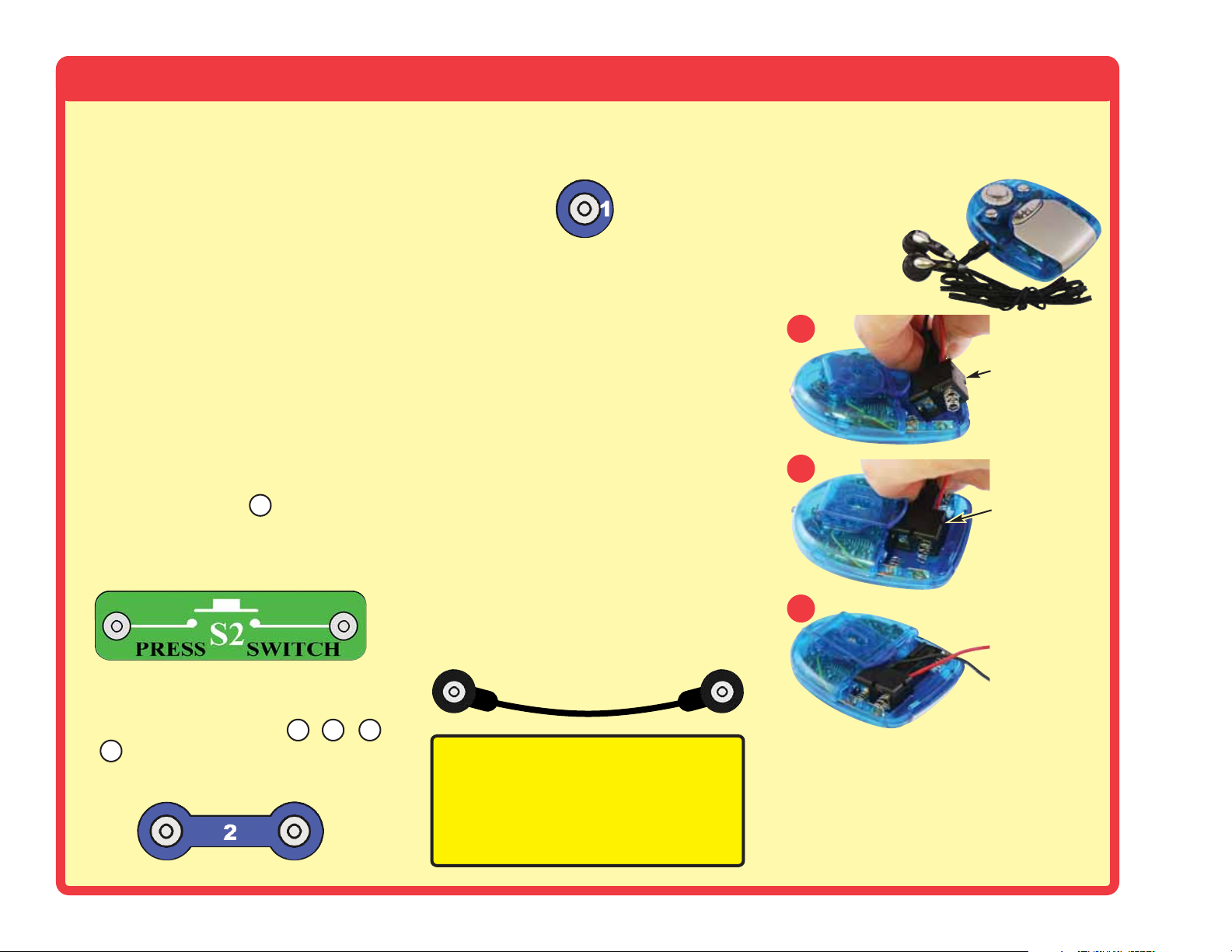
To use the radio, connect the earphone
and battery eliminator to it as shown.
Connect the wires from the battery
eliminator to a circuit
as shown in the
projects.
Connect
earphone
1
Insert eliminator
2
Press eliminator
down into slot
3
Slide eliminator
into position
This is a wire block which is blue and
comes in different wire lengths.
This one has the number , , ,
5
or on it depending on the length of
2
3
the wire connection required.
-3-
4
Note: While building the projects, be
careful not to accidentally make a direct
connection across the battery holder (a
“short circuit”), as this may damage
and/or quickly drain the batteries.
Alternately, the radio may be operated
independently of this product using two
“AAA” batteries (not included). Be sure
to install batteries with the (+) and (–)
terminals as shown in the battery
compartment.
Page 5
How to Use It
The 3.6V rechargeable battery (B4)
may have discharged during
shipping and distribution. Recharge
it as shown in project 3 and others.
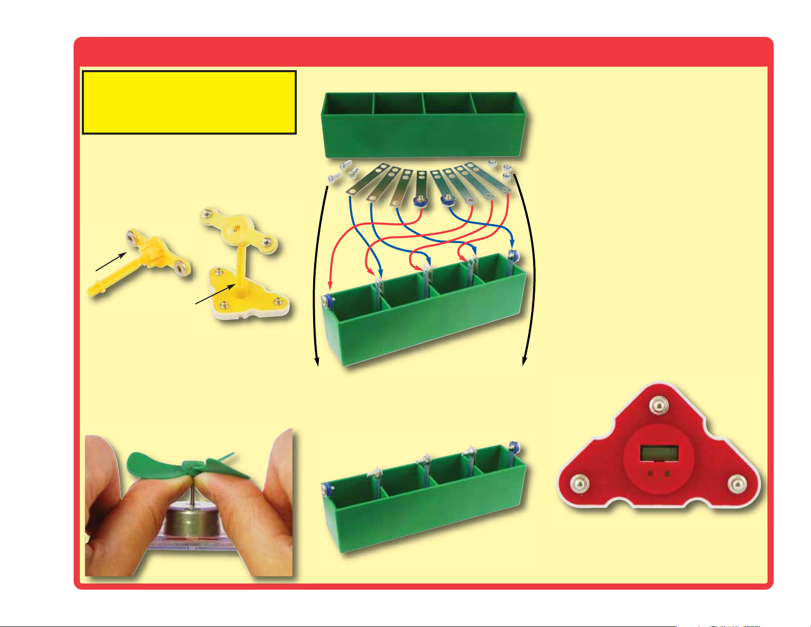
Sometimes parts will be mounted on a
pivot, so they can be adjusted for the
best angle to the wind or sun.
Assemble the pivot as shown here:
Insert post into pivot top,
snapping into place.
Insert the other end of the
post into pivot base.
Whenever the motor (M4) is used, it
will have the wind fan or the water
wheel placed on top; simply push the
fan onto the shaft. To remove it, push
up on it with a screwdriver or your
thumbs, being careful not to break it.
Assembling the Liquid Power Source:
Connect the 3 electrode parts together
with screws and nuts as shown.
Tighten by hand, a screwdriver is not
needed.
If the copper and zinc electrodes get
corroded through use, use sandpaper,
steel wool, or a scraper to remove the
corrosion and improve performance.
Setting the time on the clock (T2):
• Press the left button to select what to
change (month, date, hour, or
minutes).
• Press the right button until it is
correct.
• Press the left button until the time is
showing, then press the right button
once to start.
• The colon (“:”) will be flashing when
the clock is running.
• Press the right button to display the
date.
-4-
Page 6
About Your Snap Circuits
®
Green Parts
(Part designs are subject to change without
notice).
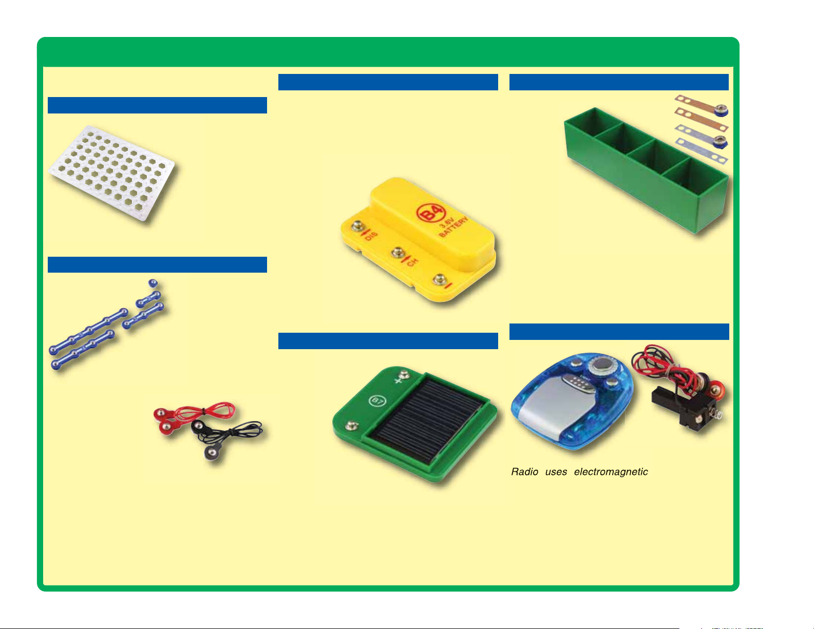
BASE GRID
The base grid is a platform for
mounting parts and wires.
It functions like the
printed circuit
boards used in
most electronic
products, or like how
the walls are used for
mounting the electrical
wiring in your home.
SNAP WIRES & JUMPER WIRES
The blue snap wires
are wires used to
connect components.
They are used to
transport electricity and do
not affect circuit performance.
They come in different lengths to
allow orderly arrangement of connections
on the base grid.
The red and black
jumper wires make
flexible connections for
times when using the snap wires
would be difficult. They also are
used to make connections off the base grid (like
the projects using water).
Wires transport electricity just like pipes are used
to transport water. The colorful plastic coating
protects them and prevents electricity from
getting in or out.
BATTERY
The battery (B4) contains a rechargeable
battery and some supporting parts. This battery
produces an electrical
chemical reaction. This “voltage” can be thought
of as electrical pressure, pushing electricity
through a circuit just like a
pump pushes water
through pipes.
This voltage is
much lower
and much
safer than
that used in
your house
wiring. Using more
batteries increases the
“pressure” and so more
electricity flows.
voltage using a reversible
Battery (B4)
SOLAR CELL
The solar cell (B7)
contains positively
and negatively
charged
silicon
crystals,
arranged
in layers
that cancel
each other out.
When sunlight shines on it,
charged particles in the light
unbalance the silicon layers and produce an
electrical voltage of up to 7V. The maximum
current depends on the type of light and its
brightness, but will be much less than a battery
can produce. Bright sunlight works best, but
incandescent light bulbs also work.
Solar Cell (B7)
LIQUID HOLDER & ELECTRODES
Electrodes
Liquid
Holder
Most sodas
and fruit juices are
lightly acidic. The acid
is similar to the material
used in some types of batteries
but not nearly as strong. The acid will
react with the copper and zinc electrodes to
make an electric current, like a battery. Each of
the four compartments in the liquid holder
produces about 0.7V, but the current is very low
and may not last long.
RADIO & BATTERY ELIMINATOR
Radio & Battery Eliminator
Radio uses electromagnetic waves to send
information through the air. Snap Circuits
includes a standard FM radio, and a battery
eliminator to use with it. The radio can also be
used with two 1.5V “AAA” type batteries (not
included). The battery eliminator has circuitry to
protect the radio from the higher voltages, which
you can produce with this kit, since these could
damage the radio.
®
-5-
Page 7
About Your Snap Circuits
®
Green Parts
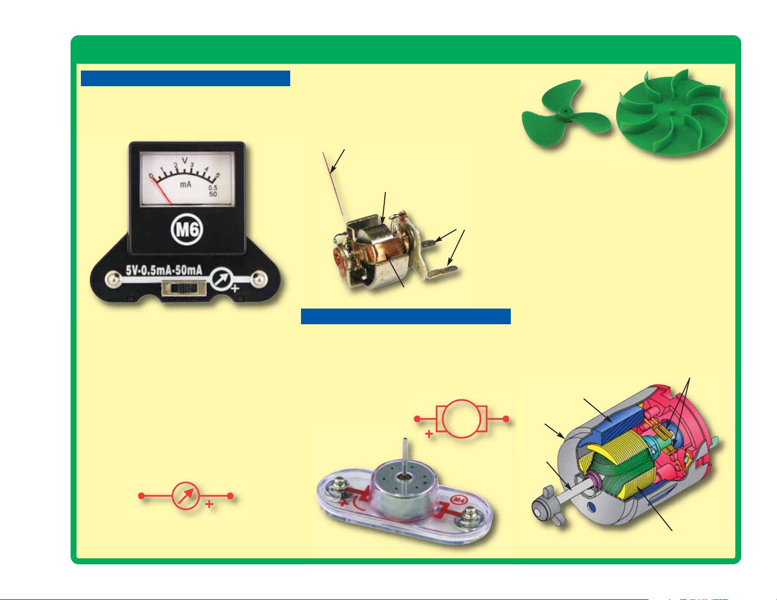
METER
The meter (M6) is an important measuring
device. You will use it to measure the voltage
(electrical pressure) and
electricity is flowing) in a circuit.
Meter (M6)
The meter measures voltage when connected in
parallel to a circuit and measures the current
when connected in series in a circuit.
This meter has one voltage scale (5V) and two
current scales (0.5mA and 50mA). These use the
same meter but with internal components that
scale the measurement into the desired range.
Sometimes resistors in the pivot stand will be
used to change the 5V scale to 10V, or the 0.5mA
scale to 5mA.
current (how fast
Inside the meter there is a fixed magnet and a
moveable coil around it. As current flows through
the coil, it creates a magnetic field. The
interaction of the two magnetic fields causes the
coil (connected to the pointer) to move (deflect).
Pointer
Magnet
Contacts
Coil
MOTOR
The motor (M4) converts electricity into
mechanical motion. An electric current through
the motor will turn the shaft.
It can also be used as a generator, since it
produces an electric current when the shaft is
turned.
Motor Symbol
Fan
How does electricity turn the shaft in the motor?
The answer is magnetism. Electricity is closely
related to magnetism, and an electric current
flowing in a wire has a magnetic field similar to
that of a very, very tiny magnet. Inside the motor
is a coil of wire with many loops. If a large electric
current flows through the loops, the magnetic
effects become concentrated enough to move
the coil. The motor has a magnet inside, so as
the electricity moves the coil to align it with the
permanent magnet, the shaft spins.
When used as a generator, wind or water turns
the shaft. A coil of wire is on the shaft, and as it
spins past the permanent magnet an electric
current is created in the wire.
Magnet
Shell
Shaft
Water Wheel
Power Contacts
Meter Symbol
Motor (M4)
Electromagnet
-6-
Page 8
About Your Snap Circuits
μ
®
Green Parts
The hand crank (HC) is a motor with a
gearbox attached. The gearbox
spins the motor shaft faster
but with less force
than you are
turning the
hand crank.
Hand Crank
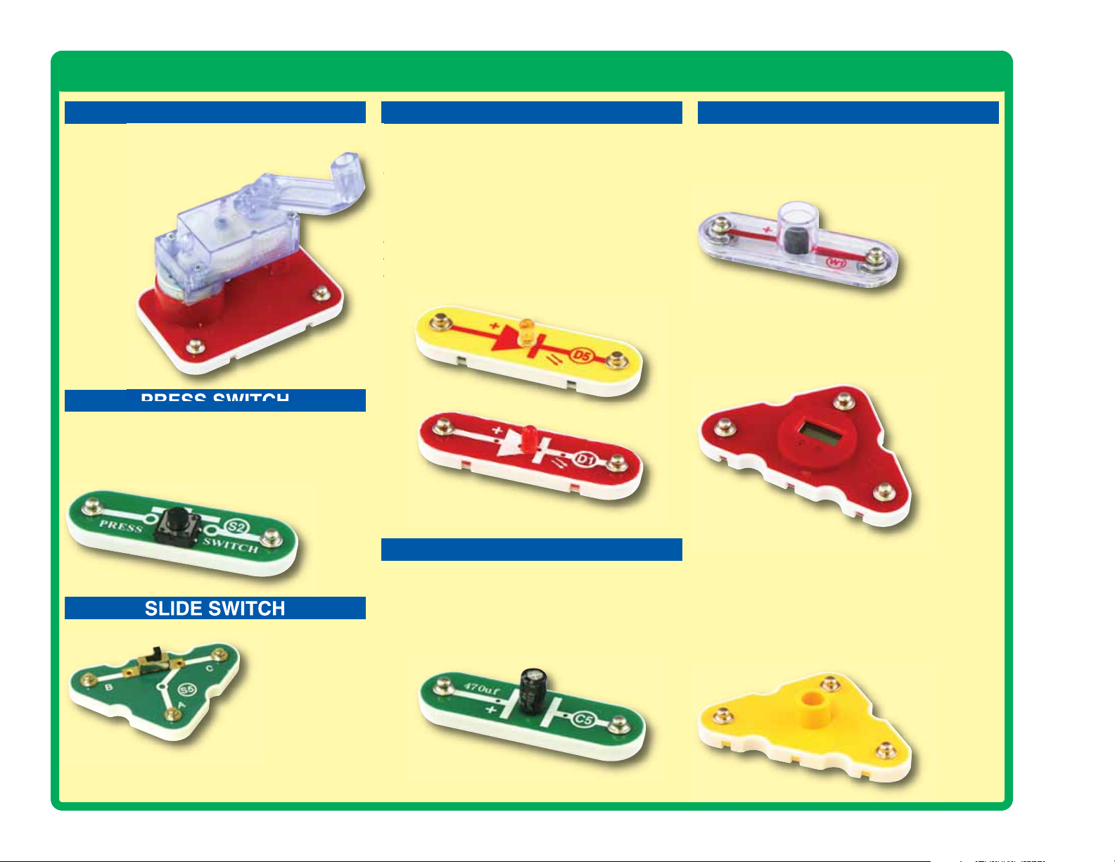
PRESS SWITCH
The press switch (S2) connects (pressed, “ON”)
or disconnects (not pressed, “OFF”) the wires in
a circuit. When ON it has no effect on circuit
performance. It turns on electricity just like a
faucet turns on water
from a pipe.
RED & YELLOW LEDsHAND CRANK
The red & yellow LED’s (D1 & D5) are light
emitting diodes, and may be thought of as a
special one-way light bulb. In the “forward”
direction, (indicated by the “arrow” in the symbol)
electricity flows if the voltage exceeds a turn-on
threshold (about 1.5V for red and 2V for yellow);
brightness then increases. A high current will
burn out the LED, so the current must be limited
by other components in the circuit. LED’s block
electricity in the “reverse” direction.
LED’s (D1) & (D5)
OTHER PARTS
The horn (W1) converts electricity into sound by
making mechanical vibrations. These vibrations
create variations in air pressure, which travel
across the room. You “hear”
sound when your ears feel
these air pressure
variations.
Horn (W1)
The clock (T2) contains a small crystal. When a
crystal is struck by an electronic pulse, it vibrates.
A microelectronic circuit makes the pulse and
measures the vibration rate. The vibration rate is
used as a time
standard, from
which minutes,
hours, and the
date are
calculated.
Clock (T2)
Press Switch (S2)
SLIDE SWITCH
Slide Switch (S5)
no effect on circuit
performance. It directs electricity just like a value
controls water in a pipe.
-7-
The slide switch
(S5) connects
(ON) the center
snap to one of the
other two snaps.
When connected it has
CAPACITOR
μ
The 470
pressure (voltage) for periods of time. This
storage ability allows it to block stable voltage
signals and pass changing ones. Capacitors are
used for filtering and delay circuits.
F capacitor (C5) can store electrical
Capacitor (C5)
The pivot stand contains two resistors, 47Ω and
10KΩ. Resistors “resist” the flow of electricity and
are used to control or limit the electricity in a
circuit. Materials like metal have very low
resistance (<1Ω), while materials like paper,
plastic, and air have near-infinite resistance.
Increasing circuit
resistance reduces
the flow of
electricity.
Pivot Stand
Page 9

DO’s and DON’Ts of Building Circuits
After building the circuits given in this booklet, you may wish to experiment
on your own. Use the projects in this booklet as a guide, as many
important design concepts are introduced throughout them. Every circuit
will include a power source (the batteries), a resistance (which might be
a lamp, motor, electromagnet, etc.), and wiring paths between them and
back.
You must be careful not to create “short circuits” (very low-resistance
paths across the batteries, see examples below) as this will damage
components and/or quickly drain your batteries. Elenco®Electronics is
not responsible for parts damaged due to incorrect wiring.
Here are some important guidelines:
ALWAYS use eye protection when experimenting on your own.
ALWAYS include at least one component that will limit the current
through a circuit, such as an LED, clock, or horn.
ALWAYS use the switches in conjunction with other components that
will limit the current through them. Failure to do so will create
a short circuit and/or damage those parts.
ALWAYS disconnect your batteries immediately and check your wiring
if something appears to be getting hot.
ALWAYS check your wiring before turning on a circuit.
NEVER connect to an electrical outlet in your home in any way.
NEVER touch the motor when it is spinning at high speed.
For all of the projects given in this book, the parts may be arranged in
different ways without changing the circuit. For example, the order of
parts connected in series or in parallel does not matter — what matters
is how combinations of these sub-circuits are arranged together.
Examples of SHORT CIRCUITS - NEVER DO THESE!!!
Placing a 3-snap wire directly across a
power source is a SHORT CIRCUIT.
!
NEVER
DO!
This is also a SHORT CIRCUIT.
NEVER
When the switch (S2) is
!
NEVER
DO!
You are encouraged to tell us about new circuits you create. If they are
unique, we will post them with your name and state on our website at
www.snapcircuits.net/kidkreations.htm. Send your suggestions to
Elenco
®
Electronics: elenco@elenco.com.
turned on, this large circuit
has a SHORT CIRCUIT
path (as shown by the
arrows). The short circuit
prevents any other portions
of the circuit from ever
working.
!
DO!
Warning to Snap Circuits®owners: Use only parts
included in this kit to prevent damage. Our website
www.snapcircuits.net has approved circuits that you
can use.
Elenco®provides a circuit designer so that you can make your own
Snap Circuits®drawings. This Microsoft®Word document can be
downloaded from www.snapcircuits.net/SnapDesigner.doc or
through the www.snapcircuits.net web site.
WARNING: SHOCK HAZARD - Never connect your Snap
Circuits®set to the electrical outlets in your home in any way!
-8-
Page 10
Advanced Troubleshooting
Red & black jumper wires: Set the meter
2.
Elenco®Electronics is not responsible for
parts damaged due to incorrect wiring.
If you suspect you have damaged parts,
you can follow this procedure to
systematically determine which ones need
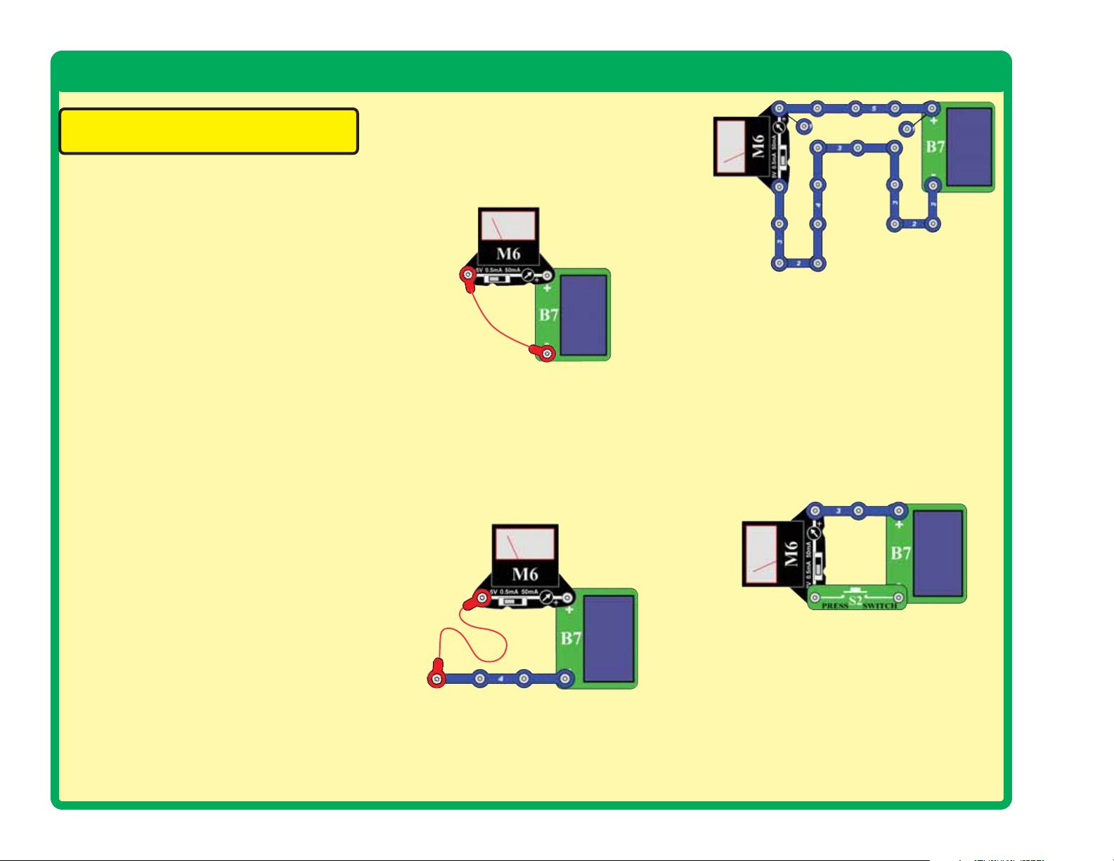
replacing:
1. Hand crank (HC), solar cell (B7), and
meter (M6):
the solar cell and set it to the 5V setting.
Place the solar cell in sunlight or near a
bright light source (incandescent light bulbs
are best); the meter pointer should move.
Then place the meter directly across the
hand crank and turn the crank handle
clockwise; the meter pointer should move for
all the meter switch settings (5V, 0.5mA, and
50mA).
•
If the 5V meter setting works with the hand
crank but not the solar cell, then the solar
cell is damaged. Be sure you used a bright
light source and removed any protective
plastic wrap covering the solar cell.
• If the 5V meter setting works with the
solar cell but not the hand crank, then the
hand crank is damaged.
• If the 5V meter setting does not work with
either the solar cell or the hand crank,
then the meter is damaged.
• If the 5V meter setting works with the
hand crank but the 0.5mA or 50mA meter
settings do not, then the meter is
damaged.
Place the meter directly across
to the 5V setting and use this circuit to test
each jumper wire. Place the solar cell (B7)
near the same light source you used in step
1. The jumper wire is damaged if the meter
pointer does not move.
Snap wires: Set the meter to the 5V setting
3.
and use this circuit to test each snap wire,
one at a time. Place the solar cell (B7) near
the same light source you used in step 1.
The snap wire is damaged if the meter
pointer does not move.
(Adult supervision recommended)
If you prefer, you can test all the snap wires
at once using this circuit. If the meter pointer
does not move, then test the snap wires one
at a time to find the damaged one.
Press switch (S2): Set the meter to the 5V
4.
setting and build this circuit. Place the solar
cell (B7) near the same light source you
used in step 1. If the meter pointer does not
move when you press the switch, the switch
is damaged.
5.
Red and yellow LEDs (D1 & D5): Place
each LED directly across the hand crank
(HC), without snapping it on. Make sure the
“+” side of the LED matches the “+” side of
the hand crank. Turn the crank handle
clockwise; the LED will light unless it is
damaged.
-9-
Page 11
Advanced Troubleshooting
μ
(continued)
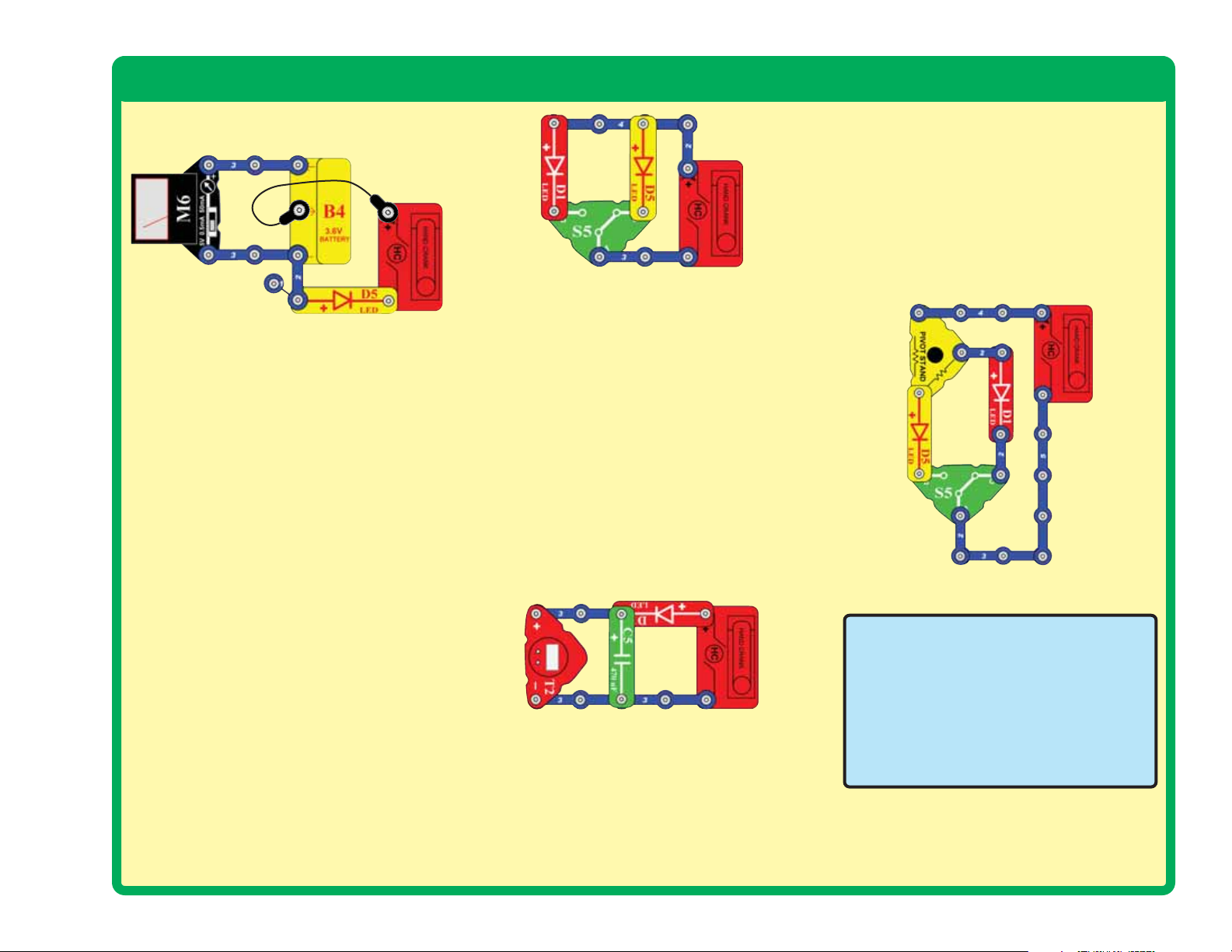
6. Battery (B4): Build the circuit shown here
and set the meter (M6) to the 5V setting.
• The meter will measure more than 3V if
the battery is charged up.
• If the meter pointer does not move from
zero then either the battery is completely
discharged or it is damaged.
• Turn the hand crank (HC) clockwise and
check that the yellow LED (D5) comes on
when you crank fast (indicating that the
crank is charging the battery).
• If the meter was measuring zero then
turn the crank for at least 20 seconds
with the yellow LED on to see if it can be
recharged.
• If the battery cannot be recharged, then
it is damaged.
• If the battery needs to be recharged, you
can use this circuit or see project 3 for
other charging circuits.
7.
Slide switch (S5): Slide switch (S5): Build
this circuit and turn the hand crank (HC)
clockwise until an LED lights. The red LED
(D1) should light when the switch is in
position B, and the yellow LED should light
when the switch is in position C; otherwise
the slide switch is damaged.
μ
Clock (T2), 470
8.
(W1), and motor (M4):
shown below, but remove the 470μF
capacitor. Turn the hand crank (HC)
clockwise and the clock display should turn
on.
Add the 470μF capacitor back in; the clock
display should stay on for a while after
you stop turning the crank; otherwise the
capacitor is damaged.
• Replace the clock with the horn. Turning
the crank should sound the horn.
• Replace the horn with the motor (“+” on
top, the fan doesn’t matter). Turning the
crank clockwise should spin the motor
shaft clockwise.
9.
Radio and battery eliminator: Build project
118. Turning the hand crank (HC) should
operate the radio. The radio can be tested
without the battery eliminator using two
“AAA” type 1.5V batteries (not included).
F capacitor (C5), horn
Build the circuit
Pivot stand resistors: The pivot stand
10.
base has resistors mounted inside; they
can be tested using this circuit. Turn the
hand crank (HC) clockwise to light the
LEDs. If the slide switch (S5) is in position
B then the yellow LED (D5) will be bright.
If the slide switch is in position C, the red
LED (D1) will be dim. If either LED does
not light or the red one is brighter than the
yellow then the pivot stand is damaged.
11. Check the remaining parts by inspecting
them for damage.
Elenco®Electronics, Inc.
150 Carpenter Avenue
Wheeling, IL 60090 U.S.A.
Phone: (847) 541-3800
Fax: (847) 520-0085
e-mail: help@elenco.com
Website: www.elenco.com
You may order additional /
replacement parts at:
www.snapcircuits.net
-10-
Page 12

Project Listings
Project #
1 Crank Charger 13
2 Hand Cranking 13
3 Best Charging Circuits 14
4 Solar Power 15
5 Solar Motor 15
6 Solar Charger 16
7 Solar Charger 5mA 16
8 Windmill 17
9 Windy Lights 17
10 Multi Power 18
11 Battery Power 18
12 Wind Warning 19
13 Light Charger 19
14 Electric Circuit 20
15 Close the Door 21
16 Feeling Switchy 21
17 Voltage & Current 22
18 Light Emitting Diode 22
19 Resistors 23
20 Honk Your Horn 23
21 Clock 24
22 Capacitor 24
23 Motor 25
Description Page #
Project #
24 Water Wheel 25
25 Motor Voltage 25
26 Crank Motor 26
27 Crank Motor Voltage 26
28 Radio Current 27
29 Long Light 28
30 LED Currents 28
31 Battery Load 29
32 Battery Load Current 29
33 Make Your Own Parts 30
34 Liquid Resistors 30
35 Liquid Light 30
36 Moving Voltage 31
37 Moving More Voltage 31
38 Power Sources 32
39 Powering Clock 33
40 Powering Horn 33
41 Powering LED 33
42 Powering Big Voltage 33
43 Powering Big Current 33
44 Splitting Current 34
45 Splitting Current
Description Page #
Differently 34
Project #
46 Splitting Different
47 Voltage Order 35
48 Current Order 36
49 Sources in Series 37
50 Sources in Parallel 37
51 Two in Series 38
52 Two in Parallel 38
53 Sound Starter 39
54 Two Speed Motor 39
55 Big Blade Wind Horn 40
56 Windy Time 40
57 Wind Charger
58 Wind Charger
59 Kick Start Motor 41
60 Short Wind Power 42
61 Wind Horn 42
62 Liquid Battery 43
63 Juice Battery 43
64 Cola Light 44
65 Yellow Cola 44
66 Electricity From Water 45
Description Page #
Currents 34
with Light 41
with Horn 41
-11-
Page 13

Project Listings
Project #
67 Water Light 45
68 Cola Clock 46
69
70 Changing Water
71 FM Radio 47
72 Hydro Lights 48
73
74 Using Stored Water 49
75 Water Redirection 49
76 One of the Most
77
78 Harnessing Static
79
80 Big Thrust 52
81 Solar Light Clock 53
82 Solar Light Charger 53
83 Solar Lights Row 54
84 Crank Support 54
85 Crank Charging 55
Description Page #
Cola Clock with Memory
Pressure to
Electrical Pressure 47
Directional Wind Lights
Powerful Forces
in the Universe 50
Electricity Against Water
Electricity 51
Storing Energy in Water
46
48
50
52
Project #
86 Crank Sound 55
87 Hand Lights 56
88 Hand Noise 56
89 Heavy Fan 57
90 Remote Heater 57
91 Remote Water Heater 58
92 Electrical Material
93 Morse Code 59
94 Morse Light 59
95 Everything Circuit 60
96 Light Signal for Radio 61
97 Light & Sound
98 Speed Indicator 62
99 Sound Pulse 62
100 Motor Speed LED 63
101 Energy Converter 63
102 Energy Conversion 64
103
104 Mechanical Energy
105 Triple Current Meter 65
106 Clock with Memory 65
Description Page #
Checker 58
Signal for Radio 61
Small Energy Conversion
Conversion 64
64
Project #
107 Capacitor Charging 66
108 Stopped Motor Alarm 66
109 Saving Energy 67
110
111 Regulating Power 68
112 Sun & Wind Light 68
113 Hybrid 69
114 Hybrid Car Concept 69
115 LED or Bulb? 70
116 Water Timer 70
117 Solar Fan 71
118 Hand Radio 71
119 Hand Charger 72
120 Parallel Cranking 72
121 Hard to Crank 73
122 Slow In Flash Out 73
123 Filling Station 74
124 Gas Pedal 74
125 Volt Meter 75
126 Anemometer 75
127 Current Meter 76
128 Wind Direction 76
129 Windy Radio 77
Description Page #
Energy Transmission Loss
67
-12-
Page 14
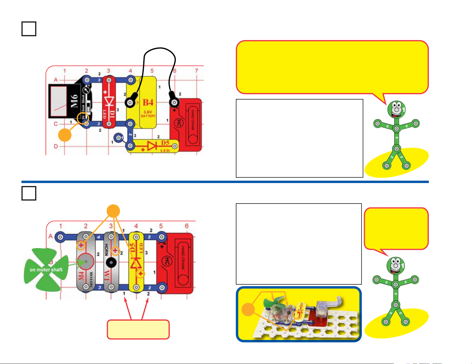
Project #1 Crank Charger
Although the battery is rated as 3.6V, it may charge to as high as 4.0V. If you
are monitoring the voltage using the meter, you may see the voltage quickly
reach 3.6V, but this does not mean that the battery is fully charged. When
the battery is discharging to power something, the voltage is nearly steady
for a long while then drops off quickly. The same thing occurs when it is
charging. Recharging the battery will quickly reach around 3.6V but it needs
much more charging to avoid a quick drop-off when discharging.
Build the circuit shown here and set the meter
(M6) to the 5V setting. The meter will measure
about 3.6V if the battery is charged up.
5V
Project #2
+
Turn the hand crank (HC) clockwise. The
yellow LED (D5) comes on when you crank
fast, indicating that the crank is charging the
battery.
If the battery needs to be recharged, you can
use this circuit to charge it.
Hand Cranking
Build the circuit shown by placing all the parts with
a black 1 next to them on the clear plastic base grid
first. Then, assemble parts marked with a 2, and
finally the parts marked with a 3. Be sure to place
the parts with their (+) side oriented as shown.
Place the wind fan on the motor (M4) shaft. Turn the
handle on the hand crank (HC) in both directions to
make things happen.
Warning: the hand crank is sturdy but not
indestructible. If you push hard on it or crank it really
fast you may break it.
The hand crank uses
magnetism to change
the mechanical energy
of the spinning shaft
into electricity.
-13-
+
Placement Level
Numbers
Page 15

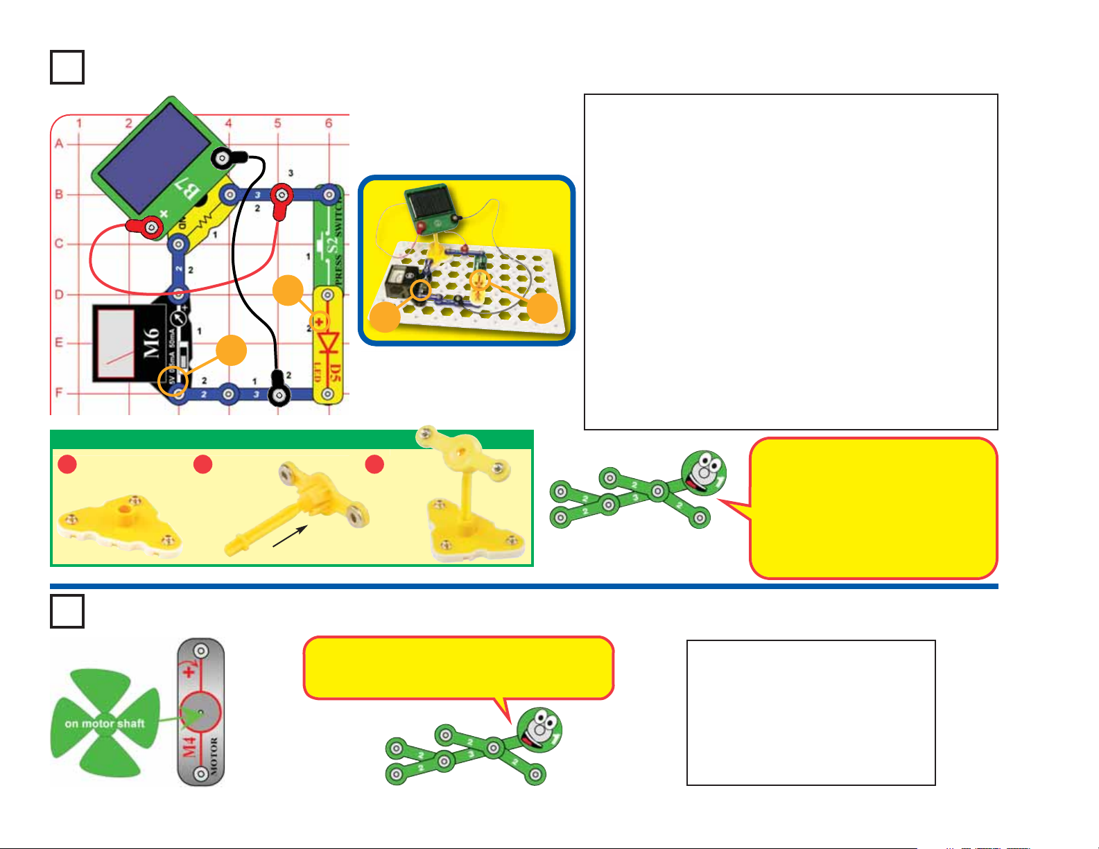
Project #3 Best Charging Circuits
Your rechargeable battery (B4) will need to be recharged often; use
any of these circuits. Place the solar cell in sunlight or about 12
inches from an incandescent light bulb of 60W or more. It takes a
few hours to charge the battery. Fluorescent lights do not work well
with solar cells. You can’t hurt the battery by overcharging.
Circuit #1: The solar cell is on the pivot so you can adjust it for best
angle to your light source, and uses the meter (M6) to measure the
voltage.
Circuit #2: The solar cell is on the pivot so you can adjust it for best
angle to your light source.
Circuit #3: This uses only a few parts, so you can build many of the
other circuits while charging the battery.
Best angle adjustment to light
1 2 3
source with voltage measurement:
Best angle adjustment to light source: Minimum parts:
Although the battery is rated as 3.6V, it may
charge to as high as 4.0V. If you are monitoring
the voltage using the meter, you may see the
voltage quickly reach 3.6V, but this does not
mean that the battery is fully charged. When the
battery is discharging to power something, the
voltage is nearly steady for a long while then
drops off quickly. The same thing occurs when it
is charging. Recharging the battery will quickly
reach around 3.6V but it needs much more
charging to avoid a quick drop-off when
discharging. Recharge the battery for several
hours.
5V
ASSEMBLING PIVOT STAND
Place base on
1 2 3
flat level surface.
Snap ball
on pivot
post into
pivot top.
Insert post
into base.
-14-
Page 16
Project #4
+
5V
ASSEMBLING PIVOT STAND
Place base on
1 2 3
flat level surface.
Snap ball
on pivot
post into
pivot top.
5V
Insert post
into base.
+
Solar Power
Assemble the pivot, mount the solar cell (B7) on it, and place it in the
circuit as shown. Place all the parts with a black 1 next to them on the
clear plastic base grid first, then parts marked with a 2, and finally the
parts marked with a 3.
Connect the solar cell to the circuit using the red and black jumper wires.
Place the circuit so the solar cell is in bright sunlight or close to an
incandescent light bulb. Set the meter (M6) to the 5V setting.
The meter is measuring the voltage produced by the solar cell. Adjust
the position of the position of the solar cell on the pivot to see how the
voltage produced changes depending on the angle to the light source
and the brightness.
Position the solar cell to make the highest voltage you can. Now push the
press switch to run the yellow LED (D5) with the solar cell. Notice how the
voltage produced drops when the LED is connected.
Note: The voltage produced is actually twice that shown on the meter
(so a 3V reading is really 6V), because a resistor in the pivot stand is
changing the scale.
Part B: Replace the yellow LED with the red LED (D1) and press the
switch. See how much it affects the solar cell voltage.
Your solar cell makes electricity from
sunlight, but only a small amount. In
bright sunlight it produces a voltage
of about 7V, but this is reduced when
lots of current is flowing. That is why
the voltage drops when you connect
the yellow LED.
-15-
Project #5 Solar Motor
The motor needs less electricity from the solar
cell as it speeds up, so the solar cell voltage is
higher as the motor gets faster.
In the preceding circuit, replace the
yellow LED (D5) with the motor (M4, in
either direction) and place the wind fan
on it. Now press the switch and watch
how the voltage changes as the solar
cell runs the fan. Depending on your
light source, the fan may need a push
to get started or may not work at all.
Page 17
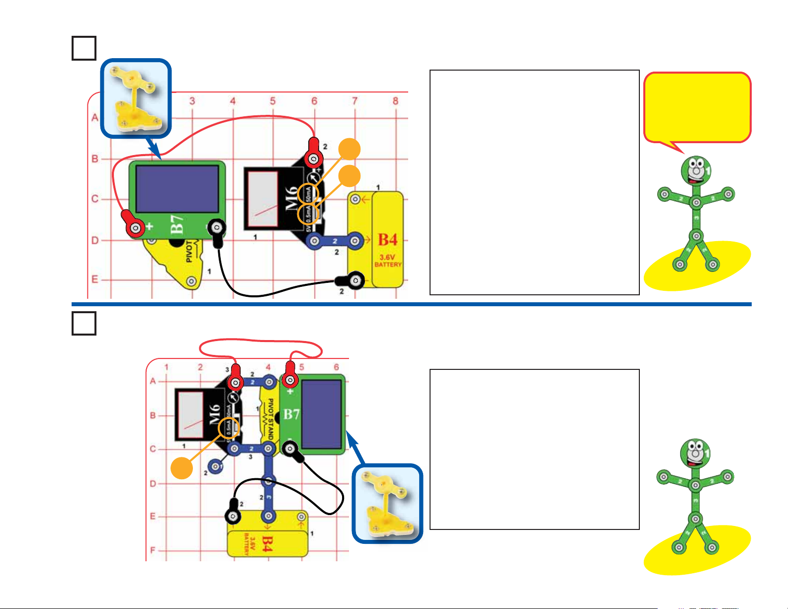
Project #6
Solar Charger
Project #7
50mA
0.5mA
Assemble the pivot, mount the solar cell (B7) on
it, and place it in the circuit as shown. Connect the
solar cell to the circuit using the red and black
jumper wires. Place the circuit so the solar cell is
in bright sunlight or near an incandescent light
bulb. Set the meter (M6) to the 0.5mA or 50mA
setting.
The solar cell is charging the battery and the meter
is measuring the current. The current depends on
the type and brightness of your light source, and
how much your battery needs recharging. Adjust
the position of the solar cell to make the highest
current; in bright sunlight it will be around 10mA.
When placed in sunlight or about 12 inches from a
60W incandescent light bulb, the solar cell will
typically recharge the battery in a few hours.
Current will flow into the battery even when it is
fully charged. You can’t hurt the battery by
overcharging with the power sources in this kit.
Solar energy is free,
abundant, and causes no
pollution. However it is
difficult to harvest it
because even low power
solar cells are expensive.
Solar Charger 5mA
0.5mA
Modify the preceding circuit to match this one.
Set the meter (M6) to the 0.5mA setting. Place
the solar in sunlight or near an incandescent
light bulb. The solar cell is charging the battery
and the meter is measuring the current.
This circuit uses a resistor in the pivot stand to
change the 0.5mA scale on the meter to a 5
mA scale, so read the current on the 0-5
scale. Charging current is usually in this
range. Place your hand above the solar cell to
see how easily the current changes, and try
different light sources.
-16-
Page 18
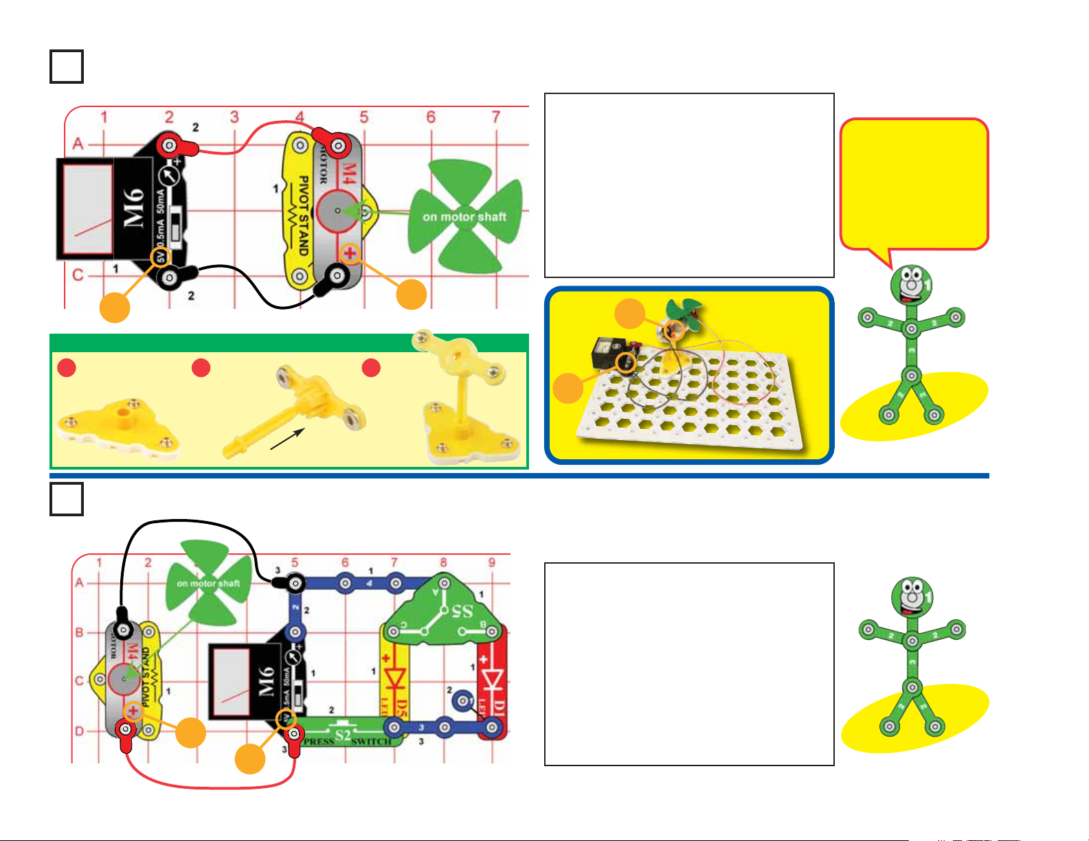
Project #8 Windmill
Assemble the pivot, mount the wind fan on the motor
(M4), mount the motor on the pivot, place the pivot
on the base grid and connect it to the meter (M6)
using the red and black jumper wires. Set the meter
to the 5V setting.
Blow on the fan or place it in a strong wind (either
outside or near an electric fan). You may need to give
the fan a push to get it started. The meter measures
how much voltage your “windmill” produces. Adjust
the pivot position to see how the voltage produced
changes with the angle to the wind.
The windmill uses
magnetism to change the
mechanical energy of the
spinning shaft into
electricity. The voltage it
produces is usually lower
than the solar cell, but the
current is higher.
5V
ASSEMBLING PIVOT STAND
Place base on
1 2 3
flat level surface.
Snap ball
on pivot
post into
pivot top.
Project #9
+
5V
+
Insert post
into base.
+
5V
Windy Lights
Build the circuit shown. Set the meter to the 5V
setting. Blow on the fan or place it in a strong wind
(either outside or near an electric fan). The meter
measures how much voltage your “windmill”
produces. You may need to give the fan a push to get
it started.
Push the press switch (S2) to connect one of the
LEDs (D1 & D5) to the windmill. The voltage
produced drops a little, but not as much as for the
solar cell circuits. Flip the slide switch (S5) to try the
other LED. Compare the brightness of the LEDs at
different wind speeds.
-17-
Page 19
Project #10 Multi Power
Build the circuit shown. Set the
+
5V
meter to the 5V setting. The
meter measures the voltage
produced by the windmill, solar
cell, and hand crank, which are
connected to work together.
You can change the meter setting
to 50mA, to measure the current
produced.
Project #11 Battery Power
The red and yellow
LEDs (D1 & D5) are
used here to keep the
different power sources
from interfering with
each other, by
controlling the direction
electricity flows.
+
Make sure the battery is charged up (see projects 1-3).
Build the circuit with the motor and fan on the pivot stand,
and connect the jumper wires as shown. Set the slide
switch (S5) to position B to turn on the circuit. The battery
runs the clock display (T2), horn (W1), red LED (D1), and
windmill (M4). Push the press switch (S2) and the hand
crank (HC) will also spin.
Part B: Set the slide switch to position C to disconnect
the battery, and blow on the fan or place it in a strong
wind. See if your “windmill” will run things as well as the
battery, and for how long.
Part C: Leave the slide switch at position C and push the
press switch while turning the hand crank to see how well
it runs things. Try cranking it in both directions.
See projects 1 & 3
if you need to
recharge the
battery (B4).
+
The battery can store
lots of energy, so it
can run lots of things
for a while. It is
available whenever
you need it, at the flip
of a switch.
-18-
Page 20
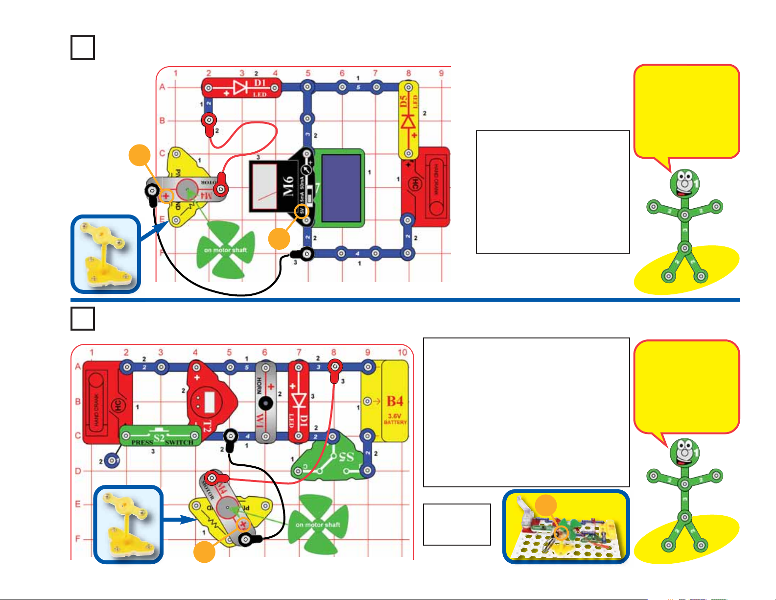
Project #12 Wind Warning
Build the circuit as shown, with the motor on
the pivot. Blow on the fan or place it in a strong
+
wind. Depending on the wind direction and the
setting of the slide switch (S5), you may see
lights or hear sound. You may need to give the
fan a push to get it started.
This circuit can be used to warn you of
dangerous winds.
+
Light ChargerProject #13
-19-
This circuit uses the solar cell (B7) to charge
the rechargeable battery (B4). Place the solar
cell in sunlight or near an incandescent light
bulb. The red LED (D1) lights when the battery
is being charged. The brighter the LED, the
faster it is charging.
Page 21
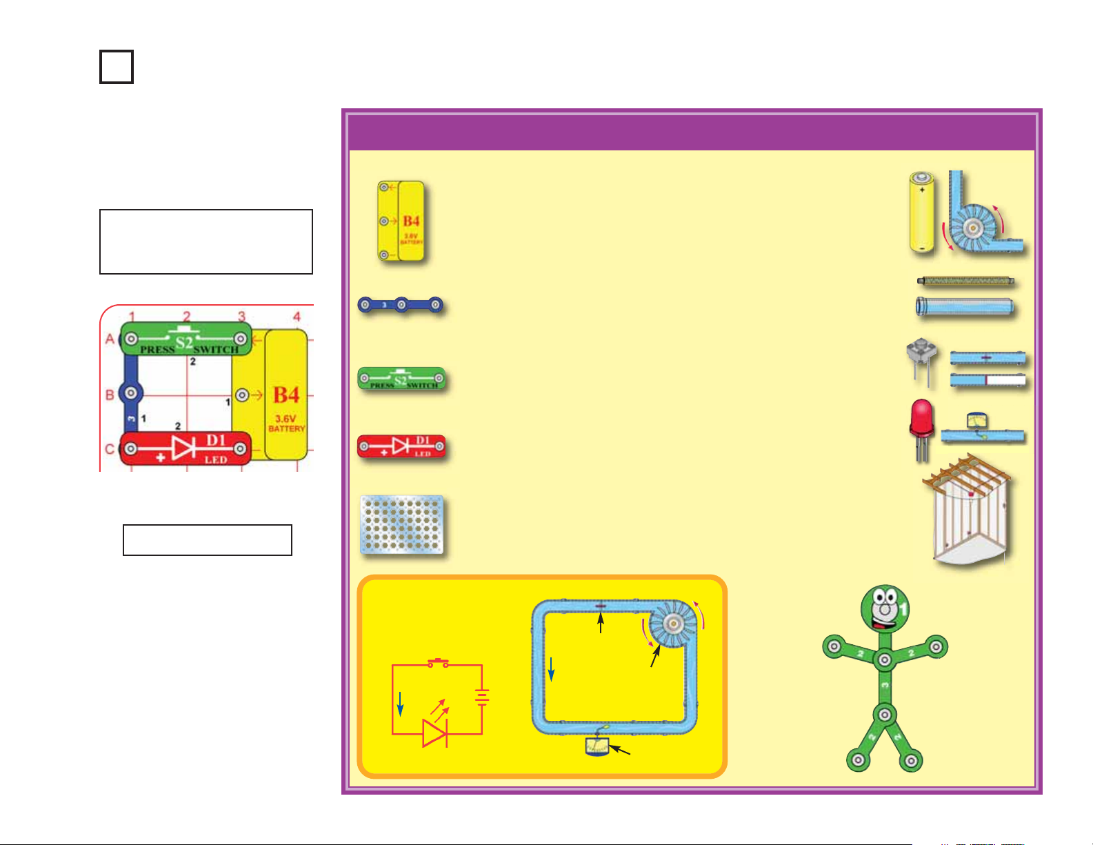
Project #14 Electric Circuit
Build the circuit shown and push
the press switch (S2) to turn on
red LED (D1).
Educational Corner:
What is really happening here?
1.The battery (B4, containing a 3.6V rechargeable battery with protection
circuitry) converts chemical energy into electrical energy and “pushes” it
through the circuit, just like the electricity from your power company. A
battery pushes electricity through a circuit just like a pump pushes water
through a pipe.
2.The snap wires (the blue pieces) carry the electricity around the circuit,
just like wires carry electricity around your home. Wires carry electricity
just like pipes carry water.
3.The press switch (S2) controls the electricity by turning it on or off, just
like a light switch on the wall of your home. A switch controls electricity
like a faucet controls water.
4.The red LED (D1, a “light emitting diode”) converts electrical energy into
light; it is similar to lights in your home. An LED shows how much
electricity is flowing in a circuit like a water meter shows how fast water
flows in a pipe.
See projects 1 & 3 if you need to
recharge the battery (B4).
5.The base grid is a platform for mounting the circuit, just like how wires are
mounted in the walls of your home to control the lights.
Comparing Electric
Flow to Water Flow:
Electric Paths
Switch
Battery
LED
Valve
Pump
Water Meter
-20-
Page 22
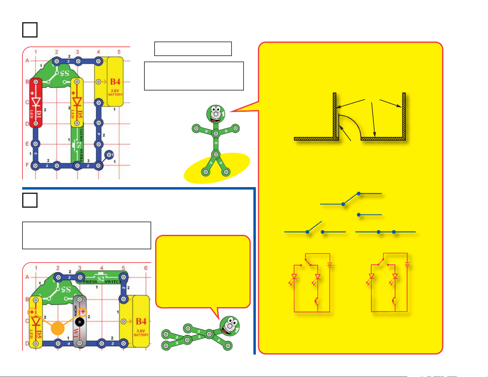
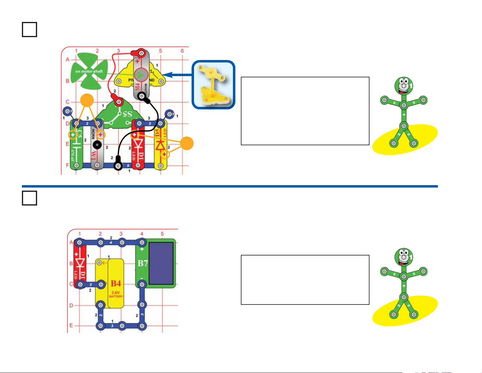
Project #15 Close the Door
Project #16
See projects 1 & 3 if you need to
recharge the battery (B4).
Build the circuit shown. The slide
and press switches (S5 & S2)
control the lights.
Feeling
The “on” position of a switch is also called the “closed”
position. Similarly, the “off” position is also called the
“open” position. This is because the symbol for a slide
switch is similar to the symbol for a door in an architect’s
drawing of a room:
Walls
Door
The electronics symbol for a slide switch should be
thought of as a door to a circuit, which swings open when
the switch is off. The “door” to the circuit is closed when
the switch is on. This is shown here:
Your S5 switch has 2 positions,
so it has a different symbol:
Build the circuit shown and push the press
switch (S2) to turn on light or sound. Switches
can be arranged in many different ways.
+
-21-
Switchy
The press switch allows
electricity to flow from the battery
to the circuit, and the slide switch
(S5) directs the electricity to
either the yellow LED (D5) or the
horn (W1). These switches are
like many switches in your home,
controlling lights and many other
things.
Open Switch (turned off) Closed Switch (turned on)
Left Switch Position Open
Right Switch Position Closed
(turned off)
(turned on),
right LED controlled by press
switch
Left Switch Position
Closed (turned on)
Right Switch Position
Open (turned off)
Page 23
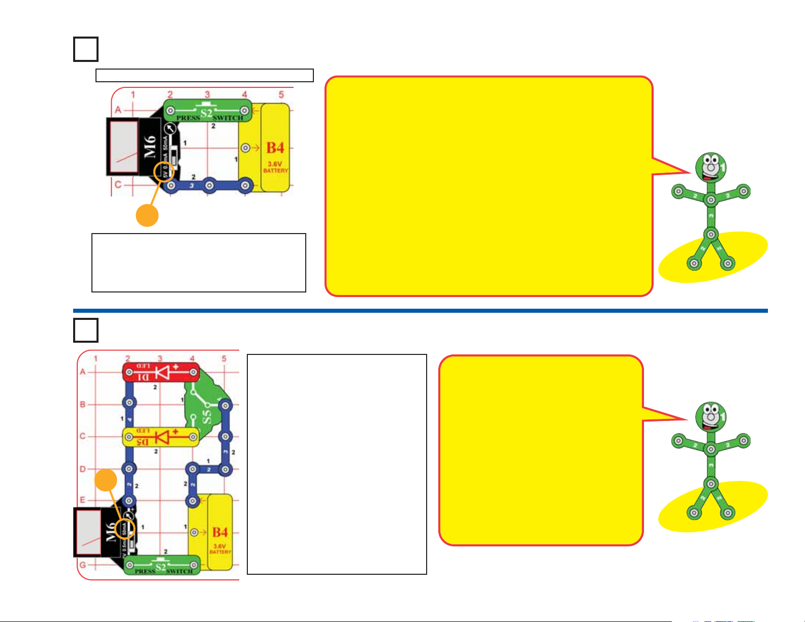
Project #17 Voltage & Current
See projects 1 & 3 if you need to recharge the battery (B4).
5V
Build the circuit shown. Set the meter (M6) to
the 5V setting. Push the switch (S2) to
connect the meter to the battery and measure
its voltage.
Electricity is the movement of subatomic charged particles (called
electrons) through a material due
to electrical pressure across the
material, such as from a battery.
The electrical pressure exerted by
a battery or other power source is
called voltage and is measured in
volts (V). Notice the “+” and “–”
signs on the battery. These
indicate which direction the battery
will “pump” the electricity.
Circuits need the right voltage to
work properly. For example, if the
voltage to a light bulb is too low
then the bulb won’t turn on; if too
Light Emitting DiodeProject #18
high then the bulb will overheat
and burn out.
The electric current is a measure
of how fast electricity is flowing in a
wire, just as the water current
describes how fast water is flowing
in a pipe. It is expressed in
amperes (A) or milliamps (mA,
1/1000 of an ampere).
The “power” of electricity is a
measure of how fast energy is
moving through a wire. It is a
combination of the voltage and
current (Power = Voltage x Current).
It is expressed in watts (W).
50mA
Build the circuit shown. Set the meter
(M6) to the 50mA setting.
For each of the slide switch (S5)
positions, push the press switch (S2)
to measure the current through one of
the LEDs (D1 & D5). Then change the
slide switch (S5) to measure the
current with the other LED, and
compare them.
Now set the meter to the 5V setting,
and compare the voltage measured
with each LED. The voltage for both
should be lower than what you
measured directly at the battery in the
preceding project, due to the voltage
needed to turn on the LEDs.
Light emitting diodes (LEDs) are one-way
lights with a turn-on voltage threshold. If the
voltage is high enough, they will light. The
yellow LED (D5) requires a higher voltage
to turn it on, but can get brighter.
When electric current flows through an
LED, energy is released as light; the color
depends on the material. LEDs are much
more energy efficient and last longer than
ordinary light bulbs but were only used in
low-power applications due to power limits,
cost, and limited colors. However, LEDs are
rapidly being improved and are increasingly
being used in home lighting.
-22-
Page 24
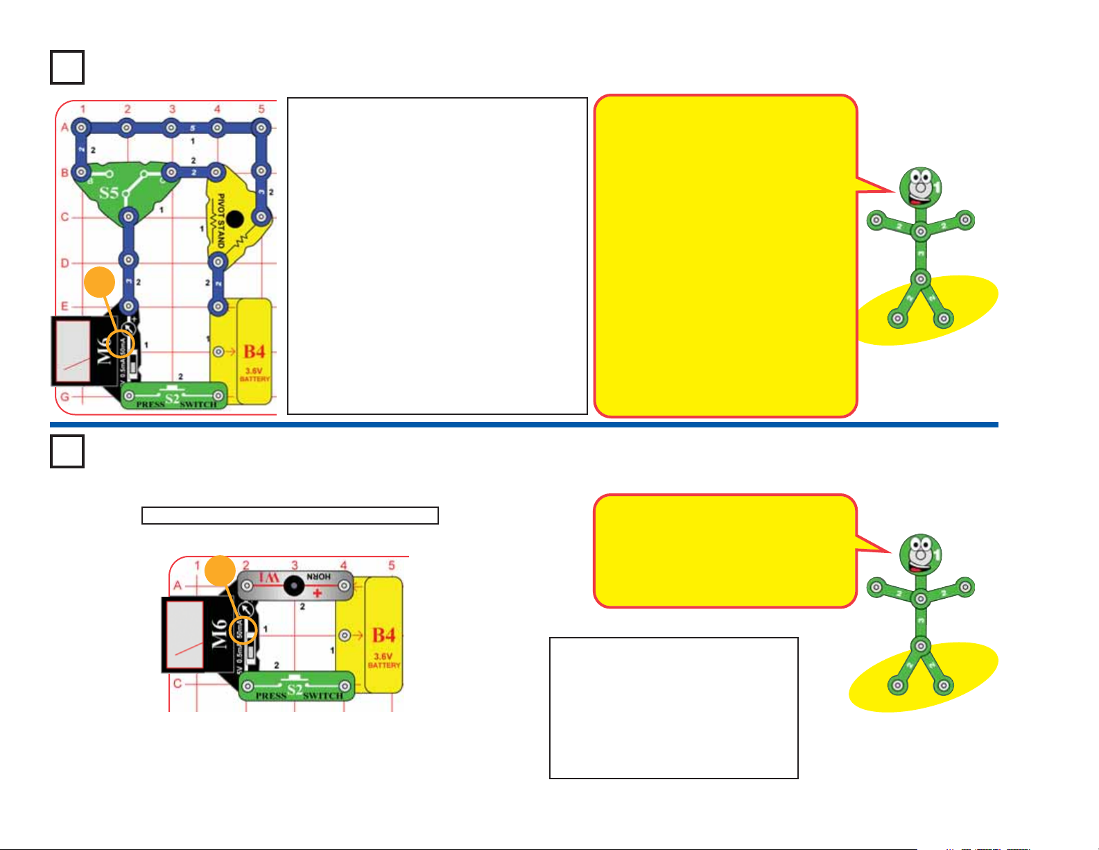
Project #19 Resistors
50mA
Build the circuit shown. Set the meter (M6) to the 50mA
setting and the slide switch (S5) to position C. The pivot
stand base has 47Ω and 10KΩ resistors in it. They are
used to control the flow of electricity in a circuit.
Push the press switch (S2) to measure the current
through the 47Ω resistor; it should be around 50mA.
To measure the current through the 10KΩ resistor,
set the meter to the 0.5mA setting and the slide
switch to position B. Push the press switch to show
the current, it should be around 0.4mA. The current
is much lower this time, because the 10KΩ is a higher
value resistor.
The meter has internal resistors, which scale the
measurement it makes into the ranges indicated on it.
The 10KΩ resistor can be used with it to double the
voltage scale to 10V. Keep the slide switch in position
B, set the meter to the 5V setting, and push the press
switch to measure the battery voltage using a 10V
scale (double what you read on the 5V scale).
See projects 1 & 3 if you need to recharge the battery (B4).
50mA
The resistance of a circuit represents
how much it resists the electrical
pressure (voltage) and limits the flow of
electric current. The relationship is
Voltage = Current x Resistance. When
there is more resistance, less current will
flow unless you increase the voltage.
Resistance is measured in ohms (Ω), or
kilo ohms (KΩ, 1000 ohms).
What is Resistance? Take your hands
and rub them together very fast. Your
hands should feel warm. The friction
between your hands converts your effort
into heat. Resistance is the electrical
friction between an electric current and
the material it is flowing through; it is the
loss of energy from electrons as they
move through the material.
Honk Your HornProject #20
The horn converts electricity into sound
energy by making mechanical vibrations.
These vibrations create variations in air
pressure, which travel across the room.
You “hear” sound when your ears feel
these air pressure variations.
-23-
Build the circuit, set the meter (M6) to
the 50mA setting. Push the switch (S2)
to “honk” the horn (W1), while the
meter measures the current through it.
Compare the current with the horn to
the current using the LEDs and
resistors in projects 18 and 19.
Page 25

Project #21 Clock
See projects 1 & 3 if you need to recharge the battery (B4).
0.5mA
The clock uses a liquid crystal display (LCD) to
show the time. LCDs use very little power, but
cannot be viewed in darkness. The electronic
circuitry that keeps time, controls the display, and
allows you to set the current time is complex but
has been miniaturized in an integrated circuit (IC).
Build the circuit shown. Set the meter (M6)
to the 0.5mA setting. The clock display will
light, but the meter will not measure any
current. See page 4 if you would like to set
the time.
The clock needs only about 0.005mA of
current to operate, and this is too small to
measure on your meter. The battery can
run the clock for a long time without being
recharged.
CapacitorProject #22
Capacitors store electricity in an electric field between metal plates, with a
small separation between them. This electric field is similar to the magnetic
field of a magnet. Compared to batteries (which store energy as separated
chemicals), capacitors can only store small amounts of energy, but they
can release it quickly, can be made in very small sizes, and are inexpensive.
0.5mA
Build the circuit shown. Set the meter (M6) to the 0.5mA
setting. Flip the slide switch (S5) back and forth to charge
and discharge the 470μF capacitor (C5).
With the switch in position C, a electricity briefly flows
from the battery into the capacitor to charge it up, as
shown by the meter. With the switch in position B, the
energy in the capacitor discharges through the red LED
(D1), which flashes.
The meter only measures current in one direction, but
you can flip it around to measure the discharge current.
-24-
Page 26

Project #23
50mA
How does electricity turn the shaft in the motor? The answer is
magnetism. Electricity is closely related to magnetism, and an
electric current flowing in a wire has a magnetic field similar to
that of a very, very tiny magnet. Inside the motor is a coil of wire
with many loops. If a large electric current flows through the loops,
the magnetic effects become concentrated enough to move the
coil. The motor has a magnet inside, so as the electricity moves
the coil to align it with the permanent magnet, the shaft spins.
Build the circuit shown. Set
the meter (M6) to the
50mA setting and place
the wind fan on the motor
(M4). Push the press
switch (S2) and watch the
current on the meter as the
motor speeds up.
Project #24Motor
Water Wheel
Remove the wind fan from the motor shaft and
replace it with the water wheel. Watch how the
current is different with the larger water wheel.
The water wheel is heavier, so it takes more
current to spin it, and doesn’t get as fast. Try laying
something on the water wheel to give it even more
weight.
See projects 1 & 3 if you need to
recharge the battery (B4).
Project #25 Motor Voltage
Do you know why the
current drops as the fan
speeds up?
Modify the preceding circuit into this one. Set the meter
(M6) to the 5V setting and place the wind fan on the motor
(M4). Push and release the press switch (S2) and watch
the voltage on the meter as the motor speeds up and
slows down.
Without pressing the switch, spin the fan clockwise with
your finger and watch the voltage. In the preceding
project, the current dropped as the fan sped up - now you
see why. The spinning fan produces a voltage in the
motor; this voltage opposes the voltage from the battery,
reducing the current as the motor speeds up.
How will the voltage and current change if you replace
the wind fan with the water wheel? Try it.
Electricity is generated
when you spin the motor
shaft. A coil of wire is on
the shaft, and as it spins
past the permanent
magnet an electric
current is created in the
wire.
-25-
5V
Page 27

Project #26 Crank Motor
See projects 1 & 3 if you need to recharge the battery (B4).
50mA
The hand crank is a motor with a gearbox attached.
The gearbox spins the crank handle slower but with
more force than when the motor shaft is spinning.
The slow-spinning crank handle may look boring
compared to the fast wind fan on the M4 motor, but
using a gearbox allows a low-power motor to move
heavier objects than they normally could.
Build the circuit shown. Set the meter
(M6) to the 50mA setting. Push the
press switch (S2) and watch the current
on the meter when the hand crank (HC)
spins. Compare the current with it to the
current when using the motor (M4) and
other parts.
Crank Motor VoltageProject #27
Modify the preceding circuit into this one. Set the
meter (M6) to the 5V setting. Set the slide switch (S5)
to position B and watch the voltage on the meter
when the hand crank spins.
Set the slide switch to position B to disconnect the
battery. Turn the crank handle counter-clockwise and
see how much voltage you generate. You can switch
the meter to the 50mA setting to see how much
current you produce when you spin the fan.
The motor in the hand
crank is different from the
M4 motor, but similar. Did
you see how much more
voltage and current you
can generate using the
hand crank than with the
M4 motor?
5V
Set the meter back to the 5V setting and the slide
switch back to position C. While it is spinning,
CAREFULLY AND WITHOUT USING MUCH
FORCE, try to turn the crank handle in both
directions. Feel how much easier or harder it is to turn
the crank when the battery voltage is helping or
opposing you. USING EXCESSIVE FORCE MAY
DAMAGE THE HAND CRANK!
-26-
Page 28

Project #28 Radio Current
INSTALLING BATTERY ELIMINATOR
1
Insert eliminator
under belt clip
2
Press eliminator
down into slot
50mA
See projects 1 & 3 if you
need to recharge the
battery (B4).
Install the battery eliminator connector into the battery compartment in the FM
radio, as shown. Build the circuit as shown, and connect the red and black snap
wires to it. Set the meter (M6) to the 50mA setting and the slide switch (S5) to
position B. Plug the earphones into the radio and place them earphones in your
ears. Turn the volume knob clockwise to turn on the radio, press the reset button,
then press the scan button several times to find a radio station (radio features
may vary).
Listen to the radio and notice how much current it needs. If the sound is distorted,
then recharge the battery using the solar cell or other power sources in this kit.
Use the volume knob to turn off the radio and look at the current measured on
the meter. Even though the radio is off, the current may not be zero. The battery
eliminator is using the remaining current. The radio needs only 3V and can be
damaged by higher voltages, so the battery eliminator has circuitry to reduce
the higher voltages from the power sources in this kit to 3V (for example, the B4
battery is 3.6V, the solar cell can produce 7V, and the hand crank can produce
more than 10V).
Your radio may have a light bulb or LED in it; if so, press the button to activate it.
It may only light dimly, but notice what happens to the current and sound.
Incandescent light bulbs need high current to get bright, much higher than LEDs.
The radio may not work when the light is activated, due to circuitry in the battery
eliminator, which protects the radio from overvoltage. The radio light will work if
you use the radio with normal “AAA” type batteries (not included).
The 470μF capacitor (C5) is used here to improve
50mA
sound quality by helping to stabilize the battery
voltage. The radio needs a steady voltage to produce
good sound quality, but the current it needs changes
slightly as the sound changes. The capacitor can only
supply a small amount of current but can react to
changes faster than the battery can. Remove the
capacitor from the circuit and see if you notice a
difference in sound quality.
3
-27-
Slide eliminator
into position
Volume-on/off knob
Reset
button
Earphone
plug
Scan
button
Note: Radio style and
features may vary.
Page 29

Project #29
See projects 1 & 3 if you need to recharge the battery (B4).
5V
Project #30 LED Currents
Long Light
Build the circuit and set the meter (M6) to the 5V setting. Set
the slide switch (S5) to position C and watch the voltage on
the meter for a while as the battery runs the yellow LED (D5).
How quickly does the voltage drop? Try placing the circuit in
darkness, changing the temperature, or varying the wind.
If your battery was recently recharged then you probably
found the voltage drops very, very slowly, and thought this
was boring. That was the idea - batteries can run things for
a long time and (unlike solar or wind power sources) are
hardly affected by changing weather conditions. Batteries
can provide power whenever you need it - but, eventually,
they do run out.
0.5mA
50mA
Build the circuit, set the slide switch (S5) to
position B, and set the meter (M6) to the 0.5mA
setting. This circuit has the LED in series with a
10KΩ resistor in the pivot stand. 10KΩ is a high
resistance, so the meter measures a small
current and the red LED (D1) is dimly lit. It is
easier to see the red LED if you take the circuit
into a dark room. If the LED does not light at all
then the battery needs to be recharged.
Switch the motor to the 50mA setting. Now set
the switch to position C, replacing the 10KΩ
resistor with a smaller 47Ω resistor in the pivot
stand. The LED is brighter now and the current is
higher.
Now push the press switch to bypass the 47Ω
resistor. The current and LED brightness are
even higher now.
Replace the red LED with the yellow LED (D5)
and see how the brightness and current change.
Adding resistors to a circuit is
like partially blocking a water
pipe, reducing the flow of water.
High currents can damage
LEDs, so resistors are usually
used with them to limit the
current. Your D1 and D5 LEDs
have internal resistors of
around 50Ω to protect them.
-28-
Page 30

Project #31 Battery Load
See projects 1 & 3 if you need to recharge the battery (B4).
The battery makes electricity using a chemical reaction, but has a limited amount
of chemicals and not all of it can react at the same time. When a battery cannot
supply as much current as a circuit needs, the voltage (electrical pressure)
drops. That is why the voltage drops when the switch connects the battery to
the rest of this circuit.
Engineers refer to all the devices a power source is running as the load, because
they are the burden the power source is carrying.
Build the circuit and set the meter (M6) to the 5V setting.
Set the slide switch (S5) to position C and read the
battery (B4) voltage when it is not running anything.
Now set the switch to position B and see what happens
to the voltage when everything turns on. If the battery is
5V
already weak, some modules may not start. If you watch
the voltage for a while, you will see it slowly drop as the
battery is discharged. If the battery was already weak,
the voltage will drop faster.
If you remove some of the devices the battery is running
(the LEDs, motor, and hand crank), then the voltage will
not drop as much when the switch is turned on.
Battery Load CurrentProject #32
-29-
50mA
Move the meter to the new location shown
and set the meter (M6) to the 50mA
setting. Set the slide switch (S5) to position
B and see how high the current is when the
battery is running all these devices.
You may see that the current is very high,
which explains why the battery voltage
dropped in the preceding project. Do you
know which devices need most of the
current? Remove some and see how the
current changes to see if you were right.
Your M6 meter is a
simple meter, don’t
expect it to be as
accurate as normal
electronic test instruments.
Page 31

Project #33 Make Your Own Parts
See projects 1 & 3 if you need to
recharge the battery (B4).
0.5mA
0.5mA
Method A (easy): Spread some water on the
table into puddles of different shapes, perhaps
like the ones shown here. Touch the jumper
wires to points at the ends of the puddles.
Method B (challenging): Use a SHARP pencil (No. 2 lead is best)
and draw shapes, such as the ones here. Draw them on a hard, flat
surface. Press hard and fill in several times until you have a thick,
even layer of pencil lead. Touch the jumper wires to points at the ends
of the drawings. You may get better electrical contact if you wet the
metal with a few drops of water. Wash your hands when finished.
Method C (adult supervision and permission required): Change
the setting on the meter to the 50mA scale. Use some double-sided
pencils if available, or VERY CAREFULLY break a pencil in half. Touch
the jumper wires to the black core of the pencil at both ends.
Liquid ResistorsProject #34
Build the circuit, set the meter (M6) to the 0.5mA setting,
and set the slide switch (S5) to position B. Add about 1/4 inch
of water to a cup or bowl. Connect the jumper wires to the
circuit as shown and place the loose ends in the water, make
sure the metal parts aren’t touching each other. Measure the
current through the water.
Add salt to the water and stir to dissolve it. The current
should be higher now, since salt water has less resistance
than plain water. If the current is too high to measure on the
0.5mA scale, switch to the 50mA scale.
Now add more water to the cup and watch the current.
If you have some distilled water, place the jumper wires in
it and measure the current. You should measure close to
zero current, since distilled (pure) water has very high
resistance. Normal water has impurities, which lower its
resistance. Now add salt to the distilled water and watch the
current increase as the salt dissolves!
You can also measure the current through other liquids.
Don’t drink any water or liquids used here.
Pure water has very
high resistance because
its electrons are tightly
held in place. Impurities
(such as dissolved dirt,
minerals, or salt)
decrease the resistance
because they have
loose electrons, which
disrupt the structure and
make it easier for other
electrons to move
through.
Resistance = Voltage / Current, so you can use the
battery voltage (3.6V) and the current you measure
to find the resistance of your puddles and drawings.
Long narrow shapes have more resistance than
short wide ones. The black core of pencils is
graphite, the same material used in the resistors in
the pivot stand.
Build the circuit, set the
meter (M6) to the 0.5mA
setting, and set the slide
switch (S5) to position B.
Make your parts using either
the water puddles method
(A), the drawn parts method
(B), or the pencil parts
method (C). Touch the metal
in the jumper wires to your
parts and read the current.
Project #35
Liquid Light
Replace the meter with the
red LED (D1, + on top).
Place the jumper wires back
into water, into salt water, or
on the shapes you drew.
-30-
Page 32

Moving VoltageProject #36
See projects 1 & 3 if you need to recharge the battery (B4).
Switches are
used to move
voltage around
a circuit.
5V
Build the circuit and set the meter (M6) to
the 5V setting. Place the wind fan on the
motor (M4). Set the slide switch (S5) to
position B. The red LED (D1) lights, the fan
spins, and the meter shows the voltage
across the motor. You may need to give the
fan a push to get it started. The voltage
produced by the battery is split between
the motor and the LED.
Push the press switch (S2). The LED turns
off, the motor speeds up, and the meter
shows a higher voltage across the motor.
With the press switch on, the full voltage
from the battery is available at the motor
because the LED is bypassed.
Project #37 Moving More Voltage
-31-
+
5V
Part B
Part C
The horn voltage plus the LED voltage should about equal the
battery voltage. It may be a little different, because the M6 meter
has limited accuracy. The voltage across the switch will be very
low when it is pressed.
Build the circuit and set the meter
(M6) to the 5V setting. Push the
switch (S2); the meter measures the
voltage across the horn (W1).
Part B: Move the meter so it is
across the red LED (D1). Push the
switch to measure the voltage
across the LED.
Part C: Move the meter so it is
directly across the battery (B4).
Push the switch to measure the
voltage produced by the battery.
Page 33

Power
Source
Battery
Hand
Crank
Project #38
Connect to
one source
at a time
Connect to
one source
at a time
Highest Meter
Voltage
Highest Meter
Current
Clock
(Project 39)
Horn
(Project 40)
Yellow LED
(Project 41)
Power Sources
Snap Circuits®Green has 6 electrical power sources: battery,
hand crank, solar cell, windmill, watermill, and liquid holder.
Let’s compare them. The watermill is similar to the windmill
and its messy, so we’ll skip it.
Connect the red & black jumper wires to the meter and to one
of the power sources at a time, as shown. Measure the voltage
produced using the 5V meter setting; then look at the current
produced using either the 0.5mA or the 50mA meter settings.
Some times the meter reading will be more than the 5V or
50mA scales. Take some notes in the table below.
A. Battery.
B. Hand Crank: Turn it clockwise at different speeds.
C. Solar cell: Place it in sunlight or near an incandescent lamp.
D. Windmill: Mount the motor on the pivot stand, place the
wind fan on it, and blow on it or place it in a strong wind. You
may need to give it a push to get it started.
E. Liquid energy source: Assemble it using the instructions on
page 4. Fill the compartments with cola or juice.
See projects 1 & 3 if
you need to recharge
the battery (B4).
Big Voltage
(Project 42)
Big Current
(Project 43)
The most powerful power
source is the one which
produces the best balance of
voltage and current. Different
types of circuits need different
levels of voltage and current.
For each power source, the
balance between voltage and
current produced can be
adjusted by changing its
construction or with how groups
of them are arranged.
Solar Cell
Windmill
Liquid
-32-
Page 34

Project #39
Project #40
Project #41
Powering Clock
Use the 5 power sources you
have set up in project 38 but
replace the meter with the clock
(T2) as shown. See if it works
with each power source (it
should). Take some notes in the
project 38 table - it has a column
for the clock.
You are not using the clock with
a separate energy storage
device, so notice how continuous
power is from each source (for
example, the clock stops when
you stop turning the hand crank).
Project #42
Powering
Big Voltage
Now replace the single LED with
the mini circuit shown here. See
which power sources light both
LEDs. Take some notes in the
project 38 table - it has a column
for Big Voltage.
This circuit needs the same
current as for the yellow LED by
itself. However, it needs higher
voltage to turn on both LEDs, one
after the other.
Powering Horn
+
Now replace the clock with the
horn (W1). See which power
sources it works with. Take some
notes in the project 38 table - it
has a column for the horn.
Project #43
Powering
Big Current
Now change to this mini circuit instead. Find out
which power sources can run both LEDs and
the horn. Take some notes in the project 38
table - it has a column for Big Current.
This circuit needs about the same voltage as
for the yellow LED by itself, but it needs higher
current to turn on both LEDs and the horn all at
the same time.
Powering LED
Now replace the horn with the
yellow LED (D5). See which
power sources it works with. Take
some notes in the project 38
table - it has a column for the
LED. You can replace the yellow
LED with the red LED (D1) and
compare it too if you like.
Each power source has advantages and
limitations:
A. Batteries have lots of power but they only
store energy, they don’t actually produce it.
B. The hand crank has lots of power but only
while you are turning the crank.
C. The solar cell has limited power, and only
while it has light.
D. The windmill makes good power but only in
a strong wind.
E. The liquid energy source has very little
power.
-33-
Page 35

Project #44
Splitting Current
B
+
50mA
C
Project #45
Part B
Part C
The current from the battery splits up between the horn and the LED. If
you add up the current you measured through the horn and LED (Parts
B & C), it should be the same as the current you measured from the
battery. (Your result may be a little different, because M6 is a simple
meter with low accuracy.)
Build the circuit and set the meter (M6) to the
50mA setting. Push the switch (S2); the meter
measures the current from the battery (B4).
Part B: swap the location of the meter with the
3-snap wire marked “B” (“+” side towards the
horn (W1)). Push the switch to measure the
current through the horn.
Part C: swap the “B” location of the meter with
the “C” 3-snap. Push the switch to measure
the current through the red LED (D1).
See projects 1 & 3 if you need to recharge the battery (B4).
Project #46
Splitting Current
Differently
Replace the horn or red LED
with the motor (M4, with wind
fan blade) or yellow LED (D5).
Try different combinations and
see how the current changes.
Splitting Different
Currents
Replace the battery (B4) with
the solar cell (B7). Try different
combinations and see how the
current changes.
-34-
Page 36

Project #47
Voltage Order
D
E
See projects 1 & 3 if you need to recharge the battery (B4).
C
B
A
5V
F
This circuit has the battery (B4) and solar cell producing voltage to
push electric current through the LEDs and motor. Although the
meter is set to the 5V scale, a resistor in the pivot stand changes
the voltage scale to 10V, so double the voltage you read on the
meter.
A. Connect the loose end of the red jumper wire to the snap
marked A to measure the voltage between there and the black
jumper wire’s location. It is just the voltage across the battery.
B. Move the end of the red jumper from point A to point B, to see
how much the voltage is increased by the solar cell.
C. Move the end of the red jumper from point B to point C, to see
how much the voltage changed across the switch.
D. Move the end of the red jumper from point C to point D, to see
how much the voltage was reduced as it pushed current through
the yellow LED.
E. Move the end of the red jumper from point D to point E, to see
how much the voltage was reduced as it pushed current through
the motor.
F. Finally, move the end of the red jumper from point E to point F,
to see how much the voltage was reduced as it pushed current
through the red LED.
Part 2: Take the end of the black jumper wire off the 5-snap wire.
Place the loose ends of the red and black jumper wires across any
two points in the circuit to measure the voltage change between
them (remember that the meter only measures positive voltages).
Build the circuit and place the wind fan on the motor (M4). Set the
meter (M6) to the 5V setting. Connect the black jumper wire between
the meter and 5-snap wire. Connect one end of the red jumper wire
to the pivot stand; leave the other end loose. Set the slide switch (S5)
to position B. Place the solar cell (B7) in bright sunlight or near an
incandescent lamp. If the light is bright enough, the LEDs (D1 & D5)
will light and the fan will spin. You may need to give the fan a push to
get it started.
-35-
Page 37

Project #48
50mA
Part B
Current Order
Build the circuit; it has the parts arranged in a loop. Place the wind fan
on the motor (M4). Set the meter (M6) to the 50mA setting. Set the slide
switch (S5) to position B. Place the solar cell (B7) in bright sunlight or
near an incandescent lamp. If the light is bright enough, the meter will
show a current, the LEDs (D1 & D5) will light, and the fan will spin. You
may need to give the fan a push to get it started. If the meter shows
zero, you can use the 0.5mA setting.
Part B: Rearrange the parts around the loop into the order shown, or
any similar order you like. Keep the “+” side of the parts in the same
direction as you move parts around the loop, and keep the light on the
solar cell the same as before. The LED brightness, fan speed, and
current shown on the meter should be the same no matter how you
order the parts.
This circuit has the battery (B4) and solar cell
producing voltage to push electric current through the
LEDs and motor. The current is flowing counterclockwise around the loop, and is the same through all
parts. If you rearrange the parts in the loop, without
changing their “+” orientation to the flow of current,
then you have exactly the same circuit.
See projects 1 & 3 if you need to recharge the battery (B4).
-36-
Page 38

Project #49 Sources in Series
5V
See projects 1 & 3 if you need to recharge the battery (B4).
Build the circuit shown. Place the solar cell
(B7) in sunlight or close to an incandescent
lamp. Set the meter to the 5V setting, but
double the reading it shows, since a resistor in
the pivot stand converts the scale to 10V.
Push the press switch (S2). If the slide switch
(S5) is set to position B, then the meter shows
the combined battery (B4) and solar cell (B7)
voltage. If it is set to position C, then the meter
shows only the solar cell voltage.
Vary the light on the solar cell and see how
the voltage changes.
The voltage produced
will be lower when these
sources are running
something that needs
lots of current, because
the solar cell can only
produce a small amount
of current.
Project #50 Sources in Parallel
-37-
Build the circuit shown. Place the solar cell
(B7) in sunlight or close to an incandescent
lamp. Set the meter to the 5V setting, but
double the reading it shows, since a resistor in
the pivot stand converts the scale to 10V. If the
slide switch (S5) is set to position B, then the
meter shows the battery (B4) voltage. If it is
set to position C, then the meter shows the
solar cell (B7) voltage.
If you push the press switch (S2), then the
battery and solar cell are connected in parallel
with each other, and the meter shows the
resulting voltage. Vary the light on the solar
cell and see how the total voltage changes.
5V
Page 39

Project #51
See projects 1 & 3 if you need to recharge the battery (B4).
Two in Series
+
Set the switch (S5) to position B, the red
LED (D1) lights and the horn (W1)
sounds. Current flows from the batteries
through the LED and horn back to the
battery through the switch.
The closed switch completes the circuit.
In electronics this is called a closed
circuit. When the switch is set to “C”, the
current can no longer flow back to the
battery, so the LED goes out and the
horn stops making noise. In electronics
this is called an open circuit.
Project #52 Two in Parallel
The lights in your home
+
When you close the switch, both the LED
and horn turn on. Current flows from the
batteries through the LED and horn back
to the battery through the switch.
are wired in parallel so if
one burns out, the others
stay on.
Remove the horn and notice that the LED
does not change in brightness. In a
parallel circuit, current has more than one
path so removing the horn does not
affect the LED. The voltage is the same
across the LED and horn, but not the
current.
-38-
Page 40

Project #53 Sound Starter
See projects 1 & 3 if you need to recharge the battery (B4).
+
Set the slide switch (S5) to position B. The
LEDs (D1 & D5) light but there is little or no
sound. Push the press switch (S2) to make
the sound work.
The voltage produced
will be lower when these
sources are running
something that needs
lots of current, because
the solar cell can only
produce a small amount
of current.
Project #54 Two Speed Motor
Set the slide switch (S5) to position B; the fan
spins and the red LED (D1) turns on,
indicating slow mode. The LED helps protect
the motor from getting the full voltage when
the slide switch is closed. Part of the voltage
goes across the LED and the rest goes
across the motor (M4).
-39-
Pushing the press switch (S2) bypasses the
red LED and now all the voltage is across the
motor, so it spins faster.
While the fan spins, carefully use you finger
to speed it up; the LED should turn off. As the
motor spins faster, its resistance increases
and voltage across it rises. Now there is not
enough voltage to light the LED until the
motor slows down again.
Page 41

Project #55 Big Blade Wind Horn
5V
+
+
Project #56
Place the water wheel on the motor (M4) and
mount the motor on the pivot. Connect the red
and black snap wires to the circuit as shown.
Set the meter (M6) to the 5V setting.
Hold the “water-windmill” in a strong, steady
wind (such as near an electric fan), and adjust
its position on the pivot to get the highest
voltage on the meter. If the wind is strong
enough, the horn will sound. Blocking the
wind on one side of the fan with your hand
may direct the air flow better and make the fan
work better.
+
Windy Time
The 470μF capacitor (C5) can store a small
amount of electricity. The clock needs very
little electricity to operate, so the capacitor can
run it for a while when the wind is not blowing.
The red LED is like a one-way light, only
allowing electricity to flow in one direction.
Here it is used to prevent electricity stored in
the capacitor from discharging through the
motor when the wind is not blowing.
The water wheel was
made to use with
water, but wind can
push it too.
5V
Build the circuit shown. Set the meter to the 5V setting. Blow
on the fan or place it in a strong wind (either outside or near
an electric fan). The meter measures how much voltage your
“windmill” produces. You may need to give the fan a push to
get it started.
+
The clock display (T2) should be on, and stay on for a while
when the wind is not blowing. Together the “windmill” and
capacitor can run the clock using free, clean wind power. The
red LED (D1) will not light.
If you would like to set the time on the clock, see page 4.
-40-
Page 42

Project #57 Wind Charger
Project #58
+
0.5mA
Build the circuit shown. Set the meter
(M6) to the 0.5mA setting. Blow hard
on the fan or place it in a very strong
wind (either outside or near an electric
fan).
with Light
A problem with using wind to power a light is
that the wind isn’t always blowing when you
need the light on. On the other hand, the
wind is often blowing when you don’t need
the light on. So here you use the battery to
store energy from the windmill when the wind
is blowing, and then run the yellow LED when
you need the light on. This way light is always
available from clean, free wind power.
The “windmill” charges the battery (B4)
when the wind is blowing hard, and the
meter measures the charging current.
Push the press switch (S2) to turn on
the yellow LED (D5).
Wind Charger
with Horn
Ice Storage units utilize a conventional air
conditioner to make ice at off hours using off-peak
electricity that is often sold at lower rates. The ice is
stored in a large, well-insulated tank. When there is
demand for air conditioning, refrigerant is circulated
through coils in the ice. The chilled refrigerant then
flows through the building's air-conditioning system
inside the home or business to provide cooling.
Replace the yellow
LED (D5) with the
horn (W1, “+” on
right”). The circuit
works the same
except pressing the
switch makes sound
from the horn.
Here the horn is run
using wind power, by
using the battery for
storage.
-41-
Project #59 Kick Start Motor
When this technique is used, they call the capacitor
Sometimes motors under a load are
difficult to get started. A capacitor can
be used to give the motor a little kick. In
this project setting the slide switch (S5)
to the right will charge the 470μF
capacitor (C5), then moving it to the left
will give the motor a little kick. Since no
other power is applied, the motor will not
go very far on the small amount of
power stored in the capacitor. This is still
a good way to get a motor started as
power is supplied.
a “Starting Capacitor”. A capacitor start motor is a
split-phase induction motor with a starting
capacitor inserted in series with the startup
winding, creating a much greater starting torque.
Page 43

Project #60 Short Wind Power
+
5V
+
+
Build the circuit shown. Set the meter to
the 5V setting, and set the slide switch
(S5) to position B. The meter measures
how much voltage your “windmill”
produces. The 470μF capacitor (C5)
stores energy from the windmill. This
project works best if get the fan spinning
really fast for just a moment by blowing
on it.
Push the press switch (S2). Depending
on the slide switch (S5) setting, either the
horn (W1) makes a short sound or the
yellow LED (D5) flashes as the energy
stored in the capacitor discharges
through it. Repeat this several times by
blowing on the fan to charge up the
capacitor, then pressing the switch to
discharge it. If nothing happens then you
need to blow harder on the fan to make a
higher voltage.
Wind HornProject #61
Capacitors can store
energy but only small
amounts. Rechargeable
batteries are expensive,
so sometimes capacitors
are used when you only
need a little storage.
+
5V
The electricity produced by the windmill motor is constantly changing,
due to the mechanical design of the motor and variations in wind speed.
+
The horn needs a steady voltage to work properly, so the 470μF
capacitor (C5) is used. The capacitor stores a small amount of electricity
and then releases it as needed to steady the voltage.
Build the circuit shown. Set the
meter to the 5V setting. Blow on
the fan or place it in a strong wind
(either outside or near an electric
fan). The meter measures how
much voltage your “windmill”
produces, and the horn (W1)
makes noise from the voltage.
-42-
Page 44

Project #62 Liquid Battery
Zinc
electrode
5V
0.5mA
B
Cola-flavored soda is lightly acidic. The acid is similar to the
material used in some types of batteries but not as strong.
The acid in the cola reacts with the copper and zinc
electrodes to make an electric current, just like a battery. As
some of the acid in the soda is used up, the current
produced drops.
Each of the compartments in the liquid energy source
produces about 0.75V, though the current is low. When the
four compartments are connected in a series, their voltages
add together to make about 3V total, but the current is the
same. Each compartment is like a cell of a battery. Your B4
rechargeable battery actually contains three 1.2V “cells” in
a series, just like the “cells” of the liquid energy source.
Soda can be used in this way to produce electricity, but it
does not produce very much, so is not widely used.
However, biomass power plants, which burn decaying food
products and yard waste, are increasingly being used.
These plants produce electricity from garbage that would
otherwise be filling up landfills, and they don’t pollute the
environment.
Copper
electrode
CA
Assemble the liquid energy source using the instructions on page 4. Connect the
red & black jumper wires between the meter (M6) and the electrodes, the (+)
side of the meter goes to the copper one. Set the meter to the 5V setting. Fill
the compartments with cola soda (other flavors also work). The meter should
show a voltage of about 3V. Switch the meter to the 0.5mA setting to measure
the current produced.
Move the copper electrode with the snap on it over to the next compartment, as
shown (“A”). Use the 5V setting to measure the voltage and the 0.5mA setting
to measure the current. The voltage should only be about 3/4 of what it was,
since you have one less compartment. The current should be about the same.
Now move the copper electrode with snap to the next compartment, so only two
are used (“B”) See how the voltage drops even more, but the current changes little.
Now move the copper electrode with snap to the same compartment as the
electrode with snap, so you only have one cola “cell” (“C”). Measure the voltage
and current now.
Don’t drink any soda or juice used in this project. Wash the electrodes and liquid
holder.
Note: Your actual results may vary. Your M6 meter is a simple meter; don’t
expect it to be as accurate as normal electronic test instruments.
Project #63
Juice Battery
Replace the soda in the
Some fruits and
vegetables have a sour
taste because they are
lightly acidic. This acid can
be used to produce
electricity just like the cola
and batteries do.
Using the natural chemical
energy in fruit is a very
green (environmentally
friendly) way to produce
electricity.
liquid energy source
with fruit juice. Sour
tasting juices like lemon
or grapefruit work best.
Measure the voltage
and current for your
juice battery like you did
with the soda. Try
different juices and
compare them. Don’t
drink any soda or juice
used in this project.
Wash the electrodes
and liquid holder.
-43-
Page 45

5V
Project #64 Cola Light
Assemble the liquid energy source using the instructions on page 4. Build the
circuit and connect the red & black jumper wires; the red wire goes to the
copper electrode. Set the meter (M6) to the 5V setting. Fill the compartments
with cola soda (other soda flavors and lemon, tomato, or grapefruit juice also
work). Set the slide switch (S5) to position B. The meter shows the voltage
produced.
Now set the slide switch to position C to connect the red LED (D1). The LED
should be on, though it may be dim. The voltage shown on the meter may be
lower now, because the cola may not be able to make as much electricity as
the LED wants. If you watch the circuit for a while, the LED brightness and
voltage may slowly drop as the cola reacts with the electrodes to produce
electricity.
Remove the meter from the circuit. The LED may be brighter, because all the
electricity produced is going to the LED now.
You can move the copper electrode with the snap on it over to the next
compartment, as shown in the Liquid Battery project. The LED will be dimmer
or not light at all, because the voltage is lower.
If the copper and zinc electrodes get corroded through use, use sandpaper,
steel wool, or a scraper to remove the corrosion and improve performance.
Don’t drink any soda or juice used in this project. Wash the electrodes and
liquid holder.
When used to measure voltage (5V setting), your M6 has a
high resistance of about 10KΩ, which is placed in parallel
with the voltage you are measuring. A very small amount of
current will be diverted into the meter, but this will usually
not have any effect on the circuit. However sometimes, if
your voltage source can only produce a small amount of
current, it does change the circuit operation. That is why the
LED can get brighter when you remove the meter from this
circuit.
When used to measure current, your M6 meter has a
resistance of about 500Ω in the 0.5mA setting and about
10Ω in the 50mA setting, which is placed in the circuit so the
current flows through it. This meter resistance will reduce
the current it is trying to measure, but the effect will be small
if the meter is set to the appropriate current scale.
Your M6 meter is a simple meter. Normal electronic test
instruments can make better measurements, because they
have less effect on the circuits they are measuring, but even
they have limitations and they can be very expensive.
Project #65
Yellow Cola
Replace the red LED (D1) with the yellow LED (D5). Compare the LED
brightness and voltage change to the red LED in the preceding project.
The liquid energy source does not produce enough electricity to run the W1
horn or M4 motor.
The yellow LED needs a higher voltage to turn on
but can get brighter.
If you had pipes pumping fresh cola into the liquid
cells and removing some of the used liquid, then
the LED would stay lit as long as the flow was
maintained - it would be a fuel cell.
-44-
Page 46

Project #66 Electricity From Water
The water in some areas is slightly acidic due to impurities in it. This
may be strong enough to produce electricity by reacting with the
electrodes, similar to how a battery works. These impurities should be
safe to drink. Distilled water has almost no impurities.
Assemble the liquid energy source using the instructions on page
4. Build the circuit and connect the red & black jumper wires; the red
wire goes to the copper electrode. Set the meter (M6) to the 5V
setting. Fill the compartments with water. The meter shows the
voltage produced, if any.
Set the meter to the 0.5mA setting to see how much current your
water can supply, if any. If the reading is higher than 0.5mA, push
the press switch to change the current scale to 5mA. (The switch
adds a 47Ω resistor in the pivot stand to the circuit, changing the
current scale on the meter. It should not be used with the 5V
setting.)
Try dissolving some salt in the water in all four compartments. The
0.5mA
5V
voltage and current should be higher now. If you have some distilled
water, test it too (rinse out the salt water first). The voltage and
current produced should be zero now.
Don’t drink any water used in this project. Wash the electrodes and
liquid holder.
Water LightProject #67
-45-
5V
Connect the liquid energy source to the
circuit shown here. Fill the compartments
with water. Set the slide switch (S5) to
position C. Set the meter to the 5V setting
to see the voltage produced. The red LED
(D1) may be dimly lit, depending on your
local water supply. If you set the switch to
position B, the voltage may be higher since
the water is not trying to light the LED.
Dissolve some salt in the water in all four
compartments. The voltage will be higher
and the LED should light now. See how
long it lights the LED for.
Try replacing the red LED with the yellow
LED (D5) or the clock (T2). See how long
the water can run the clock. If you would
like to set the time, see page 4.
Salt and other impurities in the
water react with the electrodes
to produce electricity like the
cola does in project 64. The
voltage produced by the water
is usually lower and water will
not run the LED or clock as
long.
Page 47

Project #68 Cola Clock
Setting the time on the clock (T2):
• Press the left button to select what to change
(month, date, hour, or minutes).
• Press the right button until it is correct.
• Press the left button until the time is showing,
then press the right button once to start.
• The colon (“:”) will be flashing when the clock is
running.
• Press the right button to display the date.
Liquid Energy Source
Project #69
+
The clock needs very little electric current to operate (much less than 1mA).
The liquid power source does not produce much electricity, but it can supply
enough for the clock. Slowly, the chemical energy in the cola is used up, and
the voltage drops enough for the clock to stop working.
Assemble the liquid energy source using the instructions on page
4. Connect it to the clock (T2) with the red & black jumper wires, the
red wire goes to the copper electrode. Fill the compartments with
cola soda (other soda flavors and lemon, tomato, or grapefruit juice
also work). The clock should be running. Set the time if you like.
With cola, the clock will typically run for a week. When the display
gets dim, replace the cola.
You can move the copper electrode with the snap on it over to the
next compartment, as shown in the Liquid Battery project. The
clock display will not be as bright now.
If the copper and zinc electrodes get corroded through use, use sandpaper,
steel wool, or a scraper to remove the corrosion and improve performance.
Don’t drink any soda or juice used in this project. Wash the
electrodes and liquid holder.
Cola Clock with Memory
You could also use a battery for electricity storage instead of the capacitor. A
battery stores much more electricity than a capacitor but you don’t need much
storage here. Batteries are much more expensive than capacitors and contain
chemicals that can harm the environment when you throw them away.
In the preceding Cola Clock project, when
you disconnect the liquid energy source to
replace the cola, the time is lost. Wouldn’t
it be nice if the clock remembered the time
long enough for you to replace the cola?
Add the 470μF capacitor to the clock as
shown here. The capacitor stores enough
electricity to run the clock for a while if you
disconnect the liquid energy source.
Don’t drink any soda or juice used in this
project. Wash the electrodes and liquid
holder.
-46-
Page 48

Project #70
Changing Water Pressure to
Electrical Pressure
on motor shaft
+
See projects 1 & 3 if you need to recharge the battery (B4).
Place the water wheel on the motor (M4)
and connect it to the meter (M6), as shown.
Set the meter to the 5V or 50mA setting.
Hold the motor under a water faucet so the
water wheel will “catch” the water as it falls.
50mA
5V
INSTALLING BATTERY ELIMINATOR
See how much voltage and current you can
produce.
Using the water pressure from your faucet
to make electricity using the motor (used as
a generator here) is just like using water
pressure from a lake to run an electric
generator in a dam.
Your parts might stop working if water gets
inside them. Let them dry out and they
should be fine.
1
Insert
eliminator
2
Volume-on/off knob
Reset button
Earphone
plug
Slide
eliminator
into position
Scan
button
Hoover Dam has a lake
that is 500 feet deep on
one side to provide great
pressure to turn the
generators that make our
electricity.
FM RadioProject #71
Install the battery eliminator connector into the battery compartment in
the FM radio, as shown. Connect the red and black snap wires to the
battery (B4). Plug the earphones into the radio and place the earphones
in your ears. Turn the volume knob clockwise to turn on the radio, press
the reset button, then press the scan button several times to find a radio
station (radio features may vary).
Listen to the radio for a while. If the sound is distorted, then recharge the
battery using the solar cell or other power sources in this kit.
With Snap Circuits
clean power from the solar cell, using the battery as a storage device.
Your radio can also be used with normal “AAA” type batteries, but these
would need to be replaced regularly.
Radio is sending messages through the air using high
frequency electromagnetic waves. It is like yelling to
someone far away, but uses very fast changes in
electric/magnetic fields instead of slow changes in air
pressure and using a tone that only someone tuned to
it can hear.
®
Green, you can run your radio with the limitless and
-47-
Note: Radio style and features may vary.
Page 49

on motor shaft
Project #72
See projects 1 & 3 if you need to recharge the battery (B4).
Hydro Lights
Place the water wheel on the mottor (M4) and connect it to the circuit
as shown. Hold the motor under a water faucet so the water wheel will
“catch” the water as it falls. The LEDs (D1 & D5) should light.
Your parts might stop working if water gets inside them. Let them dry out
and they should be fine.
+
Project #73
Directional Wind Lights
Build the circuit, and place either the wind fan
or the water wheel on the motor (M4). To
make the LEDs (D1 & D5) bright, blow on the
wind fan from above, or blow into the “curves”
of the water wheel.
-48-
Page 50

Project #74 Using Stored Water
5V
Stator
+
Generator
50mA
on motor shaft
Place the water wheel on the motor
(M4) and connect it to the meter (M6),
as shown. Set the meter (M6) to the
5V or 50mA setting. Take an empty
plastic water or milk container, make a
hole about 3 inches from the bottom,
place the bottle in a sink or bathtub,
fill it with water, and then hold the
water wheel next to it and measure
the voltage or current produced.
Fill the container to different heights
and see how the water pressure
affects the meter measurement. Plug
the hole with your finger while you fill
the container, and try to keep the
water wheel in the same position
each time.
Your parts might stop working if
water gets inside them. Let them dry
out and they should be fine.
Project #75
Water Redirection
Raising the water level in the
container is just like storing water in a
lake next to a dam. A higher water
level means more water pressure,
which spins the shaft faster, which
produces more electricity.
A dam converts the potential energy
of the high water into kinetic energy of
fast moving water, which is reduced
when the water is used to spin the
turbine in a generator. The water in
Hoover Dam is 500 feet deep at its
base and reaches speeds of 85 mph
going into the turbine.
Rotor
Wicket
Gate
Turbine Blades
-49-
Turbine
Generator Shaft
Turbine
Water
Flow
on motor shaft
In dam generators, the water to
the turbine blades is directed by
a series of wicket gates.
Attach a straw (flexible ones
work best) from your home to
redirect the flow to the Water
fan. Try and seal the area
around the straw with putty, play
dough, scotch tape or other
such material. Repeat the
meter readings from the
previous project and see how
much the power has increased.
Page 51

Project #76
One of the Most Powerful Forces
in the Universe
Find some clothes that cling together
in the dryer, and try to uncling them.
Rub a sweater (wool is best) and see
how it clings to other clothes.
Project #77
The crackling noise you hear when
taking off a sweater is static
electricity. You may see sparks when
taking one off in a dark room.
Note: This project works best on a
cold dry day. If the weather is
humid, the water vapor in the air
allows the static electric charge to
dissipate, and this project may not
work.
These effects are caused by electricity.
We call this static electricity because
the electrical charges are not moving,
although pulling clothes apart sounds
like static on a radio. When electricity
is moving (usually through wires) to do
something in another place, we call it
an electric current.
Electricity exists everywhere but is so
well balanced that you seldom notice
it. But sometimes, electrical charges
get separated and build up a difference
between materials, and sparks can fly.
Lightning is the same effect as the
sparks between clothes, but on a much
greater scale. A cloud holds static
electricity just like a sweater.
The static electricity around
us is extremely powerful. If
we could learn to move and
control it, we might have all
the energy we need. Maybe
someday you will find a way.
Electricity Against Water
Note: This project works best on a
cold dry day. If the weather is
humid, the water vapor in the air
allows the static electric charge to
dissipate, and this project may not
work.
You need a comb (or plastic ruler) and
a water faucet for this project. Run the
comb through your hair several times
then hold it next to a slow, thin stream
of water from a faucet; the water will
bend towards it. You can also use a
plastic ruler. Rub it on your clothes
(wool works best).
Rubbing the comb through your hair
builds up a static electrical charge on
it, which attracts the water.
-50-
Page 52

Project #78 Harnessing Static
You need a comb (or a plastic ruler) and some paper for this project. Rip up the
paper into small pieces. Run the comb through your hair several times then hold
it near the paper pieces to pick them up. You can also use a plastic ruler, rub it
on your clothes (wool works best).
Rubbing the comb through your hair pulls extremely tiny charged particles from
your hair onto the comb. These give the comb a static electrical charge, which
attracts the paper pieces.
Electricity
Electricity is immensely more powerful than gravity (gravity is what causes things to fall
to the ground when you drop them). However electrical attraction is so completely
balanced out that you don’t notice it, while gravity effects are always apparent because
they are not balanced out.
Gravity is actually the attraction between objects due to their weight (or technically, their
mass). This effect is extremely small and can be ignored unless one of the objects is as
big as a planet (like the earth). Gravity attraction never goes away and is seen every time
you drop something. Electrical charge, though usually balanced out perfectly, can move
around and change quickly.
For example, you have seen how clothes can cling together in the dryer due to static
electricity. There is also a gravity attraction between the sweaters, but it is always
extremely small.
Some electricity is produced in dams, by harnessing the power of gravity to move water
to spin a generator. If instead we could harness the static electricity contained in the
water, we would have all the electricity we need.
Note: This project works best on a
cold dry day. If the weather is humid,
the water vapor in the air allows the
static electric charge to dissipate,
and this project may not work.
If you have two balloons, rub them to a
sweater and then hang the rubbed sides
next to each other. They repel away. You
could also use the balloons to pick up tiny
pieces of paper.
-51-
Take a piece of newspaper or other thin
paper and rub it vigorously with a
sweater or pencil. It will stick to a wall.
Get a roll of plastic tape. Make some strips about a foot long. Hold their ends so
they hang downwards, and slowly bring them close together. See if you can make
them touch each other.
Cut the paper into two long strips, rub
them, then hang them next to each other.
See if they attract or repel each other.
Snappy says to notice how your
hair can “stand up” or be attracted
to the comb when the air is dry.
Wetting your hair dissipates the
static charge.
Page 53

Project #79
Storing Energy in Water
Project #80
Place ½ teaspoon of salt into a small amount
of water and stir until it dissolves. You can use
a compartment on the liquid power source for
this, but don’t use a metal container. If
available, use a thermometer from your home
to measure the water temperature. If no
thermometer is available, test the water
temperature by touching it with your finger.
Connect the red & black jumper wires to the
hand crank (HC) and place the loose ends in
the water so they aren’t touching.
Turn the crank to heat the water. You should
see the temperature rise on the thermometer
or feel the difference with your finger. You may
have to crank for a minute or two before the
water gets warmer.
Big Thrust
See projects 1 & 3 if you need to recharge the battery (B4).
This circuit combines several power
sources to run several devices in
series. Build the circuit as shown, and
place the solar cell (B7) in sunlight or
near an incandescent lamp. Set the
switch (S5) to position B. If your light is
bright enough, the LEDs may be dimly
lit and the fan may spin if you give it a
push to get started.
Solar or wind power
may be used to heat
water during the day,
then use the hot
water to keep homes
warm at night.
It takes a lot of voltage to run
both LEDs and the motor
when they are connected in
series, but combining the
battery, solar cell, and hand
crank gives you enough.
Now turn the hand crank clockwise to
make more power. The LEDs should
be brighter and the fan should spin
faster.
-52-
Page 54

Project #81 Solar Light Clock
0.5mA
0.5mA
Assemble the pivot, mount the solar cell (B7) on it,
and place it next to the circuit as shown. Connect the
solar cell to the circuit using the red and black jumper
wires. Set the meter to the 0.5mA setting. Set the slide
switch (S5) to position B. Place the circuit so the solar
cell is in bright sunlight or close to an incandescent
light bulb. The display on the clock (T2) should be on.
Now set the slide switch to position C, to add the
rechargeable battery to the circuit. See if you can
adjust the position of the solar cell on the pivot to
make the meter (M6) measure a current.
If your light source is strong enough then the solar cell
will charge the battery while running the clock. If your
light source is weak then the battery will run the clock.
If you would like to set the time on the clock, see
page 4.
Solar cells are often
used with rechargeable
batteries, since the sun
isn’t always shining.
Used together, the solar
cell and battery can run
the clock for a very long
time.
Project #82 Solar Light Charger
0.5mA
Assemble the pivot, mount the solar cell (B7) on it, and place it in the
circuit as shown. Connect the solar cell to the circuit using the red and
black jumper wires. Set the meter to the 0.5mA setting.
Set the slide switch (S5) to position B. Place the circuit in bright sunlight
or 3-6 inches from an incandescent light bulb. Adjust the position of the
solar cell on the pivot to make the yellow LED (D5) brightest.
N
ow set the slide switch to position C, to add the rechargeable battery
to the circuit. If your light source is strong enough then the solar cell will
charge the battery, and the meter will measure the charging current. If
your light source is weak then the battery will light the yellow LED.
The solar cell only produces
a small amount of electricity.
The yellow LED needs a lot
more electricity than the
clock, so the solar cell can
only run the LED and
charge the battery if the light
source is very strong.
-53-
0.5mA
Page 55

Project #83 Solar Lights Row
5V
Project #84
0.5mA
50mA
Assemble the pivot, mount the solar cell (B7) on it, and
place it in the circuit as shown. Connect the solar cell to
the circuit using the red and black jumper wires. Place
the circuit so the solar cell is in bright sunlight or close
to an incandescent light bulb. Set the meter (M6) to the
5V setting.
The meter is measuring the voltage produced by the
solar cell. Adjust the position of the solar cell to make
the highest voltage you can. Now push the press switch
to run the red and white LEDs (D1, D5) with the solar
cell. Notice how the voltage produced drops a little when
the LEDs are connected, but not as much as when only
the yellow LED was in the circuit (the Solar Power
project).
Note: The voltage produced is actually twice that shown
on the meter (so a 3V reading is really 6V), because a
resistor in the pivot stand is changing the scale.
Crank Support
Build the circuit by setting up the parts as shown. Be
sure to place the parts with their (+) side oriented as
shown. Set the meter (M6) to the 0.5mA or 50mA
setting. Set the slide switch (S5) to position B to connect
the rechargeable battery (B4) to the yellow LED (D5). If
the battery is charged, the LED will light and the meter
will show that an electric current is flowing out of the
battery. The 0.5mA meter scale will show a high current
while the 50mA scale may show little or no current.
Having both LEDs in
series resists the flow
of electric current
more than just one,
making it easier for the
solar cell to run them.
Think of the yellow LED
as an emergency light in
your home. When the
main power goes out, it
can run for a while on
battery backup or a hand
crank generator.
Turn the handle on the hand crank (HC) counterclockwise (opposite to the direction a clock turns) to
have it take over powering the yellow LED. When you
crank fast enough, the red LED (D1) will turn on and
the meter will no longer show any current flowing.
Warning: the hand crank is sturdy but not
indestructible. If you push hard on it or crank it really
fast you may break it.
-54-
Page 56

Project #85 Crank Charging
50mA
Project #86
50mA
+
A
0.5mA
In the preceding circuit, when the hand
crank is powering the yellow LED it is also
charging the rechargeable battery. Change
the circuit to be the one shown here so you
can measure the charging current. Note
that two single snaps are placed beneath
the meter.
The circuit works the same way, except that
now the meter shows when electric current
generated by the hand crank is flowing into
the battery. You can use either the 0.5mA
or 50mA meter setting.
If you set the slide switch to position C, the
battery is disconnected and only the hand
crank will run the LED.
Crank Sound
Modify the preceding circuit to be the one shown
here. Set the meter (M6) to the 50mA setting. Set
the slide switch (S5) to position B to connect the
rechargeable battery (B4) to the horn (W1). The
meter (M6) measures the current.
Now set the switch to position C to disconnect
the battery, and turn the handle on the hand
crank counter-clockwise to power the horn.
Notice that the horn sound is not as clear as
when the battery powered it.
Add the 470μF capacitor (C5) across point A,
base grid locations C3 to E3 (“+” on top). Now
the sound with the hand crank is clearer and
louder.
Turning the crank
recharges the battery,
so the LED will stay on
much longer!
The electricity produced by the
chemical reaction in the
battery is more stable than that
produced by the generator in
the hand crank. The capacitor
filters the electricity so the
hand crank makes the sound
as good as the battery.
-55-
Page 57

Project #87 Hand Lights
5V
Project #88
+
Set the meter (M6) to the 5V setting
and turn the hand crank (HC).
Turning clockwise will light the yellow
LED (D4) while the meter shows the
voltage produced. Turning counterclockwise produces electricity flow in
the opposite direction, so the red
LED (D1, pointing the other way)
lights.
You can probably turn the crank fast
enough to measure more than 5V on
the meter. Remove the 2-snap wire
across base grid locations C2-C3 on
level 3. This puts a 10KΩ resistor in
the pivot stand in series with the
meter, changing its voltage scale.
Now turn the hand crank but double
the voltage shown on the meter (so
4V is really 8V).
Hand Noise
Turn the hand crank (HC) clockwise.
The horn (W1) makes noise. Push
the press switch (S2) at the same
time to make the sound louder.
The hand crank has a
gearbox, which allows a motor
in it to spin faster and with less
force than you turn the crank.
The faster the motor spins, the
more electricity is produced.
The electricity produced by the
hand crank is unstable, due to the
design of the motor inside it and
because you can’t turn the crank
in a steady manner. The 470μF
capacitor (C5) acts like a filter to
stabilize the electricity, which
makes the horn work better.
If you are out in the wilderness, you
can use a hand crank and horn to
sound an alarm.
-56-
Page 58

Project #89 Heavy Fan
The water wheel was
made to use with
Build the circuit as shown, with the water
wheel on the motor. Set the meter (M6) to the
5V setting. Blow on the water wheel, aiming
the air into the “curves” on the fan. Watch the
meter to see the voltage produced, and the
red LED (D1).
If you blow on the opposite side of the fan
curves, the fan will not spin as easily. The
yellow LED (D5) will light if you blow hard
enough.
water, but wind can
push it too.
5V
+
Project #90
50mA
+
Build the circuit as shown, with the motor (M6) on the pivot and
the wind fan on the motor. Set the meter (M6) to the 50mA
setting.
Blow on the fan or place it in a strong wind.
Remote Heater
Most of the energy used to make electricity eventually becomes
heat. Many computers and TVs have fans to circulate the air to
prevent components from overheating. LEDs convert some of the
electricity to light, and the rest becomes heat. The radio and horn
convert some electricity to sound waves, and the rest becomes
heat.
You can help to heat your home by putting a windmill on your
roof and using it to heat a resistor in your living room.
Electricity is great for transporting energy. Here electricity is used
to move energy harnessed from the wind to the resistor where it
is used. The electrical transmission lines in your neighborhood
transport the electricity from a power plant to your home.
This circuit uses wind power to heat a 47Ω resistor in the pivot
stand. The resistor is getter warmer, but you will not notice it
through the plastic case. The meter measures the current.
You can replace the motor with the solar cell (B7, red wire to “+”
side) to heat the resistor using sunlight.
-57-
Page 59

Project #91 Remote Water Heater
0.5mA
Project #92
?
+
See projects 1 & 3 if you need to
recharge the battery (B4).
Build the circuit, place the wind fan
on the motor (M4), and set the meter
(M6) to the 0.5mA scale. Place the
circuit so wind is blowing on the fan
or sunlight is shining on the solar cell
(B7). Set the slide switch (S5) to
position B if you have wind or to
position C if you have sunlight.
Connect the jumper wires to the
circuit and place the other ends in a
cup of water, make sure the metal
parts aren’t touching each other.
Your power source (wind or sun) is
making an electric current flow
through the water, and the meter
measures the current. As the current
flows through the water, the water is
warmed.
Electrical Material Checker
Build the circuit shown, and touch
various materials between the snaps
marked with .
The horn (W1) will signal for materials
that are good at transporting electricity.
Try string, the electrodes, a shirt, plastic,
paper, wood, or anything in your home.
Many electronic test instruments test
wires and connections using probes and
a sound device like you did here. A
sound device is used so the user can
focus his attention on where he puts the
probes without looking at a display.
You can replace the horn with the meter
(0.5mA setting) or one of the LEDs (D1 &
D5) to make a visual continuity checker.
?
These small wind and solar power
sources may not produce enough
heat for you to notice the water
getting warmer, but you could use
more powerful ones to heat up a lot
of water. You could then pump the
water around your house in pipes to
use the wind or solar heated water to
warm up your house.
How do you harness the wind to heat
your house? It is easy when you use
electricity to help.
Another way to harness sunlight to
heat homes is by using sunlight to
heat water, then pumping the water
around the house.
Some materials, such as metals, have
very low resistance to electricity and
will turn on the horn. These materials
are called conductors.
Other materials, such as paper, air,
and plastic, have very high resistance
to electricity. These will not turn on the
horn. These materials are called
insulators.
Copper is one of the best conductors
ever found so it is used for most
electrical wires. Plastic is a very good
insulator so it is used around copper
wires to prevent electricity from getting
in or out of the wire.
-58-
Page 60

Project #93 Morse Code
Build the circuit and push the switch (S2) several times to send secret
See projects 1 & 3 if you need
to recharge the battery (B4).
messages to your friends using Morse Code.
If the horn (W1) was located 10 miles away and connected to the switch
and battery (B4) using really long wires, then you could still use it to
send messages.
Morse Code: The forerunner of today’s telephone system
was the telegraph, which was widely used in the latter half of
the 19th century. It only had two states - on or off (that is,
transmitting or not transmitting), and could not send the
range of frequencies contained in human voices or music.
A code was developed to send information over long
distances using this system and a sequence of dots and
dashes (short or long transmit bursts). It was named Morse
Code after its inventor. It was also used extensively in the
early days of radio communications, though it isn’t in wide
use today. It is sometimes referred to in Hollywood movies,
especially Westerns.
Project #94
Build the circuit as shown, with the
yellow LED (D5) on the pivot. Point
the yellow LED towards your friends
and push the switch (S2) several
times to send messages to your
friends using Morse Code.
You could use this system to send
messages during a noisy concert, or
out in the wilderness where your cell
phone won’t work.
A. _
B_ . . .
C _ . _ .
D_ . .
E.
F . . _ .
G _ _ .
H. . . .
I. .
J . _ _ _
K_ . _
L . _ . .
M_ _
MORSE CODE
N_ .
O _ _ _
P . _ _ .
Q _ _ . _
R . _ .
S. . .
T_
U. . _
V. . . _
W . _ _
X_ . . _
Y _ . _ _
Z _ _ . .
Morse Light
Period
Comma
Question . . _ _ . .
1 . _ _ _ _
2 . . _ _ _
3 . . . _ _
4 . . . . _
5 . . . . .
6 _ . . . .
7 _ _ . . .
8 _ _ _ . .
9 _ _ _ _ .
0 _ _ _ _ _
During World War II Navy ships
sometimes communicated by
flashing Morse Code
messages between ships using
searchlights (because radio
transmissions might reveal their
presence to the enemy). Years
ago, Native Americans would
send messages to other tribes
using smoke signals and a
special code.
. _ . _ . _
_ _ . . _ _
-59-
Page 61

Project #95 Everything Circuit
See projects 1 & 3 if you need to recharge the battery (B4).
5V
+
This project combines several circuits to
demonstrate what you can do with Snap
Circuits®Green.
Assemble the circuits shown. Install the
battery eliminator into the battery
compartment of the FM radio and connect
it to the circuit. Plug in the earphones, turn
on the radio using the volume knob and
press the scan button to find a radio station.
Set the meter (M6) to the 5V setting. See
page 4 if you would like to set the time on
the clock (T2).
The battery (B4) runs the radio and clock,
while the meter (M6) monitors the battery
voltage. Turn the hand crank clockwise to run
the horn; pushing the press switch makes the
horn louder. Place the solar cell (B7) in
sunlight or near an incandescent light bulb to
light one of the LEDs (D1 & D5), depending
on the slide switch (S5) position.
Note: You should not connect the jumper
wires to the LED circuit if you want to run
them using the solar cell.
+
5V
There are many ways
to generate electricity,
and many more ways
to use it!
The LEDs may also be powered by wind or
liquids. Assemble the pivot and place the
motor with wind fan on it. Connect it to the
circuit near the solar cell using the red & black
jumper wires. Blow on the wind fan or place it
in a strong wind to use it to light the LEDs.
To run the LEDs using liquid, assemble the
liquid energy source using the instructions on
page 4. Move the red and black jumper wires
from the windmill motor to the electrodes (red
wire to the copper electrode, black wire to
zinc electrode). Fill the compartments with
cola or juice. The solar cell is still connected
to the circuit, so you may cover it to prevent it
from helping the liquid run the LED.
-60-
Page 62

Project #96 Light Signal for Radio
See projects 1 & 3 if you need to recharge the battery (B4).
Install the battery eliminator connector into
the battery compartment in the radio and
plug in the earphones. Set up the circuit as
shown. Set the slide switch (S5) to position
C, turn on the volume knob on the radio,
and press the scan button to see if you can
find a radio station (radio features may
C
A
D
B
vary). The red LED (D1) lights, indicating
that electricity is flowing to the radio, but
there may not be enough to operate it.
Disconnect the black wire from the battery
eliminator and the red LED gets dim or
turns off. The two LED’s are in series and
there may not be enough voltage to light
both.
Reconnect the black wire and push the
press switch (S2), to bypass the red LED.
All the voltage is now across the yellow
LED and the radio, so the red LED is off
and the yellow LED lights as the radio
plays.
-61-
Project #97 Light & Sound Signal
for Radio
Modify the preceding circuit by placing the horn
(W1) across the points marked, A and B (“+” side
to B) and the 470μF capacitor (C5) across points
C and D (“+” side to D).
Set the slide switch to position C and turn the
radio on. The horn will sound but the red LED will
not light. Press S2 and the horn stops, the yellow
LED turns on, and the radio plays.
Page 63

Project #98
See projects 1 & 3 if you need to
recharge the battery (B4).
5V
+
Speed Indicator
Set the slide switch (S5) to position B;
the
fan sp
ins an
d
lig
ht
s.
The
(M4
) is s
ab
o
ut 1V
para
llel w
wi
th
only 1V
fa
ste
r by
acro
ss
increa
lig
ht
s.
Blow
on
takes to tu
the y
ellow LED
Push
ing t
the red
the
v
ye
ol
tage is
LED, s
llo
voltag
hown
on the
. Th
e ye
ith th
e m
across it
blow
ing on th
se
th
e
fan
rn
off t
.
he
press
o the
w LE
D l
across th
the red
e
a
cross
m
llo
w
otor a
s and the
se
e what
he
red
switc
fan
igh
ts
e
m
eter, it
LE
D
nd d
. Sp
in
e fan
LED a
h (S2)
sp
ins f
. Se
otor
LED
the mo
sh
(D5)
oes
no
th
e moto
; the
vo
yello
vo
ltage
nd tu
by
aster and
e
what the
no
w.
(
o
uld b
is i
t ligh
ltage
w
L
rn on
pass
D1
to
ED
es
)
r
e
n
t
r
it
Project #99
5V
+
Sound Pulse
Set the switch (S5) to position B, you
hear a short tone from the horn (W1). As
the 470μF capacitor (C5) charges,
current flows through the horn. Set the
switch to position C, and watch the
voltage on the meter (M6) as the
capacitor discharges. Move the switch
between B and C several times slowly.
Add the press switch (S2) across base
grid locations C5-C7, on level 4. When
the slide switch is in position B, pressing
S2 bypasses the capacitor and the horn
sounds. When the slide switch is in C,
pressing S2 discharges the capacitor
instantly.
-62-
Page 64

Project #100
Motor Speed LED
+
See projects 1 & 3 if you need to recharge the battery (B4).
In this circuit we use the LED’s (D1 &
D5) and horn (W1) too indicate if the
motor (M4) is spinning. Set the slide
switch (S5) to position C, the yellow LED
lights, indicating the motor is not
spinning. Pushing the press switch (S2)
bypasses the yellow LED, and it turns
off. The voltage across the motor, red
LED, and horn increases so they
activate.
Check your thermostats
at home and see if an
LED or fan symbol
lights when the heater
or air-conditioner is on.
Project #101 Energy Converter
In this project you’ll convert one form of
energy to another. Place the solar cell in
sunlight or about 12 inches from an
incandescent light bulb of 60W or more.
Adjust the light on the solar cell to make the
red LED (D1) brightest. The solar cell
converts light energy into electrical that lights
the LED and charges the battery (B4).
The electrical energy charges the battery,
converting it into a chemical form. When you
press switch S2, chemical energy in the
battery makes electrical energy, which runs
the motor. The spinning motor shaft is
another form of energy called motion.
If you prefer, you can mount the solar cell on
the pivot stand, connect it to the circuit using
the red & black jumper wires, and then adjust
the pivot so the solar cell faces the light.
-63-
Page 65

Project #102 Energy Conversion
See projects 1 & 3 if you need to recharge the battery (B4).
Set the slide switch (S5) to position B. Some of the chemical energy in
the battery becomes electricity, which is converted into mechanical
energy of motion by the motor (M4).
Now set the slide switch to position C. Some the mechanical energy in
the motor generates electricity, which travels to the red LED, where it
becomes light.
Part B: Replace the motor with the yellow LED (D5) or the horn (W1).
Set the slide switch to position B. Now the chemical energy in the
battery becomes light energy or sound energy (air pressure variations).
Part C: Replace the battery with the hand crank. Now you can convert
mechanical energy of motion to chemical energy in the battery, then to
motion, light, or sound.
Project #103 Small Energy
Conversion
+
Build the circuit shown, and place the solar cell
(B7) in sunlight or close to an incandescent lamp
for a few seconds. The red LED (D1) should light
briefly. The solar cell converted some light
energy into electrical energy, which was stored
in the 470μF capacitor (C5).
Project #104
Mechanical
Energy
Conversion
The capacitor stores
energy as an electric
field, similar to the
magnetic field of a
magnet. It can only
store a small amount
of energy in this way.
Press the switch (S2). The horn (W1) makes a
brief sound. The electrical energy in the
capacitor was converted to sound waves
(variations in air pressure) by the horn.
Part B: Replace the horn with the yellow LED
(D5). Now the yellow LED converts the energy
stored in the capacitor back to light.
Part C: Replace the yellow LED with the motor
and wind fan. Now the energy stored in the
capacitor is converted to mechanical motion by
the motor. The fan will not move very much.
Replace the solar cell with the hand
crank. Now you can convert
mechanical energy to electrical
energy in the capacitor, then to
sound, light, or motion.
-64-
Page 66

Project #105
Triple Current Meter
50mA
0.5mA
Build the circuit shown. This circuit measures
current using several scales on the meter
(M6). Set the slide switch (S5) to position C.
Place the solar cell (B7) in sunlight or near
an incandescent lamp, and vary the light on
it. Use the 0.5mA or 50mA settings on the
meter to measure the current through the red
LED (D1).
If the current is too high to measure on the
0.5mA setting and too low to measure on the
50mA setting, use 0.5mA and push the press
switch (S2); this uses a resistor in the pivot
stand to change the scale to 5mA.
Set the slide switch to position B. This places
a high resistor (in the pivot stand) in series
with the LED. Measure the current now.
If you don’t have a
suitable light source,
you can use the
battery (B4) in place of
the solar cell.
Project #106 Clock with Memory
See projects 1 & 3 if you need to recharge the battery (B4).
-65-
+
Build the circuit, and set the switch (S5)
to position B to turn on the clock. If you
turn off the switch or disconnect the
power source (the B4 battery), the clock
will still work for a while. The 470μF
capacitor (C5) stores enough electricity
to run the clock for a while during power
disruptions. If you remove the capacitor,
the clock will turn off when you turn off
the switch.
See page 4 if you would like to set the
time.
Many clocks use
capacitors or small
batteries as backups in
case the power goes
out for short periods.
Page 67

Project #107
Capacitor Charging
If you don’t have a
suitable light source,
Build the circuit shown. Set the meter to the
0.5mA setting. Set the slide switch (S5) to
position B, place the solar cell (B7) in
sunlight or near an incandescent lamp, and
push the press switch (S2). The solar cell
slowly charges up the 470μF capacitor (C5),
and the meter shows the current.
you can use the
battery (B4) in place of
the solar cell.
0.5mA
Set the slide switch to position C to discharge
the capacitor, making the red LED (D1) flash.
Set S5 back to B, push S2 to see the current,
and then set S5 back to C to see the flash.
Project #108 Stopped Motor Alarm
See projects 1 & 3 if you need to recharge the battery (B4).
+
Build the circuit shown and press the
switch (S2) to spin the fan on the motor
(M4). The horn (W1) sounds briefly until
the fan gets going.
Stop the fan with your finger. The horn
sounds an alarm to let you know that the
fan is not spinning.
Warning systems like
this are often used to
alert us when
something is wrong with
a mechanical system.
-66-
Page 68

Project #109
See projects 1 & 3 if you need to recharge the battery (B4).
50mA
Saving Energy
Build the circuit shown. Set the meter to the
50mA setting. Set the slide switch (S5) to
position C. The battery operates the radio,
horn, red LED, and motor, just like batteries
operate stuff in your home. The meter shows
how much current is used to operate them;
the more current is used, the faster the
battery will run out.
You can make the battery last longer if you
turn off some things. Remove the radio, horn,
LED, or motor from the circuit, and see how
much the current drops. Then remove
another. Some devices use more current
than others, so it helps most if you
disconnect the highest current device - find
out which one it is.
Reducing how much
energy we use is just
as important as finding
new sources of clean
energy.
-67-
Project #110
5V
Energy Transmission Loss
Push the press switch (S2); the
motor (M4) spins the fan, the
red LED (D1) lights, and the
meter (M6) measures the
voltage across them.
If the slide switch (S5) is in
position B, the electric current
takes the short path to the
meter/LED/motor. If the slide
switch is in position C, the
current takes the longer path,
and the voltage available at the
meter/LED/motor is lower due
to more resistance in the path.
Remove the LED or motor and
see how the voltage changes.
If less current is used, less
voltage will be lost along the
way.
Electrical wires have low resistance, but
when you are transporting large amounts of
electricity over large distances (such as
between power plants and cities), even low
resistance causes large power losses. In
this circuit a resistor in the pivot stand
simulates having a very long wire.
When electric power companies transport
electricity long distances (like between
power generating plants and cities), they
use high voltages and low currents since
this reduces power loss in the wires.
Transformers convert this to 120V, which is
supplied to homes and offices.
Page 69

Project #111
See projects 1 & 3 if you need to recharge the battery (B4).
50mA
Regulating Power
Here the slide switch adds resistance to
reduce the current used, saving energy.
Build the circuit and push the
press switch (S2). Use the
slide switch (S5) to adjust
the red LED (D1) brightness.
Replace the red LED with
the yellow LED (D5) or the
motor (M4) and use the slide
switch to adjust it for
brightness or speed.
The meter shows that the
current is lower when the
LED/motor is set for lower
brightness/speed.
In your home you should always run lights
and motors at the lowest brightness or
speed needed for what you are doing. This
reduces the need for electricity, which
saves you money and reduces pollution.
Project #112 Sun & Wind Light
+
Build the circuit shown, with the motor
mounted on the pivot stand like a
windmill. Use either sunlight or wind
power to run the red LED (D1). Select
the one that is available using the slide
switch (S5).
During the day, the sun powers the LED
using the solar cell. At night, the wind
powers the LED. This circuit does not
consume any fuel, and causes no
pollution.
-68-
Page 70

Project #113
5V
The motor is powered by the hand crank or stored
energy from the 470μF capacitor (C5). It might be
called a hybrid, because it runs on power from either
source. However, the capacitor does not store much
energy, so it will run the motor for only a very short
time. If the rechargeable battery were used here, the
motor would run for much longer.
Set the slide switch (S5) to position B and
turn the hand crank (HC). The red LED
(D1) lights, the meter measures the
voltage, and the fan spins.
The meter scale is 10V (not 5V), due to a
scaling resistor in the pivot stand.
Hybrid
Project #114 Hybrid Car Concept
-69-
This circuit demonstrates the concept of hybrid cars. A
power source (the hand crank is used here) charges a
battery (B4 here) in a car. The car has an electric motor
(not a gasoline powered motor), which is powered by
electricity from the battery. Some electric cars also have
gasoline powered motors as backups, incase you are
driving a long distance and your battery runs out of charge.
Set the slide switch (S5) to position C and
turn the hand crank (HC). The red LED
(D1) lights when the crank is charging the
battery (B4).
Set the slide switch to position B to run the
motor (M4) using the battery. If you turn
the crank now, if will both charge the
battery and run the motor.
Page 71

Project #115
LED or Bulb?
See projects 1 & 3 if you need to recharge the battery (B4).
Compared the light produced and current used by the LED and light
bulb. LEDs need a lot less energy to produce the same amount of light
as ordinary light bulbs, and are being increasingly used to light homes.
LEDs also last longer.
50mA
Install the battery eliminator in the radio and
build the circuit shown. Turn off the volume
knob on the radio. Set the slide switch (S5) to
position C, the meter (M6) shows the current
for the yellow LED (D5).
On most models, your radio has a light bulb.
Set the switch to position B, and push the
LIGHT button on the radio. The meter shows
the current, it should be high.
Your radio may draw current even when the
radio and light bulb are off. This is due to
circuitry in the battery eliminator, which
protects the radio from voltages over 3V.
Project #116 Water Timer
Set the slide switch (S5) to position C. Place the loose ends of the red
& black jumper wires into a cup of water without the metal parts
touching. The red LED (D1) should light dimly and the clock (T2) should
run, but it depends on your local water supply. Add salt to the water if
they are off or to make them brighter.
Remove the water, and push the press switch (S2) to reset the clock.
Place the empty cup under a faucet or a gutter drain. When water goes
into the cup, the clock will start. If you go away and return, you can use
this timer to see how long ago water entered the cup.
-70-
Page 72

Project #117
Solar Fan
The solar cell cannot produce as much current as the fan needs, so the
voltage drops.
The same thing happens with water. A pump might push water through
a narrow pipe at high pressure, but if you connect the same pump to a
much larger pipe, the pressure drops because the pump can only push
so much water.
Mount the solar cell (B7) on the pivot
stand as shown, and place it in sunlight or
near an incandescent lamp. The meter
(M6) measures the voltage produced.
5V
Press the switch (S2) to turn on the fan
(the M4 motor), you may need to give it a
push to get it started. The meter shows the
voltage is much lower now with the solar
cell running the fan.
Project #118 Hand Radio
Install the battery eliminator connector into
the battery compartment in the FM radio.
Connect the red and black snap wires to
the circuit as shown. Plug the earphones
into the radio and place them earphones
in your ears. Turn the volume knob
clockwise to turn on the radio.
Turn the hand crank (HC) to run the radio.
Press the scan button several times to see
if you can receive any radio stations.
The electricity produced by your hand
crank is free and does not make any
pollution. Your radio can also be used with
normal non-rechargeable “AAA” type
batteries, but these would need to be
replaced regularly.
You can take this
radio anywhere
without worrying
about batteries, but
you may not get
good reception
everywhere.
-71-
Page 73

50mA
Project #119
Use the hand crank (HC) to charge the
battery (B4), the meter (M6) or yellow LED
(D5) show how fast you are charging it.
Hand Charger
Project #120 Parallel Cranking
+
The yellow LED needs a little more voltage to turn on, but can get much
brighter. LEDs are manufactured with two regions of permanent
electrical charge. Once the voltage exceeds a turn-on level, the
resistance becomes very low in one direction, and some energy is
emitted as light.
Turn the hand crank (HC) slowly
clockwise, just enough to turn on the red
LED (D1). Then crank just a little faster,
until the yellow LED (D5) also comes on.
Then crank fast to see how bright each
LED will get (but don’t crank excessively
fast).
If you turn the crank counter-clockwise the
LEDs will not light, but the horn (W1)
sounds.
-72-
Page 74

Project #121
Hard To Crank
The crank is easier to turn when devices
that need lots of electric current do not
load it down. It is like you trying to throw
rocks - you can throw small rocks much
farther than you can throw heavy ones.
Set the slide switch to position B, and turn
the hand crank (HC). Notice how easy it is
to turn the crank, and how high the voltage
gets. A resistor in the pivot stand changes
the scale to 10V, so double the voltage
shown on the meter.
5V
Set the slide switch to position C and turn
the crank clockwise. The crank runs the
radio, LED, horn, and motor. Notice how
much harder it is to turn the crank now,
and how the voltage doesn’t get as high.
Project #122 Slow In Flash Out
See projects 1 & 3 if you need to recharge the battery (B4).
Patience is its own
reward. If you just wait a
little while, you get a
The electrons slowly trickle into the 470μF
capacitor (C5) through a 10KΩ resistor (in
the pivot stand) when the switch is in
position C. If you wait and let the capacitor
charge up it will flash nicely when you
switch to the left. If you are not patient, and
switch back too quickly your flash will be
weak.
brighter flash. If you rush
your flash will be weak.
-73-
Page 75

Project #123
Filling Station
The 470μF capacitor (C5) is a storage
device, so it would be nice to know when
it is filled to capacity. With the slide switch
(S5) in position C, turn the hand crank
(HC) until the red LED (D1) no longer
produces light. When the capacitor is fully
charged, the current is blocked and the
light cannot turn on.
Did you ever wonder
how long capacitor C5
could hold its charge?
Try filling it up and
waiting a while before
taking a reading.
5V
See projects 1 & 3 if you need to recharge the battery (B4).
Flip the switch to the left to show the
voltage across the capacitor, but at the
same time it will use current to move the
meter and the charge will drop as you
read it.
Project #124 Gas Pedal
I sure would not get very far if my electric car used a capacitor to store
energy. I guess this is why they all use batteries and carry a gas driven
charger to charge the batteries up when they get low.
Modify the circuit to include the press switch
(S2), as shown. With the slide switch (S5) in
position C, turn the hand crank until the red
LED (D1) no longer produces light. When the
capacitor is fully charged, the current is
blocked and the light cannot turn on.
5V
Flip the slide switch to the left and notice that
the meter does not move. The press switch is
open and stops current from flowing until it is
pressed, just like a gas peddle stops gasoline
from flowing when the car is stopped.
Press S2 on and off a few times to send
current to the meter.
-74-
Page 76

Project #125
Volt Meter
See projects 1 & 3 if you need to recharge the battery (B4).
5V
To make a voltage measurement, the meter
(M6) is set to 5V and connected in parallel
between the two points where the
measurement is to be made. Since the
voltmeter is in parallel and has a high
resistance, very low current flows through it.
To measure the voltage of the battery (B4),
set the slide switch (S5) to position C. Look
at the scale and read the voltage, it should
be over 3 volts. If the voltage is less then 3
volts, you need to charge the battery.
You can change the meter scale from 5V to
10V by adding a 10KΩ resistor in the pivot
stand in series with the meter. Set the switch
to position B. The meter pointer drops to a
lower position since each segments now
equal 2V.
Project #126 Anemometer
Wind speed is important for wind energy. Wind turbines need a
constant, average wind speed of about 14 miles per hour before the
wind turbines can generate electricity.
-75-
5V
+
The energy in the moving wind can be used to generate electricity. An
anemometer is a device used for measuring wind
speed, and is one instrument used in a weather
station. The term comes from the Greek word
anemos, meaning wind. Leon
Battista Alberti invented the
anemometer.
Set the meter (M6) to the 5V
setting. Slowly blow on the fan and
notice the reading on the meter. The meter
measures the voltage generated by the spinning
shaft on the motor. The faster the shaft spins, the
greater voltage generated. See how fast the fan
must spin to light the LED.
Page 77

Project #127
Current Meter
See projects 1 & 3 if you need to recharge the battery (B4).
50mA
0.5mA
To make a current measurement, you need to break the circuit,
so that the meter can be connected in series. The meter should
not change the circuit, so it must have a very low resistance.
50mA Scale:
To measure the current through the red LED (D1), set the
meter to 50mA and the slide switch (S5) to position C. Look at
the meter and read the current, it should range from 20-25mA
(2-2.5 on scale).
0.5mA Scale:
Set the slide switch to position B, placing a 10KΩ resistor in the
pivot stand in parallel with the meter. Set the meter to the
0.5mA scale and the meter pointer should show about 1.5,
which is 0.15mA. The LED will not be as bright, due to the
lower current.
5mA Scale:
You can change the scale to 5mA by pushing the press switch
(S2). This connects a 47Ω resistor in the pivot stand in parallel
with the meter, diverting enough of the current away from the
meter to change the scale to 5mA.
Project #128 Wind Direction
Set the slide switch (S5) to position C and
spin the fan clockwise. The rotating shaft on
the motor (M4) generates a current and the
horn (W1) sounds. Current flows from the
motor to the positive side of the horn, so the
red LED (D1) does not light. Rotate the horn
so the “+” is on top and spin the fan again. Did
the horn sound? Position the horn back so “+”
is on the bottom.
Changing the resistance of the meter
changes the scale
reading.
+
+
Now rotate the fan counter-clockwise,
generating a current in the opposite direction.
The LED lights but the horn does not sound.
As the fan spins faster, the horn sounds
louder or the LED lights brighter. You can use
this circuit as a wind direction or speed
indicator.
-76-
Page 78

Project #129
Windy Radio
5V
+
+
Place the wind fan on the motor (M4) and mount
the motor on the pivot. Install the battery
eliminator connector into the battery
compartment in the FM radio. Connect the red
and black snap wires to the circuit as shown. Plug
the earphones into the radio and place them
earphones in your ears. Turn the volume knob
clockwise to turn on the radio. Set the meter (M6)
to the 5V setting.
Hold the “windmill” in a strong, steady wind (such
as near an electric fan). The meter measures the
voltage produced by the windmill; you need at
least 2V to get any sound and nearly 3V for good
quality. Press the scan button several times to
see if you can receive any radio stations.
The electricity produced by your “windmill” is free
and does not make any pollution, but you need a
strong, steady wind. Your radio can also be used
with normal “AAA” type batteries, but these would
need to be replaced regularly.
5V
The radio is a sensitive
electronic device and needs
a steady 3V power source to
work properly. The 470μF
capacitor (C5) helps to
steady the voltage produced
by the windmill, but you
need a strong wind to
produce 3V with the windmill
while running the radio.
+
+
-77-
Page 79

OTHER SNAP CIRCUITS®PRODUCTS!
Contact Elenco®to find out where you can purchase these products.
Snap Circuits®Jr. Model SC-100
Build over 100 projects
Including:
• Flying saucer
• Spin draw
• Sound activated switch
• Alarm circuit
Contains over 30 parts
Including:
• Photoresistor
• Motor
• Music IC
• Space War IC
Snap Circuits
®
Model SC-300
Build over 300 projects
Including:
• AM radio
• Radio announcer
• Lie detector
• Burglar alarm
Contains over 60 parts
Including:
• Two transistors
• Microphone
• Power amplifier IC
• Variable capacitor
Snap Circuits®Pro Model SC-500
Build over 500 projects
Including:
• Digitally tuned FM radio
• Adjustable light control
• Digital voice recorder
• AC generator
Contains over 75 parts
Including:
• Recording IC
• FM module
• Transformer
• Analog meter
Snap Circuits®Extreme Model SC-750
Build over 750 projects
Including:
• Strobe light
• Transistor AM radio
• Electromagnetism
• Rechargeable battery
Contains over 80 parts
Including:
• Solar cell
• Electromagnet
• Vibration switch
• Computer interface
Snaptricity
Deluxe Snap Rover
®
Model SCBE-75
Build over 75 projects
Projects relate to electricity in
the home and magnetism and
how it is used.
Contains over 40 parts
Includes:
Meter, electromagnet, motor,
lamps, switches, fan, compass
and electrodes.
®
Model SCROV-50
Features:
Disc shooter
Digital voice recorder
Music sounds
Goes forward & backward
Headlight
Red & blue side lights
Wireless remote control
Left & right turning control
Contains over 50 parts
-78-
Page 80

SCG-125 Snap Circuits®Green Block Layout
Important: If any parts are missing or damaged, DO NOT RETURN TO RETAILER.
Call toll-free (800) 533-2441 or e-mail us at: help@elenco.com. Customer Service • 150 Carpenter Ave.
Wheeling, IL 60090 U.S.A.
Note: A complete parts list is on page 2 in this manual.
 Loading...