

Page 1
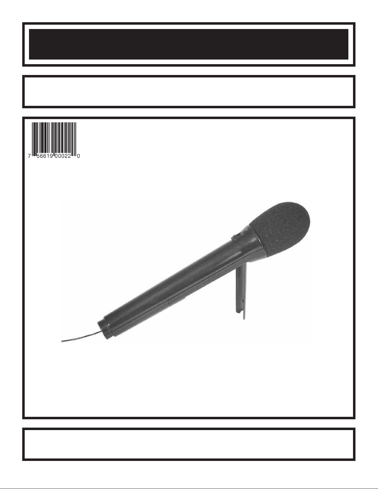
FM WIRELESS MICROPHONE KIT
MODEL K-30/AK-710
ight © 2006, 1994 b
yr
Cop
t of this book shall be reproduced b
No par
Assembly and Instruction Manual
Elenco®Electronics, Inc.
y Elenco
®
Electronics
y means; electronic, photocopying, or otherwise without written permission from the publisher.
y an
, Inc.
ights reser
All r
ved. Revised 2006 REV-J 753016
Page 2
PARTS LIST
If you are a student, and any parts are missing or damaged, please see instructor or bookstore.
If you purchased this kit from a distributor, catalog, etc., please contact Elenco®Electronics (address/phone/e-mail is at the
back of this manual) for additional assistance, if needed. DO NOT contact your place of purchase as they will not be able
to help you.
RESISTORS
Qty. Symbol Value Color Code Part #
1 R5 150Ω 5% 1/4W brown-green-brown-gold 131500
2 R8, R10 1kΩ 5% 1/4W brown-black-red-gold 141000
1 R7 1.5kΩ 5% 1/4W brown-green-red-gold 141500
1 R3 4.7kΩ 5% 1/4W yellow-violet-red-gold 144700
1 R1 8.2kΩ 5% 1/4W gray-red-red-gold 148200
1 R6 10kΩ 5% 1/4W brown-black-orange-gold 151000
1 R2 27kΩ 5% 1/4W red-violet-orange-gold 152700
2 R4, R9 47kΩ 5% 1/4W yellow-violet-orange-gold 154700
CAPACITORS
Qty. Symbol Value Description Part #
1 C4 10pF (10) Discap 211011
1 C5 12pF (12) Discap 211210
1 C6 33pF (33) Discap 213317
2 C3, C7 .001
2 C1, C2 .1
µF (102) Discap 231035
µF (104) Discap 251010
SEMICONDUCTORS
Qty. Symbol Value Description Part #
3 Q1 - Q3 2N3904 Transistor 323904
1 LED Light Emitting Diode (LED) 350001
1 Coil FM Mic 468751
MISCELLANEOUS
Qty. Description Part #
1 PC Board 517710
1 Switch (S1) 541024
1 Mic 568000
1 Battery Clip (+) 590091
1 Battery Clip (–) 590093
1 Foam Cover 620002
1 Top Case 623105
1 Bottom Case 623205
1 Stand 626010
Qty. Description Part #
1 Battery Cover 627002
1 Alignment Tool 629011
1 Screw 2.5mm x 4mm 641310
3 Screw 2.6 x 8mm 642109
12” Wire 22ga. Gray 814810
6” Wire 26ga. Black 816210
10.5” Wire 26ga. Red 816220
1 Solder Tube 9ST4
Caution: Do not mix alkaline, standard (carbon-zinc), or rechargeable (nickel-cadmium) batteries.
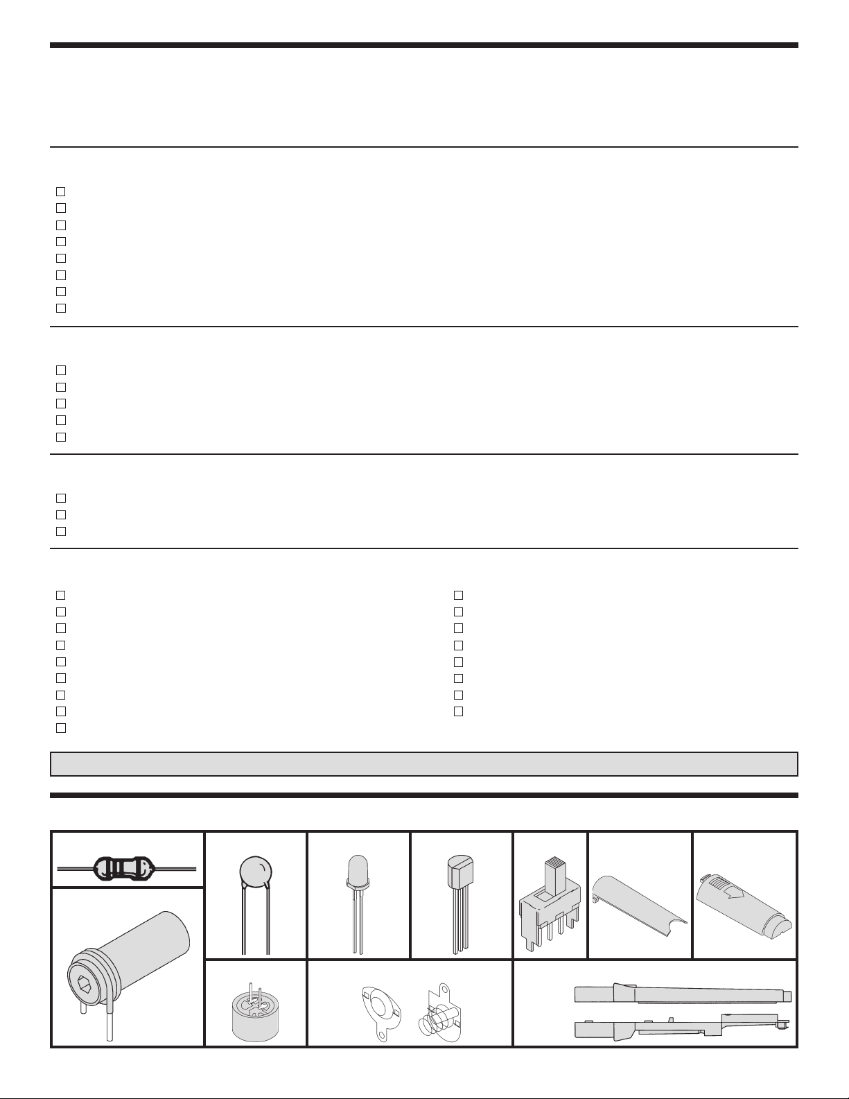
PARTS IDENTIFICATION
Resistor
Capacitor Transistor
SwitchLED
Stand
Battery Cover
FM Coil
Microphone
Battery Clips
-1-
Case
To p
(–)(+)
Bottom
Page 3
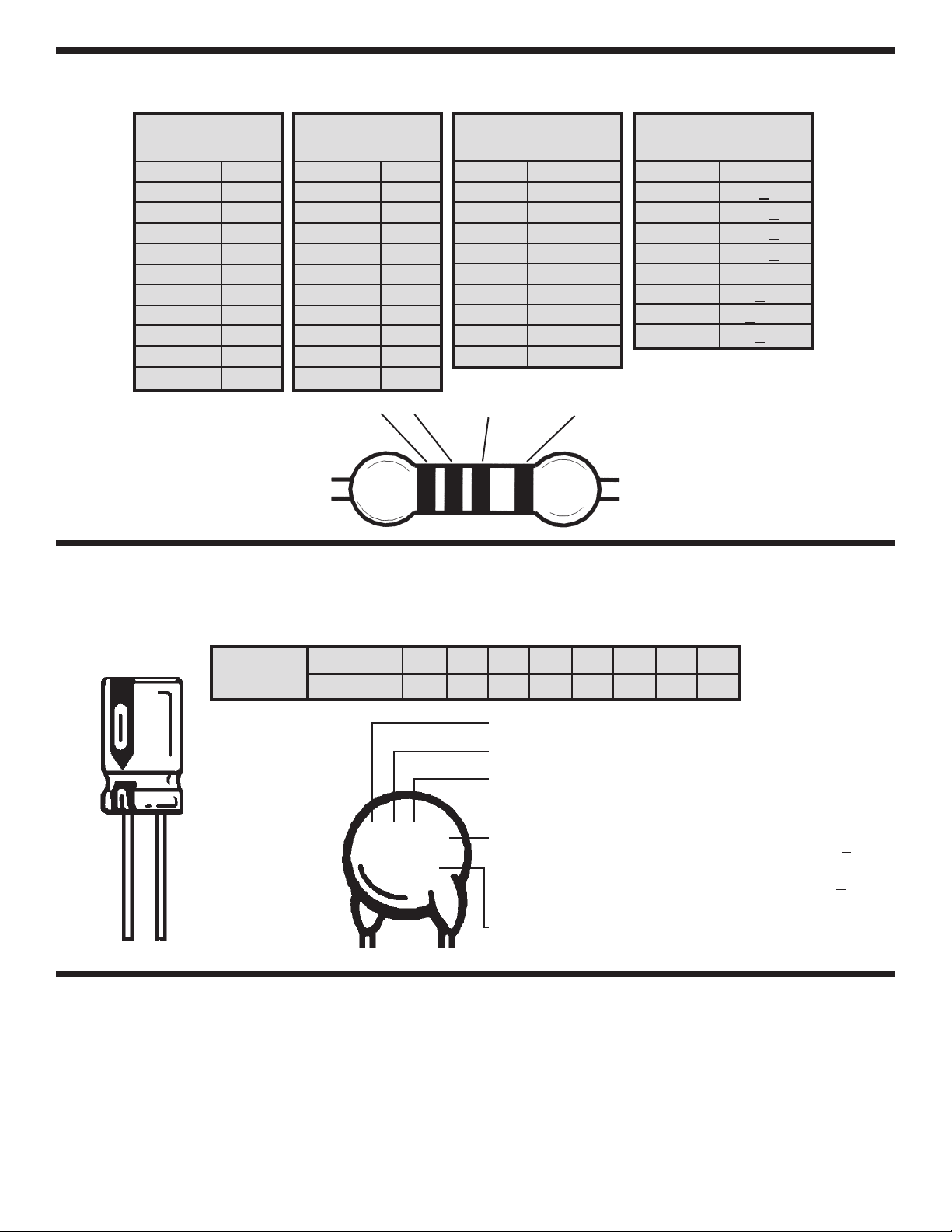
IDENTIFYING RESISTOR VALUES
Use the following information as a guide in properly identifying the value of resistors.
BAND 1
1st Digit
Color Digit
Black 0
Brown 1
Red 2
Orange 3
Yellow 4
Green 5
Blue 6
Violet 7
Gray 8
White 9
BANDS
BAND 2
2nd Digit
Color Digit
Black 0
Brown 1
Red 2
Orange 3
Yellow 4
Green 5
Blue 6
Violet 7
Gray 8
White 9
1
IDENTIFYING CAPACITOR VALUES
Multiplier
Color Multiplier
Black 1
Brown 10
Red 100
Orange 1,000
Yellow 10,000
Green 100,000
Blue 1,000,000
Silver 0.01
Gold 0.1
2 Multiplier Tolerance
Resistance
Tolerance
Color Tolerance
Silver +
Gold +5%
Brown +1%
Red +2%
Orange +3%
Green +
Blue +0.25%
Violet +0.1%
10%
0.5%
Capacitors will be identified by their capacitance value in pF (picofarads), nF (nanofarads), or µF (microfarads). Most
capacitors will have their actual value printed on them. Some capacitors may have their value printed in the following
manner. The maximum operating voltage may also be printed on the capacitor.
10µF 16V
Multiplier
The value is
10 x 1,000 =
10,000pF or
.01µF 100V
For the No.01234589
Multiply By 1 10 100 1k 10k 100k 0.01 0.1
Note: The letter “R” may be used at times
to signify a decimal point; as in 3R3 = 3.3
The letter M indicates a tolerance of +
The letter K indicates a toler
The letter J indicates a toler
103K
100V
First Digit
Second Digit
Multiplier
olerance
T
Maximum Working Voltage
20%
ance of +10%
ance of +5%
FM MICROPHONE KIT
Your FM Microphone is really a miniature frequency
modulated transmitter operating in the standard FM
ange of frequencies f
broadcast band.
FM broadcast band is 90MHz (MHz = Megahertz or
90 million cycles per second). Because the FM
microphone has a variable tuned circuit, it can be
tuned to a quiet spot on your local FM broadcast
band for the best reception. When the small
The r
or the
microphone element is struck by sound, it converts
the audio to a change in current through resistor R1
(see schematic diag
amplified and eventually frequency modulates the
transmitter. The transmission range of the FM
microphone is approximately 100 feet, depending
on the efficiency of the antenna (properly tuned or
not) and the quality of the FM radio receiver.
r
This electr
am).
ical change is
-2-
Page 4
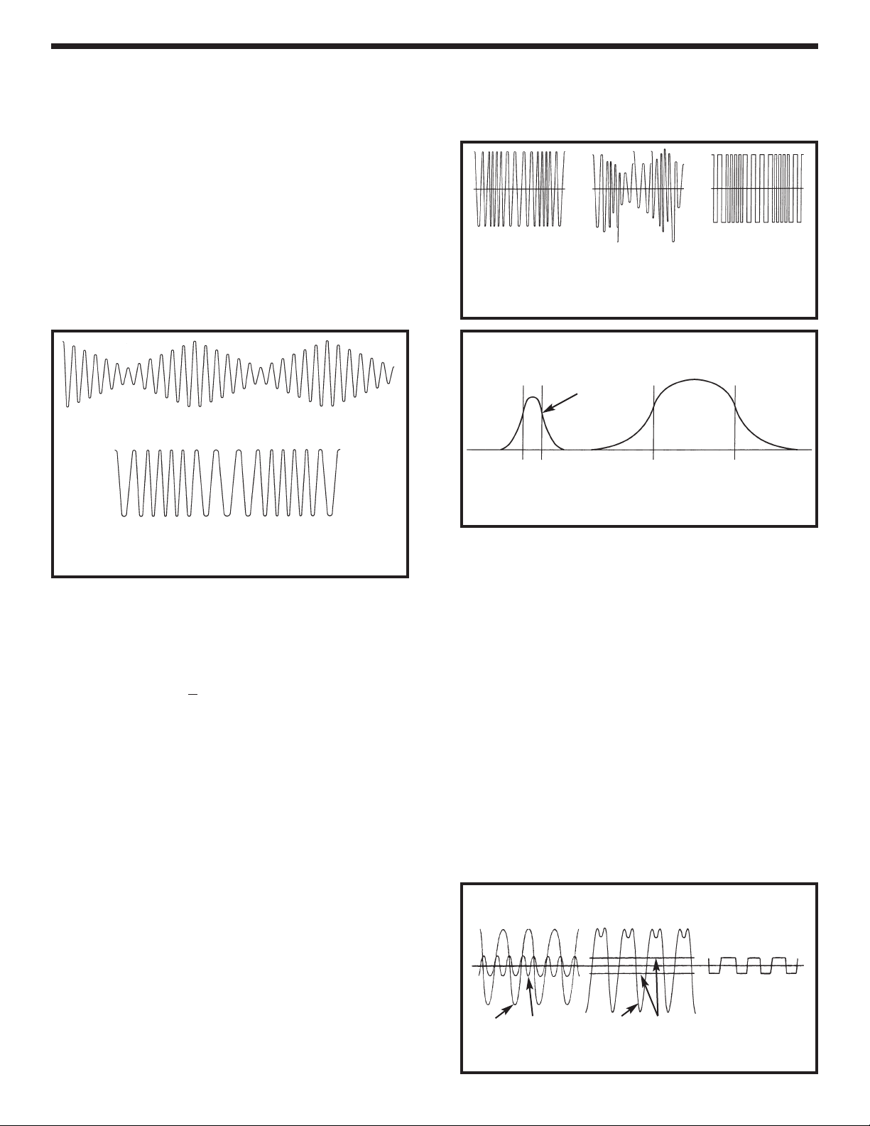
BASIC MODULATION THEORY
There are many different methods for modulating
information onto a radio wave. The two most
popular methods are Amplitude Modulation (AM)
and Frequency Modulation (FM). Figure 1 shows
the basic difference between these two methods. In
an amplitude modulated radio wave, the audio
information (voice) varies the amplitude of the RF
carrier. To recover this information, all that is
needed is a peak detector that follows the carrier
peaks. This is fairly easy to understand. In a
frequency modulated radio wave, the information
changes the frequency of the carrier as shown in
Figure 1.
Amplitude Modulation
Frequency Modulation
Figure 1
The amplitude of the radio frequency carrier wave
remains constant.
determines how far the frequency is moved from the
unmodulated carrier frequency. In a normal FM
radio broadcast, the maximum deviation from center
frequency is set at +
A soft sound ma
umber of times the carrier deviates from the
The n
center frequency, each second depends on the
frequency of the audio. For example, if the carrier is
moved to +75kHz, then –75kHz 1,000 times each
second, the carr
with a 1,000 cycle audio tone.
One advantage of FM modulation over AM
modulation is the carrier amplitude is not important
since the information is carried by the frequency.
This means that an
signal after transmission (such as lightning, spark or
ignition noise in cars, etc.) can be reduced by
allowing the amplifiers before detection to limit or
saturate. This principle is shown in Figure 2.
The loudness of the audio
150kHz for the loudest sound.
y move the carrier only +10kHz.
ier is 50% modulated f
or loudness
y amplitude noise added to the
broadcast band has only 7,000 Hertz band width
(Figure 3). The FM band is therefore considered to
be “High Fidelity” compared to the older AM band.
Original Transmitted
Signal
Received Signal with
Noise and Fading
Received Signal
After Limiting
Amplifier
Figure 2
Audio Bandwidth for AM & FM
Narrow Band
Wide
Bandwidth
7kHz 25kHz
AM Broadcast Band FM Broadcast Band
Figure 3
Another big advantage that FM has over AM is the
“Capture” effect in FM broadcast. If two different
broadcasts are very close in frequency or on the
same frequency in AM, they will produce an audio
eet or beat.
tw
strongest signal and ignore the weaker one. In
other words, if a local transmitter and another
distant tr
FM receiver will lock in on the strong local station
and reject the w
conditions e
between the two stations, which is very annoying.
Capture works because the receiver “sees” radio
ves as the sum of each frequency present. Since
a
w
FM only looks at frequency
be eliminated b
The detector “sees” only the strong signal after the
limiting amplifier has stripped the weak one away.
o Frequencies
w
T
Transmitted
In FM, the receiver will “Capture” the
ansmitter are on the same frequency, the
eak one. In an AM radio, if the same
xist, you will hear a beat (a whistle)
, the weaker signal can
y the limiter as shown in Figure 4.
What Limiter “sees” Capture Effect
Output from limiter
F1 only . . . F2 removed
The standard broadcast band f
or FM w
as also
designed to have an audio range up to 25,000 Hertz
(Hertz = cycles per second). The standard AM
F1 F2 F1 + F2 Limiter Levels
Figure 4
-3-
Page 5

CIRCUIT OPERATION
Figure 5 shows a block diagram of the FM wireless
microphone circuit. The microphone element in
Block 1 acts like a resistor that changes when
exposed to sound waves. The change in resistance
causes current through the microphone element to
change when sound waves apply pressure to its
surface. This action is similar to squeezing a garden
hose and watching the water through it decrease.
When the hose is released, the water through it will
increase. When sound waves hit the microphone
element, the electrical current through the element
will increase and decrease according to the pressure
(loudness) of the sound.
Microphone
Element
Audio
Amplifier
Radio
Frequency
Oscillator
Radio
Frequency
Amplifier
Antenna
Q1 Q2 Q3
Block 5Block 4Block 3Block 2Block 1
Figure 5
Block 2 is a transistor (Q1) used as an audio
amplifier. The signal from the micro-phone element
actor of 3. In
is increased in amplitude b
electronics, this action is described as transistor Q1
having an audio gain of 3.
Block 3 is a transistor (Q2) used as an oscillator. An
oscillator is an electronic circuit similar to the
pendulum in a grandfather cloc
pendulum is started in motion, it will use only a
small amount of energy from the main spring to
keep it s
winging at the exact same frequency. It is
this stable frequency rate that sets the time
accurately. If the weight is moved down the stick on
the pendulum, the swing takes longer if the
frequency is lo
k, the frequency increases. This is called tuning
stic
wer. If the weight is moved up the
the frequency of the pendulum. In electronics, an
oscillator circuit also has tunable elements. The
inductor in a tuned circuit is equivalent to the length
of the pendulum (see Figure 6).
Pendulum
Cir
y a f
k. Once the
Electronic Tuned
cuit in Oscillator
By changing the position of the iron core in the
inductor, the inductance can be changed to tune the
oscillator to a desired radio frequency, just like
changing the weight of the pendulum would change
its frequency. When sound strikes the microphone
element, it is converted to an electrical signal,
amplified and used to change the capacitance
(length of the pendulum) of the electronic oscillator’s
tuned circuit. This causes the frequency of the
oscillator to make slight changes at the same rate
as the sound striking the microphone. This effect is
known as frequency modulation.
Block 4 is a transistor used as a radio frequency
amplifier. This block amplifies the modulated signal
from the oscillator and acts as a buffer stage
between the antenna and the oscilator. If the
antenna were tied directly to the oscillator without
the buffer, any capacitance added to the antenna
(touching it with your finger for example) would
produce a large change in the frequency of
oscillation. The receiver would not be able to follow
this large change in frequency and would lose the
transmission.
Block 5 is the antenna. The antenna is also a tuned
element since the length of the antenna determines
how well it will radiate the modulated signal. An
antenna acts much lik
e a piece of string tied to a
wall and stretched tight. If you tap the string, a wave
will travel to the wall and part of the energy will go
into the wall and par
t will be reflected back (see
Figure 7A). If the length of the string is adjusted to
match the rate of tapping as shown in Figure 7B, the
all receives all of the energy because it is at a
w
node or proper multiple of the wavelength. In
electronics, the wall is similar to the space around
the antenna. By properly tuning the antenna, all of
ailable power in the antenna will be radiated
v
the a
into the space around the antenna.
k. A term used in electronics to describe the
bac
None will reflect
amount of power reflected back as a ratio of the
amount of power radiated is called “The Standing
Wave Ratio”.
Figure 7A
Weight
Length
C
Figure 6
L
C = Capacitance
L = Inductance
-4-
ating String
Vibr
Original Wave Reflected Wave
Node
Figure 7B
all
W
All energy goes
into the wall,
none is reflected.
Page 6

CONSTRUCTION
Introduction
The most important factor in assembling your FM Wireless Microphone is good soldering techniques. Using the
proper soldering iron is of prime importance. A small pencil type soldering iron of 25 - 40 watts is
recommended. The tip of the iron must be kept clean at all times and well tinned.
Safety Procedures
• Wear eye protection when soldering.
Locate soldering iron in an area where you do not have to go around it or reach over it.
•
• Do not hold solder in your mouth. Solder contains lead and is a toxic substance. Wash your hands
thoroughly after handling solder.
• Be sure that there is adequate ventilation present.
Assemble Components
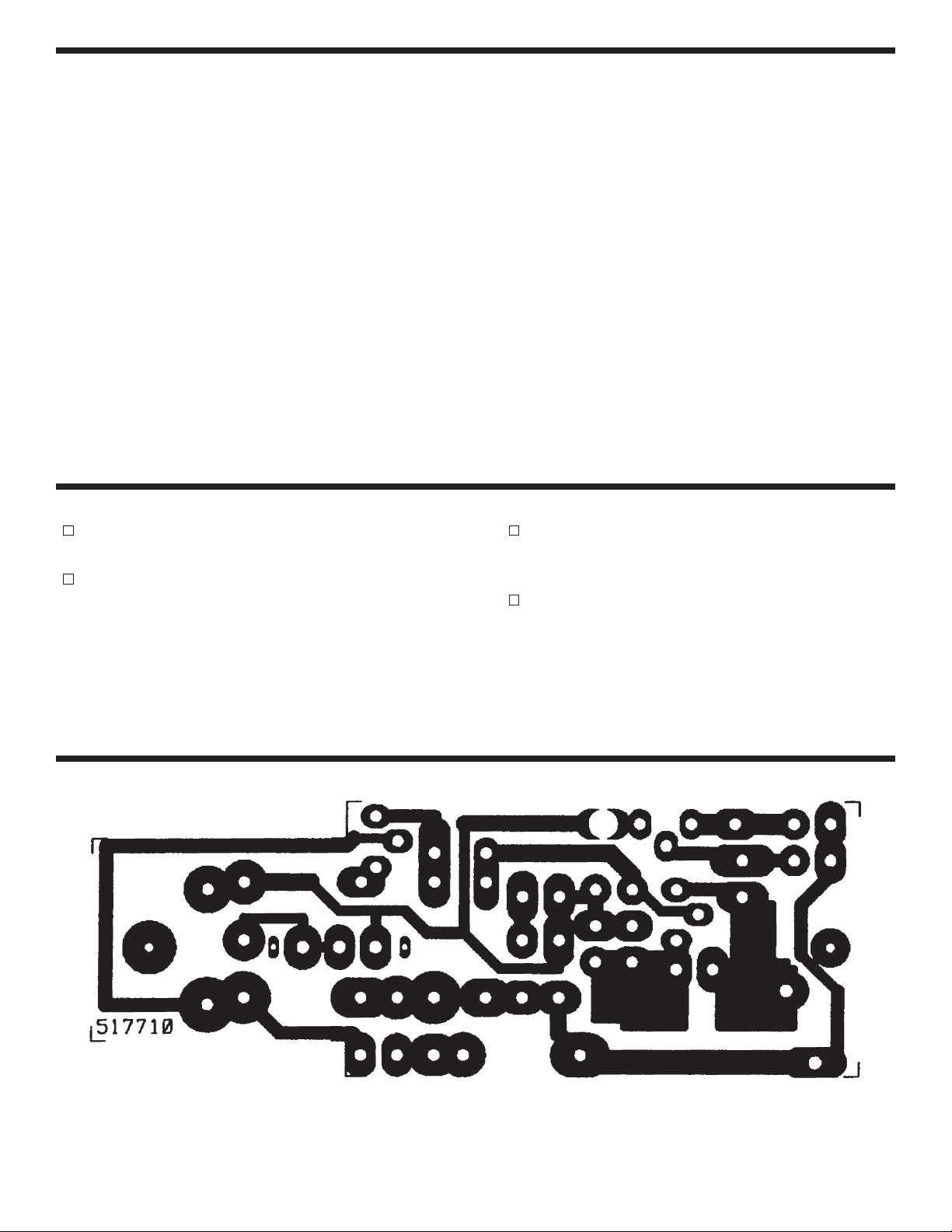
In all of the following assembly steps, the components must be installed on the top side of the PC board unless
otherwise indicated. The top legend shows where each component goes. The leads pass through the
corresponding holes in the board and are soldered on the foil side.
Use only rosin core solder of 63/37 alloy.
DO NOT USE ACID CORE SOLDER!
What Good Soldering Looks Like
A good solder connection should be bright, shiny,
smooth, and uniformly flowed over all surfaces.
1. Solder all components from
the copper foil side only.
Push the soldering iron tip
against both the lead and
the circuit board foil.
2. Apply a small amount of
solder to the iron tip. This
allows the heat to leave the
iron and onto the f
Immediately apply solder to
the opposite side of the
connection, away from the
iron. Allow the heated
component and the circuit
oil to melt the solder.
f
Allow the solder to flo
3.
around the connection.
Then, remove the solder
and the iron and let the
connection cool.
solder should have flowed
smoothly and not lump
around the wire lead.
4.
Here is what a good solder
connection looks like.
oil.
The
Component Lead
Foil
Solder
Foil
w
Solder
F
oil
Soldering Iron
Circuit Board
Soldering Iron
Soldering Iron
Types of Poor Soldering Connections
1. Insufficient heat - the
solder will not flow onto the
lead as shown.
2. Insufficient solder - let the
solder flow over the
connection until it is
vered. Use just enough
co
solder to co
connection.
3. Excessive solder - could
make connections that you
did not intend to between
adjacent foil areas or
minals.
ter
4. Solder bridges - occur
when solder runs between
circuit paths and creates a
short circuit. This is usually
caused by using too much
solder. To correct this,
simply dr
iron across the solder
bridge as shown.
ag y
ver the
our solder
ing
Rosin
Soldering iron positioned
incorrectly.
Solder
Component Lead
Solder
Solder
Foil
ing Iron
Dr
Gap
ag
-5-
Page 7

ASSEMBLE COMPONENTS TO THE PC BOARD
C4 - 10pF Discap (10)
Q2 - 2N3904 Transistor
(see Figure A)
L1 - Coil
C5 - 12pF Discap (12)
C6 - 33pF Discap (33)
R8 - 1kΩ 5% 1/4W Res.*
(brown-black-red-gold)
C7 - .001µF Discap (102)
R10 - 1kΩ 5% 1/4W Res.*
(brown-black-red-gold)
R1 - 8.2kΩ 5% 1/4W Res.
(gray-red-red-gold)
R4 - 47kΩ 5% 1/4W Res.
(yellow-violet-orange-gold)
R3 - 4.7kΩ 5% 1/4W Res.
(yellow-violet-red-gold)
C1 - .1µF Discap (104)
R2 - 27kΩ 5% 1/4W Res.
(red-violet-orange-gold)
Top Legend of PC Board
Mount
*
these
esistors
r
on end.
Mount the
transistor
with the
flat side
as shown
on the top
legend.
Figure A
R5 - 150Ω 5% 1/4W Res.*
(brown-green-brown-gold)
R9 - 47kΩ 5% 1/4W Res.*
(yellow-violet-orange-gold)
Q3 - 2N3904 Transistor
(see Figure A)
C3 - .001µF Discap (102)
C2 - .1µF Discap (104)
Q1 - 2N3904 Transistor
(see Figure A)
R7 - 1.5kΩ 5% 1/4W Res.
(brown-green-red-gold)
R6 - 10kΩ 5% 1/4W Res.
(brown-black-orange-gold)
Strip the insulation off of one end
of the 12” gray wire to expose 1/8”
of bare wire. Mount and solder the
wire to the foil side of the PC board
in hole J5.
Cut a 1 1/2” red wire and 1 1/2”
black wire. Strip the insulation off
of both ends to expose 1/8” of bare
wire. Mount and solder the red
wire to the foil side of the PC board
in hold J6 (+) and the black wire to
hole J7 (–).
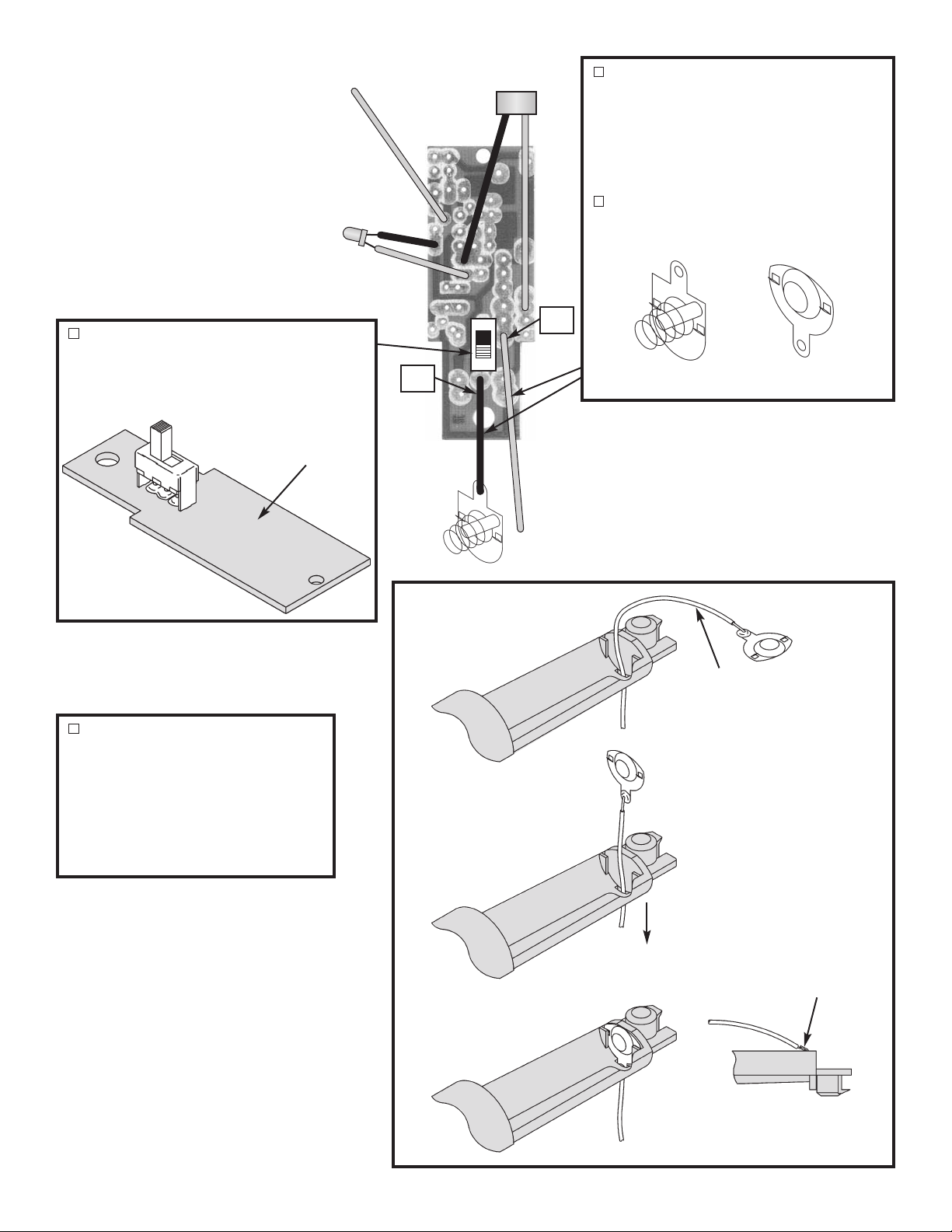
Cut the leads of the LED so that
they are 1/4” long, then spread
them slightly apar
Solder the free end of
k wire to the
lac
the b
flat side lead of the
Solder the free
.
LED
end of the red wire to
the other lead of the
.
LED
t (see Figure B).
Black
Flat
Figure B
Red
Foil Side of PC Board
J7 J2
J5
Black
Red
J6
If your microphone has leads attached
to it, cut them off flush with the pads on
the microphone. Cut a 2” piece of red
wire and a 2” piece of black wire. Strip
the insulation off of both ends to expose
1/8” of bare wire. Solder the red wire to
the foil side of the PC board in hole J1
(+) and the black wire to hole J2 (–).
Solder the free end of the red wire to
the (+) pad on the mic and the black
wire to the (–) pad on the mic as shown
in Figure C.
J1
+
Figure C
-6-
Page 8
F
oil Side of PC Board
Strip the insulation off of both ends on
he remaining 2 1/2” of black wire and the
t
7” of red wire to expose 1/8” of bare wire.
ount and solder the black wire to the
M
foil side of the PC board in hole J4 (–)
and the red wire in hole J3 (+).
Solder the free end of the black wire to
the negative (–) clip.
Mount the slide switch onto the foil side
of the PC board. The tabs on the switch
must go through the slots of the PC
board. Solder the switch to the PC
board.
Foil Side
Insert the free end of the red wire
through the slot in the bottom case
and solder to the positive (+) clip
(see Figure D).
J4
Figure D
J3
(–)
(+)
Red Wire
Pull the wire back through the slot and
insert the clip into the case and bend
the tab as shown in Figure E.
Figure E
Pull wire down
Bend tab
-7-
Page 9

FINAL ASSEMBLY
Insert the mic into the slot as shown in Figure F.
Insert the LED into the hole as shown in Figure F.
Place a piece of tape over the LED to hold it in
place.
Insert the PC board into the top case, as shown
in Figure G.
Insert the negative (–) battery clip into the bottom
case as shown in Figure G.
Press the gray antenna wire and the 7” piece of
red wire through the slots in the top case as
shown in Figure G.
Place the bottom case onto the top case. Hold
t
he two halves together with three 2.6 x 8mm
screws and one 2.5mm x 4mm screw, as shown
in Figure H.
Insert the stand in the case as shown in Figure H.
Push the foam cover onto the case as shown in
Figure H.
Insert two “AA” batteries into the case with the
positive (+) side toward the back end of the case
(see the inscription on the inside of the case).
Caution: Do not mix alkaline, standard (carbonzinc), or rechargeable (nickel-cadmium)
batteries. Insert the battery cover onto the case
as shown in Figure H.
Mic LED
Figure F
2.6 x 8mm Screws
Bottom Case
Top Case
Figure G
Stand
Red WireBlack Wire
Gray Antenna Wire
oam Cover
F
Battery Cover
2.6 x 8mm Screws
2.5 x 4mm Screw
Figure H
-8-
Page 10
OPERATING THE FM MIC
After assembling the kit, it will be necessary to tune
in the transmitter. First, be sure that all of the parts
are in correctly and that you have good solder
connections without any solder shorts.
Get an FM radio and tune it away from any FM
stations. You should hear only noise and no
programs. Place the unit about 2 feet from the radio
with the microphone facing the radio speaker.
Remove the foam cover and tune the RF coil with
the tuning stick and listen for a howl in the radio.
This indicates that you have tuned the transmitter to
the FM radio frequency. Place the transmitter away
from the radio until the howl disappears. Talk into
TROUBLESHOOTING
Tug slightly on all parts to make sure that they are
indeed soldered.
A solder bridge may occur if you accidently touch
an adjacent foil by using too much solder or by
agging the soldering iron across adjacent foils
dr
Break the bridge with your iron.
the microphone and you should hear your voice on
the radio. If your voice comes through the radio
distorted, speak softer (you are over-modulating).
Push the foam cover onto the case when tuned.
Have a friend listen to the radio and move the
transmitter about 100 feet away. Your voice should
still be heard over the radio. To obtain further
distance, add a longer antenna.
TO CONSERVE BATTERIES, TURN THE POWER
SWITCH OFF WHEN NOT ACTUALLY TALKING.
Make sure that all of the parts are placed in their
correct position. Check if the transistors’
orientations are correct.
Make sure that the polarity of the LED and
.
microphone are placed in the correct position.
FOIL SIDE OF PC BOARD
-9-
Page 11

SCHEMATIC DIAGRAM
GLOSSARY
Amplitude Modulation
Amplify To enlarge; increase in scope or
Antenna A device by which radio waves are
Audio Sounds that are capable of being
Buffer Stage A circuit used to insulate signals
Capacitor A device that is capable of holding
Capture The capacity of an FM receiver to
Carrier Wave The unmodulated wave radiated by
Deviation The change in frequency away from
Efficiency
Frequency Modulation
FM Broadcast Band The range of frequency where
ransmitter
T
FM
tz
Her
To modify the amplitude of the carrier
wave in accordance with the desired
signal, often abbreviated as AM.
volume.
released or received.
heard by the human ear.
from other circuits.
an electric charge.
pick only the strongest signal and
thus reduce co-channel
interference.
a broadcast station.
the carrier wave due to FM
modulation.
The ratio of energy e
power produced.
To modify the frequency of the carrier
e in accordance with the desired
v
a
w
signal, often abbreviated as FM.
commercial frequency modulation
ed by the Federal
is allo
Communications Commission
(FCC).
The sending appar
w
contained in the frequency of the
carrier wave.
A ter
of cycles per second.
w
ave in which the message is
m used to indicate the n
xpended to
atus of a r
umber
adio
High Fidelity A term used to indicate total
coverage of the hearing system.
Inductor A device capable of storing
electrical energy in the form of a
magnetic field.
MHz or Megahertz
Microphone A device used for producing an
Modulate To modify a characteristic of a
Noise In electronics, noise is usually the
Oscillator A device that continually swings
Peak Detector
endulum
P
Resistor An electric device used to restrict
RF Carrier The radio frequency wave used to
Saturate Completely charged or at its limit of
Standing Wave Ratio A term used in electronics to
Tuned Circuit
A million cycles per second.
electrical current corresponding in
its variations in air pressure of
sound.
carrier wave in accordance with the
characteristics of a desired signal.
random electrical signal produced
by the thermal agitation of atoms or
static discharges.
back and forth between two fixed
points.
A device used to recover the
modulated signal from an amplitude
modulated wave.
A body suspended from a fix
point so that it may swing freely.
w of electrical current.
the flo
“carry” the desired signal.
operation.
ibe the amount of po
descr
reflected bac
amount of power radiated.
A collection of components used to
select a single or small g
frequencies.
k as a ratio of the
ed
er
w
roup of
-10-
Page 12

QUIZ
1. The letters FM stand for ___________ ___________.
2. In AM transmissions, the audio information varies the _____________ of the radio frequency carrier wave.
3. In FM transmissions, the audio information varies the _____________ of the radio frequency carrier wave.
4. In a standard FM radio broadcast moving the carrier +
_____________% modulation.
5. The effect of rejecting the weaker station and accepting only the strong station is called ______________.
6. When the microphone is exposed to sound waves, it acts like a changing _____________.
7. An oscillator circuit is similar to the _______________ in a clock.
8. Sound striking the microphone is converted to an electrical signal, amplified, and used to change the
_____________ of the electronics oscillators tuned circuit.
9. Using an element to change the frequency of an oscillator at the same rate as the data to be transmitted is
called ____________ ____________.
10. The antenna is also a _____________ element.
75kHz from the center frequency would represent
7.
pendulum; 8. capacitance; 9. frequency modulation; 10. tuned
Answers: 1. frequency modulation; 2. amplitude; 3. frequency; 4. 50%; 5. capture; 6. resistor;
Elenco®Electronics, Inc.
150 Carpenter Avenue
Wheeling, IL 60090
(847) 541-3800
Web site: www.elenco.com
e-mail: elenco@elenco.com
 Loading...