

Page 1
Catalog # 28-287 REV-C Revised 2008 753296
Page 2

-1-
Basic Troubleshooting 1
How to Use It 2
Parts List 3, 4
About Your Snap KitsTMParts 5, 6
Advanced Troubleshooting 7, 8
DO’s and DON’Ts of Building Circuits 9
About the TWO-SPRING SOCKET (?1) 10
About the THREE-SPRING SOCKET (?Q) 11
Project Listings 12 - 14
Projects 1 - 303 15 - 126
Snap KitsTMExperiment Shapes 128
Other Radio Shack Projects 130
Table of Contents
1. Most circuit problems are due to incorrect assembly, always doublecheck that your circuit exactly matches the drawing for it.
2. Be sure that parts with positive/negative markings are positioned as
per the drawing.
3. Sometimes the light bulbs come loose, tighten them as needed. Use
care since glass bulbs can shatter.
4. Be sure that all connections are securely snapped.
5. Try replacing the batteries.
6. If the motor spins but does not balance the fan, check the black
plastic piece with three prongs on the motor shaft. Be sure that it is
at the top of the shaft.
Radio Shack is not responsible for parts damaged due to incorrect wiring.
Basic Troubleshooting
Note: If you suspect you have damaged parts, you can follow the Advanced
Troubleshooting procedure on page 7 to determine which ones need replacing.
Copyright © 2008 by Elenco®Electronics, Inc. All rights reserved. No part of this book shall be reproduced by any
means; electronic, photocopying, or otherwise without written permission from the publisher.
WARNING: SHOCK HAZARD - Never connect Snap KitsTMto the
electrical outlets in your home in any way!
WARNING: Always check your wiring
before turning on a circuit. Never leave a
circuit unattended while the batteries are
installed. Never connect additional
batteries or any other power sources to
your circuits. Discard any cracked or
broken parts.
WARNING TO ALL PARTS WITH A SYMBOL - Moving parts. Do not touch the motor or fan during operation.
Do not lean over the motor. Do not launch the fan at people, animals, or objects. Eye protection is recommended.
!
!
!
Batteries:
•
Use only 1.5V AA type, alkaline batteries (not incl.).
• Insert batteries with correct polarity.
• Non-rechargeable batteries should not be
recharged. Rechargeable batteries should only be
charged under adult supervision, and should not
be recharged while in the product.
• Do not mix alkaline, standard (carbon-zinc), or
rechargeable (nickel-cadmium) batteries.
• Do not mix old and new batteries.
• Remove batteries when they are used up.
• Do not short circuit the battery terminals.
• Never throw batteries in a fire or attempt to open its
outer casing.
• Batteries are harmful if swallowed, so keep away
from small children.
!
Page 3
-2-
The Radio Shack Snap KitsTMhas 303 projects. They are
simple to build and understand.
Snap Kits
TM
uses building blocks with snaps to build the
different electrical and electronic circuits in the projects. Each
block has a function: there are switch blocks, lamp blocks,
battery blocks, different length wire blocks, etc. These blocks
are in different colors and have numbers on them so that you
can easily identify them. The circuit you will build is shown in
color and numbers, identifying the blocks that you will use
and snap together to form a circuit.
For Example:
This is the switch block which is green and has the marking
on it as shown in the drawings. Please note that the drawing
doesn’t reflect the real switch block exactly (it is missing the ON
and OFF markings), but gives you the general idea of which
part is being used in the circuit.
This is a wire block which is blue and comes in different wire
lengths.
They have the number , , , , , or on them
depending on the length of the wire connection required.
There is also a 1-snap wire that is used as a spacer or for
interconnection between different layers.
To build each circuit, you have a power source block
number that needs two (2) “AA” batteries (not included
with Snap Kits
TM
).
A large clear plastic base grid is included with this kit to help
keep the circuit block together. You will see evenly spaced
posts that the different blocks snap into. You do not need this
base to build your circuits, but it does help in keeping your
circuit together neatly. The base has rows labeled A-G and
columns labeled 1-10.
Next to each part in every circuit drawing is a small number
in black. This tells you which level the component is placed
at. Place all parts on level 1 first, then all of the parts on level
2, then all of the parts on level 3, etc.
The 6V bulb comes packaged separate from its socket.
Install the bulb in the lamp socket whenever that part is
used.
Place the fan on the motor whenever that part is used,
unless the project you are building says not to use it.
Note: While building the projects, be careful not to
accidentally make a direct connection across the battery
holder (a “short circuit”), as this will damage and/or quickly
drain the batteries.
How To Use It
S1
2 3 4 5 7
M1
L2
B1
6
Page 4
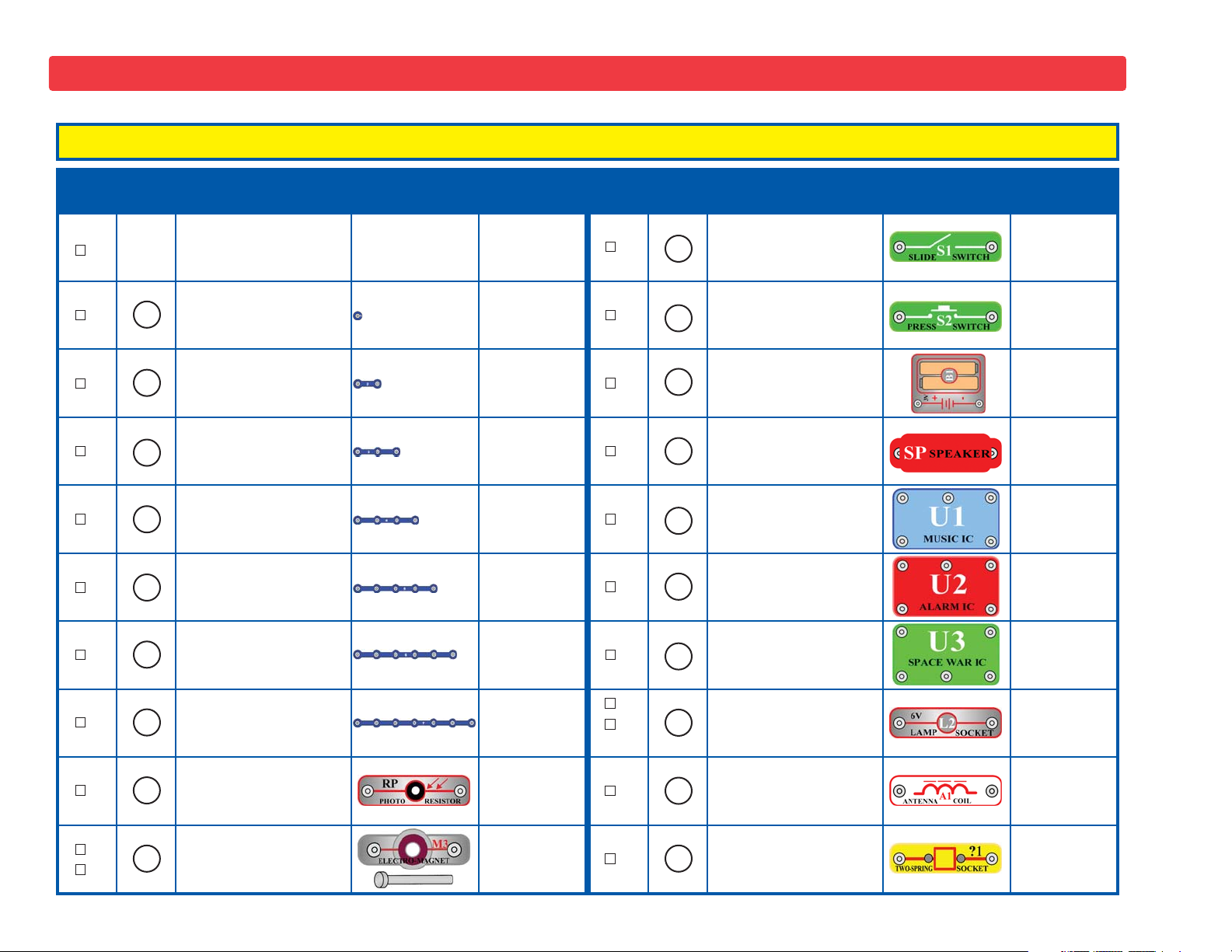
Qty. ID Name Symbol Part # Qty. ID Name Symbol Part #
1
Base Grid
(11.0” x 7.7”)
6SCBG 1 Slide Switch 6SCS1
6 1-Snap Wire 6SC01 1 Press Switch 6SCS2
9 2-Snap Wire 6SC02 2
Battery Holder - uses
two 1.5V type AA
(not included)
6SCB1
4 3-Snap Wire 6SC03 1 Speaker 6SCSP
2 4-Snap Wire 6SC04 1
Music
Integrated Circuit
6SCU1
1 5-Snap Wire 6SC05 1
Alarm
Integrated Circuit
6SCU2
1 6-Snap Wire 6SC06 1
Space War
Integrated Circuit
6SCU3
1 7-Snap Wire 6SC07
1
1
6V Lamp Socket
6V Bulb (6.2V, 0.3A)
(R. S. p/n 272-1130)
6SCL2
6SCL2B
1 Photoresistor 6SCRP 1 Antenna Coil 6SCA1
1
1
Electromagnet
Iron Core Rod
6SCM3
6SCM3B
2 Two-spring Socket 6SC?1
A1
L2
6
5
4
3
2
1
S1
S2
RP
U3
U2
U1
SP
B1
-3-
Parts List (Colors and styles may vary) Symbols and Numbers
Note: If you have model RS-303, then there are additional part lists in your other project manuals.
7
M3
?1
Important: If any parts are missing or damaged in shipping, DO NOT RETURN TO RADIO SHACK. Call toll-free 1-800-THE-SHACK.
Page 5
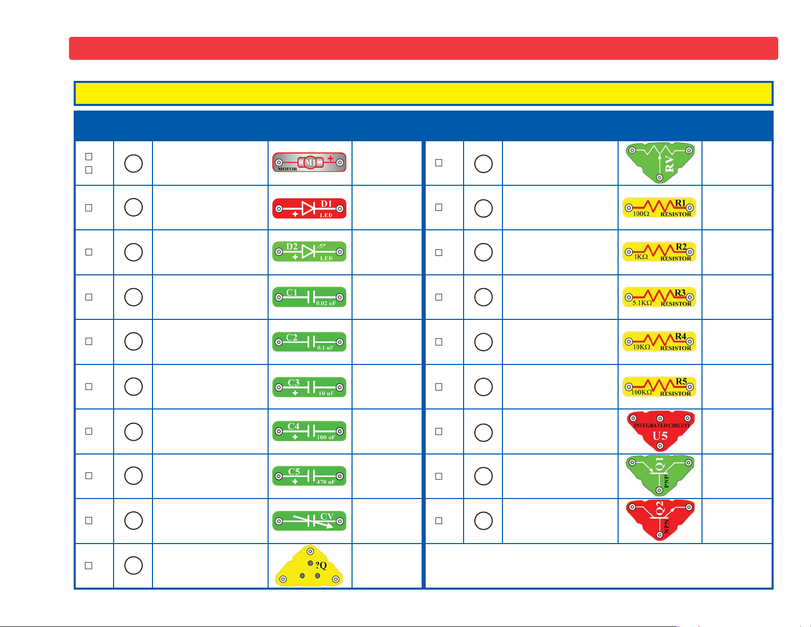
Qty. ID Name Symbol Part # Qty. ID Name Symbol Part #
1
1
Motor
Fan
6SCM1
6SCM1F
1 Adjustable Resistor 6SCRV
1
Red Light Emitting
Diode (LED)
6SCD1 1 100Ω Resistor 6SCR1
1
Green Light Emitting
Diode (LED)
6SCD2 1 1KΩ Resistor 6SCR2
1 0.02μF Capacitor 6SCC1 1 5.1kΩ Resistor 6SCR3
1 0.1μF Capacitor 6SCC2 1 10kΩ Resistor 6SCR4
1 10μF Capacitor 6SCC3 1 100kΩ Resistor 6SCR5
1 100μF Capacitor 6SCC4 1
High Frequency
Integrated Circuit
6SCU5
1 470μF Capacitor 6SCC5 1 PNP Transistor 6SCQ1
1 Variable Capacitor 6SCCV 1 NPN Transistor 6SCQ2
1 Three-spring Socket 6SC?Q
-4-
D2
C1
C2
U5
R5
R4
R3
C4
C3
Q1
Note: If you have model RS-303, then there are additional part lists in your other project manuals.
Parts List (Colors and styles may vary) Symbols and Numbers
D1
R1
R2
Q2
RV
CV
C5
M1
?Q
Important: If any parts are missing or damaged in shipping, DO NOT RETURN TO RADIO SHACK. Call toll-free 1-800-THE-SHACK.
Page 6

Note: If you have Model RS-303, there is additional information in
your other project manual.
The base grid functions like the printed circuit boards found in
most electronic products. It is a platform for mounting parts and
wires (though the wires are usually “printed” on the board).
The blue snap wires are just wires used to connect other
components, they are used to transport electricity and do not affect
circuit performance. They come in different lengths to allow orderly
arrangement of connections on the base grid.
The
batteries (B1) produce an electrical voltage using a chemical
reaction. This “voltage” can be thought of as electrical pressure,
pushing electrical “current” through a circuit. This voltage is much
lower and much safer than that used in your house wiring. Using
more batteries increases the “pressure” and so more electricity
flows.
The
slide switch (S1) connects (ON) or disconnects (OFF) the
wires in a circuit. When ON, it has no effect on circuit performance.
The press switch (S2) connects (pressed) or disconnects (not
pressed) the wires in a circuit, just like the slide switch does.
Resistors “resist” the flow of electricity and are used to control or
limit the electricity in a circuit. Snap KitsTMincludes 100Ω (R1), 1KΩ
(R2), 5.1KΩ (R3), 10KΩ (R4), and 100KΩ (R5) resistors
(“K”
symbolizes 1,000, so R2 is really 1,000Ω). Increasing circuit
resistance reduces the flow of electricity.
The
adjustable resistor (RV) is a 50KΩ resistor but with a center
tap that can be adjusted between 0Ω and 50KΩ. At the 0Ω setting,
the current must be limited by the other components in the circuit.
The
photoresistor (RP) is a light-sensitive resistor, its value
changes from nearly infinite in total darkness to about 1,000Ω
when a bright light shines on it.
A light bulb, such as in the
6V lamp (L2), contains a special wire
that glows bright when a large electric current passes through it.
Voltages above the bulb’s rating can burn out the wire.
The motor (M1) converts elecricity into mechanical motion.
Electricity is closely related to magnetism, and an electric current
flowing in a wire has a magnetic field similar to that of a very, very
tiny magnet. Inside the motor is three coils of wire with many loops.
If a large electric current flows through the loops, the magnetic
effects become concentrated enough to move the coils. The motor
has a magnet inside so, as the electricity moves the coils to align
them with the permanent magnet, the shaft spins.
The
speaker (SP) converts electricity into sound. It does this by
using the energy of a changing electrical signal to create
mechanical vibrations (using a coil and magnet similar to that in the
motor), these vibrations create variations in air pressure which
travel across the room. You “hear” sound when your ears feel these
air pressure variations.
The
red LED (D1) and green LED (D2) are light emitting diodes,
and may be thought of as special one-way light bulbs. In the
“forward” direction (indicated by the “arrow” in the symbol)
electricity flows if the voltage exceeds a turn-on threshold (about
1.5V); brightness then increases. A high current will burn out an
LED, so the current must be limited by other components in the
circuit. LED’s block electricity in the “reverse” direction.
Capacitors are components that can store electrical pressure
(voltage) for periods of time, higher values have more storage.
Because of this storage ability they block unchanging voltage
signals and pass fast changing voltages. Capacitors are used for
filtering and oscillation circuits. Snap Kits
TM
includes 0.02μF (C1),
0.1μF (C2), 10μF (C3), 10μF (C4), 470μF (C5) capacitors, and a
variable capacitor (CV).
The variable capacitor can be adjusted
from .00004 to .00022μF and is used in high frequency radio
circuits for tuning.
-5-
About Your Snap KitsTMParts (Part designs are subject to change without notice).
Page 7
-6-
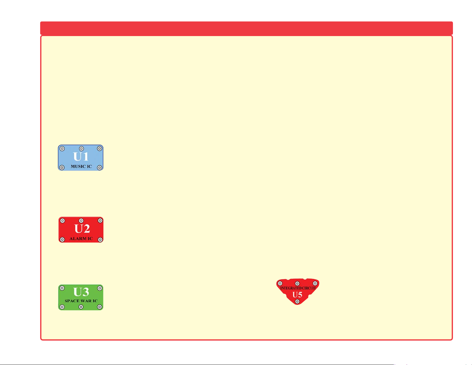
Some types of electronic components can be super-miniaturized,
allowing many thousands of parts to fit into an area smaller that
your fingernail. These “integrated circuits” (IC’s) are used in
everything from simple electronic toys to the most advanced
computers. The music, alarm, and space war IC’s (U1, U2, and
U3) in Snap Kits
TM
are actually modules containing specialized
sound-generation IC’s and other supporting components (resistors,
capacitors, and transistors) that are always needed with them. This
was done to simplify the connections you need to make to use
them. The descriptions for these modules are given here for those
interested, see the projects for connection examples:
The
antenna (A1) contains a coil of wire wrapped around an iron
bar. Although it has magnetic effects similar to those in the motor,
those effects are tiny and may be ignored except at high
frequencies (like in AM radio). Its magnetic properties allow it to
concentrate radio signals for reception. At lower frequencies the
antenna acts like an ordinary wire.
The
PNP (Q1) and NPN (Q2) transistors are components that
use a small electric current to control a large current, and are used
in switching, amplifier, and buffering applications. They are easy to
miniaturize, and are the main building blocks of integrated circuits
including the microprocessor and memory circuits in computers.
Projects #124-125 and #128-133 demonstrate their properties. A
high current may damage a transistor, so the current must be
limited by other components in the circuit.
The
electromagnet (M3) is a large coil of wire, which acts like a
magnet when a current flows through it. Placing an iron bar inside
increases the magnetic effects. Note that magnets can erase
magnetic media like floppy disks.
The
two-spring socket (?1) and 3-spring socket (?Q) are
described on pages 11-12.
The
high frequency IC (U5) is a specialized amplifier used only in
high frequency radio circuits. A description of it is given here for
those interested:
High Frequency IC:
INP - input connection (2 points are same)
OUT - output connection
(–) power return to batteries
See project #224 for example of
connections.
INP INP(–)
OUT
(+)
HLD
OUT
(–)
TRG
IN1
(–)
IN2
IN3
OUT
IN1
(+)
OUT
IN2
(–)
Music IC:
(+) - power from batteries
(–) - power return to batteries
OUT - output connection
HLD - hold control input
TRG - trigger control input
Music for ~20 sec on power-up, then hold
HLD to (+) power or touch TRG to (+)
power to resume music.
Space War IC:
(+) - power from batteries
(–) - power return to batteries
OUT - output connection
IN1, IN2 - control inputs
Connect each control input to (–) power to
sequence through 8 sounds.
Alarm IC:
IN1, IN2, IN3 - control inputs
(–) - power return to batteries
OUT - output connection
Connect control inputs to (+) power to
make five alarm sounds, see project #22
for configurations.
About Your Snap KitsTMParts (continued) (Part designs are subject to change without notice).
Page 8
-7-
Advanced Troubleshooting (Adult supervision recommended)
Radio Shack is not responsible for parts damaged due to incorrect
wiring.
If you suspect you have damaged parts, you can follow
this procedure to systematically determine which ones
need replacing:
1. 6V lamp (L2), motor (M1), speaker (SP), and battery holder
(B1):
Place batteries in holder and install bulb in lamp socket.
Place the 6V lamp directly across the battery holder, it should
light. Do the same with the motor (motor + to battery +), it should
spin to the right at high speed. “Tap” the speaker across the
battery holder contacts, you should hear static as it touches. If
none work, then replace your batteries and repeat. If still bad,
then the battery holder is damaged.
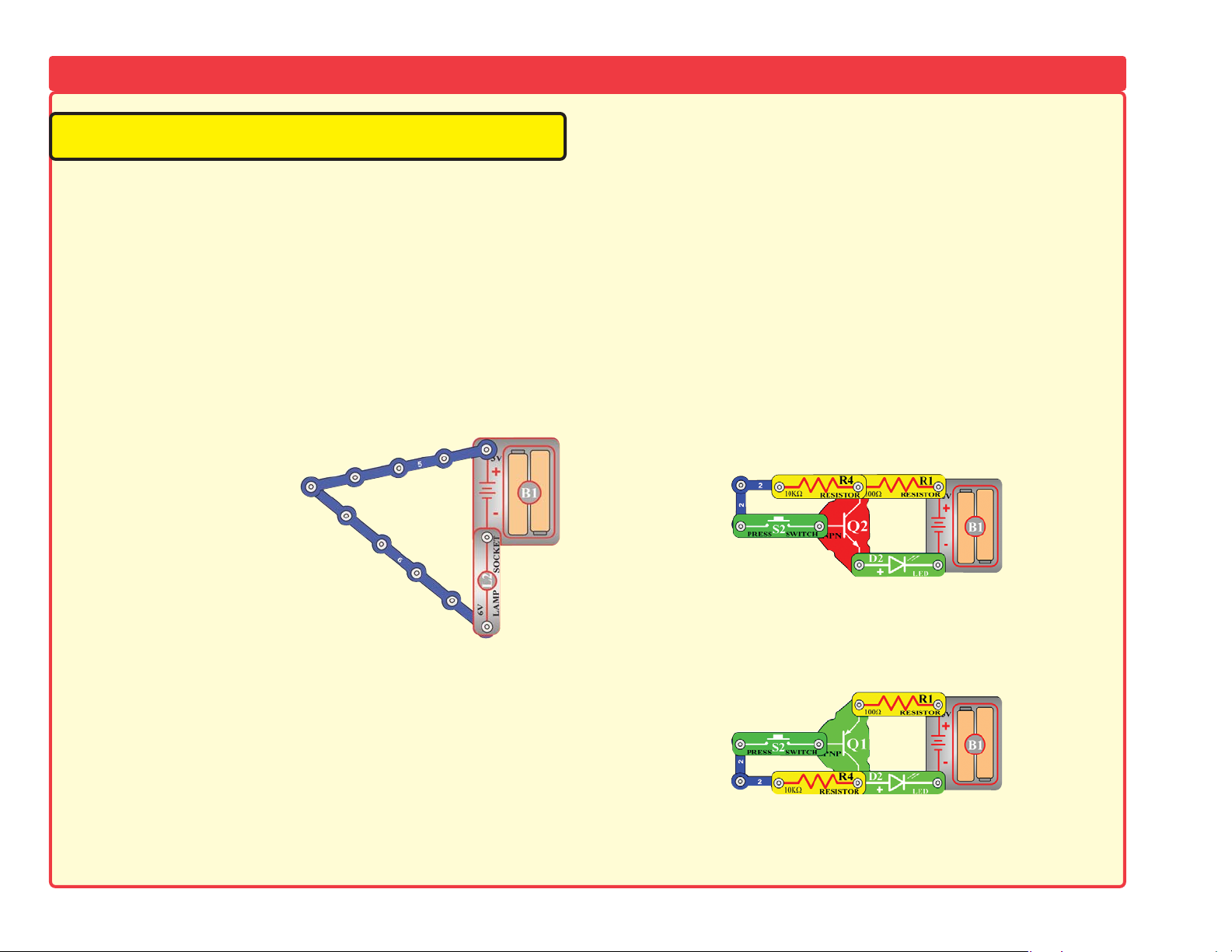
2.
Snap wires: Use this mini-
circuit to test the 5-snap
and 6-snap wires. The lamp
should light. Then test each
of the 1-snap, 2-snap, 3snap, 4-snap, and 7-snap
wires by connecting them
between the ends of the 5snap and 6-snap.
3.
Slide switch (S1) and Press switch (S2): Build project #1, if
the lamp (L2) doesn’t light then the slide switch is bad. Replace
the slide switch with the press switch to test it.
4.
LED’s (D1 & D2) and 100Ω (R1), 1KΩ (R2), 5.1KΩ (R3), and
10KΩ (R4) resistors:
Build project #7 except initially use the
speaker (SP) in place of the LED, you will hear static if the resistor
is good. Then replace the speaker with the LED and see if it lights.
Then, replace the 100Ω resistor with each of the other resistors,
the LED should light, but the brightness decreases with the higher
value resistors. Test the green LED in the same manner.
5. Alarm IC (U2): Build project #17, you should hear a siren. Then
place a 3-snap wire between grid locations A1 & C1, the sound
is different. Then move the 3-snap from A1-C1 to A3-C3 to hear
a third sound.
6.
Music IC (U1): Build project #74 but use the press switch (S2)
in place of the photoresistor (RP). Turn it on and the LED (D1)
flickers for a while and stops. It resumes if you press and hold
down the press switch. Then, touch a 3-snap wire across base
grid points A1 & C1 and the flickering resumes for a while.
7.
Space war IC (U3) and photoresistor (RP): Build project #19,
both switches (S1 & S2) should change the sound. Then replace
either switch with the photoresistor, waving your hand over it
should change the sound.
8.
NPN transistor (Q2): Build the mini-circuit shown here. The LED
(D2) should be on only when the press switch (S2) is pressed.
9.
PNP transistor (Q1): Build the mini-circuit shown here. The LED
(D2) should be on only when the press switch (S2) is pressed.
10. Antenna (A1): Build project #246, the LED (D1) should flash
when you release the press switch (S2).
Page 9
Advanced Troubleshooting (continued) (Adult supervision recommended)
11.
Adjustable resistor (RV): Build project #204 but use the 1KΩ
resistor (R2) in place of the photoresistor (RP). Turn on the slide
switch (S1), the resistor control can turn the LED (D1) on and off.
12. 100μF (C4) and 470μF capacitor (C5): Build project #49, then
press and release the press switch (S2). The LED (D1) should
go off slowly. Replace the 470μF with the 100μF and the LED
is only lit for about 4 seconds now.
13.
100KΩ resistor (R5) and 0.02μF (C1), 0.1μF (C2), and 10μF
(C3) capacitors:
Build project #163, but replace the 100KΩ
resistor with the photoresistor (RP) and cover it. You will hear
a whining or clicking sound unless the 0.02μF capacitor is bad.
Now place the 100KΩ resistor back in the circuit, you hear a
whining sound unless the 100KΩ is bad. Replace the 0.02μF
with the 0.1μF, the sound should be different (lower frequency)
or the 0.1μF is bad. Replace the 0.1μF with the 10μF, t h e
circuit will “click” about once a second unless the 10μF is bad.
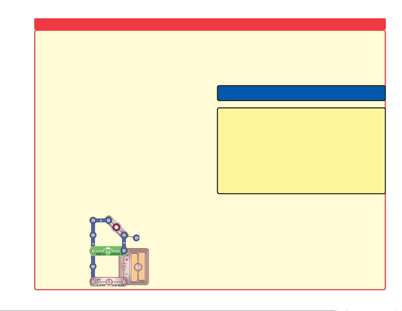
14.
Variable Capacitor (CV): Build project #169 and place it near
an AM radio, tune the radio and the capacitor to verify you hear
the music on your radio.
15.
High Frequency IC (U5): Build project #224 and adjust the
variable capacitor (CV) until you hear a radio station.
16.
Electromagnet (M3): Build the mini-circuit shown here. Lamp
(L2) must be dim, and must get brighter when you press the press
switch (S2).
Note: If you have RS-303, there are additional tests in your other
project manual.
For more information, contact:
Radio Shack Corporation
Fort Worth, TX 76102
Call us at
1-800-THE-SHACK
or visit us online at
www.radioshack.com
-8-
Page 10
-9-
DO’s and DON’Ts of Building Circuits
After building the circuits given in this booklet, you may wish to experiment on your
own. Use the projects in this booklet as a guide, as many important design
concepts are introduced throughout them. Every circuit will include a power
source (the batteries), a resistance (which might be a resistor, lamp, motor,
integrated circuit, etc.), and wiring paths between them and back.
You must be
careful not to create “short circuits” (very low-resistance paths across the
batteries, see examples below) as this will damage components and/or quickly
drain your batteries. Only connect the IC’s using configurations given in the
projects, incorrectly doing so may damage them. Radio Shack is not
responsible for parts damaged due to incorrect wiring.
Here are some important guidelines:
ALWAYS
use eye protection when experimenting on your own.
ALWAYS
include at least one component that will limit the current through a
circuit, such as the speaker, lamp, capacitors, IC’s (which must be
connected properly), motor, photoresistor, or resistors (the adjustable
resistor doesn’t count if it’s set at/near minimum resistance).
ALWAYS
use LED’s, transistors, the high frequency IC, the antenna, and
switches in conjunction with other components that will limit the current
through them. Failure to do so will create a short circuit and/or damage
those parts.
ALWAYS
connect the adjustable resistor so that if set to its 0 setting, the current
will be limited by other components in the circuit.
ALWAYS
connect position capacitors so that the “+” side gets the higher voltage.
ALWAYS
disconnect your batteries immediately and check your wiring if
something appears to be getting hot.
ALWAYS
check your wiring before turning on a circuit.
ALWAYS
connect IC’s using configurations given in the projects or as per the
connection descriptions for the parts.
NEVER
try to use the high frequency IC as a transistor (the packages are similar,
but the parts are different).
NEVER
connect to an electrical outlet in your home in any way.
NEVER
leave a circuit unattended when it is turned on.
NEVER
touch the motor when it is spinning at high speed.
For all of the projects given in this book, the parts may be arranged in different
ways without changing the circuit. For example, the order of parts connected in
series or in parallel does not matter — what matters is how combinations of these
sub-circuits are arranged together.
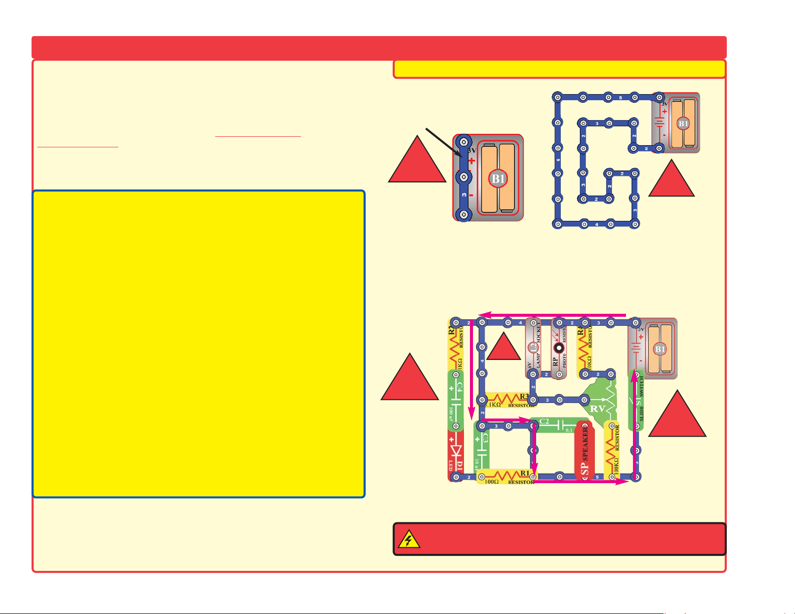
Examples of SHORT CIRCUITS - NEVER DO THESE!!!
WARNING: SHOCK HAZARD - Never connect Snap KitsTMto the
electrical outlets in your home in any way!
Placing a 3-snap wire directly
across the batteries is a
SHORT CIRCUIT.
This is also a
SHORT
CIRCUIT.
When the slide switch (S1) is turned on, this large circuit has a SHORT
CIRCUIT path (as shown by the arrows). The short circuit prevents any
other portions of the circuit from ever working.
!
!
!
!
NEVER
DO!
NEVER
DO!
NEVER
DO!
NEVER
DO!
NEVER
DO!
!
Page 11
-10-
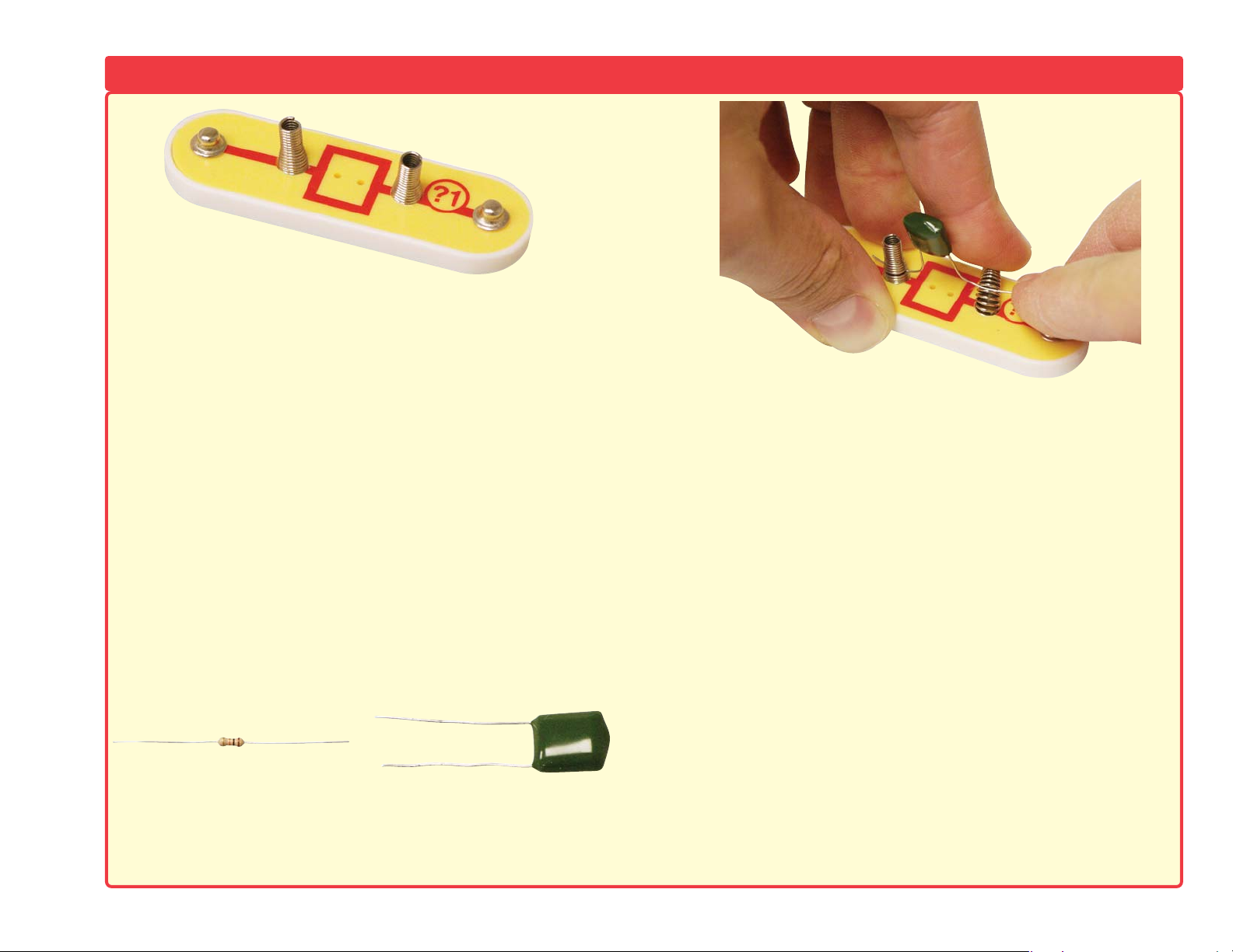
The two-spring socket (?1) just has two springs, and won’t do
anything by itself. It is not used in any of the experiments. It was
included to make it easy to connect other electronic components to
your Snap Kits
TM
. It should only be used by advanced users who
are creating their own circuits.
There are many different types of electronic components and basic
parts, like resistors and capacitors, that have a wide range of
available values. For example, your Snap Kits
TM
includes five fixedvalue resistors (100Ω, 1KΩ, 5.1KΩ, 10KΩ, and 100KΩ). This is a
very limited choice of values, and difficult to design circuits with.
Your Snap Kits
TM
also includes an adjustable resistor (RV), but it is
difficult to set this part to a particular value. You can place your
resistors in series and parallel to make different values, but this is
also difficult with only five values to choose from.
The two-spring socket (?1) makes it easy to connect your own
resistors (and other parts) to circuits by connecting them between
the springs:
Any component with two wires coming from it (called leads) can be
connected with the two-spring socket (?1), assuming the leads are
long enough. Usually you will connect different values of resistors
or capacitors, but other components like LED’s, diodes, or
coils/inductors can also be used. You can usually find electronic
components at any Radio Shack store.
You can design your own circuits or substitute new parts into the
projects in the manuals. For LED’s, diodes, or electrolytic
capacitors, be sure to connect your parts using the correct polarity
or you may damage them. Never exceed the voltage ratings of any
parts. RADIO SHACK IS NOT RESPONSIBLE FOR ANY PARTS
DAMAGED BY IMPROPER CIRCUIT DESIGN OR WIRING.
Never connect to external voltages. The two-spring socket is
only intended for advanced users.
About the TWO-SPRING SOCKET (?1)
Resistor Capacitor
Page 12
-11-
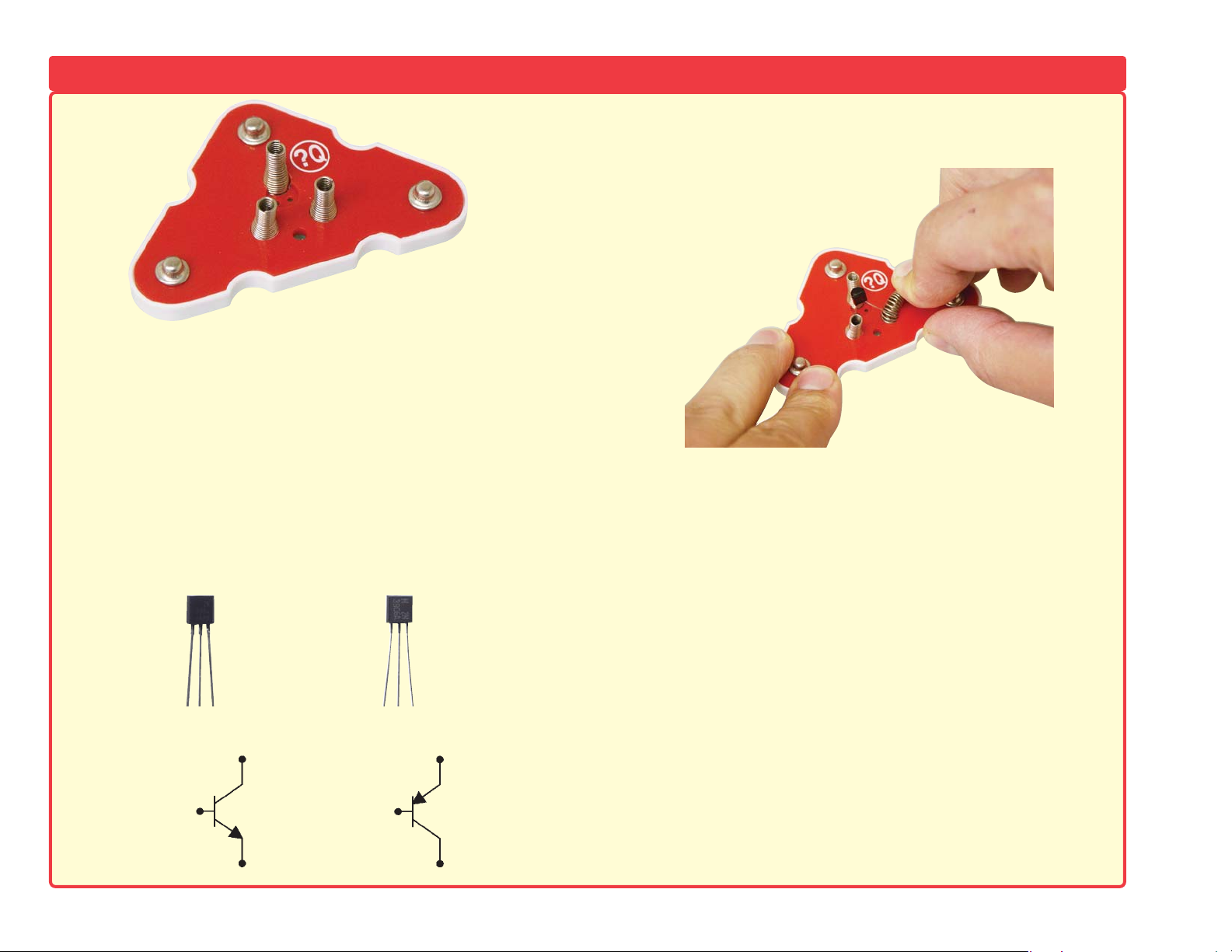
The three-spring socket (?Q) just has three springs, and won’t do
anything by itself. It is not used in any of the experiments. It was
included to make it easy to connect other electronic components to
your Snap Kits
TM
. It should only be used by advanced users who
are creating their own circuits.
There are many different types of transistors such as switching,
high gain, high frequency, high power, field-effect, and others. All
of these come with different specifications. Other common
components that have three connection points include adjustable
resistors, voltage regulator IC’s, SCR’s, some amplifier IC’s, some
types of inductors and filters, bi-color LED’s, and others.
The three-spring socket (?Q) makes it easy to connect your own
transistors (and other parts) to circuits by connecting them
between the springs:
Any component with three wires coming from it (called leads) can
be connected with the three-spring socket (?Q), assuming the
leads are long enough. Usually you will connect different types of
transistors, but other components with 3 leads can also be used.
You can find electronic components like this at Radio Shack.
You can design your own circuits or substitute new parts into the
projects in the manuals. Be sure to connect your parts correctly or
you may damage them. Never exceed the voltage ratings of any
parts. RADIO SHACK IS NOT RESPONSIBLE FOR ANY PARTS
DAMAGED BY IMPROPER CIRCUIT DESIGN OR WIRING.
Never connect to external voltages. The three-spring socket is
intended for advanced users only.
About the THREE-SPRING SOCKET (?Q)
NPN Transistor PNP Transistor
Collector
Base
Emitter
Emitter
Base
Collector
Page 13

-12-
Project # Description Page #
1 Electric Light & Switch 15
2 DC Motor & Switch 15
3 Hear the Motor 16
4 Adjusting Sound Level 16
5 Lamp & Fan in Series 17
6 Lamp & Fan in Parallel 17
7 Light Emitting Diode 18
8 One Direction for LED 18
9 Conduction Detector 19
10 Space War Alarm Combo 19
11 Flying Saucer 20
12 Decreasing Saucer Lift 20
13 Two-Speed Fan 21
14 The Fuse 21
15 Musical Doorbell 22
16 Momentary Alarm 22
17 Alarm Circuit 23
18 Laser Gun 23
19 Space War 24
20 Light Switch 24
21 Paper Space War 24
22 Light Police Siren 25
23 More Loud Sounds 25
24 More Loud Sounds (II) 25
25 More Loud Sounds (III) 25
26 More Loud Sounds (IV) 25
27 The Transistor 26
28 The Transistor (II) 26
29 The Transistor (III) 26
30 The Transistor (IV) 26
31 Sound Mixer 27
32 Sound Mixer (II) 27
33 Sound Mixer (III) 27
34 Sound Mixer (IV) 27
Project # Description Page #
35 Space Battle 28
36 Silent Space Battle 28
37 Periodic Sounds 28
38 Blinking Double Flashlight 28
39 Motor-controlled Sounds 29
40 More Motor Sounds 29
41 More Motor Sounds (II) 29
42 More Motor Sounds (III) 29
43 More Motor Sounds (IV) 29
44 Light-controlled Flicker 30
45 More Sound Effects 30
46 Slow Off Switch 31
47 Transistor Diodes 31
48 Four Outputs 31
49 Auto-off Night Light 32
50 Auto-off Night Light (II) 32
51 Reflection Detector 33
52 Quieter Reflection Detector 33
53 Flashing Laser Light with Sound 34
54 Space War Flicker 34
55 Spinning Rings 35
56 Strobe the House Lights 35
57 Race Game 36
58 Using Parts as Conductors 36
59 Spin Draw 37
60 Space War Flicker Motor 37
61 Speaker Static 38
62 Parallel Resistors 38
63 Series Resistors 38
64 The Transistor (V) 39
65 The Transistor (VI) 39
66 The Transistor (VII) 39
67 Simple Rectifier 40
68 Space War Music Combo 40
Project # Description Page #
69 Space War Siren 41
70 Sunrise Light 41
71 Light-controlled Lamp 42
72 Motor-controlled Lamp 42
73 Light NOR Gate 42
74 Light-controlled LED 43
75
Motor-controlled Time Delay LED
43
76 Capacitor Slow-down 43
77 Space War Flicker LED 44
78 Human Space War 44
79 Flash & Tone 44
80
Fan Blade Storing Energy
45
81 Speaker
Storing Energy
45
82 NPN Light Control 45
83 Fun with the Alarm IC 46
84 Musical Motor 46
85 Musical Light 46
86 Music Alarm Combo 47
87 Bomb Sound 47
88 Bomb Sound (II) 47
89 Motor Sounds Combo 48
90 Motor Sounds Combo (II) 48
91 Fan Detector 49
92 Slow Siren Changer 49
93 Capacitor Photo Control 50
94 Capacitor Control 50
95 Photo Space War with LED 51
96 Alarm Rectifier 51
97 Light-controlled Alarm 52
98 Fading Siren 52
99 Lamp & Fan Independent 53
100 Motor Space Sounds 53
101 Motor Space Light 53
102 Automatic Street Lamp 54
Project Listings
Page 14

Project # Description Page #
103 Pitch 54
104 Pitch (II) 54
105 Pitch (III) 54
106 Space War Sounds 55
107
Space War Sounds Controlled by Light
55
108 Adjustable Tone Generator 56
109 Photosensitive Electronic Organ 56
110 Electronic Cicada 56
111 Space War Radio 57
112 The Lie Detector 57
113 NPN Amplifier 58
114 PNP Amplifier 58
115 Sucking Fan 59
116 Blowing Fan 59
117 PNP Collector 59
118 PNP Emitter 59
119 NPN Collector 60
120 NPN Emitter 60
121 NPN Collector - Motor 60
122 NPN Emitter - Motor 60
123 Buzzing in the Dark 61
124 Touch Buzzer 61
125 High-Frequency Touch Buzzer 61
126 Mosquito 61
127 Loud Mosquito 61
128 Radio Music Alarm 62
129 Daylight Music Radio 62
130 Night Music Radio 62
131 Night Gun Radio 62
132 Radio Gun Alarm 62
133 Daylight Gun Radio 62
134 Fire Fan Symphony 63
135 Fan Symphony 63
136 Police Car Symphony 64
Project # Description Page #
137 Ambulance Symphony 64
138 Static Symphony 65
139 Static Symphony (II) 65
140 Capacitors in Series 65
141 Capacitors in Parallel 65
142 Current Controllers 66
143 NPN Dark Control 66
144 PNP Light Control 66
145 PNP Dark Control 66
146 Whining Fan 67
147 Light Whining 67
148 More Light Whining 67
149 Motor That Won’t Start 67
150 Current Equalizing 68
151 Lazy Fan 68
152 Laser Light 68
153 Whiner 69
154 Hummer 69
155 Adjustable Metronome 69
156 Quiet Flasher 69
157 HIssing Foghorn 70
158 Hissing & Clicking 70
159 Video Game Engine Sound 70
160 Make Your Own Battery 71
161 Make Your Own Battery (II) 71
162 Make Your Own Battery (III) 71
163 Tone Generator 72
164 Tone Generator (II) 72
165 Tone Generator (III) 72
166 More Tone Generator 73
167 More Tone Generator (II) 73
168 Radio Announcer 73
169 Music Radio Station 74
170 Alarm Radio Station 74
Project # Description Page #
171 Standard Transistor Circuit 74
172 Motor & Lamp by Sound 75
173 Fast Fade Siren 75
174 Changing Siren 76
175 Symphony of Sounds 76
176 Transistor Amplifiers 77
177 Pressure Meter 77
178 Resistance Meter 77
179 Auto-off Night Light (III) 78
180 Discharging Caps 78
181 Morse Code Generator 79
182 LED Code Teacher 79
183 Ghost Shriek Machine 79
184 LED & Speaker 79
185 Dog Whistle 79
186 Mind Reading Game 80
187 Enhanced Quiet Zone Game 81
188 Capacitor Charge & Discharge 81
189 Two-Finger Touch Lamp 82
190 One-Finger Touch Lamp 82
191 Space Battle 83
192 Space Battle (II) 83
193 Multi-speed Light Fan 83
194 Light & Finger Light 83
195 Storing Electricity 84
196 Lamp Brightness Control 84
197 Electric Fan 84
198 Fire Engine Symphony 85
199 Light Dimmer 85
200 Motion Detector 86
201 Fan Modulator 86
202 Oscillator 0.5 - 30Hz 87
203 Sound-pulse Oscillator 87
204 Motion Detector (II) 87
-13-
Project Listings
Page 15

-14-
Project # Description Page #
205 Motor Rotation 88
206 Motor Delay Fan 88
207 Motor Delay Fan (II) 88
208 High-pitch Bell 89
209 Steamship 89
210 Wet Finger Detector 89
211 Motor-activated Burglar Alarm 90
212 Light-activated Burglar Alarm 90
213 Spacey Fan 90
214 LED Fan Rotation Indicator 91
215 Space War Sounds with LED 91
216 Photoresistor Control 92
217 Sound Mixer Fan Driver 92
218 Electric Fan Stopped by Light 93
219 Motor & Lamp 93
220 Start-stop Delay 94
221 Mail Notifying System 94
222 Mail Notifying Electronic Bell 95
223 Mail Notifying Electronic Lamp 95
224 AM Radio with Transistors 95
225 Lasting Doorbell 96
226 Lasting Clicking 96
227 Delayed Action Lamp 96
228 Delayed Action Fan 96
229 Adjustable Time Delay Lamp 97
230 Adjustable Time Delay Fan 97
231 Transistor Fading Siren 97
232 Fading Doorbell 97
233 Adjustable Time Delay Lamp (II) 98
234 Adjustable Time Delay Fan (II) 98
235 Watch Light 98
236 Delayed Bedside Fan 98
237 This OR That 99
238 This AND That 99
Project # Description Page #
239 Neither This NOR That 100
240 NOT This AND That 100
241 Music AND Gate 101
242
Lamp, Speaker & Fan in Parallel
101
243 Light-controlled LED (II) 102
244 AM Radio 102
245 Transistor AM Radio 103
246 Antenna Storing Energy 103
247 Back EMF 104
248
Flashing Laser LED’s with Sound
104
249 Electromagnet Delayer 105
250
Photoresistor Paper Clip Suspension
105
251 Electromagnetism 106
252 Electromagnetism & Compass 107
253 Electromagnet Storing Energy 107
254 Electromagnet Tower 108
255 Paper Clip Compass 108
256 Paper Clip Oscillator (II) 109
257 Paper Clip Oscillator (III) 109
258 Paper Clip Oscillator (IV) 110
259 Paper Clip Oscillator (V) 110
260 Oscillating Compass 110
261 Siren Paper Clip Vibrator 111
262 Alarm Paper Clip Vibrator 111
263
Machine Gun Paper Clip Vibrator
111
264 Alarm Vibrator w/ LED 112
265 Alarm Vibrator w/ LED (II) 112
266 Motor Oscillator 113
267 Motor Oscillator (II) 113
268 Motor Oscillator (III) 113
269 Two-speed Motor Lights 114
270 Two-speed Motor Lights-Sound 114
271 Short-time Sound 115
272 Slow Light Dimmer 115
Project # Description Page #
273 Fading Bomb Sound 116
274 Fading Music Sound 116
275 Fading Music Sound (II) 116
276 Sound & Lights 117
277 Music with Timer 117
278 Motor Tone Generator 118
279 Motor Tone Generator (II) 118
280 Motor Tone Generator (III) 118
281 Motor Tone Generator (IV) 118
282 Turn Off Timer 119
283 Turn Off Timer (II) 119
284 LED & Bulb Timer 119
285 Alarm Timer 120
286 Alarm Timer (II) 120
287 Alarm Timer (III) 120
288 Space War Timer 121
289 Alarm Speed Adjuster 121
290 The SCR 122
291 Light-controlled SCR 122
292 Light-controlled SCR (II) 122
293 Light-controlled SCR (III) 122
294 LED Control Motor 123
295 LED Control Motor (II) 123
296 Light Oscillator 124
297
Sound, Light & Motor Stepper Circuit
124
298 Blink & Beep 125
299 Blink & Beep (II) 125
300 Simple Rectifier (II) 125
301 Alarm Motor 126
302 Alarm Light 126
303 Mirror Circuit 126
Project Listings
Page 16
-15-
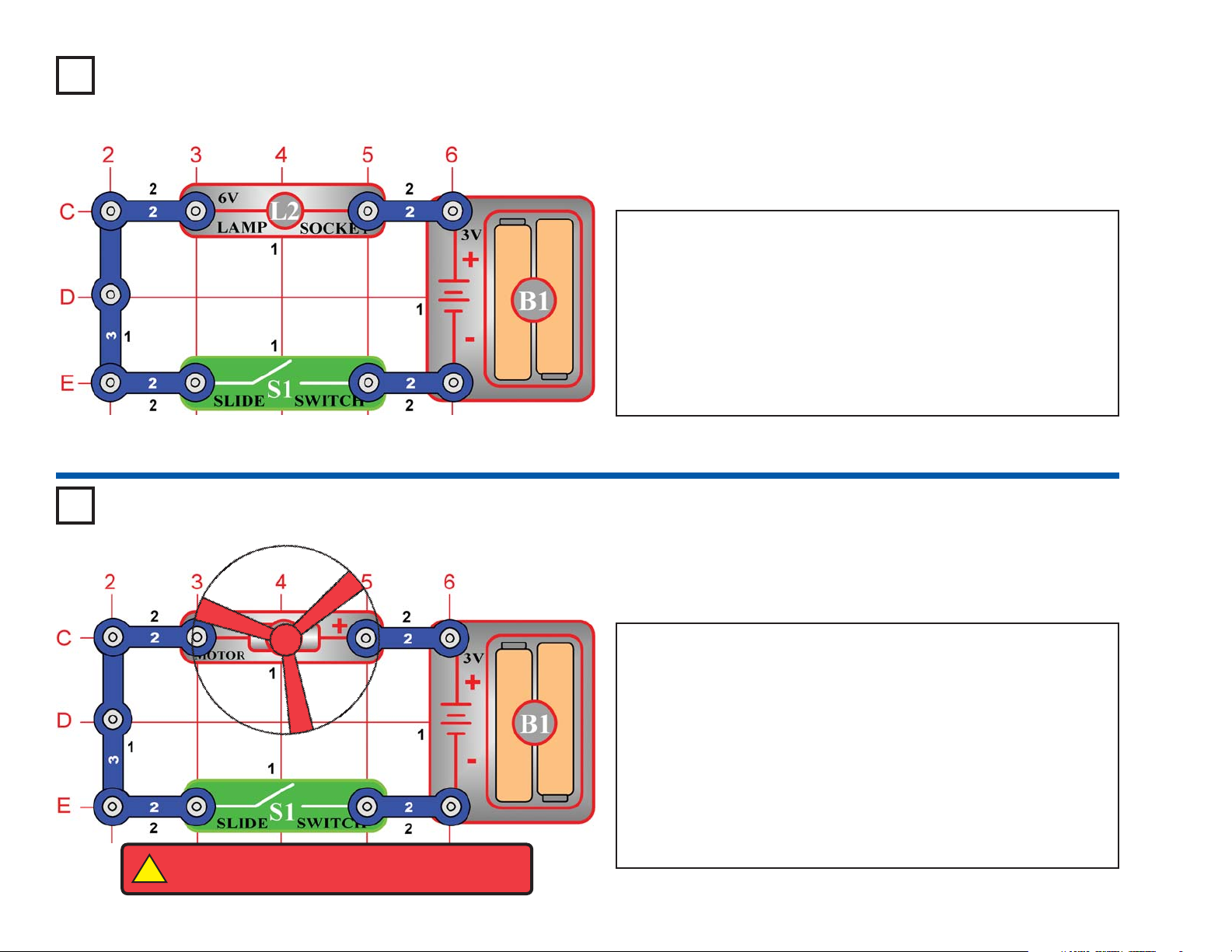
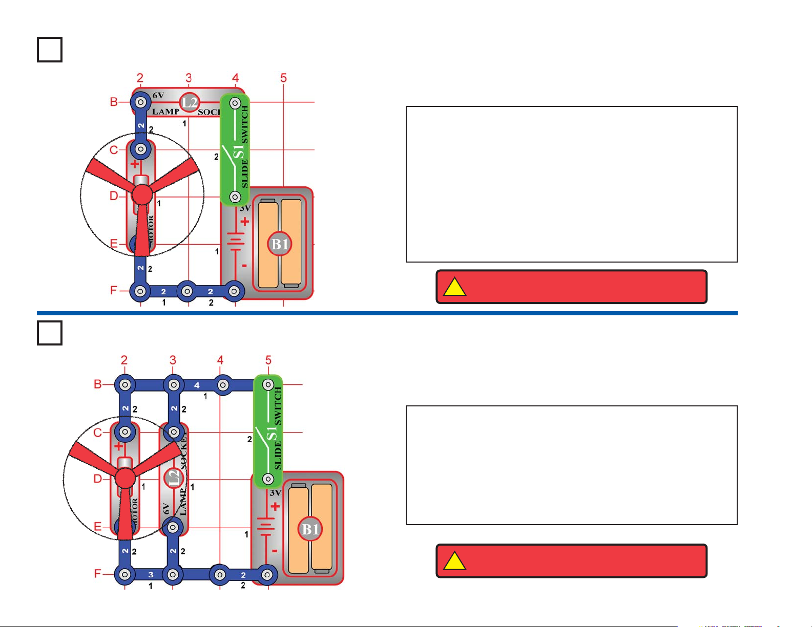
Project #1
OBJECTIVE: To show how electricity is turned “ON” or “OFF”
with a switch.
Electric Light & Switch
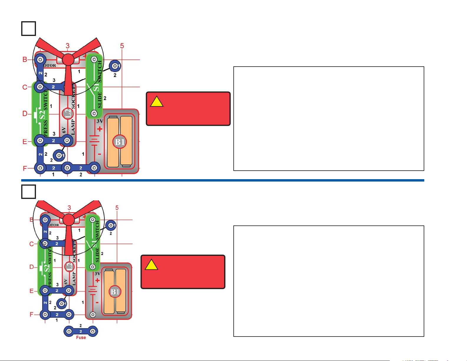
Project #2
OBJECTIVE: To show how electricity is used to run a direct
current (DC) motor.
Build the circuit shown on the left by placing all the parts with a black 1
next to them on the
base
first. Then, assemble parts marked with a 2.
When you turn on the slide switch (S1), current flows from the batteries
through the motor making it rotate. Place the fan blade on the motor
shaft and close the slide switch. The motor (M1) will rotate forcing the
fan blade to move air past the motor.
In this project, you changed electrical power into mechanical power.
DC motors are used in all the battery powered equipment requiring
rotary motion, such as a cordless drill, electric tooth brush, and toy
trains that run on batteries just to name a few. An electric motor is
much easier to control than gas or diesel engines.
DC Motor & Switch
Build the circuit shown on the left by placing all the parts with a black 1
next to them on the base first. Then, assemble parts marked with a 2.
Install two (2) “AA” batteries (not included) into the battery holder (B1)
and screw the bulb into the lamp socket (L2) if you have not done so
already.
When you turn on the slide switch (S1), current flows from the batteries
through the lamp and back to the battery through the switch. The closed
switch completes the circuit. In electronics this is called a closed circuit.
When the switch is opened, the current can no longer flow back to the
battery, so the lamp goes out. In electronics this is called an open circuit.
!
WARNING: Moving parts. Do not touch the fan or
motor during operation.
Page 17
-16-
Project #4
OBJECTIVE: To show how resistance can change the sound
from the speaker.
Build the circuit shown on the left, but leave the fan off the motor (M1).
When you turn on the slide switch (S1), the music may play for a short
time and then stop. After the music has stopped, spin the motor with
your fingers. The music should play again for a short time, then stop.
Now replace the 100Ω resistor (R1) with a 3-snap wire, and notice how
the sound is affected.
In this project, you changed the amount of current that goes through
the speaker (SP) and increased the sound output of the speaker.
Resistors are used throughout electronics to limit the amount of
current that flows.
Adjusting Sound Level
Project #3
OBJECTIVE: To show how a motor works.
Hear the Motor
Place the fan on the motor (M1). Press the press switch (S2) and
listen to the motor. Why does the motor make sound?
A motor uses magnetism to convert electrical energy into mechanical
spinning motion. As the motor shaft spins around it connects/
disconnects several sets of electrical contacts to give the best
magnetic properties. As these contacts are switched, an electrical
disturbance is created, which the speaker (SP) converts into sound.
If you replace the motor with the 6V lamp (L2), then it will work the
same, but only make noise when the lamp is turned ON or OFF.
Page 18
-17-
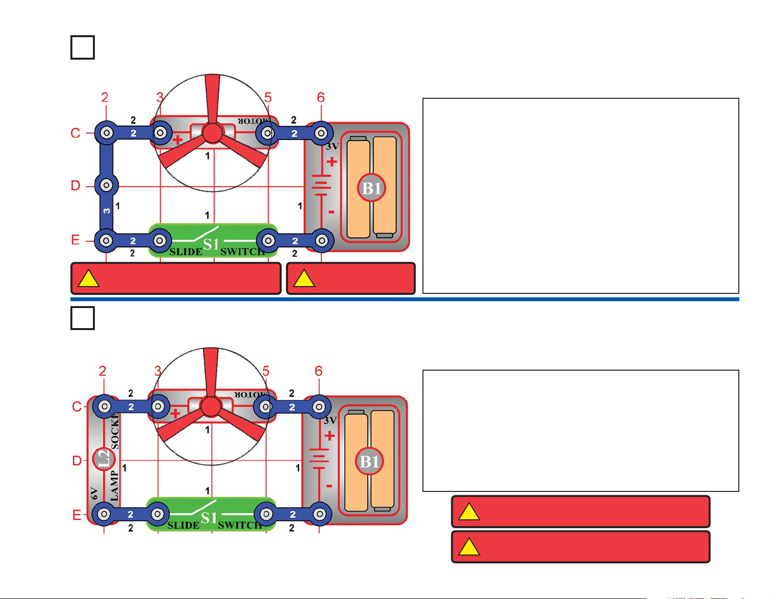
Project #5
OBJECTIVE: To show how a lamp can indicate when a fan is
running.
Build the circuit shown on the left by placing all the parts with a black 1
next to them on the base first. Then, assemble parts marked with a 2.
Finally, place the fan blade on the motor (M1).
When you turn on the slide switch (S1), the fan will spin and the lamp
(L2) should turn on. The fan will take a while to start turning due to
inertia. Inertia is the property that tries to keep a body at rest from
moving and tries to keep a moving object from stopping.
The lamp helps protect the motor from getting the full voltage when the
switch is closed. Part of the voltage goes across the light and the rest
goes across the motor. Remove the fan and notice how the lamp gets
dimmer when the motor does not have to spin the fan blade.
Lamp & Fan in Series
Project #6
OBJECTIVE: To show how an indicator light can be connected
without affecting the current in the motor.
Build the circuit shown on the left.
When you turn on the slide switch (S1), both the fan and the lamp
should turn on. The fan will take a while to start turning due to inertia.
In this connection, the lamp does not change the current to the motor
(M1). The motor should start a little faster than in project #5.
Remove the fan and notice how the lamp does not change in
brightness as the motor picks up speed. It has its own path to the
battery (B1).
Lamp & Fan in Parallel
!
WARNING: Moving parts. Do not touch the fan or
motor during operation.
!
WARNING: Moving parts. Do not touch the fan or
motor during operation.
Page 19
-18-
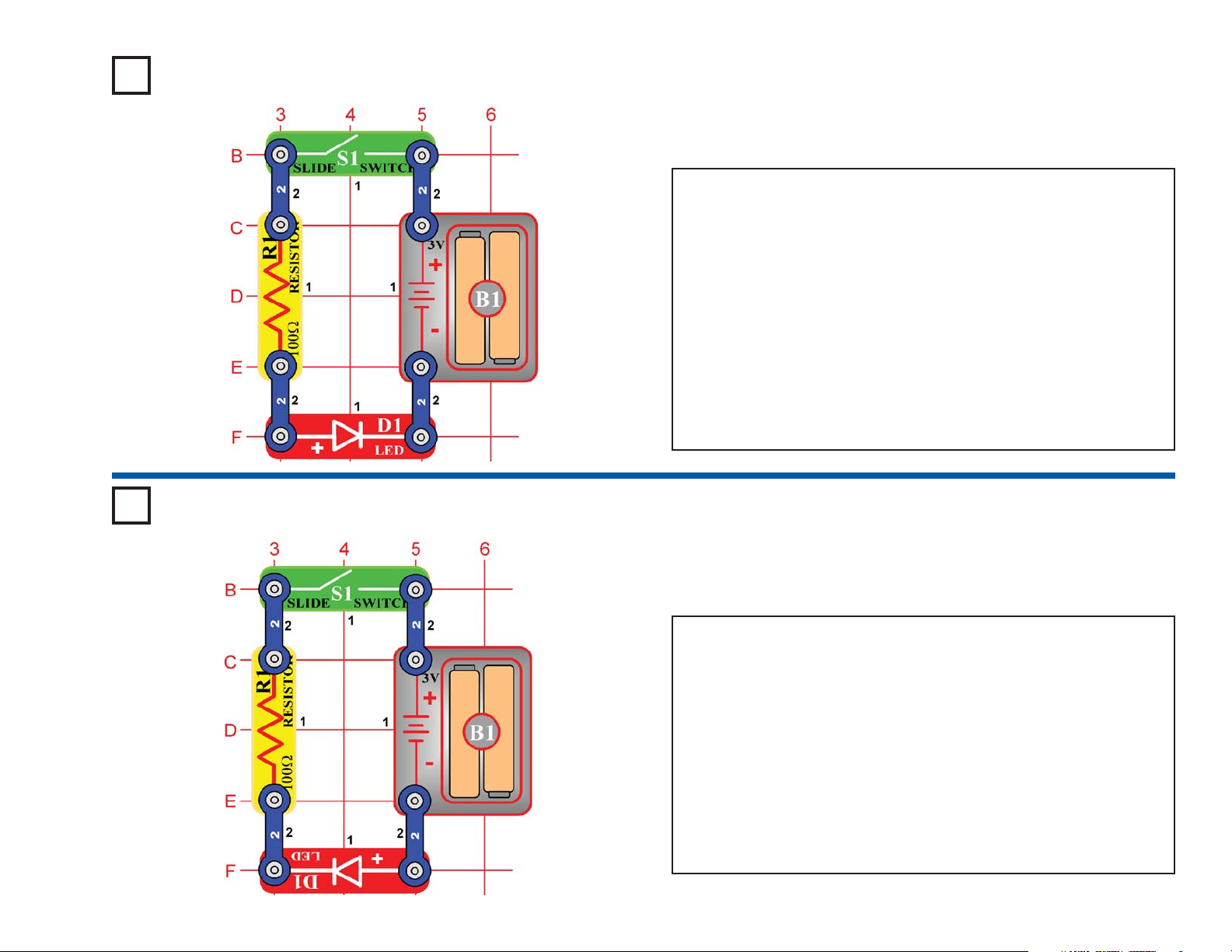
Project #7
OBJECTIVE: To show how a resistor and LED are wired to emit
light.
Build the circuit shown on the left by placing all the parts with a black 1
next to them on the board first. Then, assemble parts marked with a 2.
When you turn on the slide switch (S1), current flows from the batteries
(B1) through the switch, through the resistor (R1), through the LED
(light emitting diode) (D1) and back to the battery. The closed (turned
on) switch completes the circuit. The resistor limits the current and
prevents damage to the LED. NEVER PLACE AN LED DIRECTLY
ACROSS THE BATTERY! If no resistor is in the circuit, the battery may
push enough current through the LED to damage the semiconductor
that is used to produce the light.
LED’s are used in all types of electronic equipment to indicate
conditions and pass information to the user of that equipment.
Can you think of something you use everyday that has an LED in it?
Light Emitting Diode
Project #8
OBJECTIVE: To show how electricity can only pass in one
direction through an LED.
Rebuild the circuit used in project #7, but put the LED (D1) in as shown
on the left.
When you turn on the slide switch (S1), current should flow from the
batteries (B1) through the resistor (R1) and then through the LED.
When current flows through an LED, it lights up. Since the LED is in
backwards, current cannot flow. The LED is like a check valve that lets
current flow in only one direction.
In this project, you changed the direction for current through the LED.
An electronic component that needs to be connected in one direction is
said to have polarity. Other parts like this will be discussed in future
projects. Placing the LED in backwards does not harm it because the
voltage is not large enough to break down this electronic component.
One Direction for LED
Page 20
-19-
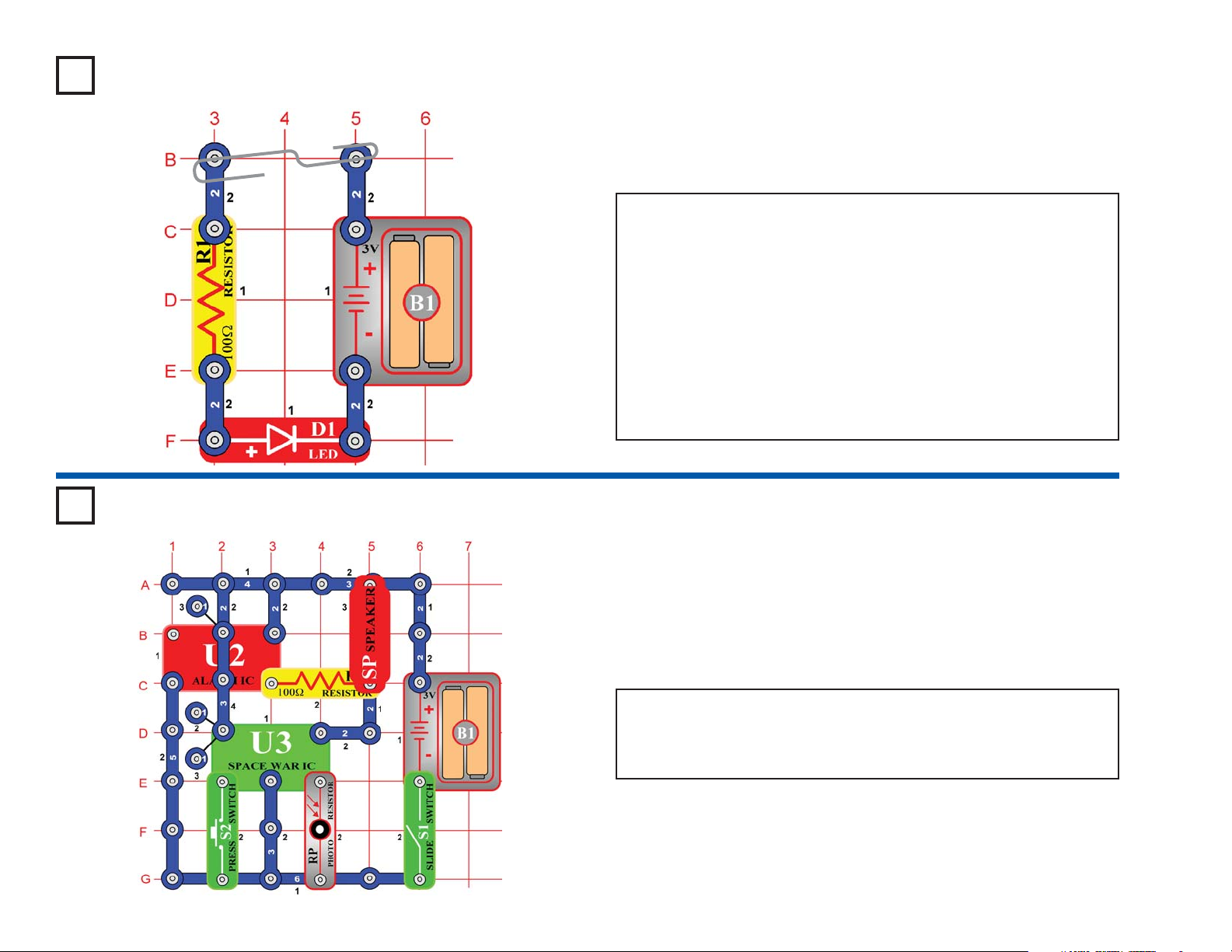
Project #9
OBJECTIVE: To make a circuit that detects the conduction of
electricity in different materials.
Rebuild the circuit from project #7 but leave the on-off switch out as
shown on the left.
When you place a metal paper clip across the terminals as shown in
the picture on the left, current flows from the batteries (B1) through the
resistor (R1), through the LED (D1), and back to the battery. The
paper clip completes the circuit and current flows through the LED.
Place your fingers across the terminals and the LED does not light.
Your body is too high of a resistance to allow enough current to flow to
light the LED. If the voltage, which is electrical pressure, was higher,
current could be pushed through your fingers and the LED would light.
This detector can be used to see if a material like plastic is a good
conductor or a poor conductor.
Conduction Detector
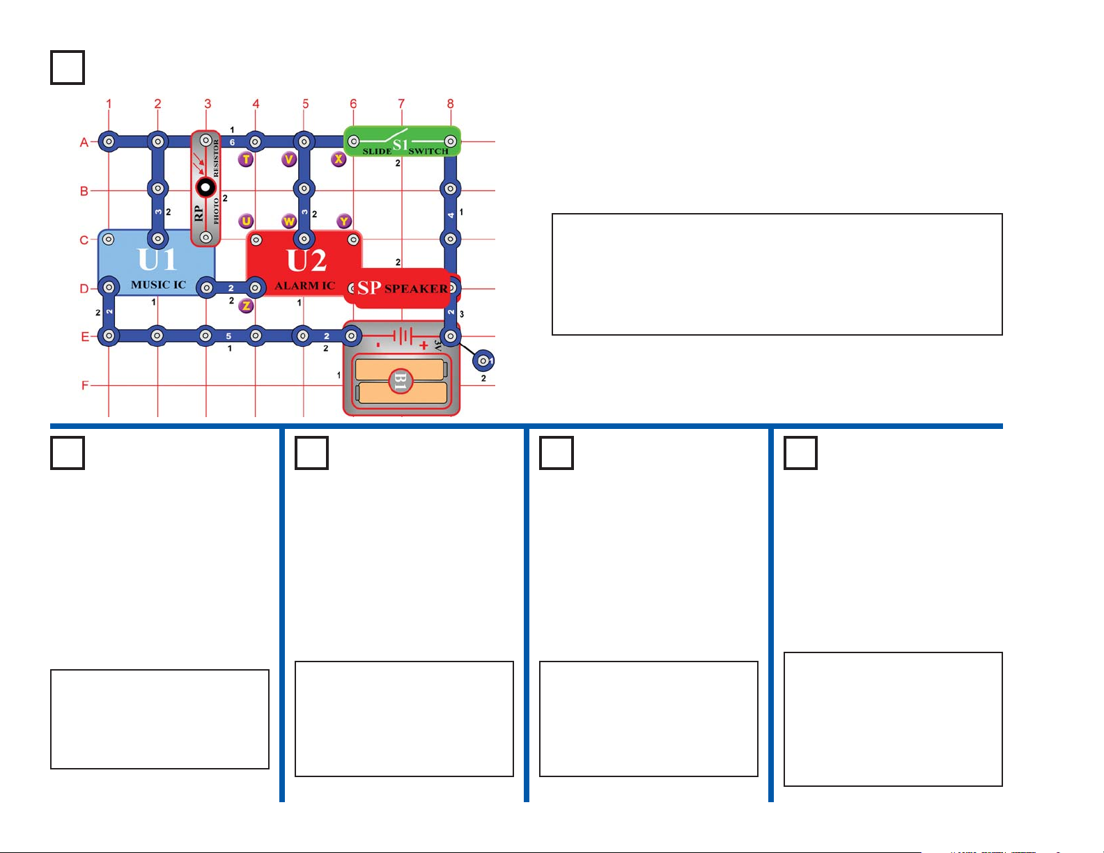
Project #10
OBJECTIVE: To combine the sounds from the space war and
alarm integrated circuits.
Build the circuit shown. Turn it on, press the press switch (S2) several
times, and wave your hand over the photoresistor (RP) to hear all the
sound combinations. You can make the sound from the alarm IC (U2)
louder by replacing the 100Ω resistor (R1) with the 6V lamp (L2).
Space War Alarm Combo
Page 21
-20-
Project #11
OBJECTIVE: To make a circuit that launches the fan blade to
simulate a flying saucer.
Rebuild the circuit from project #2, but reverse the polarity on the motor
(M1) so the negative (–) on the motor goes to the positive (+) on the battery.
When you turn on the slide switch (S1), the motor will slowly increase
in speed. When the motor has reached maximum rotation, turn the
slide switch off. The fan blade should rise and float through the air like
a flying saucer. Be careful not to look directly down on fan blade when
it is spinning.
The air is being blown down through the blade and the motor rotation
locks the fan on the shaft. When the motor is turned off, the blade
unlocks from the shaft and is free to act as a propeller and fly through
the air. If the speed of rotation is too slow, the fan will remain on the
motor shaft because it does not have enough lift to propel it. The motor
will spin faster when both batteries are new.
If the fan doesn’t fly off, then turn the switch on and off several times
rapidly when it is at full speed.
Flying Saucer
Project #12
OBJECTIVE: To show how voltage affects speed of a DC motor
and can decrease the lift of the saucer.
Change the circuit in project #11 by adding the lamp (L2) in series with
the motor (M1) as shown in the diagram on the left.
When you place the lamp in series with any electronic device, it will
draw less current because it adds resistance. In this case, the lamp in
series reduces the current through the motor, and that reduces the top
speed of the motor. Turn on the slide switch (S1) and wait until the fan
reaches maximum speed. Turn the switch off and observe the
difference in the height due to the lamp. In most cases, it may not even
launch.
Decreasing Saucer Lift
!
WARNING: Moving parts. Do not touch the fan or
motor during operation.
!
WARNING: Do not lean over the motor.
!
WARNING: Moving parts. Do not
touch the fan or motor during operation.
!
WARNING: Do not
lean over the motor.
Page 22
-21-
Project #13
OBJECTIVE: To show how switches can increase or decrease
the speed of an electric fan.
Build the circuit shown on the left by placing all the parts with a black
1 next to them on the board first. Then, assemble parts marked with
a 2. Finally, add the 2-snap wires that are marked for level 3.
When you turn on the slide switch (S1), current flows from the
batteries (B1) through the slide switch, motor (M1), the lamp (L2), and
back to the battery. When the press switch (S2) is pressed, the lamp
is shorted and motor speed increases.
The principle of removing resistance to increase motor speeds is only
one way of changing the speed of the motor. Commercial fans do not
use this method because it would produce heat in the resistor and fans
are used to cool circuits by moving air over them. Commercial fans
change the amount of voltage that is applied to the motor using a
transformer or other electronic device.
Two-Speed Fan
OBJECTIVE: To show how a fuse is used to break all current
paths back to the voltage source.
Use the circuit built in project #13.
When you turn on the slide switch (S1), current flows from the
batteries (B1) through the slide switch, the lamp (L2), motor (M1), and
back to the battery. Pretend the 2-snap wire marked fuse in the
drawing on the left is a device that will open the circuit if too much
current is taken from the battery. When press switch (S2) is pressed,
the lamp is shorted and motor speed increases due to an increase in
current to the motor. While still holding the press switch down, remove
the 2-snap wire marked fuse and notice how everything stops. Until
the fuse is replaced, the open circuit path protects the electronic parts.
If fuses did not exist, many parts could get hot and even start fires.
Replace the 2-snap wire and the circuit should return to normal.
Many electronic products in your home have a fuse that will open when
too much current is drawn. Can you name some?
The FuseProject #14
!
WARNING: Moving
parts. Do not touch
the fan or motor during
operation.
!
WARNING: Moving
parts. Do not touch
the fan or motor during
operation.
Page 23
-22-
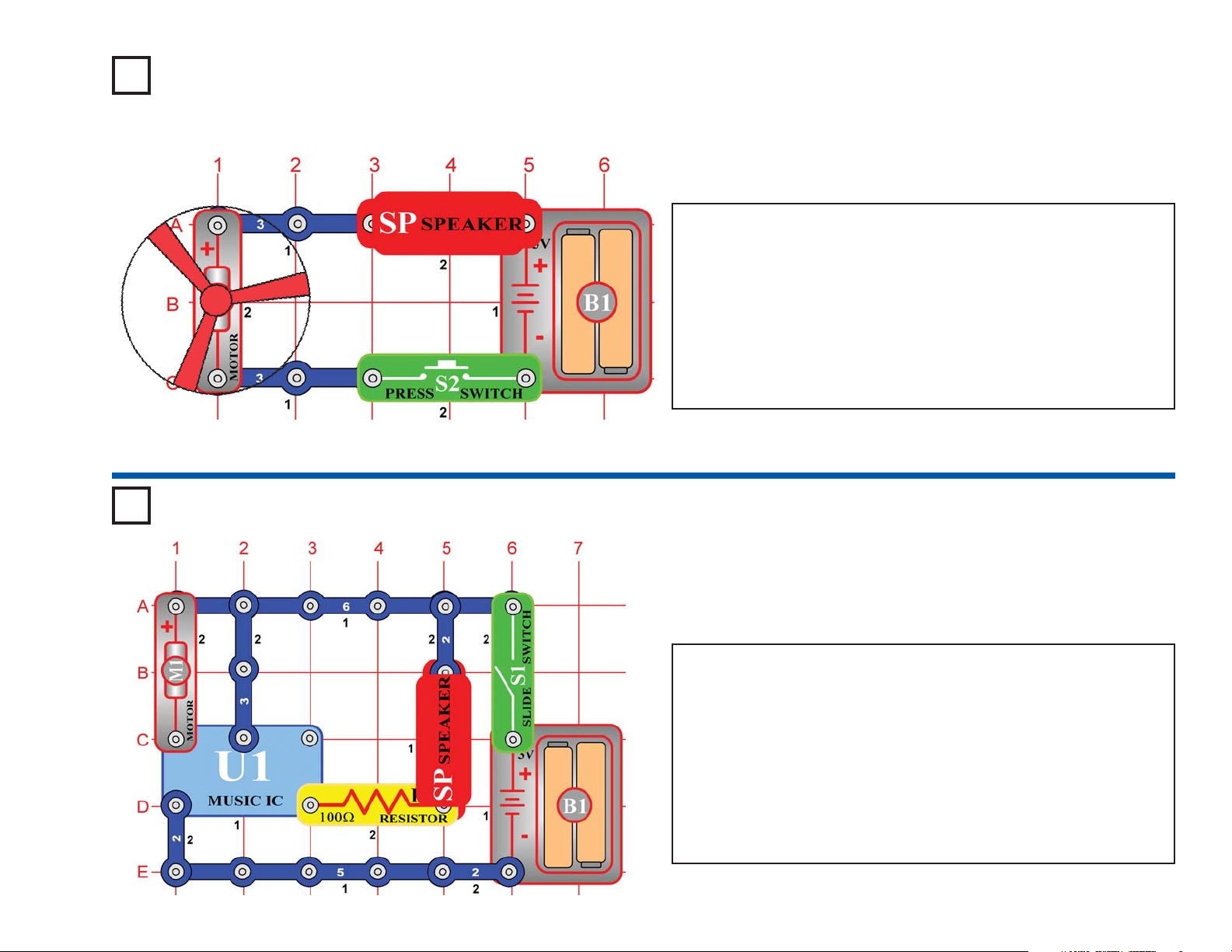
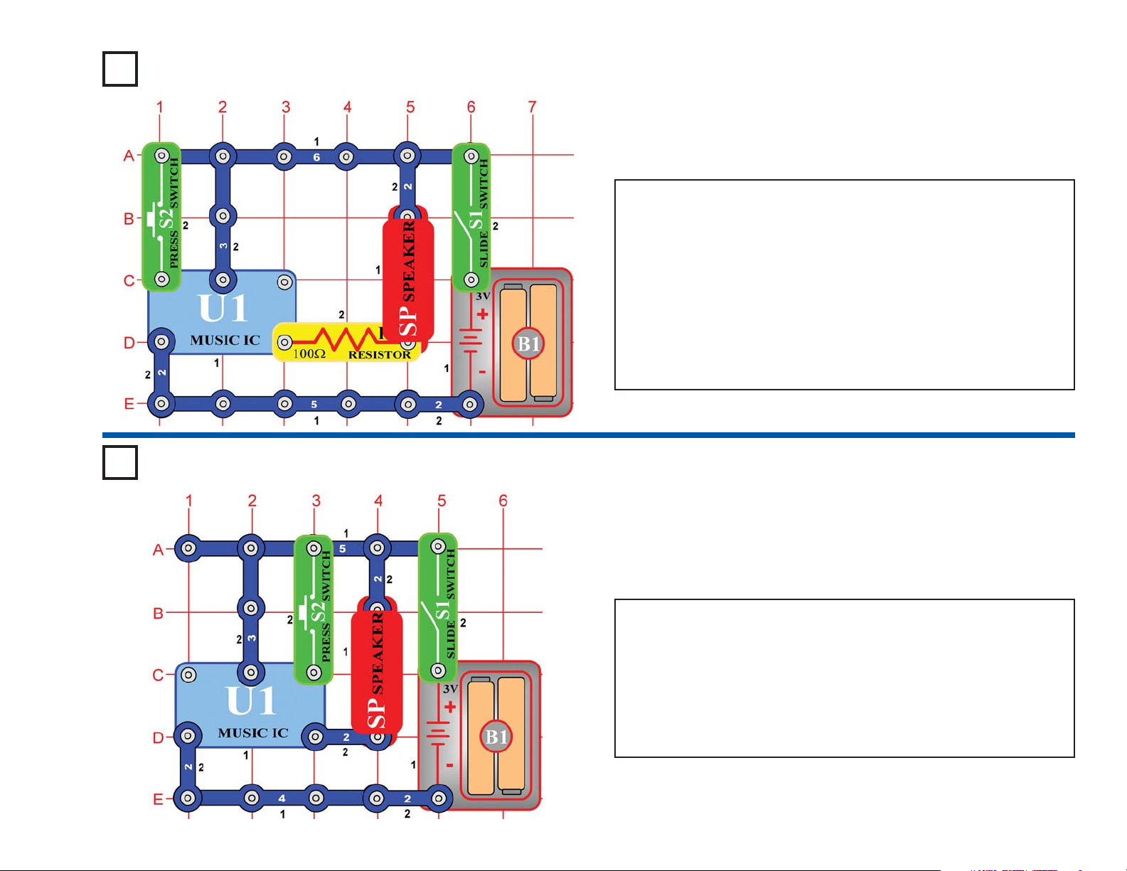
Project #15
OBJECTIVE: To show how an integrated circuit can be used as
a musical doorbell.
Build the circuit shown on the left. When you turn on the slide switch
(S1), the music integrated circuit (U1) may start playing one song then
stop. Each time you press the press switch “doorbell button” (S2) the
song will play again and stop. Even if you let go of the press switch,
the integrated circuit keeps the song playing until it has reached the
end of the song.
Musical integrated circuits are used to entertain young children in
many of the toys and chairs made to hold infants. If the music is
replaced with words, the child can also learn while they are
entertained. Because of great advances in miniaturization, many
songs are stored in a circuit no bigger than a pinhead.
Musical Doorbell
Project #16
OBJECTIVE: To show how integrated circuits can also create
loud alarm sounds in case of emergencies.
Modify the circuit used in project #15 to look like the one shown on the
left.
When you turn on the slide switch (S1), the music integrated circuit
(U1) may start playing one song then stop. The song will be much
louder than in the previous project because it is now being used as an
alarm. Each time you press the press switch “alarm button” (S2) after
the song stops playing, the song will play again, but only while you
hold the button down.
Momentary Alarm
Page 24
-23-
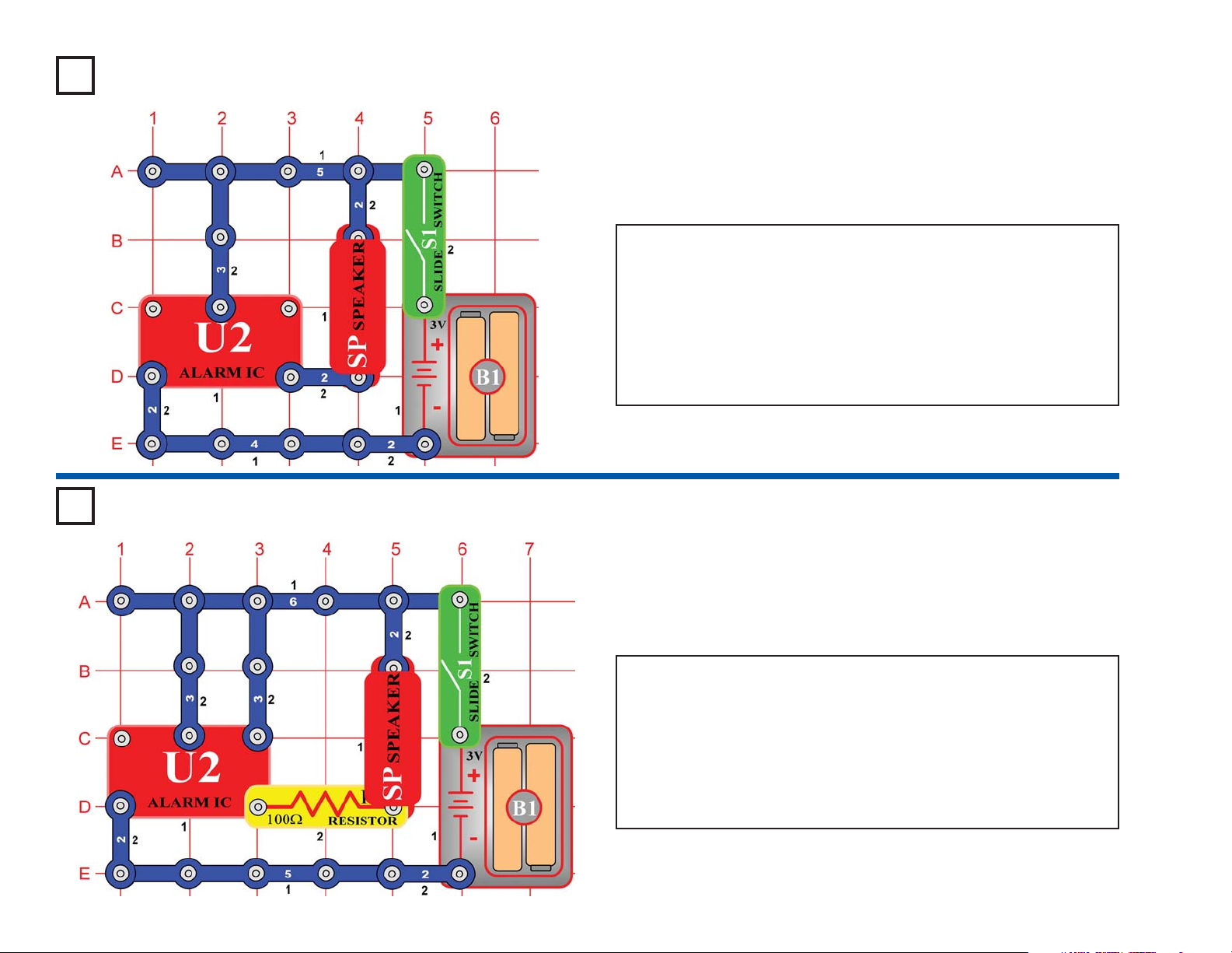
Project #17
OBJECTIVE: To show how an integrated circuit can be used to
make real alarm sounds.
Build the circuit shown on the left by placing all the parts with a black 1
next to them on the board first. Then, assemble parts marked with a 2.
When you turn on the slide switch (S1), the integrated circuit (U2)
should start sounding a very loud alarm sound. This integrated circuit
is designed to sweep through all the frequencies so even hard of
hearing people can be warned by the alarm.
If the alarm sound was passed through an amplifier and installed into
a police car, it would also serve as a good police siren.
Alarm Circuit
Project #18
OBJECTIVE: To show how integrated circuits sound can easily
be changed to exciting space war sounds.
Build the circuit shown on the left by placing all the parts with a black
1 next to them on the board first. Then, assemble parts marked with
a 2.
When you turn on the slide switch (S1), the integrated circuit (U2)
should start sounding a laser gun sound. This integrated circuit is
designed to produce different sounds that can easily be changed. You
can even switch the sound on and off quickly to add sound effects to
your games or recordings.
Laser Gun
Page 25
-24-
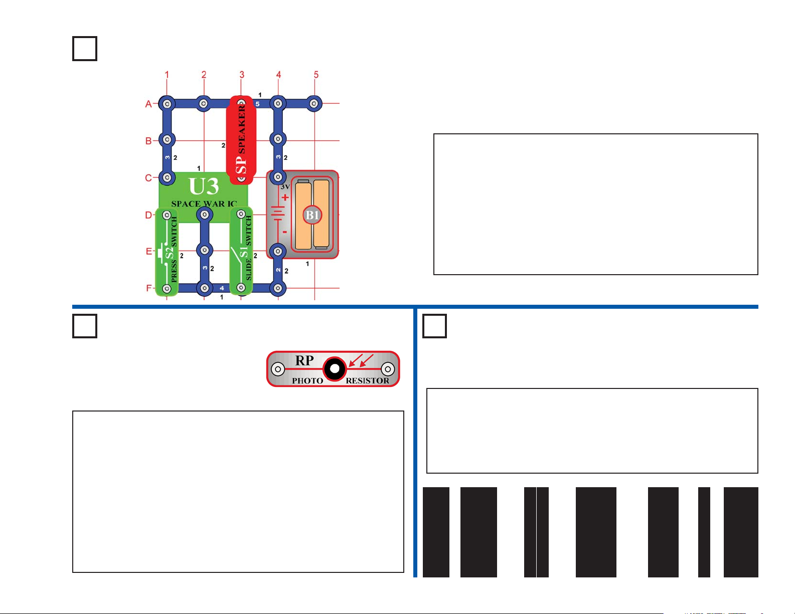
Project #19
OBJECTIVE: To introduce you to the space war integrated
circuit and the sounds it can make.
Build the circuit shown on the left, which uses the space war integrated
circuit (U3). Activate it by turning on the slide switch (S1) or pressing
the press switch (S2), do both several times and in combination. You
will hear an exciting range of sounds, as if a space war is raging!
Like the other integrated circuits, the space war IC is a superminiaturized electronic circuit that can play a variety of cool sounds
stored in it by using just a few extra components.
In movie studios, technicians are paid to insert these sounds at the
precise instant a gun is fired. Try making your sound occur at the
same time an object hits the floor. It is not as easy as it sounds.
Space War
Project #20 Light Switch
OBJECTIVE: To show how light
can control a circuit using a
photoresistor.
Use the circuit from project #19 above, but replace the slide switch (S1)
with the photoresistor (RP). The circuit immediately makes noise. Try
turning it off. If you experiment, then you can see that the only ways to
turn it off are to cover the photoresistor, or to turn off the lights in the
room (if the room is dark). Since light is used to turn on the circuit, you
might say it is a “light switch”.
The photoresistor contains material that changes its resistance when it
is exposed to light, as it gets more light, the resistance of the
photoresistor decreases. Parts like this are used in a number of ways
that affect our lives. For example, you may have streetlights in your
neighborhood that turn on when it starts getting dark and turn off in the
morning.
Project #21 Paper Space War
OBJECTIVE: To give a more dramatic demonstration of using the
photoresistor.
Use the same circuit as for project #20. Find a piece of white paper that
has a lot of large black or dark areas on it, and slowly slide it over the
photosensitive resistor. You should hear the sound pattern constantly
changing, as the white and dark areas of the paper control the light to
the photosensitive resistance. You can also try the pattern below or
something similar to it:
Page 26
-25-
Project #22
OBJECTIVE: To build a police siren that is controlled by light.
Build the circuit shown on the left by placing all the parts with a black
1 next to them on the board first. Then, assemble parts marked with
a 2. Finally, insert the parts with a 3 last on level 3.
Cover the photoresistor (RP) and turn on the slide switch (S1). A
police siren with music is heard for a while and stops, then you can
control it by covering or uncovering the photoresistor.
Light Police Siren
Project #23
More Loud
Sounds
OBJECTIVE: To show
variations of the circuit in
project #22.
Project #24
More Loud
Sounds (II)
OBJECTIVE: To show
variations of the circuit in
project #22.
OBJECTIVE: To show
variations of the circuit in
project #22.
Project #26
More Loud
Sounds (IV)
OBJECTIVE: To show
variations of the circuit in
project #22.
Project #25
More Loud
Sounds (III)
Modify the project #22 by
connecting points X & Y. The
circuit works the same way but
now it sounds like a machine
gun with music.
Now remove the connection
between X & Y and then make a
connection between T & U. The
circuit works the same way but
now it sounds like a fire engine
with music.
Now remove the connection
between T & U and then make a
connection between U & Z. The
circuit works the same way but
now it sounds like an ambulance
with music.
Now remove the connections
between U & Z and between V &
W, then make a connection
between T & U. The circuit
works the same way but now it
sounds like a familiar song but
with static.
Page 27
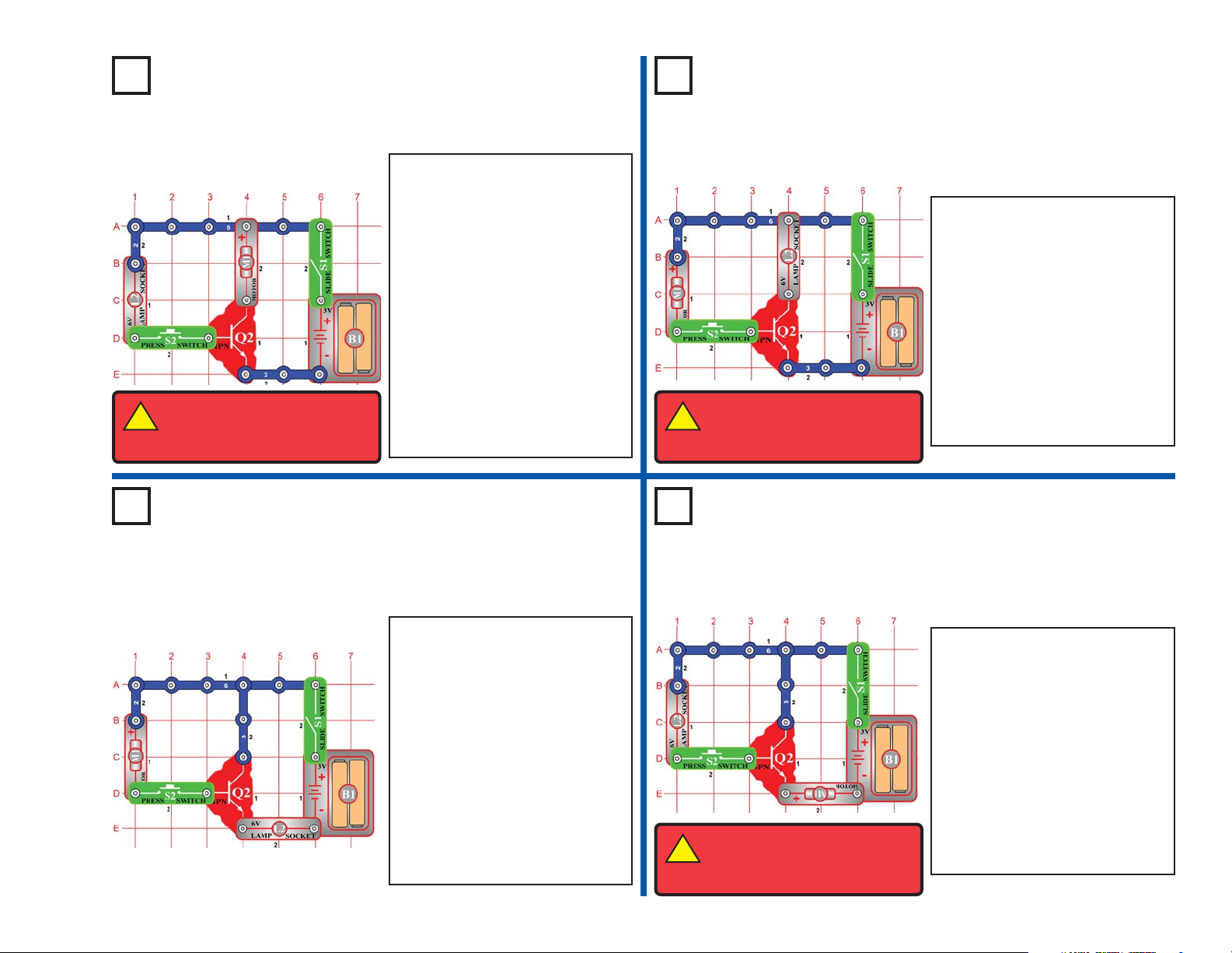
-26-
Project #27
The Transistor
OBJECTIVE: To compare
transistor circuits.
Project #28
The Transistor (II)
Place the fan on the motor (M1)
and turn on the slide switch (S1)
- nothing happens. Press the
press switch (S2), the lamp (L2)
lights dimly and the motor spins.
The lamp will be brighter if you
remove the fan from the motor.
The NPN transistor (Q2) uses
the lamp current to control the
motor current. A small current
through the lamp branch creates
a large current through the motor
branch. They combine in the
transistor and leave through the
3-snap branch.
OBJECTIVE: To compare transistor circuits.
Compare this circuit to project
#27. It works the same way, but
the lamp (L2) is brighter here and
the motor (M1) is slower.
This time the NPN transistor (Q2)
uses the motor current to control
the lamp current. A current
through the motor branch creates
a larger current through the lamp
branch. They combine in the
transistor and leave through the
3-snap branch.
Project #29
The Transistor (III)
OBJECTIVE: To compare transistor circuits.
Project #30
The Transistor (IV)
Compare this circuit to project
#28. It works in a similar way,
but the motor (M1) does not spin
even though the lamp (L2) is
bright. But the lamp is not as
bright here as in project #28.
The currents in the motor branch
and 3-snap branch are combined
into the lamp branch. Since the
3-snap has no resistance, the
current through its branch will be
much larger than the motor
branch current.
OBJECTIVE: To compare transistor circuits.
Compare this circuit to project
#29. It works in a similar way,
the lamp (L2) is off but the motor
(M1) spins. But the motor does
not spin as fast as in project #27.
The currents in the lamp branch
and 3-snap branch are combined
into the motor branch. Since the
3-snap has no resistance, the
current through its branch will be
much larger than the lamp
branch current.
!
WARNING: Moving parts.
Do not touch the fan or motor
during operation.
!
WARNING: Moving parts.
Do not touch the fan or motor
during operation.
!
WARNING: Moving parts.
Do not touch the fan or motor
during operation.
Page 28
-27-
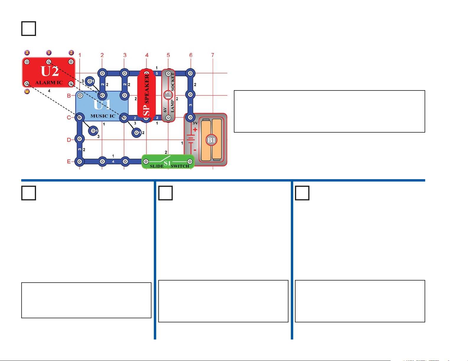
Project #31
OBJECTIVE: To connect two sound IC’s together.
In the circuit, the outputs from the alarm and music IC’s are connected
together. Build the circuit shown and then place the alarm IC (U2)
directly over the music IC (U1), resting on two 1-snaps and a 2-snap.
Turn on the slide switch (S1) and you will hear a siren and music
together while the lamp (L2) varies in brightness.
Sound Mixer
OBJECTIVE: To connect two sound IC’s
together.
OBJECTIVE: To connect two sound IC’s
together.
OBJECTIVE: To connect two sound IC’s
together.
Project #34
Sound Mixer
(IV)
Modify the last circuit by connecting points Y &
Z with a 2-snap (on level 5). The circuit works
the same way but now it sounds like a machine
gun with music.
Project #33
Sound Mixer
(III)
Project #32
Sound Mixer
(II)
Now remove the 2-snap connection between Y
& Z and then make a 2-snap connection
between X & Y (on level 5). The circuit works
the same way but now it sounds like a fire
engine with music.
Now remove the 2-snap connection between X
& Y and then make a 2-snap connection
between W & X (on level 5). The circuit works
the same way but now it sounds like an
ambulance with music.
Page 29
-28-
OBJECTIVE: To build a circuit with
light and sound that change and repeat.
Project #38
Blinking
Double
Flashlight
Build the circuit shown on the left and turn
it on. The lamp (L2) alternates between
being on and off while the speaker (SP)
alternates between two musical tones . . .
like someone is flipping a switch, but at a
very consistent rate. Periodic signals like
this are very important in electronics.
Project #37 Periodic Sounds
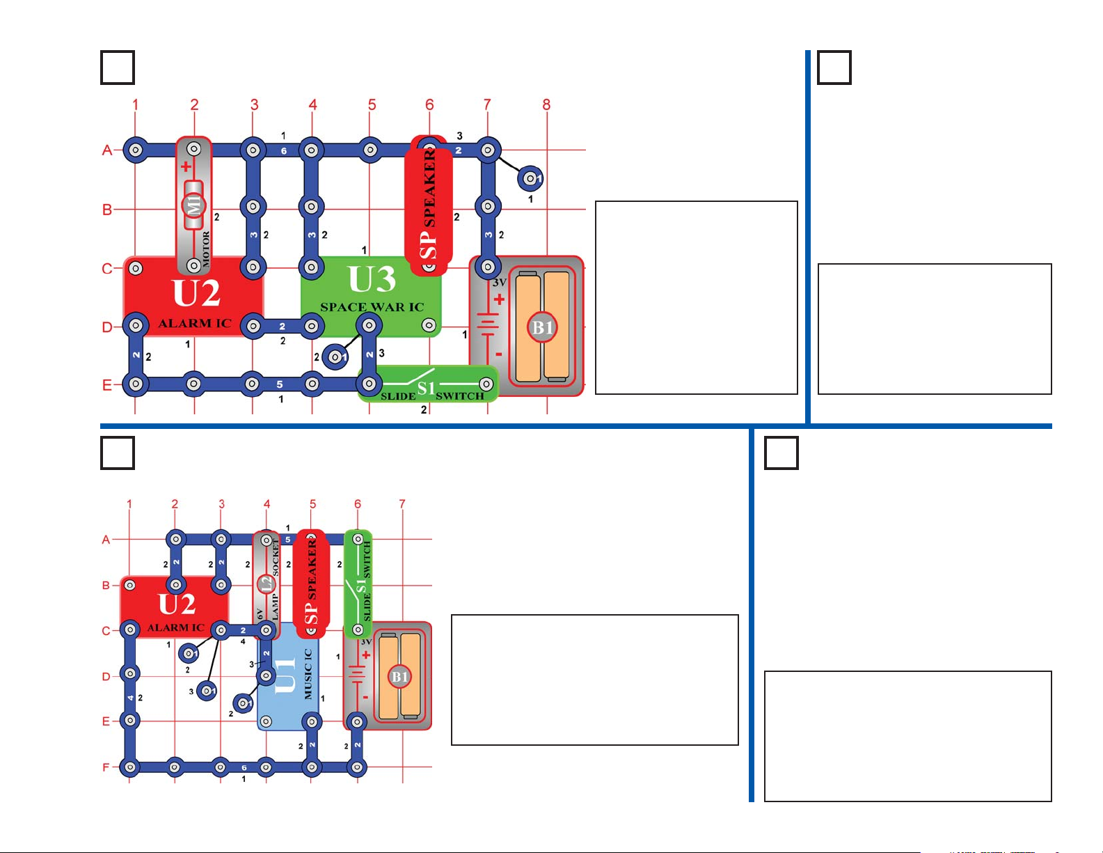
Project #35 Space Battle
OBJECTIVE: To show
another way of using the
space war integrated circuit.
Build the circuit shown on the
left, which is based on the
circuit in the Space War
project #19. Turn on the slide
switch (S1) and you will hear
exciting sounds, as if a space
battle is raging!
The motor (M1) is used here
as a 3-snap wire, and will not
spin.
Project #36
Silent Space
Battle
OBJECTIVE: To show another
way of using the space war part.
OBJECTIVE: To build a circuit with two
lights that alternate.
The preceding circuit is loud and
may bother people around you, so
replace the speaker (SP) with the
LED (D1). Make sure you connect
the LED with the positive (+) side
on A6, not U3. Now you have a
silent space battle.
In the circuit at left, replace the speaker
(SP) with the LED (D1). Make sure you
connect the LED with the positive (+) side
on A5, not U1. The lamp (L2) alternates
between being on and off while the LED
alternates between being dimmer and
brighter.
Page 30
-29-
Project #39
OBJECTIVE: To show how motion can trigger electronic
circuits.
This circuit is controlled by spinning the motor (M1) with your hands.
Turn on the slide switch (S1). A police siren is heard and then stops.
Spin the motor and it will play again. Note, however, that music can be
heard faintly in the background of the siren.
Motor-controlled Sounds
Project #40
More Motor
Sounds
OBJECTIVE: To show how
motion can trigger electronic
circuits.
Project #41
More Motor
Sounds (II)
OBJECTIVE: To show how
motion can trigger electronic
circuits.
OBJECTIVE: To show how
motion can trigger electronic
circuits.
OBJECTIVE: To show how
motion can trigger electronic
circuits.
Project #42
More Motor
Sounds (III)
Project #43
More Motor
Sounds (IV)
Modify the last circuit by
connecting points X & Y. The
circuit works the same way but
now it sounds like a machine
gun.
Now remove the connection
between X & Y and then make a
connection between T & U. The
circuit works the same way but
now it sounds like a fire engine.
Now remove the connection
between T & U and then make a
connection between U & Z. The
circuit works the same way but
now it sounds like an
ambulance.
Now remove the connections
between U & Z and between V &
W, then make a connection
between T & U. The circuit
works the same way but now it
sounds like a familiar song but
with static.
Page 31

-30-
Project #44
OBJECTIVE: To make a circuit that uses light to control the
blinking of another light.
This circuit does not use the noisy speaker it uses a nice quiet LED
(D1). Turn on the slide switch (S1), the LED flickers. Wait a few
seconds, and then cover the photoresistor (RP), and the flicker stops.
The flicker is controlled by the photoresistor; uncover it and the flicker
resumes.
People that are deaf need lights to tell them when a doorbell is ringing.
They also use circuits like this to tell them if an alarm has been
triggered or an oven is ready.
Can you think of other uses?
Light-controlled Flicker
Project #45
OBJECTIVE: To investigate the different sound effects available
from the alarm integrated circuit.
Build the circuit shown on the left.
When you turn on the slide switch
(S1), the integrated circuit (U2) should start sounding an up-down
siren. This is just one more sound effect that this integrated circuit is
designed to produce. Different sounds that can easily be changed are
very important when designing games and toys. Switch the sound on
and off quickly and see if you can create even different effects. This
mode will create many robotic sounds if switched quickly.
More Sound Effects
Page 32

-31-
Project #46
OBJECTIVE: To learn about a device that is used to delay
actions in electronics.
Build the circuit and press the press switch (S2). You see that the LED
(D1) turns off slowly after you release the switch.
This delay in turning off the LED is caused by the 470μF capacitor
(C5). Capacitors can store electricity and are used to delay changes
in voltage. They can block unchanging voltages while passing fastchanging voltages.
Slow Off Switch
Project #47
Transistor Diodes
OBJECTIVE: To learn about transistors.
Project #48
Four Outputs
OBJECTIVE: To learn about transistors.
Turn on the slide switch (S1), the LED
(D1) and lamp (L2) are bright. This is an
unusual circuit which uses the NPN
transistor (Q2) as two connected diodes
to split the current from the batteries (B1)
into the paths with the LED and lamp. If
the LED does not light, you may have
weak batteries in need of replacement.
Transistors use a small current to control
a large current, and have three
connection points (the small current, the
larger current, and the combined
current). But they are actually
constructed using two diodes that are
connected together. These diodes are
similar to your LED (light emitting diode)
except that they don’t emit light.
This circuit has four different types of
output. Do not place the fan on the motor
(M1). Press the press switch (S2) several
times. The LED (D1) and lamp (L2) are
bright, the motor spins, and the speaker
(SP) makes a static sound. If the LED
does not light, you may have weak
batteries that need replacement.
This is an unusual circuit which uses the
NPN transistor (Q2) as two connected
diodes, to split the current from the
batteries (B1) into the paths with the LED
and lamp.
!
WARNING: Moving parts. Do
not touch the fan or motor during
operation.
Page 33

-32-
Project #49
OBJECTIVE: To learn about one device that is used to delay
actions in electronics.
Auto-Off Night Light
Project #50
OBJECTIVE: To learn about one device that is used to delay
actions in electronics.
Cover the photoresistor (RP) and turn on the slide switch (S1). The
LED (D1) is bright, but it will very slowly get dimmer and dimmer as the
470μF capacitor (C5) charges up. If you turn the slide switch off and
back on after the light goes out, it will NOT come on again. Press the
press switch (S2) to discharge the capacitor and reset the circuit.
If you uncover the photoresistor and to let light shine on it, then the
LED will get dark quickly. The photoresistor has much lower
resistance with light on it, and this lower resistance allows the
capacitor to charge up faster.
Auto-Off Night Light (II)
When you turn on the slide switch (S1) the first time, the light will come
on and very slowly get dimmer and dimmer. If you turn the slide switch
off and back on after the light goes out, it will NOT come on again. The
470μF capacitor (C5) has charged up and the NPN transistor amplifier
(Q2) can get no current at its input to turn it on. To discharge the
capacitor (C5) and reset the circuit, press and release the press switch
(S2).
This circuit would make a good night light. It would allow you to get
into bed, and then it would go out. No further current is taken from the
battery so it will not drain the batteries even if left on all night.
Page 34

-33-
Project #51
OBJECTIVE: To detect if a mirror is present.
Build the circuit on the left. Place it where there won’t be any room
light hitting the photoresistor (RP) (such as in a dark room or under a
table), and then turn it on. The 6V lamp (L2) will be bright but there
should be little or no sound.
Take a small mirror and hold it over the lamp and photoresistor. You
should hear sound now. You have a reflection detector! The more light
that gets reflected like this, the louder the sound. You can try holding
the mirror at different angles and distances and see how the sound
changes. You can also hold a white piece of paper over them, since
white surfaces reflect light.
Reflection Detector
Project #52
OBJECTIVE: To detect a mirror.
Let’s modify the reflection detector circuit so that it is not so loud and
annoying. We’ll also put a lamp on it that can be seen in a noisy room.
Build the circuit on the left. Place it somewhere where there won’t be
any room light hitting the photoresistor (RP) (such as in a dark room
or under a table), and then turn it on. The 6V lamp (L2) will be bright
but there should be little or no sound.
Take a small mirror and hold it over the lamp and photoresistor. You
should hear sound now as the mirror reflects light from the lamp onto
the photoresistor. The more light that gets reflected like this, the louder
the sound. You can also hold a white piece of paper over the circuit,
since white surfaces reflect light.
Quieter Reflection Detector
Page 35

-34-
Project #53
OBJECTIVE: To build the circuit used in a toy laser gun with
flashing laser light and trigger.
When you press the press switch (S2), the integrated circuit (U2)
should start sounding a very loud laser gun sound. The red LED (D1)
will flash simulating a burst of laser light. You can shoot long repeating
laser burst, or short zaps by tapping the trigger switch.
Flashing Laser Light
with Sound
Project #54
OBJECTIVE: To build a circuit using the space war IC to make
exciting sounds.
Build the circuit shown on the left, which uses the space war integrated
circuit (U3).
Turn the slide switch (S1) on and the speaker (SP) makes exciting
sounds. The output of the IC can control lights, speakers, and other
low power devices.
You may replace the speaker with the 6V lamp (L2), and the bulb will
flicker. You can also use the LED (D1) in place of the lamp (position it
with the “+” side towards the 6-snap).
Space War Flicker
Page 36

-35-
Project #55
OBJECTIVE: To build an electronic spinner.
Spinning Rings
!
WARNING: Moving parts. Do not touch the fan or
motor during operation.
!
WARNING: Moving parts. Do not touch the fan or
motor during operation.
Setup: Cut out the disc on page #49 that looks like the one shown
here. Using Scotch tape, attach the disc with the printed side up on
the top of the fan blade. Place the blade on the motor (M1) as shown
on the left and below.
When the press switch (S2) is pressed, the arcs will turn into colored
rings with a black background. Notice how the color drops in
brightness when it is stretched to make a complete circle.
Project #56
OBJECTIVE: To use the spinner to see strobe effect due to 60
cycles.
Use the circuit from project #55.
Setup: Place the spinning rings under a fluorescent light that runs on
normal house current. Start the disc spinning and release the press
switch (S2). As the speed changes you will notice the white lines first
seem to move in one direction then they start moving in another
direction. This effect is because the lights are blinking 60 times a
second and the changing speed of the motor is acting like a strobe
light to catch the motion at certain speeds. To prove this, try the same
test with a flashlight. The light from a flashlight is constant, and if all
other lights are out, you will not see the effect that looks like a
helicopter blade in a movie. Some fluorescent lights use an electronic
ballast and they also produce a constant light.
Strobe the House Lights
Page 37

-36-
Project #57
OBJECTIVE: Build an electronic game for racing.
Race Game
Project #58
OBJECTIVE: To show that motors and lamps may sometimes be
used as ordinary conductors.
Turn on the slide switch (S1) and press the press switch (S2), you hear
a machine gun sound (with music in the background). Thoroughly
cover the photoresistor (RP) with your hand and the sound becomes
a siren. After a while the sound will stop. Press the press switch and
it resumes.
Note that the LED (D1) lights, but the lamp (L2) does not light, and the
motor (M1) does not spin. Electricity is flowing through the lamp and
motor, but not enough to turn them on. So in this circuit they are acting
like 3-snap wires.
Using Parts as
Conductors
!
WARNING: Moving
parts. Do not touch
the fan or motor during
operation.
Cut this shape from page 128 in this
manual and tape it to the speaker.
Modify project #56 by adding the pointer as shown on the left. The paper
should be cut from page 128 and taped high enough on the speaker (SP) so
the pointer will stick over the fan with paper. Bend the pointer at a right angle
as shown on the left.
Setup: Cut out the grid with four (4) colors from page 128 and place it under
the base as shown on the left. Each player picks a color (or two colors if only
2 people are playing) and places a single snap on row G. The purple player
in column 1, the blue player in column 2, the green player in column 3, and the
yellow player in column 4. Spin the wheel by pressing the press switch (S2).
The first single color wedge that the pointer points to is the first player to start.
The Play: Each player gets a turn to press the press switch. They release the
press switch, and when the pointer points to a wedge, the players that match
the colors on the wedge get to move up one space. If a liner comes up like
the one shown on the left, then the players on each side of the line get to move
up two (2) spaces. The first player to reach the top row (A) wins. If two players
reach the top row at the same time, they must both drop down to row “D” and
play continues.
Page 38

-37-
Project #59
OBJECTIVE: To produce circular artistic drawings.
Rebuild the simple motor connection as shown on the left. This is the same setup as project #57.
Setup: Cut out a circular piece of thin cardboard from the back of an old spiral notebook or note pad.
Use the fan blade as a guide. Place the fan on the cardboard and trace around it with a pencil or pen.
Cut the cardboard out with scissors and tape it to the fan blade. Do the same thing with a piece of white
paper, but tape the paper on top of the cardboard so it can be removed easily later.
Drawing: To make a ring drawing obtain some thin and thick marking pens as drawing tools. Spin the
paper by pressing and holding the press switch (S2) down. Press the marker on the paper to form rings.
To make spiral drawings, release the press switch, and as the motor (M1) approaches a slow speed,
move the marker from the inside outward quickly.
Change the colors often and avoid using too much black to get hypnotic effects. Another method is to make
colorful shapes on the disc then spin the disc and watch them blend into each other. When certain speeds
are reached under fluorescent lights without electronic ballasts, the strobe principle shown in another project
will produce strange effects and backward movement. Make a wheel with different colored spokes to see this
strange effect. Adding more spokes and removing spokes will give different effects at different motor speeds.
Spin Draw
Project #60
OBJECTIVE: To run the motor using the space war IC.
Space War Flicker Motor
Thin Cardboard White Paper
Turn on the slide switch (S1) and the motor (M1) spins (you may need
to give it a push with your finger to get it started). The sounds from the
space war IC (U3) are used to drive the motor. Because the motor
uses magnets and a coil of wire similar to a speaker, you may even
hear the space war sounds coming faintly from the motor.
Page 39

-38-
Project #61
OBJECTIVE: To learn about the speaker.
Speaker Static
Project #62
Parallel Resistors
OBJECTIVE: To learn about resistors.
Project #63
Series Resistors
Turn on either or both switches
(S1 & S2) and compare the LED
(D1) brightness.
This circuit has the 100Ω
resistor (R1) and 1KΩ resistor
(R2) arranged in parallel. You
can see that the smaller 100Ω
resistor controls the brightness
in this arrangement.
Turn on either or both switches
(S1 & S2) and compare the LED
(D1) brightness.
This circuit has the 100Ω
resistor (R1), the 1KΩ resistor
(R2), and the photoresistor (RP)
arranged in series. You can see
that the larger photoresistor
controls the brightness in this
arrangement (the resistance of
the photoresistor will be much
higher than the others, unless
the light is very bright).
OBJECTIVE: To learn about resistors.
Turn the slide switch (S1) on and off several times. You hear static
from the speaker (SP) when you first turn on the switch, but hear
nothing after it is left on.
The speaker uses electromagnetism to create changes in air pressure,
which your ears feel and interpret as sound. Think of the speaker as
creating pressure waves in the air just like waves in a pool. You only
see waves in the pool when you disturb the water, so the speaker only
makes sound when the voltage changes.
Page 40

-39-
Project #64
OBJECTIVE: To compare transistor circuits.
Place the fan on the motor (M1) and turn on the slide switch (S1), then
compare this circuit to project #27. Press the press switch (S2), the
lamp (L2) doesn’t light now, but the motor still spins.
The lamp is dark because the 100Ω resistor (R1) limits the current
through it. The NPN transistor (Q2) uses the small lamp current to
create a large current that spins the motor.
Now replace the 100Ω resistor (R1) with the larger 1KΩ resistor (R2).
The motor spins more slowly now, because the transistor cannot
create as large of a motor current from such a small controlling
current.
The Transistor (V)
Project #65
The Transistor (VI)
Project #66
The Transistor (VII)
Compare this circuit to project #28. Press
the press switch (S2), the motor (M1) doesn’t
spin now, but the lamp (L2) still lights.
The motor doesn’t spin because the 100Ω
resistor (R1) limits the current through it.
The NPN transistor (Q2) uses the small
motor current to create a large current that
lights the lamp.
Now replace the 100Ω resistor (R1) with the
larger 1KΩ resistor (R2). The lamp is only
slightly less bright even though the motor
current is much lower.
Now place the 100Ω resistor back in the
circuit and replace the press switch (S2) with
the photoresistor (RP). A bright light on the
photoresistor will turn the lamp on. But if the
light is dim then the photoresistor has high
resistance, so little current flows through the
transistor and the lamp is off.
OBJECTIVE: To compare transistor circuits. OBJECTIVE: To compare transistor circuits.
!
WARNING: Moving parts. Do not touch the fan or
motor during operation.
!
WARNING: Moving
parts. Do not touch
the fan or motor during
operation.
!
WARNING: Moving
parts. Do not touch
the fan or motor during
operation.
Compare this circuit to project #64. It uses
the photoresistor (RP) to control the current
to the NPN transistor (Q2), instead of the
press switch (S2). You can adjust the speed
of the motor (M1) by changing how much light
shines on the photoresistor.
The lamp (L2) is dark because the
photoresistor limits the current through it. The
NPN transistor uses the small lamp current to
create a large current that spins the motor.
If you tried to control the motor speed by
placing the photoresistor in series with the
motor, the motor would not spin because the
photoresistor would limit the current. But the
photoresistor can control the motor speed
with help from the transistor. You may need
to shine a light on the photoresistor if the
motor does not spin.
Page 41

-40-
Project #68
OBJECTIVE: To combine the sounds from the space war and
music integrated circuits.
Build the circuit shown. Turn it on, press the press switch (S2) several
times, and wave your hand over the photoresistor (RP) to hear all the
sound combinations. You can make the sound from the music IC (U1)
louder by replacing the 100Ω resistor (R1) with the 6V lamp (L2).
Space War Music Combo
Project #67
OBJECTIVE: To convert a changing voltage into a constant
voltage.
Simple Rectifier
Turn on the slide switch (S1) and the LED (D1) lights; it will not be very bright
so turn off the room lights or hold your fingers around it to see it better. Press
the press switch (S2) several times slowly; the LED and lamp (L2) go on and off.
Press the press switch many times quickly - the lamp still goes on and off but
the LED stays on. Next, remove the 470μF capacitor (C5) from the circuit - the
LED goes on and off now. Why?
Pressing the switch quickly simulates a changing voltage, which turns the LED
on and off. The 470μF capacitor can store electricity, and it combines with the
NPN transistor (Q2) to simulate a rectifier. This rectifier converts the changing
voltage at the press switch into a constant voltage, which keeps the LED on.
The electricity supplied to your home by your electric company is actually a
changing voltage. Many electronic products use rectifier circuits to convert this
into a constant voltage like a battery provides.
You can replace the 1KΩ resistor with the 100Ω resistor (R1). This makes the
LED a little brighter but you have to press the switch faster to keep it on,
because the lower resistance drains the capacitor faster.
Page 42

-41-
Project #69
OBJECTIVE: To combine effects from the space war and alarm
integrated circuits.
Build the circuit shown on the left and turn on the slide switch (S1).
Press and hold the press switch (S2) to make the lamp (L2) brighter.
Space War Siren
Project #70
OBJECTIVE: To learn about one device that is used to delay
actions in electronics.
Sunrise Light
Cover the photoresistor (RP) and turn on the slide switch (S1). The
LED (D1) is off, but if you wait a long time then it will eventually light
up. Uncover the photoresistor and the LED will light up in just a few
seconds. Press the press switch (S2) and reset the circuit.
The resistance of the photoresistor controls how long it takes to
charge up the 470μF capacitor (C5). Once the capacitor is charged,
current can flow into the NPN transistor (Q2) and turn on the LED.
Pressing the press switch discharges the capacitor.
Page 43

-42-
Project #71
OBJECTIVE: To turn a lamp on and off using light.
Light-controlled Lamp
Project #72
OBJECTIVE: To turn a lamp on and off using the voltage
generated when a motor rotates.
Motor-controlled Lamp
Build the circuit on the left. You will find that the lamp (L2) is on
when neither the slide switch (S1) NOR the press switch (S2) are
on. This is referred to as an NOR gate in electronics and is
important in computer logic.
Example: If neither condition X NOR
condition Y are true, then
execute instruction Z.
Project #73
OBJECTIVE: To build a NOR gate.
Light NOR Gate
Cover the unit, turn the slide switch (S1) on, and notice that the lamp (L2) is off
after a few seconds. Place the unit near a light and the lamp turns on. Cover
the photoresistor (RP) and place it near the light again. The lamp will not turn
on. The resistance of the photoresistor decreases as the light increases. The
low resistance acts like a wire connecting point C to the positive (+) side of the
battery (B1).
Use the circuit from project #71. Remove the photoresistor (RP) and connect
the motor (M1) across points A & B. Turn the slide switch (S1) on and turn the
shaft of the motor and the lamp (L2) will light. As the motor turns, it produces a
voltage. This is because there is a magnet and a coil inside the motor. When
the axis turns the magnetic field will change and generate a small current in the
coil and a voltage across its terminals. The voltage then activates the music IC
(U1).
Page 44

-43-
Project #74
OBJECTIVE: To control an LED using light.
Cover the unit, turn the slide switch (S1) on, and notice that the LED (D1) is
on for a few seconds and then goes off. Place the unit near a light and the
LED will light. Cover the photoresistor (RP) and place it near the light again.
The LED will not turn on. The resistance of the photoresistor decreases as
the light increases.
Light-controlled LED
Project #75
OBJECTIVE: To control an LED using a motor.
Use the circuit from project #74. Connect the motor (M1) across points A1
and C1 on the base grid, then remove the photoresistor (RP). Turn the slide
switch (S1) on and turn the shaft of the motor and the LED (D1) will light. As
the motor turns, it produce a voltage. There is a magnet and a coil inside the
motor. When the axis turns the magnetic field will change and generate a
small current across its terminals. The voltage then activates the music IC
(U1).
Motor-controlled
Time Delay LED
Place the fan on the motor (M1) and turn on the slide switch (S1).
The motor spins briefly as the 470μF capacitor (C5) charges up.
Turn off the slide switch and press the press switch (S2) to
discharge the capacitor and reset the circuit.
You can bypass the capacitor by pressing the press switch while the
slide switch is on. This lets the motor spin at full speed and also
lights the lamp.
Project #76
OBJECTIVE: To learn about a device that is used to delay
actions in electronics.
Capacitor Slow-down
!
WARNING: Moving parts. Do not touch the fan or
motor during operation.
Page 45

-44-
Project #79
OBJECTIVE: Build a circuit that flashes light and plays sounds.
Turn the slide switch (S1) on and the lamp (L2) and LED (D1) starts
flashing. You hear two different tones driving the LED and lamp. IC’s
can be connected to control many different devices at the same time.
Flash & Tone
Project #77
Space War Flicker LED
OBJECTIVE: To
flash an LED
using the space
war IC.
Project #78
Human Space War
OBJECTIVE: To use your body
to control the space war IC.
Wet your fingers with some water
or saliva and touch them across
points A and B several times to
hear some space war sounds.
Press the press switch (S2) to
hear more sounds at the same
time.
This circuit uses your body to
conduct electricity and turn on the
circuit. Wetting your fingers
improves the connection between
the metal and your finger.
Build the circuit
shown on the left.
The circuit uses
the alarm IC (U2)
and space war IC
(U3) to flash the
LED (D1). Turn
the slide switch
(S1) on and the
LED starts
flashing.
Page 46

-45-
Project #80
OBJECTIVE: To show that the fan blade stores energy.
Fan Blade Storing Energy
Place the fan on the motor (M1). Hold down the press switch (S2) for
a few seconds and then watch the LED (D1) as you release the switch.
The LED lights briefly but only after the batteries (B1) are
disconnected from the circuit.
Do you know why the LED lights? It lights because the mechanical
energy stored in the fan blade makes the motor act like a generator.
When the switch is released, this energy creates a brief current
through the LED. If you remove the fan blade from the circuit then the
LED will never light, because the motor shaft alone does not store
enough mechanical energy.
If you reverse the motor direction, then the LED will light the same way,
but the fan may fly off after the LED lights.
!
WARNING: Moving parts. Do not
touch the fan or motor during operation.
!
WARNING: Do not
lean over the motor.
Project #81
Photo Timer Light
OBJECTIVE: To show how
capacitors store energy.
Project #82
NPN Light Control
OBJECTIVE: To compare
transistor circuits.
Turn on the slide switch (S1), the
brightness of the LED (D1)
depends on how much light
shines on the photoresistor (RP).
The resistance drops as more
light shines, allowing more current
to the NPN transistor (Q2).
Press and release the press
switch (S2), then turn on the slide
switch (S1). The LED will light for
a while when there is light on the
photoresistor (RP).
The capacitor (C5) will store
energy until a light shines on the
photo resistor to release the
energy, which activates the NPN
transistor (Q2) and turns on the
LED (D1). Press the press switch
again to recharge the capacitor.
Page 47

-46-
Project #83
OBJECTIVE: To show some new ways of using the alarm IC.
Place the fan on the motor (M1) and turn on the slide switch (S1). The
lamp (L2) lights, the motor spins, and you hear a machine gun sound
(with music in background). Thoroughly cover the photoresistor (RP)
with your hand and the sound becomes a siren. After a while the
sound will stop, hold down the press switch (S2) and the sound
resumes.
Fun with the Alarm IC
Project #84 Musical
Motor
OBJECTIVE: To use the music IC
to control the speed of a fan.
OBJECTIVE: To use the music
IC to control a lamp.
Use the circuit in project #84.
Replace the motor (M1) with the
6V lamp (L2). Now the music IC
(U1) and press switch (S2)
control the lamp brightness.
Place the fan on the motor (M1) and
turn on the slide switch (S1). A song
is heard and the fan spins unevenly.
The fan speed is being controlled by
the music IC (U1).
Now press the press switch (S2) to
control the motor directly, and the
motor spins much faster.
Project #85
Musical
Light
!
WARNING: Moving parts. Do not touch the fan or
motor during operation.
!
WARNING: Moving
parts. Do not touch
the fan or motor during
operation.
Page 48

-47-
Project #86
OBJECTIVE: To combine the sounds from the music and alarm
integrated circuits.
Music Alarm Combo
Project #87 Bomb Sound
OBJECTIVE: Build a circuit that
sounds like a bomb dropping.
OBJECTIVE: Build a circuit
that sounds like bombs
dropping.
Use the circuit from project #87.
Replace the slide switch (S1)
with the motor (M1). Turn the
shaft on the motor and now it
sounds like a bunch of bombs
dropping.
Turn the slide switch (S1) on and you
hear the sound of a bomb dropping
and then exploding. The LED (D1)
lights and then flashes as the bomb
explodes. This is one sound
generated from the space war IC
(U3).
Project #88
Bomb
Sound (II)
Build the circuit shown and then place the alarm IC (U2) directly over
the music IC (U1), resting on the three 1-snaps. Turn on the slide
switch (S1) and you will hear a siren and music together. After a few
seconds, covering the photoresistor (RP) will stop the music (but the
siren continues).
Page 49

Project #90
-48-
Project #89
OBJECTIVE: To connect multiple devices together.
In the circuit, the outputs from the alarm IC (U2) and music IC (U1) are
connected together. Build the circuit shown and then place the alarm
IC directly over the music IC, resting on two 1-snaps and a 2-snap.
Turn on the slide switch (S1) and you will hear a siren and music
together while the lamp (L2) varies in brightness. Press the press
switch (S2) and the fan spins, while the sound may not be as loud. The
fan may rise into the air when you release the switch.
Motor Sounds Combo
OBJECTIVE: To connect multiple devices together.
Motor Sounds Combo (II)
!
WARNING: Moving parts. Do not touch the fan or
motor during operation.
!
WARNING: Do not lean over the motor.
!
WARNING: Moving parts. Do not touch the fan or
motor during operation.
!
WARNING: Do not lean over the motor.
In the circuit, the outputs from the alarm IC (U2) and music IC (U1) are
connected together. Build the circuit shown and then place the alarm
IC directly over the music IC, resting on three 1-snaps. Turn on the
slide switch (S1) and you will hear a siren and music together. Press
the press switch (S2) and the fan spins, while the sound may not be
as loud. The fan may rise into the air when you release the switch.
This circuit is similar to project #89, but the fan will fly a little higher
since the sound circuit no longer drives the lamp (L2) and therefore
uses less battery power.
Page 50

-49-
Project #91
OBJECTIVE: To make a circuit that detects if the fan is on the
motor.
Press the press switch (S2). If the fan is off the motor (M1) (or flies off)
then the LED (L1) will light.
It takes a lot of current to spin the motor when the fan is on it, and the
voltage drops because the batteries (B1) cannot supply enough.
When the fan flies off, the current drops and the voltage rises. The
NPN transistor (Q2, used here as a diode) and 470μF capacitor (C5)
are a detector circuit, which measures the voltage at the motor.
Fan Detector
Project #92
OBJECTIVE: To change siren sounds with a delay.
Turn on the slide switch (S1) and you hear a siren sound.
Now hold down the press switch (S2) until the sound becomes a fire
engine sound. This delay is due to the 10μF capacitor (C3) charging
up and is controlled by the photoresistor (RP). If there is bright light
on the photoresistor, then the delay will be only a few seconds.
Release the press switch and after a while the sound will be a siren
again. The capacitor slowly discharges through the NPN transistor
(Q2).
Slow Siren Changer
!
WARNING: Moving parts. Do not touch the fan or
motor during operation.
!
WARNING: Do not lean over the motor.
Page 51

-50-
Project #93
OBJECTIVE: To learn about a device that is used to delay
actions in electronics.
Capacitor Photo Control
Turn on the slide switch (S1) and press the press switch (S2). If there
is light on the photoresistor (RP), then the LED (D1) will stay on for a
long time after you release the press switch.
The energy stored in the 470μF capacitor (C5) keeps the controlling
current to the NPN transistor (Q2) on even though the press switch
was turned off. If it is dark, the high resistance of the photoresistor
shuts off the current to the transistor.
Project #94
OBJECTIVE: To learn about a device that is used to delay
actions in electronics.
Capacitor Control
Build the circuit and turn on the slide switch (S1). The LED (D1) is
bright but slowly gets dark as the 470μF capacitor (C5) charges up.
The LED will stay dark until you press the press switch (S2), which
discharges the capacitor.
Page 52

-51-
Project #95
OBJECTIVE: To build a circuit that uses a programmed sound IC.
Turn the slide switch (S1) on, a space war sound plays and the LED
(D1) flashes. Press the press switch (S2) to change the sound. If the
photoresistor (RP) is covered, then the sound may stop. Shine light on
it and action resumes. See how many sounds are programmed into
the space war sound IC (U3).
Photo Space War
with LED
Project #96
OBJECTIVE: To convert a changing voltage into a constant
voltage.
Build the circuit and turn on the slide switch (S1). The LED (D1) is
flashing and the speaker (SP) makes a siren sound. Now press the
press switch (S2) to connect the 470μF capacitor (C5) to the circuit.
The LED is brighter and stops flashing.
The signal from the alarm IC (U2) to the speaker is a changing
voltage, which is why the LED was flashing. The 470μF capacitor can
store electricity, and it combines with the NPN transistor (Q2) to make
a rectifier. A rectifier converts a changing voltage into a constant
voltage, so the LED stays on instead of flashing.
Alarm Rectifier
Page 53

-52-
Project #97
OBJECTIVE: To show how light is used to turn an alarm.
The alarm will sound, as long as light is present. Slowly cover the
photoresistor (RP), and the volume goes down. If you turn off the
lights, the alarm will stop. The amount of light changes the resistance
of the photoresistor (less light means more resistance). The
photoresistor and transistor (Q2) act like a dimmer switch, adjusting
the voltage applied to the alarm.
This type of circuit is used in alarm systems to detect light. If an
intruder turned on a light or hit the sensor with a flashlight beam, the
alarm would trigger and probably force the intruder to leave.
Light-controlled Alarm
Project #98 Fading Siren
OBJECTIVE: To produce sound of a siren driving away into the
distance.
Press the press switch (S2), the integrated circuit (U2) should make
the sound of an up-down siren that gets weaker with time. The fading
is produced by the charging of the 470μF capacitor (C5), After it is
charged the current stops and the sound is very weak.
To repeat this effect you must release the press switch, remove the
capacitor, and discharge it by placing it across the snaps on the
bottom bar marked A & B. Then, replace the capacitor and press the
press switch again.
Page 54

-53-
Project #99
OBJECTIVE: To show how switches allow circuits to operate
independently even though they have the same power source.
This circuit combines projects #1, #2, and #6 into one circuit.
Build the circuit and place the fan on the motor (M1). Depending on
which of the switches (S1 or S2) are on, you can turn on either the
lamp (L2) (project #1), the motor (M1) (project #2), or both together
(project #6).
Lamp & Fan
Independent
Project #100
Motor Space Sounds
OBJECTIVE: To build a
circuit that uses a motor to
activate space war sounds.
OBJECTIVE: To build a circuit
that uses a motor to activate a
light diode.
This circuit is loud and may bother
other people around you so
replace the speaker (SP) with the
LED (D1), (position it like in project
#77); the circuit operates in the
same manner.
Project #101
Motor
Space Light
Turn on the slide switch (S1)
and wait for any sounds to
stop then spin the motor
(M1) and the sounds play
again.
Do you know why turning the
motor makes the sound
play? Actually, the DC motor
is also a DC generator and
when you turn it, the motor
generates a voltage that
triggers the sound circuits.
!
WARNING: Moving parts. Do not touch the fan or
motor during operation.
Page 55

-54-
Project #102
OBJECTIVE: To show how light is used to control a street lamp.
Press the press switch (S2) on and set the adjustable resistor (RV) so
the lamp (L2) just lights. Slowly cover the photoresistor (RP) and the
lamp brightens. If you place more light at the photoresistor the light
dims.
This is an automatic street lamp that you can turn on by a certain
darkness and turn off by a certain brightness. This type of circuit is
installed on many outside lights and forces them to turn off and save
electricity. They also come on when needed for safety.
Automatic
Street Lamp
Project 105
Pitch (III)
OBJECTIVE:
See project #103.
Project #103 Pitch
OBJECTIVE: To show how
to change the pitch of a
sound.
Project 104
Pitch (II)
OBJECTIVE:
See project #103.
Replace the 0.1μF capacitor (C2)
with the 0.02μF capacitor (C1)
and replace the 100kΩ resistor
(R5) with the photoresistor (RP).
Wave your hand up and down
over the photoresistor to change
the sound. Changing the light on
the photoresistor changes the
circuit resistance just like varying
the adjustable resistance does.
Note: If you have the adjustable
resistor (RV) set to the right and
light shining on the photoresistor,
then you may not get any sound
because the total resistance is too
low for the circuit to operate.
Build the circuit on the left, turn
it on, and vary the adjustable
resistor (RV). The
frequency
or
pitch
of the sound is changed.
Pitch is the musical profession’s
word for frequency. If you’ve
had music lessons, you may
remember the music scale
using chords such as A3, F5,
and D2 to express the
pitch
of a
sound. Electronics prefers the
term
frequency
, as in when you
adjust the frequency on your
radio.
Since we’ve seen we can
adjust the frequency by
varying the resistance in the
adjustable resistor (RV), are
there other ways to change
frequency? You can also
change frequency by
changing the capacitance of
the circuit. Replace the
0.02μF capacitor (C1) with
the 0.1μF capacitor (C2);
notice how the sound has
changed.
Page 56

-55-
Project #106
OBJECTIVE: To build a circuit that produces multiple space war
sounds.
Turn the slide switch (S1) to the OFF position. Press the
press switch
(S2) down and a space sound will be played. If you hold the
press
switch
down the sound repeats. Press the
press switch
again and a
different sound is played. Keep pressing the
press switch
to hear all
the different sounds.
Next, turn the
slide switch
to ON position. One of the sounds will be
played continuously. Turn the switch off and then back on. A different
sound is played. Keep pressing the press switch to hear all the
different combinations of sounds.
The space war integrated circuit has “logic” built into its circuitry that
allows it to switch between many different sounds.
Space War Sounds
Project #107
OBJECTIVE: To change the sounds of a multiple space war with
light.
Modify the preceding circuit to look like the one shown on the left.
The space war IC (U3) will play a sound continuously. Block the light
to the photoresistor (RP) with your hand. The sound will stop. Remove
your hand and a different sound is played. Wave your hand over the
photoresistor to hear all the different sounds.
Press the press switch (S2) down and now two space war sounds are
played. If you hold the press switch down the sound repeats. Press
the press switch again and a different sound is played. Keep pressing
the press switch to hear all the different combinations of sounds.
Space War Sounds
Controlled By Light
Page 57

-56-
Project #108
OBJECTIVE: To show how resistor values change the frequency
of an oscillator.
Turn on the slide switch (S1), the speaker (SP) will sound and the LED
(D1) will light. Adjust the adjustable resistor (RV) to make different
tones. In an oscillator circuit, changing the values of resistors or
capacitors can vary the output tone or pitch.
Adjustable Tone
Generator
OBJECTIVE: To show how resistor values change the frequency
of an oscillator.
Project #110
Electronic Cicada
OBJECTIVE: To show how capacitors in parallel change the
frequency of an oscillator.
Use the circuit from project #108 shown above, replace the
photoresistor (RP) back to the 10kΩ resistor (R4). Place the 0.1μF
capacitor (C2) on top of the 0.02μF capacitor (C1) . Turn the slide switch
(S1) on and adjust the adjustable resistor (RV). The circuit produces the
sound of the cicada insect. By placing the 0.1μF capacitor on top of the
0.02μF capacitor, the circuit oscillates at a lower frequency. Notice that
the LED (D1) flashes also at the same frequency.
It is possible to pick resistors and capacitors that will make the pitch
higher than humans can hear. Many animals, however, can hear these
tones. For example, a parakeet can hear tones up to 50,000 cycles per
second, but a human can only hear to 20,000.
Use the circuit from project #108 shown above. Replace the 10kΩ (R4)
with the photoresistor (RP). Turn on the slide switch (S1). The speaker
(SP) will sound and the LED (D1) will light. Move your hand up and
down over the photoresistor (RP) and the frequency changes.
Decreasing the light on the photoresistor increases the resistance and
causes the circuit to oscillate at a lower frequency. Notice that the LED
flashes also at the same frequency as the sound.
By using your finger, see if you can vary the sounds enough to make this
circuit sound like an organ playing.
Project #109
Photosensitive
Electronic Organ
Page 58

-57-
Project #111
OBJECTIVE: To transmit Space War sounds to a AM radio.
Place the circuit next to an AM radio. Tune the radio so no stations are
heard and turn on the slide switch (S1). You should hear the space war
sounds on the radio. The red LED (D1) should also be lit. Adjust the
variable capacitor (CV) for the loudest signal.
You have just performed the experiment that took Guglielmo Marconi
(who invented the radio) a lifetime to invent. The technology of radio
transmission has expanded to the point that we take it for granted.
There was a time, however, when news was only spread by word of
mouth.
Space War Radio
Project #112
OBJECTIVE: To show how sweat makes a better conductor.
The Lie Detector
Turn on the slide switch (S1) and place your finger across points A &
B. The speaker (SP) will output a tone and the LED (D2) will flash at
the same frequency. Your finger acts as a conductor connecting points
A & B. When a person is lying, one thing the body starts to do is
sweat. The sweat makes the finger a better conductor by reducing its
resistance.
As the resistance drops, the frequency of the tone increases. Lightly
wet your finger and place it across the two points again. Both the
output tone and LED flashing frequency increase, and the lamp (L2)
may begin to light. If your finger is wet enough, then the lamp will be
bright and the sound stops - indicating you are a big liar! Now change
the wetness of your finger by drying it and see how it affects the circuit.
This is the same principle used in lie detectors that are sold
commercially.
Page 59

-58-
Project #113
OBJECTIVE: To compare transistor circuits.
There are three connection points on an NPN transistor (Q2), called
base (marked B), emitter (marked E), and collector (marked C). When
a small electric current flows from the base to the emitter, a larger
(
amplified
) current will flow from the collector to the emitter. Build the
circuit and slowly move up the adjustable resistor (RV) control. When
the LED (D2) becomes bright, the lamp (L2) will also turn on and will
be much brighter.
NPN Amplifier
Project #114
OBJECTIVE: To compare transistor circuits.
The PNP transistor (Q1) is similar to the NPN transistor (Q2) in project
#113 except that the electric currents flow in the opposite directions.
When a small electric current flows from the emitter to the base, a
larger (
amplified
) current will flow from the emitter to the collector.
Build the circuit and slowly move down the adjustable resistor (RV)
control. When the LED (D1) becomes bright, the lamp (L2) will also
turn on and will be much brighter.
PNP Amplifier
Page 60

-59-
Project #115 Sucking Fan
OBJECTIVE: To adjust the speed of a fan.
Project #117 PNP Collector
OBJECTIVE: To
demonstrate adjusting the
gain of a transistor circuit.
OBJECTIVE: To build a fan that
won’t come off.
Modify the circuit from project #115 by
reversing the position of the motor
(M1) so the positive (+) side is
towards the PNP transistor (Q1). Turn
it on, and set the adjustable resistor
(RV) for the fan speed you like best.
Set it for full speed and see if the fan
flies off - it won’t! The fan is blowing
air upward now! Try holding a piece of
paper just above the fan to prove this.
Project #116
Blowing Fan
Project #118 PNP Emitter
OBJECTIVE: To compare
transistor circuits.
Compare this circuit to that in
project #117. The maximum
lamp (L2) brightness is less
here because the lamp
resistance reduces the emitterbase current, which contacts
the emitter-collector current (as
per project #117). The point on
the PNP transistor (Q1) that the
lamp is now connected to (grid
point C3) is called the emitter.
Build the circuit, and be sure to orient the motor (M1)
with the positive (+) side down as shown. Turn it on,
and set the adjustable resistor (RV) for the fan speed
you like best. If you set the speed too fast, then the fan
may fly off the motor. Due to the shape of the fan
blades and the direction the motor spins, air is sucked
into the fan and towards the motor. Try holding a piece
of paper just above the fan to prove this. If this suction
is strong enough then it can lift the fan blades, just like
in a helicopter.
The fan will not move on most settings of the resistor,
because the resistance is too high to overcome friction
in the motor. If the fan does not move at any resistor
setting, then replace your batteries.
Build the circuit and vary the
lamp (L2) brightness with the
adjustable resistor (RV), it will
be off for most of the resistor’s
range. The point on the PNP
transistor (Q1) that the lamp is
connected to (point E3 on the
base grid) is called the
collector, hence the name for
this project.
!
WARNING: Moving parts. Do not
touch the fan or motor during operation.
!
WARNING: Do not
lean over the motor.
!
WARNING: Moving parts. Do not
touch the fan or motor during operation.
Page 61

-60-
Project #119
NPN Collector
OBJECTIVE: To compare
transistor circuits.
Project #120
NPN Emitter
Compare this circuit to that in
project #117, it is the NPN
transistor (Q2) version and
works the same way. Which
circuit makes the lamp (L2)
brighter? (They are about the
same because both transistors
are made from the same
materials).
OBJECTIVE: To compare
transistor circuits.
Compare this circuit to that in
project #118. It is the NPN
transistor (Q2) version and
works the same way. The same
principles apply here as in
projects #117-#119, so you
should expect it to be less bright
than #119 but as bright as #118.
Project #121
NPN Collector - Motor
OBJECTIVE: To compare
transistor circuits.
Project #122
NPN Emitter - Motor
This is the same circuit as in project
#119, except that it has the motor
(M1) instead of the lamp (L2).
Place the motor with the positive
(+) side touching the NPN
transistor (Q2) and put the fan on it.
The fan will not move on most
settings of the resistor (R1),
because the resistance is too high
to overcome friction in the motor. If
the fan does not move at any
resistor setting, then replace your
batteries.
OBJECTIVE: To compare
transistor circuits.
This is the same circuit as in
project #120, except that it has
the motor (M1) instead of the
lamp (L2). Place the motor with
the positive (+) side to the right
and put the fan on it. Compare
the fan speed to that in project
#121. Just as the lamp was
dimmer in the emitter
configuration, the motor is not
as fast now.
!
WARNING: Moving parts.
Do not touch the fan or motor
during operation.
!
WARNING: Moving parts.
Do not touch the fan or motor
during operation.
Page 62

-61-
Project #123
OBJECTIVE: To make a
circuit that buzzes when the
lights are off.
Buzzing in
the Dark
Project #125
High-Frequency
Touch Buzzer
OBJECTIVE: To build a high frequency
human buzzer oscillator.
Now place the 6V lamp (L2) across the points
marked A & B (in parallel with the speaker,
SP). Now touching your fingers between B1
& D1 creates a higher frequency sound.
Project #126
Mosquito
OBJECTIVE: To build an oscillator
circuit.
Place the photoresistor (RP) into the circuit in
project #126 across where you were
connecting the jumpers (points B1 & D1 on
the grid, and as shown in project #123). Now
the buzz sounds like a mosquito.
Project #127
Loud Mosquito
OBJECTIVE: To build an oscillator
circuit.
Now place the 10μF capacitor (C3) across
the points marked C & D (in parallel with the
0.1μF capacitor, C2) and remove the 6V lamp
(L2). Now the sound is much louder.
Project #124
Touch Buzzer
OBJECTIVE: To build a human buzzer
oscillator.
Remove the photoresistor (RP) from the
circuit in project #123 and instead touch your
fingers across where it used to be (points B1
& D1 on the grid) to hear a cute buzzing
sound.
The circuit works because of the resistance in
your body. If you put back the photoresistor
and partially cover it, you should be able to
make the same resistance your body did, and
get the same sound.
This circuit makes a highfrequency screaming sound
when light shines on the
photoresistor (RP), and makes
a buzzing sound when you
shield the photoresistor.
Page 63

-62-
Project #128 Radio Music
Alarm
OBJECTIVE: To build a radio music alarm.
Project #130
Night Music
Radio
OBJECTIVE: To build a darkcontrolled radio transmitter.
Put the 100kΩ resistor (R5) back
in as before and instead connect
the photoresistor (RP) between X
& Y (you also need a 1-snap and
a 2-snap wire to do this). Now
your radio plays music when it is
dark.
OBJECTIVE: To build a darkcontrolled radio transmitter.
Project #132
Radio Gun
Alarm
OBJECTIVE: To build a radio
alarm.
OBJECTIVE: To build a lightcontrolled radio transmitter.
Project #131
Night Gun
Radio
Replace the music IC (U1) with
the alarm IC (U2). Now your
radio plays the sound of a
machine gun when it is dark.
Remove the photoresistor (RP).
Now connect a 4-snap wire
between X & Y on the drawing.
If you remove the 4-snap wire
now, the machine gun sound will
play on the radio indicating your
alarm wire has been triggered.
Remove the 4-snap wire.
Replace the 100kΩ resistor (R5)
with the photoresistor (RP). Now
your AM radio will play the
machine gun sound as long as
there is light in the room.
Project #133
Daylight Gun
Radio
OBJECTIVE: To build a lightcontrolled radio transmitter.
Project #129
Daylight
Music Radio
Remove the 4-snap wire.
Replace the 100kΩ resistor (R5)
with the photoresistor (RP). Now
your AM radio will play music as
long as there is light in the room.
You need an AM radio for this project. Build the
circuit on the left and turn on the slide switch
(S1). Place it next to your AM radio and tune the
radio frequency to where no other station is
transmitting. Then, tune the variable capacitor
(CV) until your music sounds best on the radio.
Now connect a 4-snap wire between X & Y on
the drawing, the music stops.
If you remove the 4-snap wire now, the music
will play indicating your alarm wire has been
triggered. You could use a long wire instead of
the 4-snap and wrap it around a bike, and use it
as a burglar alarm!
Page 64

-63-
Project #134 Fire Fan Symphony
OBJECTIVE: To combine sounds from the music, alarm, and
space war integrated circuits.
Project #135
Fan Symphony
OBJECTIVE: To combine sounds from the music, alarm, and
space war integrated circuits.
Modify the circuit from project #134 to match the circuit shown on the
left. The only differences are the connections around the alarm IC
(U2). It works the same way.
Build the circuit shown, note that in some places parts are stacked on
top of each other. Turn it on and press the press switch (S2) several
times and wave your hand over the photoresistor (RP) to hear the full
spectrum of sounds that this circuit can create. Have fun!
!
WARNING: Moving parts. Do not touch the fan or
motor during operation.
!
WARNING: Moving parts. Do not touch the fan or
motor during operation.
Page 65

Project #137 Ambulance Symphony
Project #136 Police Car Symphony
-64-
OBJECTIVE: To combine sounds from the integrated circuits.
OBJECTIVE: To combine sounds from the music, alarm, and
space war integrated circuits.
Modify the circuit from project #136 to match the circuit shown on the
left. The only differences are the connections around the alarm IC
(U2). It works the same way.
Build the circuit shown and note that in some places parts are stacked
on top of each other. Turn it on and press the press switch (S2) several
times and wave your hand over the photoresistor (RP) to hear the full
spectrum of sounds that this circuit can create. Have fun!
Do you know why the antenna (A1) is used in this circuit? It is being
used as just a 3-snap wire, because it acts like an ordinary wire in low
frequency circuits such as this. Without it, you don’t have enough
parts to build this complex circuit.
Page 66

-65-
Project #138 Static Symphony
OBJECTIVE: To combine sounds from the
integrated circuits.
OBJECTIVE:
See project #138.
Project #139
Static
Symphony (II)
Project #140 Capacitors in Series
OBJECTIVE: To compare types of circuits.
For a variation on the preceding
circuit, you can replace the 6V
lamp (L2) with the LED (D1), with
the positive (+) side up, or the
motor (M1) (do not place the fan
on it).
Build the circuit shown. Note that in some places
parts are stacked on top of each other. Turn it on and
press the press switch (S2) several times and wave
your hand over the photoresistor (RP) to hear the full
spectrum of sounds that this circuit can create. Have
fun!
Project #141 Capacitors in Parallel
OBJECTIVE: To compare types of circuits.
Turn on the slide switch (S1), then press and release the press switch (S2). The LED (D1)
becomes bright when the 470μF capacitor (C5) charges up with the press switch on, then
the LED slowly gets dim after you release the press switch.
Now turn off the slide switch. Repeat the test with the slide switch off; you’ll notice the LED goes
out much faster after you release the press switch. The much smaller 100μF capacitor (C4) is
now in series with the 470μF and so reduces the total capacitance (electrical storage capacity),
and they discharge much faster. (Note that this is opposite to how resistors in series work).
Turn off the slide switch (S1), then press and release the press switch (S2). The LED (D1)
becomes bright when the 100μF capacitor (C4) charges up with the press switch on, then
the LED slowly gets dim after you release the press switch.
Now turn on the slide switch and repeat the test; you’ll notice the LED goes out much slower
after you release the press switch. The much larger 470μF capacitor (C5) is now in parallel
with the 100μF and so increases the total capacitance (electrical storage capacity), and they
discharge much slower. (Note that this is opposite to how resistors in parallel work.)
Page 67

-66-
Project #142
Current Controllers
OBJECTIVE: To compare
types of circuits.
Build the circuit and turn on the slide
switch (S1), the LED (D1) will be lit.
To increase the LED brightness,
press the press switch (S2). To
decrease the LED brightness, turn
off the slide switch.
With the slide switch on, the 5.1KΩ
resistor (R3) controls the current.
Turning on the press switch places
the 1KΩ resistor (R2) in parallel with
it to decrease the total circuit
resistance. Turning off the slide
switch places the 10KΩ resistor (R4)
in series with R2/R3 to increase the
total resistance.
Project #143
NPN Dark Control
OBJECTIVE: To compare
transistor circuits.
Turn on the slide switch (S1),
the brightness of the LED (D2)
depends on how LITTLE light
shines on the photoresistor
(RP). The resistance drops as
more light shines, diverting
current away from the NPN
transistor (Q2).
Project #144
PNP Light Control
OBJECTIVE: To compare
transistor circuits.
Project #145
PNP Dark Control
Turn on the slide switch (S1),
the brightness of the LED (D1)
depends on how much light
shines on the photoresistor
(RP). The resistance drops as
more light shines, allowing more
current through the PNP
transistor (Q1). This is similar to
the NPN circuit above.
OBJECTIVE: To compare
transistor circuits.
Turn on the slide switch (S1),
the brightness of the LED (D1)
depends on how LITTLE light
shines on the photoresistor
(RP). The resistance drops as
more light shines, so more
current gets to the 100kΩ
resistor (R5) from the
photoresistor path and less from
the PNP-diode path. This is
similar to the NPN circuit above.
Page 68

-67-
Project #146
OBJECTIVE: To make different sounds.
Whining Fan
Project #147
Light Whining
OBJECTIVE: To make different sounds.
Replace the 100Ω resistor (R1) at the upperleft of the circuit (points A1 & A3 on the base
grid) with the photoresistor (RP), and wave
your hand over it. The whining sound has
changed a little and can now be controlled by
light.
Project #148
More Light
Whining
OBJECTIVE: To make different sounds.
Replace the 0.02μF capacitor (C1) with the
0.1μF capacitor (C2). The sounds are lower
in frequency and you can’t make the fan spin
now.
Project #149
Motor That
Won’t Start
OBJECTIVE: To make different sounds.
Replace the 0.1μF capacitor (C2) with the
10μF capacitor (C3), put the positive (+) side
towards the left. It now makes clicking
sounds and the fan moves only in small
bursts, like a motor (M1) that won’t start.
Build the circuit on the left. Turn on the slide switch (S1) and move the
setting on the adjustable resistor (RV) across its range. You hear a
high-pitch whine and the fan spins.
!
WARNING: Moving parts. Do not touch the fan or
motor during operation.
!
WARNING: Moving parts.
Do not touch the fan or motor
during operation.
Page 69

Project #150 Current Equalizing
-68-
OBJECTIVE: To build a simple laser.
Replace the motor (M1) with the 6V
lamp (L2). Now pressing the press
switch (S2) creates a blast of light like a
laser.
Project #152
Laser Light
Project #151 Lazy Fan
OBJECTIVE: To build a fan that doesn’t
work well.
Press the press switch (S2) and the fan will be
on for a few turns. Wait a few moments and
press again, and the fan will make a few more
turns.
OBJECTIVE: To compare types of circuits.
Turn on the slide switch (S1) and the two LED’s (D1 & D2) will have
the same current. When connected in
series
, all components will have
equal electric current through them.
!
WARNING: Moving parts. Do not
touch the fan or motor during operation.
Page 70

-69-
Project #153
OBJECTIVE: To build a circuit that makes a loud whine.
Whiner
Project #154
Hummer
OBJECTIVE: To show how adding
capacitance reduces frequency.
Now place the 0.1μF capacitor (C2) above
the 0.02μF capacitor (C1) and vary the
adjustable resistor (RV) again. The frequency
(or pitch) of the whine has been reduced by
the greater added capacitance and it sounds
more like a hum now.
Project #155
Adjustable
Metronome
OBJECTIVE: To build an adjustable
electronic metronome.
Now place the 10μF capacitor (C3, positive
“+” side on right) above the 0.02μF capacitor
(C1) and vary the adjustable resistor (RV)
again. There is no hum now but instead there
is a click and a flash of light repeating about
once a second, like the “beat” of a sound. It
is like a metronome, which is used to keep
time for the rhythm of a song.
Project #156
Quiet Flasher
OBJECTIVE: To make a blinking
flashlight.
Leave the 10μF capacitor (C3) connected but
replace the speaker (SP) with the 6V lamp
(L2).
Build the circuit, turn it on, and move the setting on the adjustable
resistor (RV). It makes a loud, annoying, whining sound. The green
LED (D2) appears to be on, but it is actually flashing at a very fast rate.
Page 71

-70-
Project #157
OBJECTIVE: To build a transistor oscillator that can make a
foghorn sound.
Hissing Foghorn
Project #158
Hissing & Clicking
OBJECTIVE: To build an adjustable clicking oscillator.
Modify the circuit in project #157 by replacing
the 100kΩ resistor (R5) with the photoresistor
(RP).
Move the adjustable resistor (RV) setting until
you hear hissing sounds, and then completely
cover the photoresistor with your hand and
you hear clicking sounds.
OBJECTIVE: To build a human oscillator.
Build the circuit on the left and
move the adjustable resistor (RV)
setting. Sometimes it will make a
foghorn sound, sometimes it will
make a hissing sound, and
sometimes it will make no sound
at all.
Project #159
Video Game
Engine Sound
Remove the photoresistor (RP) from the
circuit in project #158 and instead touch your
fingers between the contacts at points A4 and
B1 on the base grid while moving the
adjustable resistor (RV). You hear a clicking
that sounds like the engine sound in autoracing video games.
Page 72

-71-
Project #160
OBJECTIVE: To demonstrate how batteries can store electricity.
Build the circuit, then connect points Y & Z (use a 2-snap wire) for a
moment. Nothing appears to happen, but you just filled up the 470μF
capacitor (C5) with electricity. Now disconnect Y & Z and instead touch
a connection between X & Y. The green light emitting diode (D2) will be
lit and then go out after a few seconds as the electricity you stored in it
is discharged through the diode and resistor (R2).
Notice that a capacitor is not very efficient at storing electricity compare how long the 470μF kept the LED lit for with how your
batteries run all of your projects! That is because a capacitor stores
electrical energy while a battery stores chemical energy.
Make Your Own
Battery
OBJECTIVE: To demonstrate how batteries can store electricity. OBJECTIVE: To demonstrate how batteries can store electricity.
Now replace the 1kΩ resistor (R2) with the 100Ω resistor (R1) and try it.
The LED (D2) gets brighter but goes out faster because less resistance
allows the stored electricity to dissipate faster.
In the preceding circuit, replace the 470μF capacitor (C5) with the
100μF capacitor (C3) and repeat the test. You see that the LED goes
out faster, because the 100μF capacitor does not store as much
electricity as the 470μF.
Project #161
Make Your Own
Battery (II)
Project #162
Make Your Own
Battery (III)
Page 73

-72-
Project #163
OBJECTIVE: To build a high-frequency oscillator.
Tone Generator
Project #164
Tone Generator (II)
OBJECTIVE: To lower the frequency of a tone by increasing
circuit capacitance.
Replace the 0.02μF capacitor (C1) with the larger 0.1μF capacitor (C2).
You now hear a low frequency sound, due to more capacitance.
Project #165
Tone Generator (III)
OBJECTIVE: To raise the frequency of a tone by decreasing
circuit resistance.
Next, replace the 1KΩ resistor (R2) with the smaller 100Ω resistor (R1).
The tone has a higher pitch now, since less resistance increases the
frequency.
Build the circuit and turn it on. You hear a
high-frequency sound.
Page 74

-73-
Project #166
OBJECTIVE: To build a middle-frequency oscillator.
Build the circuit, as the name suggests this circuit is similar to that in
project #163. Turn it on, you hear a middle-frequency sound.
More Tone Generator
OBJECTIVE: To raise the frequency of a tone by decreasing
circuit resistance.
Replace the 0.02μF capacitor (C1) with the larger 10μF capacitor
(C3). You hear a low frequency clicking sound, due to more
capacitance. You can decrease the frequency of an oscillator circuit by
increasing either the resistance or the capacitance.
Project #167
More Tone Generator (II)
Project #168
OBJECTIVE: To hear your voice on the radio.
You need an AM radio for this project. Build the circuit shown but do
not turn on the slide switch (S1). Place it within a foot of your AM radio
and tune the radio frequency to the middle of the AM band (around
1000 kHz), where no other station is transmitting. Turn the volume up
so you can hear the static. Set the adjustable resistor (RV) control to
the middle setting. Turn on the slide switch and slowly tune the
variable capacitor (CV) until the static on the radio becomes quiet. You
may hear a whistle as you approach the proper tuning. In some cases
you may also need to set the adjustable resistor slightly off-center.
When the radio static is gone, tap on the speaker (SP) with your finger
and you should hear the sound of tapping on the radio. Now talk loudly
into the speaker (used here as a microphone) and you will hear your
voice on the radio. Set the adjustable resistor for best sound quality at
the radio.
Radio Announcer
Page 75

-74-
Project #169 Music Radio Station
OBJECTIVE: To create music and
transmit it to a radio.
OBJECTIVE: To create music
and transmit it to a radio.
Project #170
Alarm Radio
Station
Project #171 Standard Transistor Circuit
OBJECTIVE: To save some electricity for later use.
Turn on the slide switch (S1) and move the adjustable resistor (RV)
control lever across its range. When the lever is all the way down the
LED (D1) will be off, as you move the lever up it will come on and reach
full brightness.
This circuit is considered the standard transistor configuration for
amplifiers. The adjustable resistor control will normally be set so that
the LED is at half brightness, since this minimizes distortion of the
signal being amplified.
Replace the music IC (U1) with
the alarm IC (U2), and then you
will hear a machine gun sound on
the radio. You may need to retune the adjustable capacitor
(CV).
You need an AM radio for this project.
Build the circuit shown on the left and
turn on the slide switch (S1). Place it
next to your AM radio and tune the
radio frequency to where no other
station is transmitting.
Then, tune the adjustable capacitor
(CV) until your music sounds best on
the radio.
Page 76

-75-
Project #173 Fast Fade Siren
OBJECTIVE: To produce sound of a siren driving away into the
distance.
Press the press switch (S2), the integrated circuit (U2) should make
the sound of an up-down siren that gets weaker with time. The fading
is produced by the charging of the 100μF capacitor (C4). After it is
charged the current stops and the sound is very weak.
To repeat this effect you must release the press switch, remove the
capacitor, and discharge it by placing it across the snaps on the
bottom bar marked A & B. Then, replace the capacitor and press the
press switch again.
Project #172
OBJECTIVE: To control a motor using light.
Turn the slide switch (S1) on, the motor (M1) spins and the lamp (L2)
lights. As you move your hand over the photoresistor (RP), the motor
slows. Now place your finger onto the photoresistor to block the light.
The motor slows down. In a few seconds, the motor speeds up again.
Motor & Lamp
by Sound
!
WARNING: Moving parts. Do not touch the fan or
motor during operation.
Page 77

Project #175 Symphony of Sounds
-76-
Project #174 Changing Siren
OBJECTIVE: To build a siren that changes after a few seconds.
OBJECTIVE: To combine sounds from the music, alarm, and
space war integrated circuits.
Build the circuit shown. Turn it on and press the press switch (S2)
several times and wave your hand over the photoresistor (RP) to hear
the full symphony of sounds that this circuit can create. Have fun!
When you turn on the press switch (S2), the integrated circuit (U2) will
make a loud siren sound and the LED (D1) will light. After a few
seconds the sound will change to a different siren. Leave the circuit
off for a while to recharge the first siren.
Page 78

-77-
Project #176
OBJECTIVE: To learn about the most important component in
electronics.
Transistor Amplifiers
OBJECTIVE: To show how electronic amplifiers can detect skin
pressure on two contacts.
OBJECTIVE: To show how electronic amplifiers can detect
different values of resistance.
Use the circuit from project #176 shown above.
When you placed your fingers across the two snaps marked X & Y you
noticed the LED (D1) ame on in project #176. Repeat this process, but
this time press very lightly on the two snaps marked X & Y. Notice how
the brightness of the LED is dependent on the amount of pressure you
use. Pressing hard makes the LED bright while pressing very gently
makes it dim or even flash. This is due to what technicians call contact
resistance. Even switches made to turn your lights on and off have
some resistance in them. When large currents flow this resistance, will
drop the voltage and produce the undesirable side effect of heat.
Project #177
Pressure Meter
Project #178
Resistance Meter
When you place one or more fingers across the two snaps marked X
& Y you will notice the light comes on. The two transistors are being
used to amplify the very tiny current going through your body to turn
on the LED (D1). Transistors are actually electrical current amplifiers.
The PNP transistor (Q1) has the arrow pointing into the transistor
body. The NPN transistor (Q2) has the arrow pointing out of the
transistor body. The PNP amplifies the current through your fingers
first, then the NPN amplifies it more to turn on the LED.
Use the circuit from project #176 shown above
When you placed your fingers across the two snaps marked X & Y you
noticed the LED (D1) came on in project #176. In this project, you will
place different resistors across R & Z and see how bright the LED glows.
Do not snap them in; just press them up against the snaps labeled R &
Z in the diagram above.
First, place the 100kΩ resistor (R5) across the R & Z snaps and note
the brightness of the LED. Next, press the 5.1kΩ resistor (R3) across R
& Z. Notice how the LED gets brighter when the resistance is less. This
is because the NPN transistor amplifier (Q2) gets more current at its
input when the resistance is lower. The PNP transistor amplifier (Q1) is
not used in this test.
Page 79

Project #180 Discharging Caps
-78-
Project #179
OBJECTIVE: To learn about one device that is used to delay
actions in electronics.
Auto-off Night Light (III)
OBJECTIVE: To show how capacitor delays can be repeated by discharging the capacitor.
Use the circuit from project #179 shown above.
When you first turned on the slide switch (S1) in project #179, the LED
(D1) came on and very slowly got dimmer and dimmer. When you
turned the slide switch off and back on after the light went out, it did NOT
come on again. The 100μF capacitor (C4) was charged and everything
stopped. This time turn the slide switch off. Then press the press switch
(S2) for a moment to discharge the 100μF capacitor. Now when you
turn the slide switch back on the delay repeats. Shorting a capacitor
with a low resistance will allow the charges on the capacitor to leave
through the resistance. In this case, the low resistance was the press
switch.
When you turn on the slide switch (S1) the first time the LED (D1) will
come on and slowly get dim. If you turn the slide switch off and back
on after the LED goes out, it will NOT come on again. The 100μF
capacitor (C4) has charged up and the NPN transistor amplifier (Q2)
can get no current at its input to turn it on.
This circuit would make a good night-light. It would allow you to get
into bed, and then it would go out. No further current is taken from the
battery so it will not drain the batteries even if left on all night.
This circuit is just like project #50, which stayed on longer because of
higher capacitance. In electronics, capacitors are used in every piece
of equipment to delay signal or tune circuits to a desired frequency.
Page 80

-79-
Project #181 Morse Code Generator
OBJECTIVE: To make a Morse code generator and learn to
generate code.
Project #182
LED Code
Teacher
OBJECTIVE: A method of
learning the Morse code without
all the noise.
Use the circuit from project #181
shown above. Replace the
speaker (SP) with a 100Ω resistor
(R1) so you can practice
generating the Morse code
without the loud speaker. Have
someone transmit code and
watch the LED (D1). Tell them
the letter or number after each is
generated. When you have
learned code, replace the
speaker.
OBJECTIVE:
To make a ghost
like special effect from the Morse
code generator.
Project #184
LED &
Speaker
OBJECTIVE: To improve
Morse code skills and visual
recognition.
OBJECTIVE: To make an
oscillator that only a dog can
hear.
Project #183
Ghost Shriek
Machine
Use the circuit from project #181
shown above, but change the 1kΩ
resistor (R2) to a 10kΩ resistor
(R4), and 0.1μF capacitor (C2) to
the variable capacitor (CV). While
holding the press switch (S2)
down adjust both the adjustable
resistor (RV) and the variable
capacitor for a ghost like sound.
At certain settings, sound may
stop or get very faint.
Use the circuit from project #181
shown above. Try and find a
person that already knows the
Morse code to send you a
message with both sound and
LED (D1) flashing. Try in a dark
room first so LED is easier to
see. Morse code is still used by
many amateur radio operators to
send messages around the
world.
Use the circuit from project #181
shown above, but change the 1k
Ω
resistor (R2) to the 100Ωresistor
(R1). While holding down the press
switch (S2), move the slider on the
adjustable resistor (RV) around.
When the slider is near the 100
Ω
resistor you won’t hear any sound,
but the circuit is still working. This
oscillator circuit is making sound
waves at a frequency too high for
your ears to hear. But your dog may
hear it, because dogs can hear
higher frequencies than people can.
Project #185
Dog Whistle
When you press the press switch (S2) you will hear a tone. By
pressing and releasing the press switch you can generate long and
short tones called Morse code. For International code, a short tone is
represented by a “+”, and a long tone by a “–”. See the chart below
for letter or number followed by code.
A +–
B –+++
C –+–+
D –++
E +
F ++–+
G ––+
H ++++
I ++
J +–––
K –+–
L +–++
M ––
N –+
O –––
P +––+
Q ––+–
R +–+
S +++
T –
U ++–
V +++–
W +––
X –++–
Y –+––
Z ––++
1 +––––
2 ++–––
3 +++––
4 ++++–
5 +++++
6 –++++
7 ––+++
8 –––++
9 ––––+
0 –––––
Page 81

-80-
Project #186 Mind Reading Game
OBJECTIVE: To make an electronic game of mind reading.
Build the circuit shown on the left. It uses
two (2) 2-snap wires as shorting bars.
Setup: Player 1 sets up by placing one
shorting bar under the paper on row A, B, C,
or D. Player 2 must NOT know where the
shorting bar is located under the paper.
The object is for Player 2 to guess the
location by placing his shorting bar at
positions W, X, Y, or Z. In the drawing on the
left, Player 1 set up at position “D”. If Player
2 places his shorting bar across “Z” on the
first try, then he guessed correctly and
marks a 1 on the score card sheet under
that round number. If it takes three tries,
then he gets a three.
Player 2 then sets the A, B, C, D side and
Player 1 tries his luck. Each player records
his score for each round. When all 18
rounds have been played, the player with
the lowest score wins. Additional players
can play. Use the score card below to
determine the winner.
Round # 123456789 101112131415161718 Total
Player 1 __ __ __ __ __ __ __ __ __ __ __ __ __ __ __ __ __ __ _____
Player 2 __ __ __ __ __ __ __ __ __ __ __ __ __ __ __ __ __ __ _____
Player 3 __ __ __ __ __ __ __ __ __ __ __ __ __ __ __ __ __ __ _____
Player 4 __ __ __ __ __ __ __ __ __ __ __ __ __ __ __ __ __ __ _____
Shorting Bar for
A, B, C, or D.
Paper Sheet to
hide position of
shorting bar.
Shorting Bar for
W, X, Y, or Z.
Page 82

-81-
Project #187
OBJECTIVE: Make and play the electronic game of “Quiet
Zone”.
Use the circuit from project #186, but place three (3) 2-snap wires
(“shorting bars”) under paper as shown on left.
Setup: Player 1 sets the “Quiet Zone” by placing
three (3)
shorting
bars under the paper on row A, B, C, or D, leaving only one open.
Player 2 must NOT know where the shorting bars are located under
the paper.
Both Player 1 and Player 2 are given 10 points. The object is for Player
2 to guess the location of the “Quiet Zone” by placing his shorting bar
at positions W, X, Y, or Z. In the drawing on the left Player 1 set up the
“Quiet Zone” at position “C”. If Player 2 places his shorting bar across
“Z” on the first try, the sounds played mean he has not found the “Quiet
Zone” and he loses 1 point. He has 3 tries to find the zone on each
turn. Each time sounds are made he loses a point.
Player 2 then sets the A, B, C, D side and Player 1 starts searching.
Play continues until one player is at zero points and makes sound
during that players turn.
Enhanced Quiet Zone Game
Project #188
OBJECTIVE: To show how capacitors store and release
electrical charge.
Turn on the slide switch (S1) for a few seconds, then turn it off. The
green LED (D2) is initially bright but goes dim as the batteries (B1)
charge up the 470μF capacitor (C5). The capacitor is storing electrical
charge.
Now press the press switch (S2) for a few seconds. The red LED (D1) is
initially bright but goes dim as the capacitor discharges itself through it.
The capacitor value (470μF) sets how much charge can be stored in
it, and the resistor value (1kΩ) sets how quickly that charge can be
stored or released.
Capacitor Charge &
Discharge
Shorting Bar
for A, B, C,
or D.
Paper Sheet to
hide position of
shorting bar.
Shorting Bar for
W, X, Y, or Z.
Page 83

-82-
Project #189
OBJECTIVE: To show that your body can be used as an
electronic component.
Build the circuit on the left. You’re probably wondering how it can work,
since one of the points on the NPN transistor (Q2) is unconnected. It
can’t, but there is another component that isn’t shown. That
component is you.
Touch points X & Y with your fingers. The LED (D1) may be dimly lit.
The problem is your fingers aren’t making good enough electrical
contact with the metal. Wet your fingers with water or saliva and touch
the points again. The LED should be very bright now. Think of this
circuit as a touch lamp since when you touch it the light emitting diode
lights. You may have seen such a lamp in the store or already have
one in your home.
Two-Finger Touch Lamp
Project #190
OBJECTIVE: To show you how finger touch lamps work.
The touch lamps you see in stores only need to be touched by one
finger to light, not two. So let’s see if we can improve the last circuit to
only need one finger. Build the new circuit, note that near point X there
is a 2-snap wire that is only mounted on one side, swing it so the
plastic touches point X. Wet a large area of one of your fingers and
touch it to both metal contacts at point X at the same time; the LED
(D2) lights. To make it easier for one finger to touch the two contacts,
touch lamps or other touch devices will have the metal contacts
interweaved as shown below and will also be more sensitive so that
you don’t have to wet your finger to make good contact.
One-Finger Touch Lamp
Page 84

-83-
Project #191 Space Battle
OBJECTIVE: To show how sound can turn
“ON” an electronic device.
Project #193 Multi-speed Light Fan
OBJECTIVE: To vary the
speed of a fan activated by
light.
OBJECTIVE: To show how light
can turn “ON” an electronic device.
Replace the slide switch (S1) with the
photoresistor (RP). Now covering and
uncovering the photoresistor will
change the sound.
Project #192
Space Battle (II)
Project #194
Light & Finger Light
OBJECTIVE: To show another way the space war IC may be
used.
In the circuit at left, replace the motor (M1) with a 6V lamp (L2)
shown below. Vary the brightness of the lamp by covering the
photoresistor and holding down the press switch (S2) in various
combinations. Notice that pressing the press switch when the
photoresistor is covered still turns on the lamp, while in project #193,
doing this would turn off the motor.
Build the circuit shown on the left. Activate the
circuit by turning on the slide switch (S1) or
pressing the press switch (S2), do both several
times and in combination. You will hear
exciting sounds and see flashing lights, as if a
space battle is raging!
Build the circuit shown on
the left, with the fan on the
motor (M1).
This circuit is activated by
light on the photoresistor
(RP), though the fan will
barely turn at all. Press the
press switch (S2) and the
fan will spin. If you hold the
press switch down, the fan
will spin faster. If you cover
the photoresistor, the fan
will stop unless the press
switch is pressed.
!
WARNING: Moving parts. Do not
touch the fan or motor during operation.
Page 85

-84-
Project #195 Storing Electricity
OBJECTIVE: To store electricity in a capacitor.
Project #196
Lamp Brightness Control
OBJECTIVE:
To use a transistor combination to
control a lamp.
OBJECTIVE: To make an
electric fan using a transistor
circuit.
Use the circuit from project #196.
Replace one battery holder (B1) with
a 3-snap, then replace the lamp (L2)
with the motor (M1) and install the fan.
Make sure you connect the motor with
the positive (+) side on E4, not G4. By
controlling the adjustable resistor
(RV), the speed of the fan changes.
Now you can make your own speedchanging electric fan.
Here is a combination with two
transistors (Q1 & Q2). This
combination increases the amplifying
power. By changing the resistance,
the current at the base of the
transistor is also changed. With this
amplifying ability of the combination,
there is a greater change of current to
the lamp (L2). This changes the
brightness.
Turn the slide switch (S1) on and connect points A & B with a 2-snap
wire. The green LED (D2) will flash and the 470μF capacitor (C5) will
be charged with electricity. The electricity is now stored in the
capacitor. Disconnect points A & B. Connect points B & C and there
will be a flash from the 6V lamp (L2).
The capacitor discharges through the resistor (R1) to the base of the
NPN transistor (Q2). The positive current turns on the transistor like a
switch, connecting the lamp to the negative (–) side of the batteries.
The light will go out after the capacitor discharges, because there is no
more current at the base of the transistor.
Project #197
Electric Fan
!
WARNING: Moving parts.
Do not touch the fan or
motor during operation.
Page 86

Project #198 Fire Engine Symphony
-85-
Project #199
OBJECTIVE: To build a light dimmer.
Press the press switch (S2) to complete the current's path flow. You
might expect the LED (D1) to light instantly but it takes about a second.
The charging current flows into the 100μF capacitor (C4) first. As the
capacitor charges, the charging current decreases, input current to the
PNP transistor (Q1) increases. So current begins to flow to the LED
and the LED gradually brightens.
Now release the press switch. The capacitor begins to discharge,
sending input current to the transistor. As the capacitor discharges,
the input current reduces to zero and gradually turns off the LED and
the transistor.
Light Dimmer
OBJECTIVE: To combine sounds from the music, alarm, and
space war integrated circuits.
Build the circuit shown. Turn it on, press the press switch (S2) several
times, and wave your hand over the photoresistor (RP) to hear the full
spectrum of sounds that this circuit can create. Have fun!
Page 87

-86-
Project #200
OBJECTIVE: Build a circuit that detects motion.
Set the adjustable resistor (RV) to the center position. Turn the slide
switch (S1) on and the LED (D1) lights. Wave your hand over the
photoresistor (RP) and the LED turns off and on. The resistance
changes as the amount of light strikes the photoresistor. As the light
decreases, the resistance increases. The increased resistance lowers
the voltage at the base of the NPN transistor (Q2). This turns off the
transistor, preventing current flowing through the LED to the negative (–)
side of the battery (B1). Wave your hand over photoresistor at different
distances. The LED gets brighter the farther away your hand is.
Motion Detector
Project #201
OBJECTIVE: To modulate the brightness of an LED.
Using the fan outline as a guide, cut a 3" circle out of a piece of paper.
Then, cut a small triangle in it as shown. Tape the circle onto the fan
and then place it onto the motor (M1). Set the adjustable resistor (RV)
to the center position and turn the slide switch (S1) on. Press the
press switch (S2), the fan spins and the lamp (L2) lights. As the
triangle opening moves over the photoresistor (RP), more light strikes
it. The brightness of the LED (D1) changes, or is
modulated
. As in AM
or FM radio, modulation uses one signal to modify the amplitude or
frequency of another signal.
Fan Modulator
3” dia.
!
WARNING: Moving parts. Do not touch the fan or
motor during operation.
Page 88

-87-
Project #204
OBJECTIVE: To build a motion detector that senses an objects
movement.
Motion Detector (II)
Project #202
Oscillator 0.5 - 30Hz
OBJECTIVE: To build a 0.5Hz - 30Hz oscillator that will light an LED.
Set the adjustable resistor (RV) to the bottom position and then turn the slide
switch (S1) on. The LED (D1) will start flashing at a frequency of 0.5Hz (once
every two seconds). Slowly adjust the adjustable resistor and the LED flashes
faster. As the frequency increases, the LED flashes faster. Eventually, the LED
flashes so fast, it looks like it is on all of the time.
Project #203
Sound-pulse Oscillator
OBJECTIVE: To build a 0.5Hz - 30Hz oscillator and hear it on a speaker.
Use the circuit from project #202. Connect a single snap under the speaker (SP)
and then connect it across the LED (D1) (on level 4). Turn the slide switch (S1)
on and now you can hear the oscillator. Adjust the adjustable resistor (RV) to hear
the different frequencies. Now you can hear and see the frequencies. Note: You
may not hear sounds at all settings of the adjustable resistor.
Turn the slide switch (S1) on and move the adjustable resistor (RV)
control all the way up. The brightness of the LED (D1) is at maximum.
Now, move the adjustable resistor control down until the LED goes out.
Set the control up a little and the LED lights dimly.
Move your hand from side to side over the photoresistor (RP). As your
hand blocks the light, the LED goes out.
The amount of light changes the resistance of the photoresistor and the
current flow to the base of the NPN transistor (Q2). The transistor acts
like a switch. Its base current is supplied through the photoresistor. As
the base current changes, so does the current flow through the LED.
With no base current, the LED goes out.
Page 89

-88-
Project #205
OBJECTIVE: To show how voltage polarity affects a DC motor.
Place the fan onto the motor (M1). Press the press switch (S2), the fan
rotates clockwise. When you connect the positive (+) side of the battery
(B1) to the positive (+) side of the motor, it spins clockwise. Release the
press switch and turn on the slide switch (S1). Now the fan spins the
other way. The positive (+) side of the battery is connected to the
negative (–) side of the motor. The polarity on the motor determines
which way it rotates. Notice that the lamp (L2) lights in both polarities. It
is not effected by the polarity changes.
Motor Rotation
OBJECTIVE: To build a circuit that controls how long the fan is on.
Place the fan onto the motor (M1) and set the adjustable resistor (RV) control to the far
right. Turn the slide switch (S1) on and then press the press switch (S2) once. The motor
will spin and then stop. Now set the resistor control to the far left and press the press switch
again. The time the fan spins is much less now.
When the press switch is pressed, the current flows through the circuit and the fan spins.
The 100μF capacitor (C4) charges up also. When the switch is released, the capacitor
discharges and supplies the current to keep the transistors (Q1 & Q2) on. The transistor
acts like a switch connecting the fan to the battery (B1). When the capacitor fully
discharges, the transistors turn off and the motor stops. The adjustable resistor controls
how fast the capacitor discharges. The more resistance, the longer the discharge time.
Project #207
Motor Delay Fan (II)
OBJECTIVE: To change capacitance to affect time.
Use the circuit from project #206. Connect a single snap under the positive (+) side of the
470μF capacitor (C5) and then connect it over the top of the 100μF capacitor (C4). Turn
the switch (S1) on and press the press switch (S2). Notice that the fan spins longer now.
When capacitors are in parallel, the values are added, so now you have 570μF. The time
it takes to discharge the capacitors is longer now, so the fan keeps spinning.
Project #206
Motor Delay Fan
!
WARNING: Moving parts. Do not touch the fan or
motor during operation.
!
WARNING: Moving parts. Do not touch the fan or
motor during operation.
Page 90

-89-
OBJECTIVE: To build a high pitch bell.
Build the circuit shown and press the press switch (S2). The circuit
starts to oscillate. This generates the sound of a high pitch bell.
Using the circuit in project #208, connect the 0.1μF capacitor (C2)
across the 0.02μF capacitor (C1). Press the press switch (S2). The
circuit now generates the sound of a steamship.
Project #208 High-pitch Bell
Project #210
OBJECTIVE: To use your body as an electronic component.
Wet Finger Detector
Turn the circuit on, nothing happens. Touch points A & B with your
fingers, nothing happens. Wet your fingers with water or saliva and
touch points A & B, you hear a loud tone.
Wetting your fingers makes better electrical contact with the metal,
effectively lowering your body’s resistance.
OBJECTIVE: To generate the sound of a steamship.
Project #209
Steamship
Page 91

-90-
Project #211
OBJECTIVE: To build a motor-activated alarm.
Motor-activated
Burglar Alarm
OBJECTIVE: To build a light-activated
burglar alarm.
Project #212
Light-activated
Burglar Alarm
Place the circuit into a room you want guarded. Wind a piece of string
around the axis of the motor (M1) so when you pull it the axes spins.
Connect the other end of the string to a door or window. Turn the slide
switch (S1) on and wait for the sound to stop. If a thief comes in
through the door or window the string pulls and the axis spins. This
will activate the sound.
Use the circuit from project #211 shown above.
Connect a photoresistor (RP) across points A & B
and cover it or turn off the lights. Turn the slide
switch (S1) on and wait for the sound to stop. At
night, when the thief comes in and turns on the
light, the speaker (SP) makes the sound of a
machine gun.
Project #213 Spacey Fan
OBJECTIVE: To build a fan
with space war sounds that is
activated by light.
Place the fan onto the motor
(M1). Space war sounds are
heard if light shines on the
photoresistor (RP) OR if you
press the press switch (S2), the
fan may start to spin, but will only
get to high speed if you do
BOTH. Try various combinations
of shining light and holding down
the press switch.
!
WARNING: Moving parts. Do not touch the fan or
motor during operation.
!
WARNING: Moving parts. Do not
touch the fan or motor during operation.
!
WARNING: Moving parts.
Do not touch the fan or
motor during operation.
Page 92

-91-
Project #215
OBJECTIVE: To build a circuit that uses a programmed sound
IC.
Build the circuit shown on the left, which uses the space war integrated
circuit (U3). Turn the slide switch (S1) on. A space war sound plays,
and the LED (D1) flashes. If there is no light on the photoresistor (RP)
then the sound will stop after a while.
You also make sounds by pressing the press switch (S2). See how
many sounds are programmed into the space war sound IC.
Space War Sounds
with LED
Project #214
OBJECTIVE: To build an LED fan rotation indicator.
Place the fan onto the motor (M1). Turn the slide switch (S1) on. The
fan rotates clockwise, the green LED (D2) and the lamp light (L2).
When you connect the positive (+) side of the battery (B1) to the
positive (+) side of the motor, it spins clockwise. Turn the switch off
and press the press switch (S2). Now the fan spins the other way and
the red LED (D1) and lamp light. The positive (+) side of the battery is
connected to the negative (–) side of the motor. The polarity on the
motor determines which way it rotates. Notice that the lamp lights in
both polarities.
LED Fan Rotation
Indicator
!
WARNING: Moving parts. Do not touch the fan or
motor during operation.
Page 93

-92-
Project #217
OBJECTIVE: To connect two sound IC’s together to drive two
LED’s and a motor.
Build the circuit shown on the left. Place the fan onto the motor (M1).
In the circuit, the alarm IC (U2) and the music IC (U1) are connected
together. The sounds from both IC’s can be played at the same time.
Press the press switch (S2). The music IC plays and the green LED
(D2) lights. Now turn on the slide switch (S1) and press the press
switch again. You should hear the sounds from both IC’s playing. As
the alarm IC plays, it also drives the fan and the red LED (D1).
Sound Mixer Fan
Driver
Project #216
Photoresistor Control
OBJECTIVE: To use a photoresistor to control the brightness of
an LED.
In this circuit, the brightness of the LED (D1) depends on how much
light shines directly on the photoresistor (RP). If the photoresistor
were held next to a flashlight or other bright light, then the LED would
be very bright.
The resistance of the photoresistor decreases as more light shines on
it. Photoresistors are used in applications such as street lamps, which
turn on as it gets dark due to night or a severe storm.
!
WARNING: Moving parts. Do not touch the fan or
motor during operation.
Page 94

-93-
Project #218
OBJECTIVE: To show how light can control a motor.
Turn on the slide switch (S1) and set the adjustable resistor (RV)
control so the motor (M1) just starts spinning. Slowly cover the
photoresistor (RP) and the motor spins faster. By placing more light
over the photoresistor, the motor slows down.
The fan will not move on most settings of the resistor, because the
resistance is too high to overcome friction in the motor. If the fan does
not move at any resistor setting, then replace your batteries.
Electric Fan Stopped
by Light
Project #219
OBJECTIVE: To control large currents with a small one.
Place the fan on the motor (M1). Turn the slide switch (S1) on and the
motor spins. The transistors (Q1 & Q2) are like two switches
connected in series. A small current turns on the NPN transistor (Q2),
which turns on the PNP transistor (Q1). The large current used to spin
the motor now flows through the PNP. The combination allows a small
current to control a much larger one.
Press the press switch (S2) and the lamp (L2) lights and slows the
motor. When the lamp lights, the voltage across the motor decreases
and slows it down.
Motor & Lamp
Page 95

-94-
Project #220
OBJECTIVE: To start and stop a motor with light.
Place the fan on the motor (M1). Turn on the slide switch (S1), the
motor starts spinning. As you move your hand over the photoresistor
(RP), the motor slows. Now place a finger on top of the photoresistor
to block the light. The motor slows down. In a few seconds the motor
speeds up again.
Start-stop Delay
Project #221
OBJECTIVE: To build a circuit to indicate if you have mail.
Turn on the slide switch (S1). If there is light on the photoresistor (RP)
the red LED (D1) will not light. Place your finger over the photoresistor
and now the red LED lights. A simple mail notifying system can be
made using this circuit. Install the photoresistor and the green LED
(D2) inside the mailbox facing each other. Place the red LED outside
the mailbox. When there is mail, the light is blocked from the
photoresistor and the red LED turns on.
Mail Notifying System
!
WARNING: Moving parts. Do not touch the fan or
motor during operation.
Page 96

-95-
Project #224
OBJECTIVE: To build a complete, working AM radio with
transistor output.
When you turn on the slide switch (S1), the integrated circuit (U5)
should amplify and detect the AM radio waves. Tune the variable
capacitor (CV) to the desirable station. Set the adjustable resistor (RV)
for the best sound. The two transistors (Q1 & Q2) drive the speaker
(SP) to complete the radio. The radio will not be very loud.
AM Radio with Transistors
Project #222 Mail Notifying Electronic Bell
OBJECTIVE: To build a circuit to
indicate if you have mail by
sounding a tone.
OBJECTIVE: To build a circuit to
indicate if you have mail by activating
the lamp.
Replace the speaker (SP) with the 6V
lamp (L2). When there is mail, the light
is blocked from the photoresistor (RP)
and the lamp lights up.
Turn on the slide switch (S1). If there
is enough light on the photoresistor
(RP), the speaker (SP) will not make
any sound. Place your finger over the
photoresistor and now the speaker
sounds. The sound will stay on until
you turn off the switch. A simple mail
notifying system can be made using
this circuit. Install the photoresistor
and the green LED (D2) inside the
mailbox facing each other. When
there is mail, the light is blocked from
the photoresistor and the speaker
turns on.
Project #223
Mail Notifying
Electronic Lamp
Page 97

-96-
Project #225 Lasting Doorbell
OBJECTIVE: To build a doorbell
that stays on for a while.
OBJECTIVE: To build a clicker
that stays on for a while.
Place the 10μF capacitor (C3) on
top of the 0.02μF capacitor (C1).
Press and release the press
switch (S2). It makes a clicking
sound that repeats for a while.
Build the circuit at left, note that there
is a 4-snap wire on layer 1 that is not
connected to a 3-snap wire that runs
over it on layer 3. Turn on the slide
switch (S1), then press and release
the
press switch
(S2). There is a
doorbell sound that slowly fades away.
When the press switch is pressed,
the transistors (Q1 & Q2) are
supplied with current for oscillation.
At the same time, the capacitor (C4)
is being charged. When the press
switch is released, the capacitor
discharges and keeps the oscillation
going for a while.
Project #226
Lasting
Clicking
Project #227 Delayed Action Lamp
OBJECTIVE: To build a lamp that
stays on for a while.
OBJECTIVE: To build a fan
that stays on for a while.
Replace one battery holder (B1) with a 3snap and replace the lamp (L2) with the
motor (M1), positive (+) side up. Be sure
to put on the fan. Turn on the slide switch
(S1) and press the press switch (S2).
The fan turns on slowly but stays on for a
while after you release the press switch.
Turn on the slide switch (S1) and
press the press switch (S2). The
lamp turns on slowly but stays on for
a long while after you release the
press switch.
Project #228
Delayed
Action Fan
!
WARNING: Moving parts.
Do not touch the fan or
motor during operation.
Page 98

-97-
Project #229 Adjustable Time Delay Lamp
OBJECTIVE: To build a lamp that
stays on for a while.
OBJECTIVE: To build a fan
that stays on for a while.
Replace on battery holder (B1) with a 3snap and replace the lamp (L2) with the
motor (M1), be sure to put on the fan.
Turn on the slide switch (S1) and press
the press switch (S2). The fan stays on
for a while after you release the press
switch. You can change the delay time
with the adjustable resistor (RV).
Turn on the slide switch (S1) and
press the press switch (S2). The
lamp (L2) stays on for a while after
you release the press switch. You
can change the delay time with the
adjustable resistor (RV).
Project #230
Adjustable
Time Delay Fan
Project #231 Transistor Fading Siren
OBJECTIVE: To build a siren that
slowly fades away.
OBJECTIVE: To build a
doorbell that slowly fades away.
Replace the alarm IC (U2) with
the music IC (U1). The circuit
has a doorbell sound that plays
and stops.
Turn on the slide switch (S1), then
press and release the press switch
(S2). You hear a siren that slowly
fades away and eventually goes off.
You can modify this circuit to make
machine gun or ambulance sound
instead like in the other projects. You
can also replace the 10μF capacitor
(C3) with the 100μF (C4) or 0.1μF
(C2) to greatly slow down or speed
up the fading.
Project #232
Fading
Doorbell
!
WARNING: Moving parts.
Do not touch the fan or
motor during operation.
Page 99

-98-
Project #233
OBJECTIVE: To build a lamp that
stays on for a while.
OBJECTIVE: To build a fan that
stays on for a while.
Replace the lamp (L2) with the motor (M1,
positive “+” side up), be sure to put on the
fan. Turn on the slide switch (S1) and press
the press switch (S2). The fan stays on for a
while after you release the press switch.
This could have a longer delay and be near
your bed, to turn off after you fall asleep.
Project #236
Delayed
Bedside Fan
OBJECTIVE: To build a fan that
stays on for a while.
Project #235 Watch Light
OBJECTIVE: To build a lamp that
stays on for a while.
Turn on the slide switch (S1) and
press the press switch (S2). The
lamp (L2) stays on for a few seconds
after you release the press switch.
A miniature version of a circuit like
this might be in your wristwatch when you press a light button on the
watch to read the time in the dark, a
light comes on but automatically
turns off after a few seconds to avoid
draining the battery (B1).
Replace one battery holder (B1) with a 3-snap
and replace the lamp (L2) with the motor
(M1), be sure to put on the fan. Turn on the
slide switch (S1) and press the press switch
(S2). The fan stays on for a while after you
release the press switch. You can change the
delay time with the adjustable resistor (RV).
Turn on the slide switch (S1) and
press the press switch (S2). The
lamp (L2) stays on for a few seconds
after you release the press switch.
You can change the delay time with
the adjustable resistor (RV).
Project #234
Adjustable Time
Delay Fan (II)
Adjustable
Time Delay
Lamp (II)
!
WARNING: Moving parts. Do not
touch the fan or motor during operation.
!
WARNING: Moving parts. Do not
touch the fan or motor during operation.
Page 100

-99-
Project #237
OBJECTIVE: To introduce you to the OR concept of electronic
wiring.
Build the circuit shown. Notice that if you turn on the slide switch (S1)
OR press the press switch (S2) the LED (D1) lights up. There is no
partially lit state here, the diode is either totally on or totally off. While
this may seem very simple and boring, it represents an important
concept in electronics. Two switches like this may be used to turn on
a light in your house, or they might be two sensors at a railroad
crossing used to start the ding-ding sound and lower the gate. You
could also have more than two switches and the circuit would function
the same way.
This OR That
Project #238
OBJECTIVE: To introduce you to digital circuits.
Build the circuit shown. Notice that if you turn on the slide switch (S1)
AND
press the press switch (S2) the LED (D1) lights up. Once again,
there is no partially lit state here, the LED is either totally on or totally
off. Two switches like this may be used to turn on the same light in your
house, the room switch and the master switch in the electrical box. You
could also have more than two switches and the circuit would function
the same way.
Combinations of AND and OR circuits are used to add and multiply
numbers together in modern computers. These circuits are made of
tiny transistors in massive integrated circuits.
This AND That
 Loading...