

Page 1
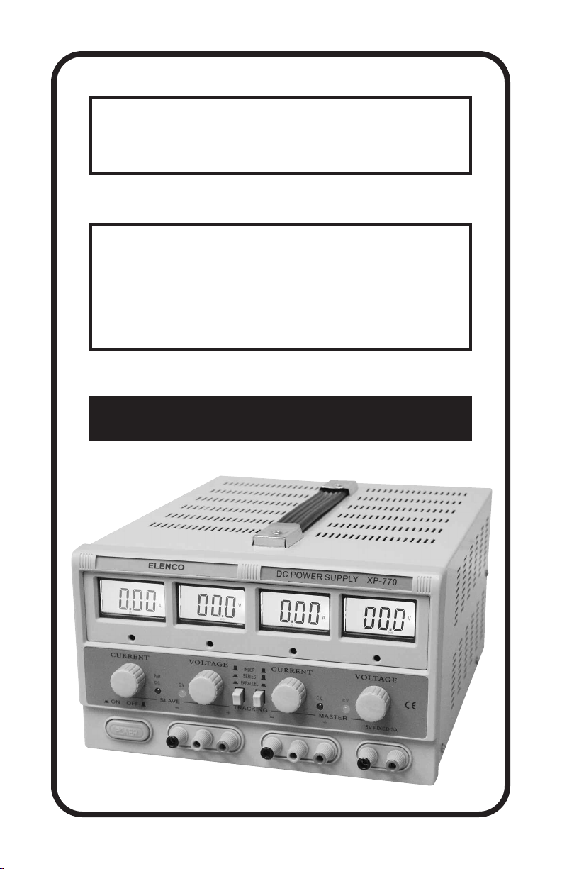
Triple-output Regulated DC
Power Supply
Instruction
Manual
Model XP-770
Page 2

COMPONENT OVERVIEW
5
16171819 2021
12
810 79 1112
131415
4
36
-1-23-2-
22
24
Page 3

1. Voltage and current indication for master output
2. Voltage and current indication for slave output
3. Voltage adjustment of master output
4. Current adjustment of master output
5. Voltage adjustment of slave output
6. Current adjustment of slave output
7. Constant voltage mode indicator light for master output
8. Constant current mode indicator light for master output
9. Constant voltage mode indicator light for slave output
10. Constant current mode indicator light for slave output and
double current output indicator light in parallel mode
11. Independent, series and parallel selector switch
12. Independent, series and parallel selector switch
13. Positive output terminal of master output
14. Ground connection terminal of case
15. Negative output terminal of master output
16. Positive output terminal of slave output
17. Ground connection terminal of case
18. Negative output terminal of slave output
19. Main power on/off switch
20. Fixed 5V positive output terminal
21. Fixed 5V negative output terminal
22. AC input voltage switch
23. AC input
24. Fuse holder
Page 4

INTRODUCTION
Congratulations on your selection of a top quality power supply! The XP770 is a triple-output regulated power supply providing two variable outputs
(0-20V@ 2A) and one fixed (5V @ 3A). Four LCD displays allowing the
output voltages and currents to be displayed simultaneously. The variable
outputs can work independently, in series, or in parallel modes.The highest
output voltage is the sum of twice the voltage value in series mode and
the highest output current is the sum of twice the current value when in
parallel mode.
FEATURES
Four LCD displays for voltage and current
Independent voltage and current controls
Constant voltage (CV) or constant current (CC) operation
LED indication for CV and CC for variable outputs
Series and parallel mode for variable outputs
Overload and short protected.
Selectable AC input voltage, 115 or 230VAC
SAFETY PRECAUTIONS
Certain safety precautions must be observed when this power supply is
used with external circuits that are connected to AC power lines. There is
always some danger when working with electrical equipment or circuits
that operate at hazardous voltages. You should thoroughly familiarize
yourself with the equipment before using it. High voltage may appear at
unexpected points in defective equipment.
The XP-770 is equipped with a three-wire line cord which grounds the
chassis to power line ground. Do not cut off or disable the ground plug.
The power supply secondary circuits are isolated from the 115/230V
primary circuit via the power transformer. When working with other
equipment, this may not always be the case. Always be familiar with the
equipment rating. Keep in mind that defective equipment can have
dangerous voltages in unexpected places.
OPERATING INSTRUCTIONS
1. Set the AC input voltage switch on the back to the correct setting and
the correct fuse (4A - 115V, 2A - 230V) installed.
2. Set the power switch to the off position.
3. Plug the power cord into the power socket on the back of the unit.
4. Plug the power cord into an AC output. Note: Make sure enough space
is left for heat dissipation.
-3-
Page 5

5. Check that the voltage rating of the equipment does not exceed the
power supply’s rating.
Dual Power Supply Used in Independent Mode
Set the tracking switches 11 & 12 to the OUT position.
Constant Voltage Mode
1. Turn the master and slave output current adjustment control knobs (4
& 6) clockwise to the maximum position. Adjust the voltage adjustment
control knobs (3 & 5) counter clockwise to the minimum position.
2. Turn the power switch ON. Both CV LED’s should be lit.
3. Adjust the master and slave voltage adjustment control knobs (3 & 5)
to the desired voltage.
4. Connect the positive and negative output terminals to a load or similar
component.
Constant Current Mode
1. Turn the master and slave output voltage adjustment control knobs (3
& 5) clockwise to the maximum position. Adjust the current adjustment
control knobs (4 & 6) counter clockwise to the minimum position.
2. Turn the power switch ON. Both CC LED’s should be lit.
3. Connect the positive and negative output terminals to a load or similar
component.
4. Adjust the master and slave output current adjustment control knobs (4
& 6) to give the desired current.
Current Limit Protection Mode
(DC power supply: Output voltage less than 20V, or output current less than 2A)
1.
Turn the master and slave output current adjustment control knobs (4 &
6) counter-clockwise to the minimum position. Turn the power switch ON.
2. Adjust the master and slave voltage adjustment control knobs (3 & 5)
to give the desired output voltage and then connect the output terminals
13 with 15 and 16 with 18 respectively.
3. Adjust the master and slave output current adjustment control knobs (4
& 6) to give the desired value or current limit. Remove the connection
between 13 & 15 and 16 & 18, and connect the load.
-4-
Page 6

Dual Power Supply Used in Series Mode
1. Set the tracking switch 12 to the IN position and tracking switch 11 to
the OUT position. Adjust the master and slave output current
adjustment control knobs (4 & 6) clockwise to the maximum position.
Adjust controls 3 and 5 to the desired output voltage. The voltage of the
master output should be tracked by the slave output. The highest output
voltage is the sum of the value of both master and slave outputs when
connecting the load to terminals 13 & 18.
2. In Series Mode, the current adjustment is independent. If the slave
control (6) is not at the maximum position but at a current limiting
position (CC LED lit), then the voltage of the slave output will not track
the master output.
3. In Series Mode, terminals 15 & 16 should be connected together with
a thick conductive wire to prevent damage to the unit in the event of an
overload.
4. In Series Mode, remove any connection between the master or slave
negative terminals and the ground connection terminals. Otherwise, it
is possible to short-circuit the slave output.
Dual Power Supply Used in Parallel Mode
1. Set the tracking switches 11 & 12 to the IN position. The master and
slave outputs will now be in parallel mode. Adjust control 3 to the
desired output voltage and the voltage of the master and slave outputs
should change identically.
2. In Parallel Mode, the output current adjusted by the master output
current adjustment control knob (4) and the slave control (6) has no
effect.The maximum output current is the sum of the master and slave
output currents.
3. In Parallel Mode, terminals 13 & 16 and 15 & 18 should be connected
respectively with thick conductive wire to prevent damage to the unit in
the event of an overload.
CAUTION:
• In the event of a short circuit at the output, the current will limit at the
value set by the current controls. However, the unit should be turned
OFF and the short circuit removed before continuing use.
• The unit must be unplugged before servicing. Servicing should be
performed by a qualified repairperson with knowledge in electrical
hazards.
-5-
Page 7

• The unit should be stored in a dry and well-ventilated place and the
power cord removed if storing for a long period of time.
• Never place any objects on the power supply.
• Do not obstruct the ventilation holes.
• Avoid contacting the heat sink of the power supply as it can become very
hot. Contacting the heat sink when it is hot could result in skin burns or
damage to the equipment in contact with them.
•
Never move or pull the power supply using the power cord or output lead.
• The XP-770 is designed for INDOOR USE ONLY.
SPECIFICATIONS
Output
Voltage
0-20V 0-2A
5V + 0.25V
Output
Current
3A < 1.5mV – < 15mV –
Line Regulation Load Regulation Ripple & Noise
CV CC CV CC CV CC
< 0.01% +2mV
< 0.2% +2mA
< 0.01% +3mV
< 0.2% +3mA
< 0.5mV rms
< 5mV rms
< 3mA rms
Number of Outputs Three / two variable and one fixed.
Input Voltage 104 – 127VAC (60Hz) • 207 – 253VAC (50Hz)
Protection Current limit and short circuit protection.
Display Accuracy Voltage +1% +2 digits, Current +2% +2 digits
O
Environment: 32
Dimensions (WxHxD)
F - 104OF (0OF - +40OC), relative humidity <90%
(10.2 x 6.5 x 14”), (25.9 x 16.5 x 35.6cm)
Weight 12.9 lbs. / 5.85 kg.
–
-6-
Page 8

MAINTENANCE
Cleaning – Using a soft moistened cloth, remove any dirt on the outside of
the case. The power supply should be used in a normal working
environment.
Servicing – If the unit becomes inoperative or damage, Elenco®Electronics
or a qualified repairperson should only perform the repair and calibration.
Fuse Replacement
The power supply will not work if the fuse is blown or not installed. Check
and repair any existing problems before installing new fuse. Only use fuses
with same specification as original the one.
Warning - To prevent fire use only 250V or greater with the specified
current.
1. Disconnect the AC power before replacing the fuse.
2. Insert a small screwdriver into fuse holder slot (located between fuse
holder and receptacle) and pry fuse holder from receptacle.
3. Replace the blown fuse and insert holder into receptacle. Be sure that
the fuse is installed so that the correct line voltage is selected.
Elenco®fuse part numbers:
AC Power 230V 2A fuse 250V (5 x 20mm) Part #: 533020
AC Power 115V 4A fuse 250V (5 x 20mm) Part #: 531044
4. Plug line cord back into the AC output and test unit.
TWO YEAR WARRANTY
All Elenco®models are guaranteed for two full years on all parts
and service. For the first 3 months, your power supply is covered at
absolutely no charge. For the remaining 21 months, a nominal
service charge is required to cover shipping and handling.
When returning merchandise for repair, please include proof
of purchase, a brief letter of explanation of problem, and
sufficient packing material. Before returning any
merchandise please call our service department at (847) 5413800 to obtain a return authorization number (RMA).
Elenco®Electronics, Inc.
150 Carpenter Avenue • Wheeling, IL 60090 • (847) 541-3800
Website: www.elenco.com • e-mail: elenco@elenco.com
 Loading...