

Page 1

Copyright © 2014 by Elenco®Electronics, Inc. All rights reserved. No part of this book shall be reproduced by 753093
any means; electronic, photocopying, or otherwise without written permission from the publisher.
U.S. Patents 7,144,255; 7,273,377;
patents pending
Page 2
Table of Contents
Basic Troubleshooting 1
How to Use It 2
Parts List 3, 4
About Your Circuit Maker Parts 5, 6
Introduction to Electricity 7
WARNING: SHOCK HAZARD -
Never connect Circuit Maker to the electrical
outlets in your home in any way!
Basic Troubleshooting
1. Most circuit problems are due to
incorrect assembly, always doublecheck that your circuit exactly matches
the drawing for it.
2. Be sure that parts with
positive/negative markings are
positioned as per the drawing.
3. Be sure that all connections are
securely snapped.
!
WARNING: Always check your wiring before
turning on a circuit. Never leave a circuit
unattended while the batteries are installed.
Never connect additional batteries or any
other power sources to your circuits.
Discard any cracked or broken parts.
Adult Supervision: Because children’s
abilities vary so much, even with age
groups, adults should exercise discretion
as to which experiments are suitable and
safe (the instructions should enable
supervising adults to establish the
DOs and DON’Ts of Building Circuits 8
Advanced Troubleshooting 9
Project Listings 10, 11
Projects 1 - 203 12 - 77
Other Circuit Maker Products 78
WARNING: CHOKING HAZARD -
Small parts. Not for children under
3 years.
Conforms to all applicable U.S. government
requirements.
experiment’s suitability for the child). Make
sure your child reads and follows all of the
relevant instructions and safety
procedures, and keeps them at hand for
reference.
This product is intended for use by adults
and children who have attained sufficient
maturity to read and follow directions and
warnings.
Never modify your parts, as doing so may
disable important safety features in them,
and could put your child at risk of injury.
4. Try replacing the batteries.
ELENCO
®
is not responsible for parts
damaged due to incorrect wiring.
Note: If you suspect you have damaged parts,
you can follow the Advanced Troubleshooting
procedure on page 9 to determine which ones
need replacing.
-1-
Batteries:
!
● Use only 1.5V “AA” type, alkaline batteries
(not included).
● Insert batteries with correct polarity.
● Non-rechargeable batteries should not be
recharged. Rechargeable batteries should
only be charged under adult supervision,
and should not be recharged while in the
product.
● Do not mix old and new batteries.
● Remove batteries when they are used up.
● Do not connect batteries or battery holders
in parallel.
● Do not mix alkaline, standard (carbonzinc), or rechargeable (nickel-cadmium)
batteries.
● Do not short circuit the battery terminals.
● Never throw batteries in a fire or attempt to
open its outer casing.
● Batteries are harmful if swallowed, so keep
away from small children.
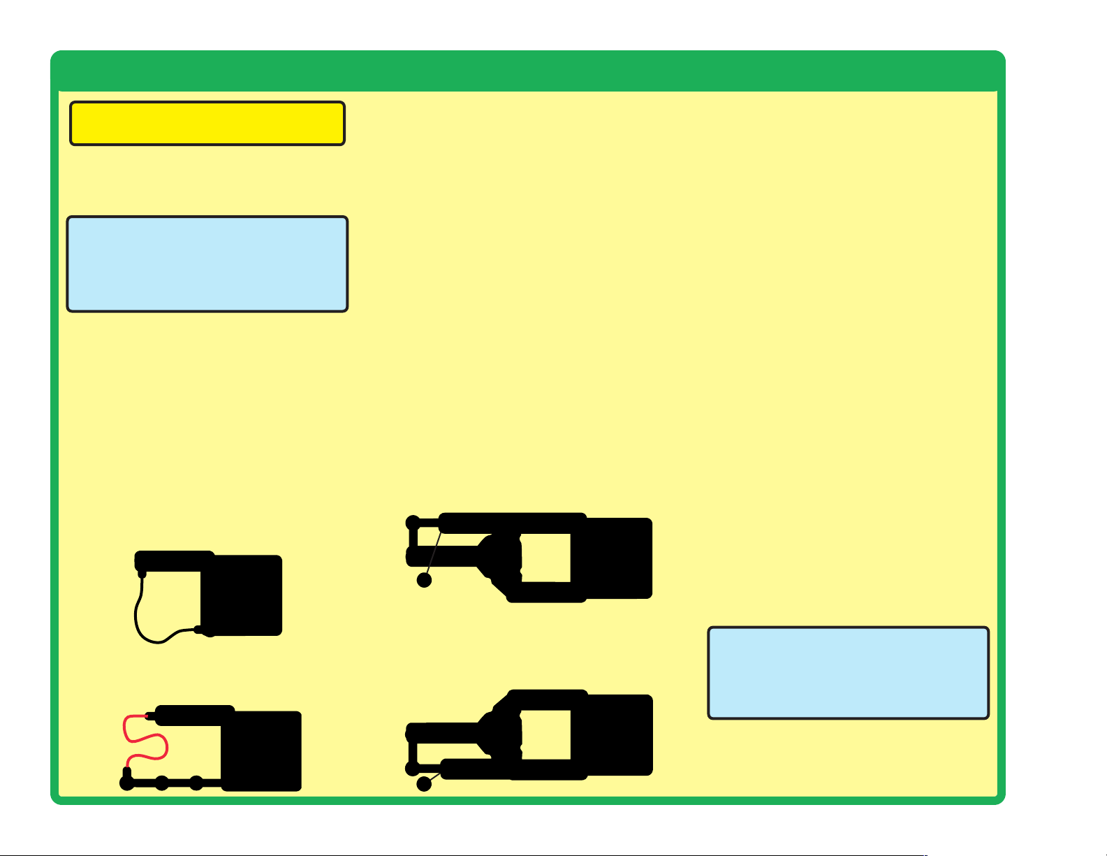
Page 3
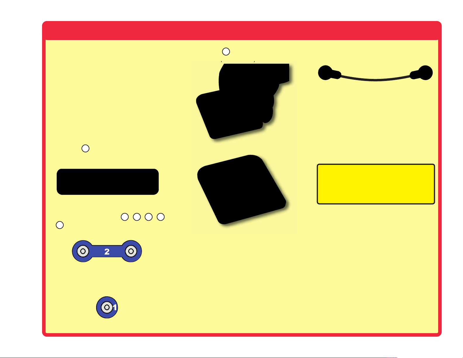
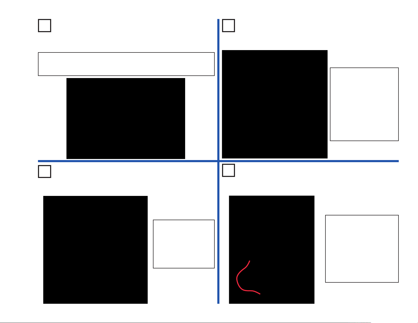
How to Use Circuit Maker Sound Plus 200
Circuit Maker Sound Plus 200 uses building
blocks with snaps to build the different
electrical and electronic circuits in the projects.
Each block has a function: there are switch
blocks, light blocks, battery blocks, different
length wire blocks, etc. These blocks are
different colors and have numbers on them so
that you can easily identify them. The blocks
you will be using are shown as color symbols
with level numbers next to them, allowing you
to easily snap them together to form a circuit.
For Example:
This is the switch block which is green and has
the marking on it. The part symbols in this
booklet may not exactly match the appearance
of the actual parts, but will clearly identify them.
This is a wire block which is blue and comes
in different wire lengths.
This one has the number , , , ,
or on it depending on the length of the wire
6
connection required.
There is also a 1-snap wire that is used as a
spacer or for interconnection between different
layers.
S2
2
3 4 5
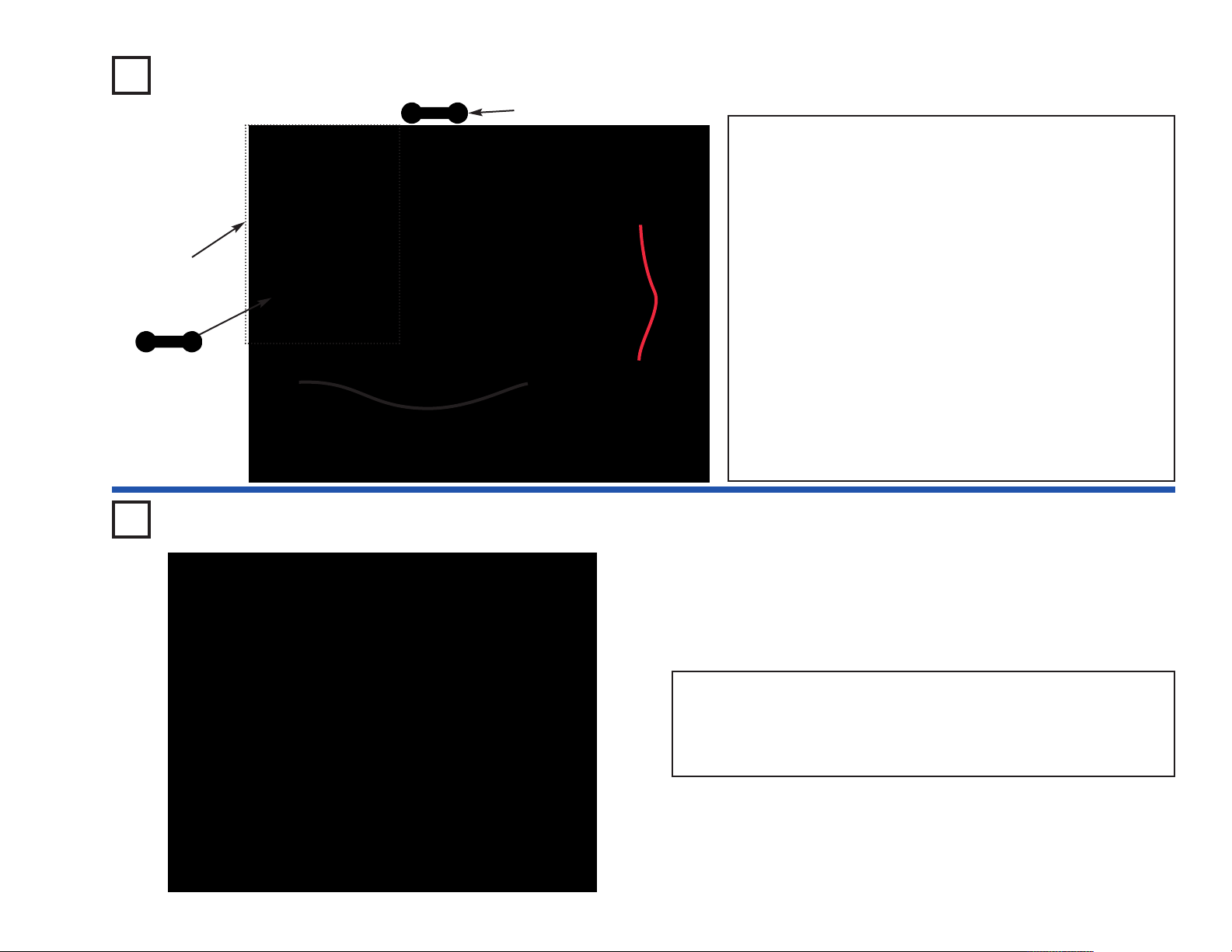
You need a power source to build each circuit.
This is labeled and requires three (3) 1.5V
“AA” batteries (not included).
A large clear plastic base grid is included with
this kit to help keep the circuit blocks properly
spaced. You will see evenly spaced posts that
the different blocks snap into. The base has
rows labeled A-G and columns labeled 1-10.
Next to each part in every circuit drawing is a
small number in black. This tells you which
level the component is placed at. Place all
parts on level 1 first, then all of the parts on
level 2, then all of the parts on level 3, etc.
B3
Some circuits use the jumper wires to make
unusual connections. Just clip them to the
metal snaps or as indicated.
Note: While building the projects, be careful
not to accidentally make a direct connection
across the battery holder (a “short circuit”),
as this may damage and/or quickly drain the
batteries.
-2-
Page 4
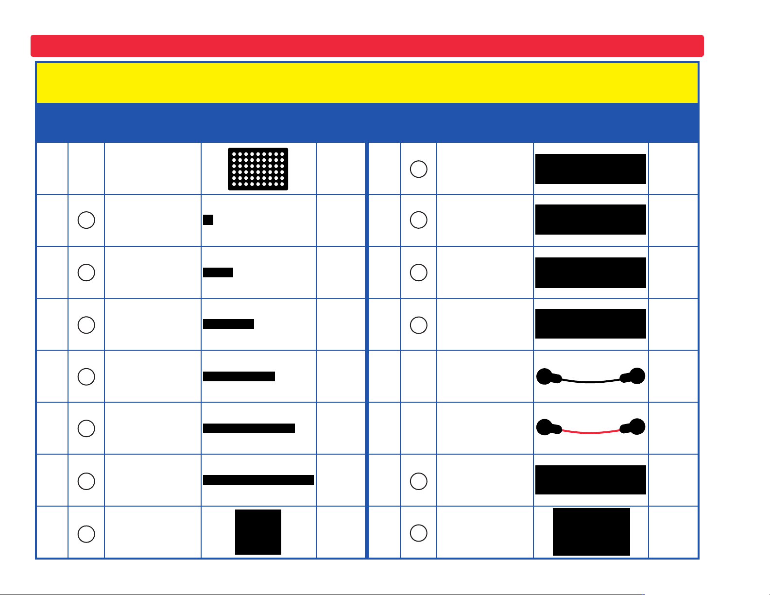
Parts List (Colors and styles may vary) Symbols and Numbers
Important: If any parts are missing or damaged, DO NOT RETURN TO RETAILER. Call customer service toll-
free at (800) 533-2441 or e-mail us at: help@elenco.com.
Qty. ID Name Symbol Part # Qty. ID Name Symbol Part #
r 1
r 4
r 7
r 4
r 1
r 1
Base Grid
(11.0” x 7.7”)
1
1-Snap Wire 6SC01
2
2-Snap Wire 6SC02
3-Snap Wire
3
4-Snap Wire
4
5
5-Snap Wire 6SC05
6SCBG
6SC03
6SC04
r 1
r 1
r 1
r 1
r 1
r 1
C2
C3
C4
D1
0.1mF Capacitor 6SCC2
10mF Capacitor 6SCC3
100mF Capacitor
6SCC4
Red Light
Emitting
6SCD1
Diode (LED)
Jumper Wire
(Black)
6SCJ1
Jumper Wire
(Red)
6SCJ2
r 1
r 1
6
B3
6-Snap Wire 6SC06
Battery Holder uses 3 1.5V type
6SCB3
AA (not included)
r 1
r 1
L4
Q1
Lamp
6SCL4
PNP Transistor 6SCQ1
Page 5
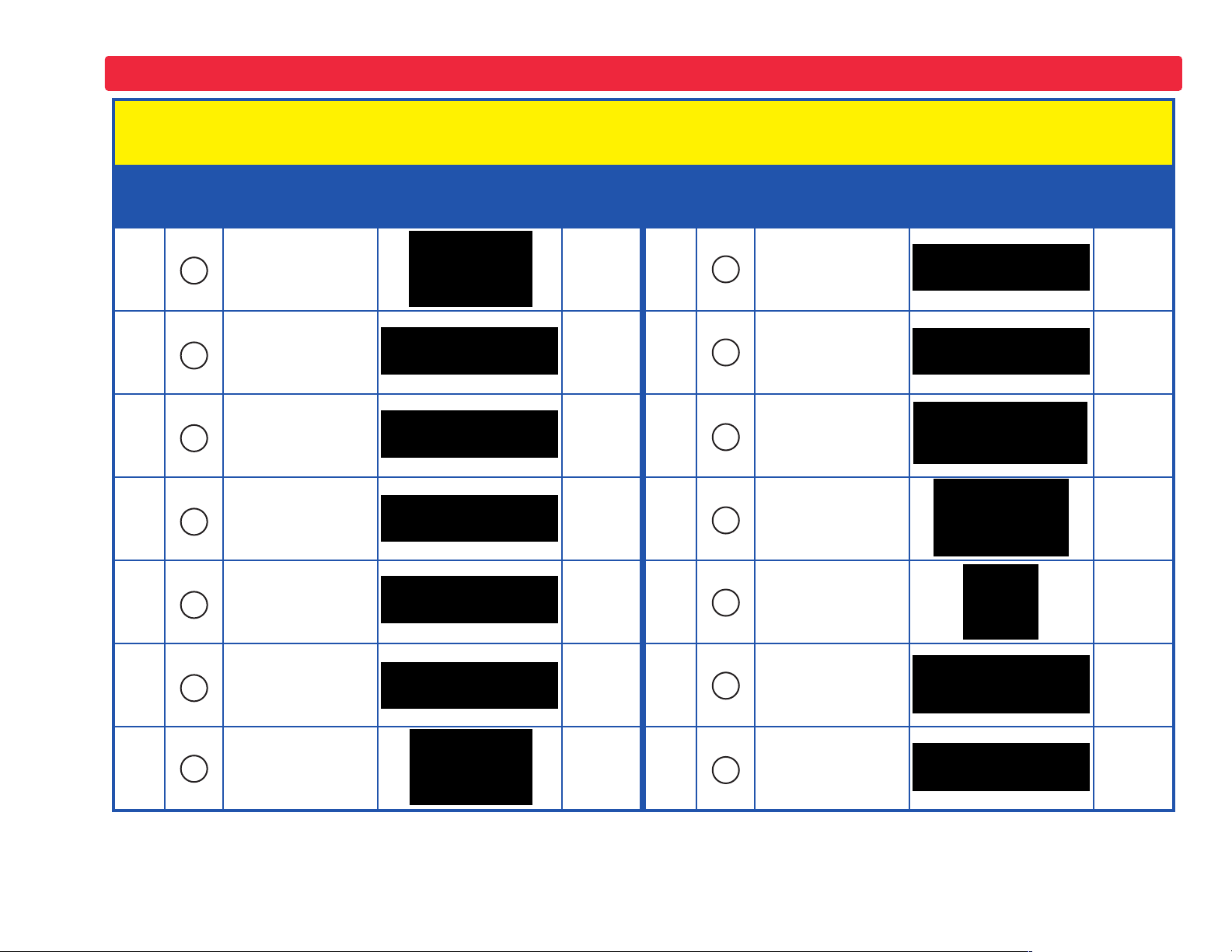
Parts List (Colors and styles may vary) Symbols and Numbers
Important: If any parts are missing or damaged, DO NOT RETURN TO RETAILER. Call customer service toll-
free at (800) 533-2441 or e-mail us at: help@elenco.com.
Qty. ID Name Symbol Part # Qty. ID Name Symbol Part #
r 1
r 1
r 1
r 1
r 1
r 1
Q2
R1
R2
R3
R5
RP
NPN Transistor 6SCQ2
100W Resistor 6SCR1
1KW Resistor 6SCR2
5.1KW Resistor 6SCR3
100KW Resistor 6SCR5
Photoresistor 6SCRP
r 1
r 1
r 1
r 1
r 1
r 1
S1
S2
SP2
U3
U6
WC
Slide Switch 6SCS1
Press Switch 6SCS2
Speaker 6SCSP2
Space War
Integrated
6SCU3
Circuit (IC)
Recording
Integrated
6SCU6
Circuit (IC)
Whistle Chip 6SCWC
r 1
RV
Adjustable
Resistor
6SCRV
r 1
X1
Microphone 6SCX1
-4-
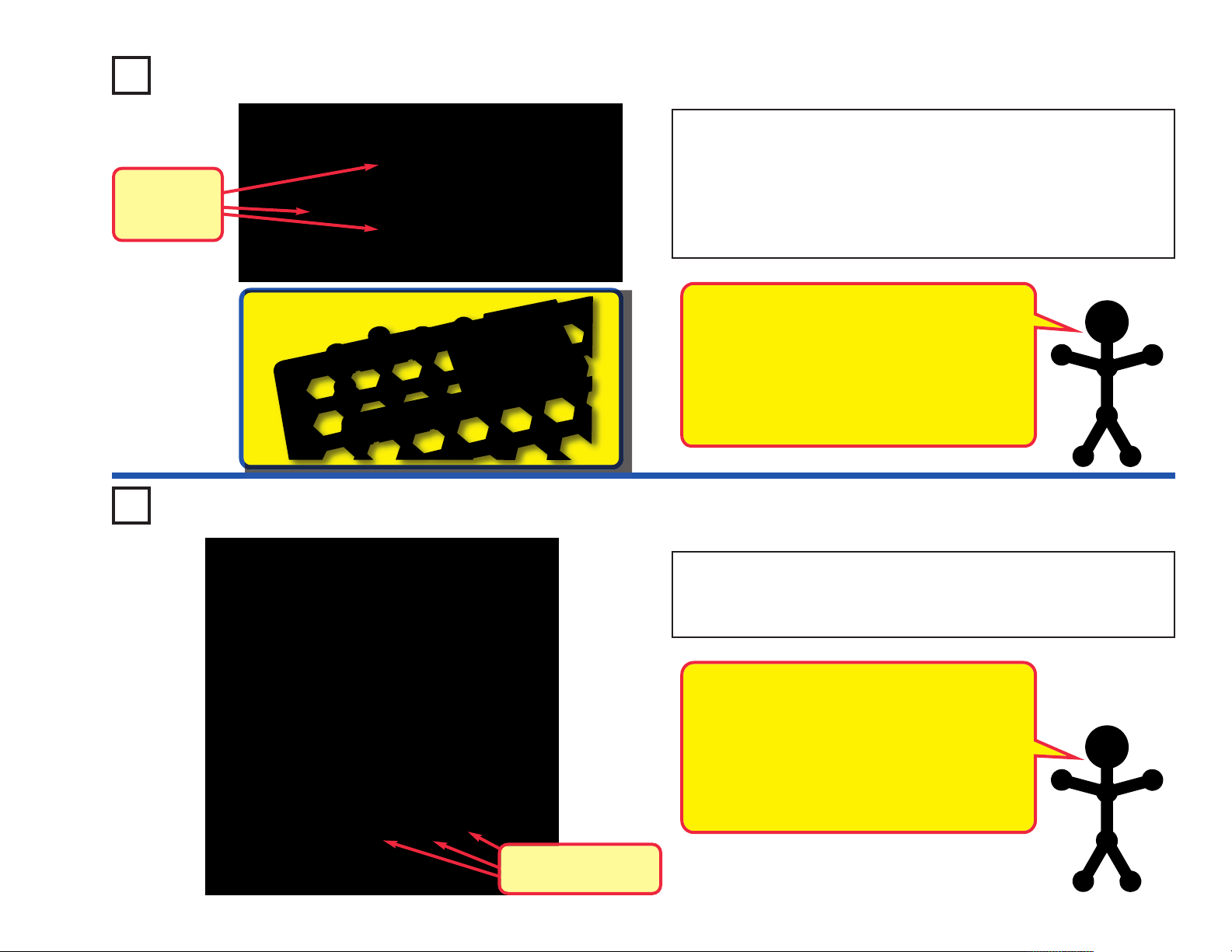
Page 6
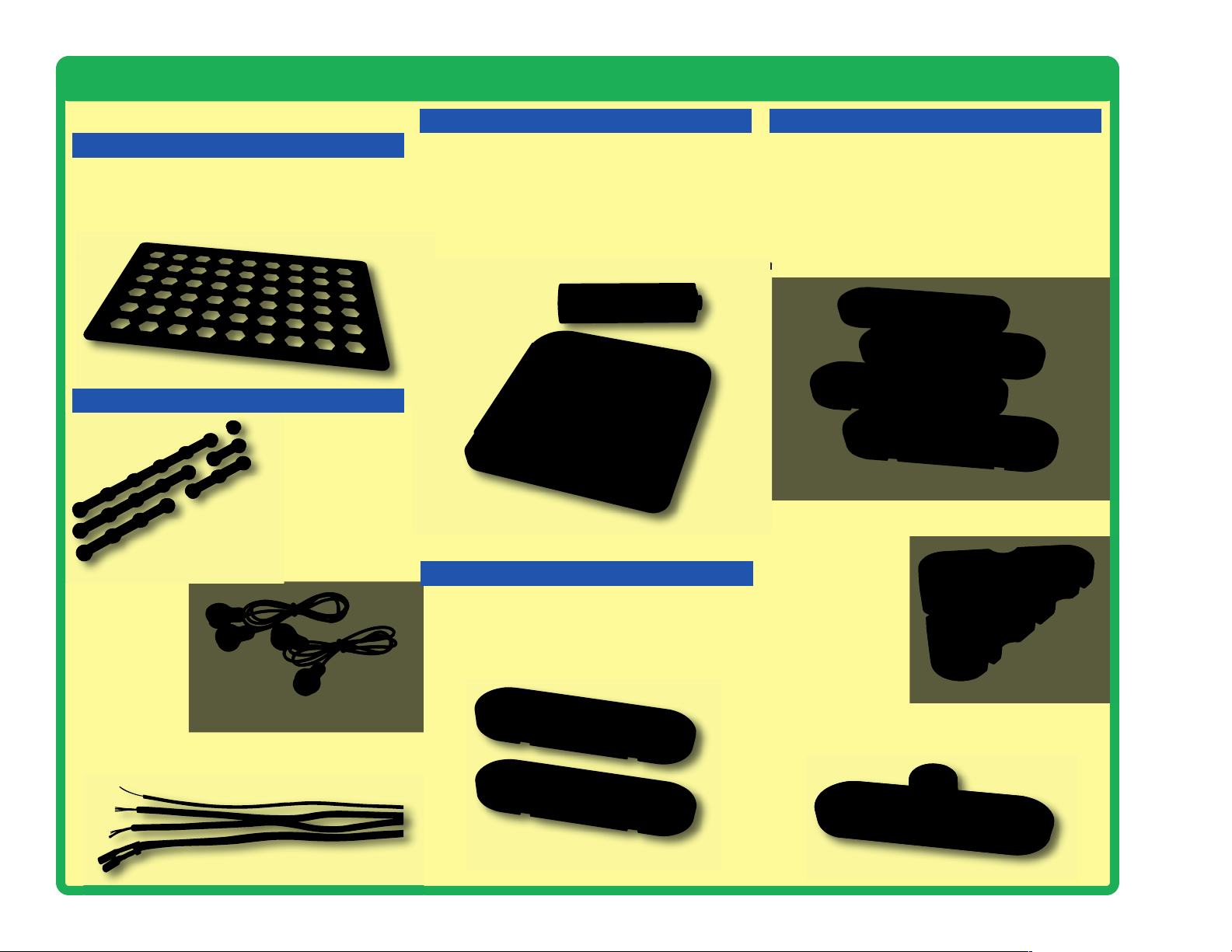
About Your Circuit Maker Sound Plus 200 Parts
(Part designs are subject to change without notice).
BASE GRID
The base grid is a platform for mounting parts and
wires. It functions like the printed circuit boards used
in most electronic products, or like how the walls are
used for mounting the electrical wiring in your home.
SNAP WIRES & JUMPER WIRES
The blue snap wires
are wires used to
connect components.
They are used to transport
electricity and do not affect
circuit performance. They come in
different lengths to allow orderly
arrangement of connections on the base grid.
The red and black
jumper wires make
flexible connections
for times when using
the snap wires would be difficult.
They also are used to make
connections off the base grid.
Wires transport electricity just like pipes are used to
transport water. The colorful plastic coating protects
them and prevents electricity from getting in or out.
BATTERY HOLDER
The batteries (B3) produce an electrical voltage using
a chemical reaction. This “voltage” can be thought of
as electrical pressure, pushing electricity through a
circuit just like a pump pushes water through pipes.
This voltage is much lower and much safer than that
used in your house wiring. Using more batteries
increases the “pressure”, therefore, more electricity
flows.
Battery Holder (B3)
SLIDE & PRESS SWITCHES
The slide and press switches (S1 & S2) connect
(pressed or “ON”) or disconnect (not pressed or
“OFF”) the wires in a circuit. When ON they have no
effect on circuit performance. Switches turn on
electricity just like a faucet turns on water from a pipe.
RESISTORS
Resistors “resist” the flow of electricity and are used to
control or limit the current in a circuit. Circuit Maker Skill
Builder 125 includes 100W (R1), 1kW (R2), 5.1kW (R3),
and 100kW (R5) resistors (“k” symbolizes 1,000, so
R3 is really 5,100W). Materials like metal have very low
resistance (<1W), while materials like paper, plastic,
and air have near-infinite resistance. Increasing circuit
resistance reduces the flow of electricity.
Resistors (R1, R2, R3, & R5)
The adjustable resistor (RV) is
a 50kW resistor but with
a center tap that can
be adjusted between
200W and 50kW.
Adjustable
Resistor (RV)
The photoresistor (RP) is a light-sensitive resistor, its
value changes from nearly infinite in total darkness to
about 1,000W when a bright light shines on it.
-5-
Slide & Press Switches (S1 & S2)
Photoresistor (RP)
Page 7
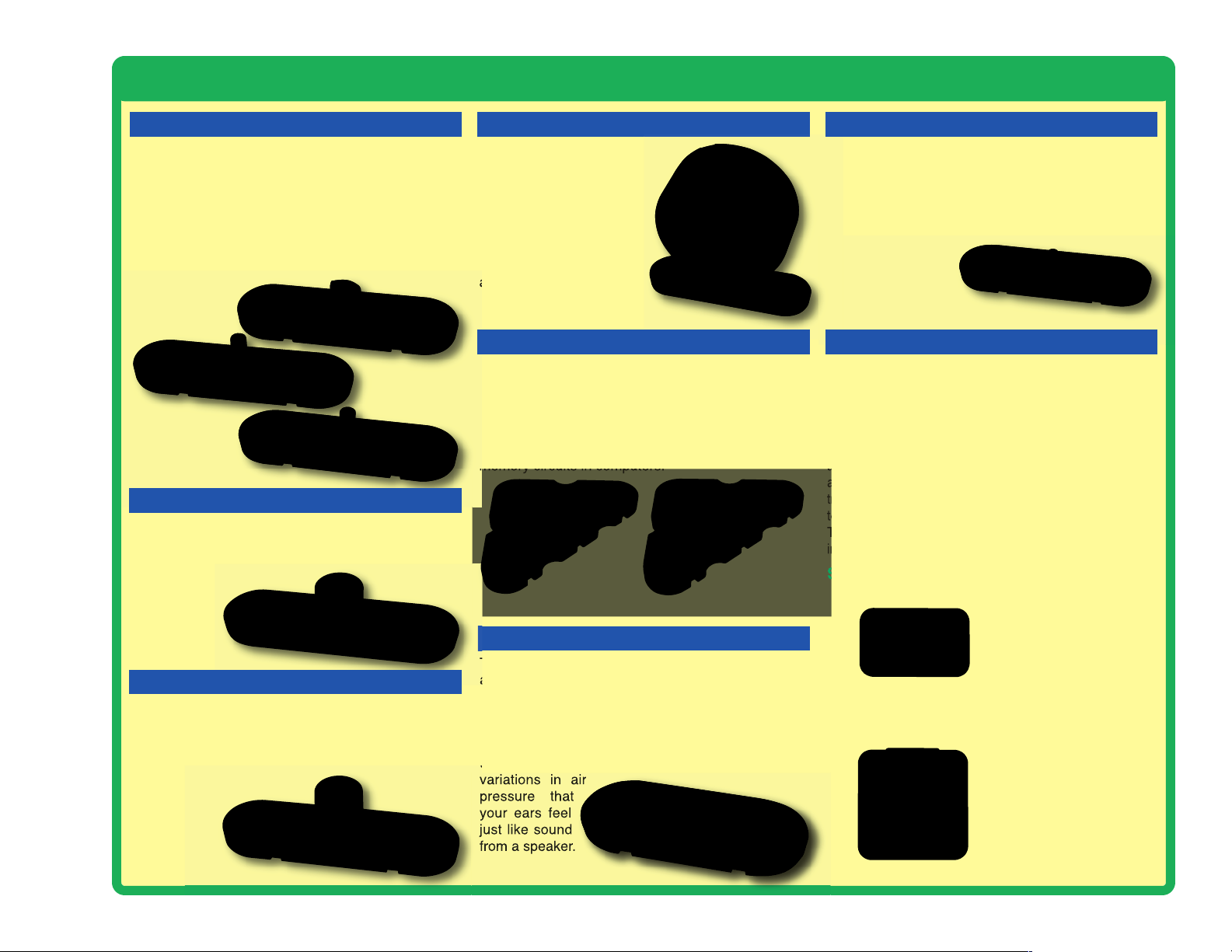
About Your Circuit Maker Sound Plus 200 Parts
CAPACITORS
Capacitors are components that can store electrical
pressure (voltage) for periods of time, higher values
have more storage. Because of this storage ability
they block unchanging voltage signals and pass fast
changing voltages. Capacitors are used for filtering
and oscillation circuits. This kit includes 0.1mF (C2),
10mF (C3), and 100mF (C4) capacitors. The whistle
chip (WC) also acts like a 0.02mF capacitor in addition
to its sound
properties.
Capacitors
(C2, C3, & C4)
MICROPHONE
The microphone (X1) is actually a resistor that
changes in value when changes in air pressure
(sounds) apply pressure to its surface.
Microphone
(X1)
LAMP
A light bulb, such as in the 4.5V lamp (L4), contains a
special thin high-resistance wire. When a lot of
electricity flows through, this wire gets so hot it glows
bright. Voltages above the bulb’s rating can burn out
the wire.
Lamp (L4)
SPEAKER
The speaker (SP2) converts
electricity into sound by making
mechanical vibrations. These
vibrations create variations
in air pressure, which travel
across the room. You “hear”
sound when your ears feel
these air pressure variations.
Speaker (SP2)
TRANSISTORS
The PNP transistor (Q1) and NPN transistor (Q2)
are components that use a small electric current to
control a large current, and is used in switching,
amplifier, and buffering applications. Transistors are
easy to miniaturize, and are the main building blocks
of integrated circuits including the microprocessor and
memory circuits in computers.
PNP Transistor (Q1)
NPN Transistor (Q2)
WHISTLE CHIP
The whistle chip (WC) contains two thin plates. When
an electrical signal is applied across them they will
stretch slightly in an effort to separate (like two
magnets opposing each other), when the signal is
removed they come back together. If the electrical
signal applied across them is changing quickly, then
the plates will vibrate. These vibrations create
variations in air
pressure that
your ears feel
just like sound
from a speaker.
Whistle Chip (WC)
LED
The red LED (D1) is a light emitting diode and may be
thought of as a special one-way light bulb. In the
“forward” direction, (indicated by the “arrow” in the
symbol) electricity flows if the voltage exceeds a turnon threshold (about 1.5V); brightness then increases.
A high current will burn out an LED, so the current
must be limited by
other components in
the circuit. LEDs
block electricity in the
“reverse” direction.
LED (D1)
INTEGRATED CIRCUITS (ICs)
Some types of electronic components can be superminiaturized, allowing many thousands of parts to fit into an
area smaller that your fingernail. These “integrated circuits”
(ICs) are used in everything from simple electronic toys to the
most advanced computers. The space war and recording IC
modules (U3 & U6) in Circuit Maker Sound Plus 200 are
actually modules containing specialized sound-generation ICs
and other supporting components (resistors, capacitors, and
transistors) that are always needed with them. This was done
to simplify the connections you need to make to use them.
The descriptions for these modules are given here for those
interested; see the projects for connection examples:
Space War IC:
(+)
IN1
OUT
IN2(–)
Recording IC Module:
Mic +
Mic –
(+)
(–) RCPlay
Connections:
(+) - power from batteries
(–) - power return to batteries
OUT - output connection
IN1, IN2 - control inputs
Connect each control input to
(–) power to sequence
through 8 sounds.
Connections:
(+) - power from batteries
(–) - power return to batteries
RC - record
Play - play
OUT - output connection
OUT
Mic + - microphone input
Mic – - microphone input
See Project #4 for example of
proper connections.
-6-
Page 8
Introduction to Electricity
What is electricity? Nobody really knows. We only know how to produce it,
understand its properties, and how to control it. Electricity is the movement of subatomic charged particles (called electrons) through a material due to electrical
pressure across the material, such as from a battery.
Power sources, such as batteries, push electricity through a circuit, like a pump
pushes water through pipes. Wires carry electricity, like pipes carry water. Devices
like LEDs, motors, and speakers use the energy in electricity to do things. Switches
and transistors control the flow of electricity like valves and faucets control water.
Resistors limit the flow of electricity.
The electrical pressure exerted by a battery or other power source is called
voltage and is measured in volts (V). Notice the “+” and “–” signs on the battery;
these indicate which direction the battery will “pump” the electricity.
The electric current is a measure of how fast electricity is flowing in a wire, just
as the water current describes how fast water is flowing in a pipe. It is expressed
in amperes (A) or milliamps (mA, 1/1,000 of an ampere).
The “power” of electricity is a measure of how fast energy is moving through a
wire. It is a combination of the voltage and current (Power = Voltage x Current). It
is expressed in watts (W).
The resistance of a component or circuit represents how much it resists the
electrical pressure (voltage) and limits the flow of electric current. The relationship
is Voltage = Current x Resistance. When the resistance increases, less current
flows. Resistance is measured in ohms (W), or kilo ohms (kW, 1,000 ohms).
There are two ways of arranging parts in a circuit, in series or
in parallel. Here are examples:
Series Circuit
Nearly all of the electricity used in our world is produced at enormous generators
driven by steam or water pressure. Wires are used to efficiently transport this
energy to homes and businesses where it is used. Motors convert the electricity
back into mechanical form to drive machinery and appliances. The most important
aspect of electricity in our society is that it allows energy to be easily transported
over distances.
Note that “distances” includes not just large distances but also tiny distances. Try
to imagine a plumbing structure of the same complexity as the circuitry inside a
portable radio - it would have to be large because we can’t make water pipes so
small. Electricity allows complex designs to be made very small.
-7-
Parallel Circuit
Placing components in series increases the resistance; highest
value dominates. Placing components in parallel decreases the
resistance; lowest value dominates.
The parts within these series and parallel sub-circuits may be
arranged in different ways without changing what the circuit
does. Large circuits are made of combinations of smaller series
and parallel circuits.
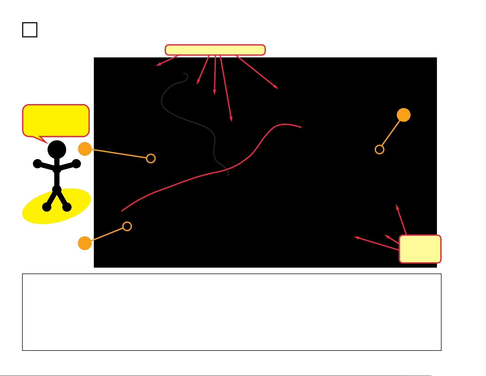
Page 9
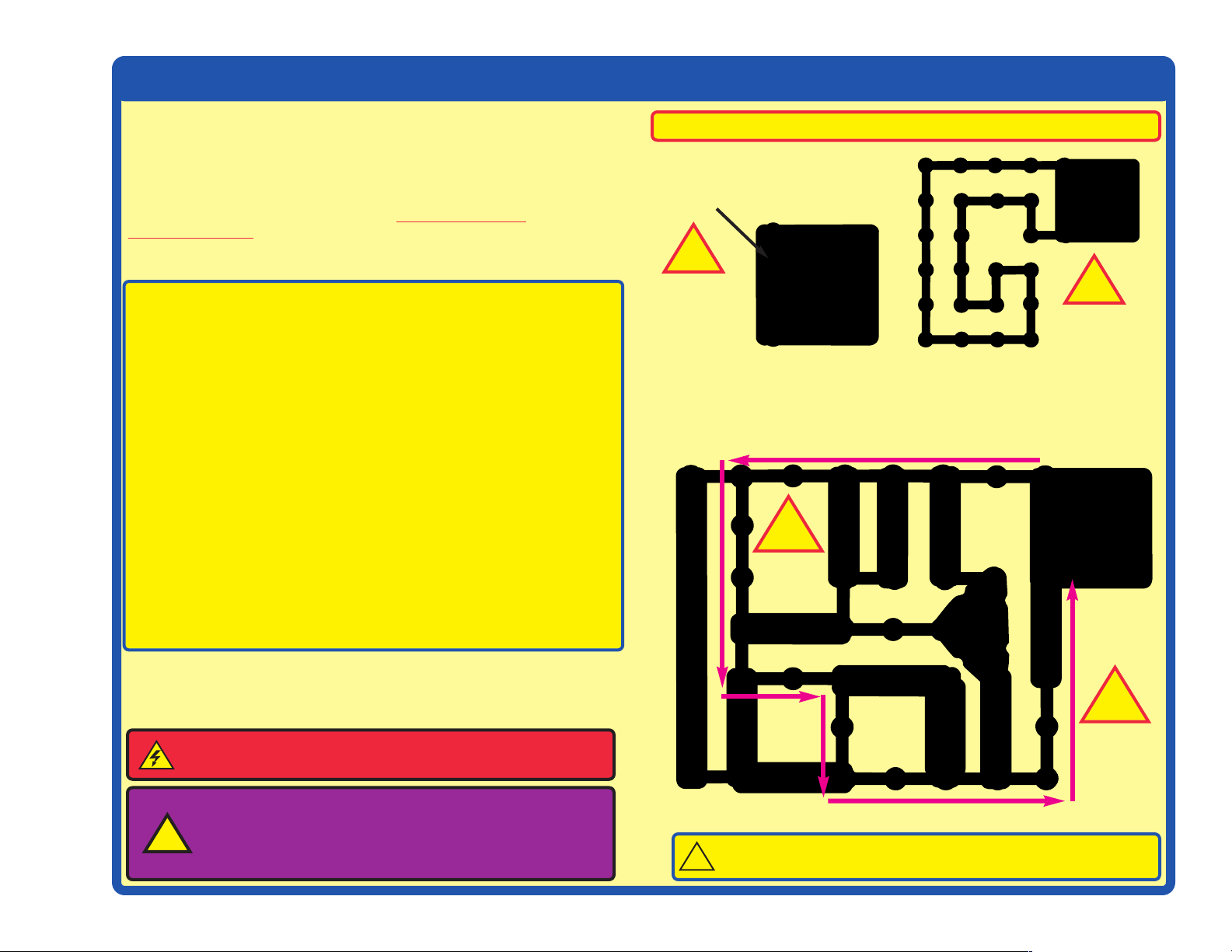
DOs and DON’Ts of Building Circuits
After building the circuits given in this booklet, you may wish to experiment on
your own. Use the projects in this booklet as a guide, as many important design
concepts are introduced throughout them. Every circuit will include a power
source (the batteries), a resistance (which might be a resistor, capacitor, speaker,
integrated circuit, etc.), and wiring paths between them and back. You must be
careful not to create “short circuits” (very low-resistance paths across the
batteries, see examples at right) as this will damage components
drain your batteries. Only connect the ICs using configurations given in the
projects, incorrectly doing so may damage them. ELENCO®is not responsible
for parts damaged due to incorrect wiring.
Here are some important guidelines:
ALWAYS USE EYE PROTECTION WHEN EXPERIMENTING ON YOUR
OWN.
ALWAYS include at least one component that will limit the current through a
circuit, such as the speaker, lamp, ICs (which must be connected
properly), motor, photoresistor, or resistor.
ALWAYS use the LED, NPN transistor, and switches in conjunction with other
components that will limit the current through them. Failure to do so
will create a short circuit and/or damage those parts.
ALWAYS disconnect your batteries immediately and check your wiring if
something appears to be getting hot.
ALWAYS check your wiring before turning on a circuit.
ALWAYS connect capacitors so that the “+” side gets the higher voltage.
ALWAYS connect ICs using configurations given in the projects or as per the
connection descriptions for the parts.
NEVER connect to an electrical outlet in your home in any way.
NEVER leave a circuit unattended when it is turned on.
NEVER touch the motor when it is spinning at high speed.
and/or quickly
Examples of SHORT CIRCUITS - NEVER DO THESE!!!
Placing a 3-snap wire directly
across the batteries is a
SHORT CIRCUIT.
!
NEVER
DO!
This is also a SHORT CIRCUIT.
When the slide switch (S1) is turned on, this large circuit has a SHORT
CIRCUIT path (as shown by the arrows). The short circuit prevents any
other portions of the circuit from ever working.
!
NEVER
DO!
!
NEVER
DO!
For all of the projects given in this book, the parts may be arranged in different
ways without changing the circuit. For example, the order of parts connected in
series or in parallel does not matter — what matters is how combinations of these
sub-circuits are arranged together.
WARNING: SHOCK HAZARD -
Sound Plus 200 to the electrical outlets in your home in any way!
Warning to Circuit Maker owners: Do not connect
additional voltage sources from other sets, or you
!
may damage your parts. Contact ELENCO
have questions or need guidance.
Never connect Circuit Maker
®
if you
CAUTION: Do not mix alkaline, standard (carbon-zinc), or
!
rechargeable (nickel-cadmium) batteries.
!
NEVER
DO!
-8-
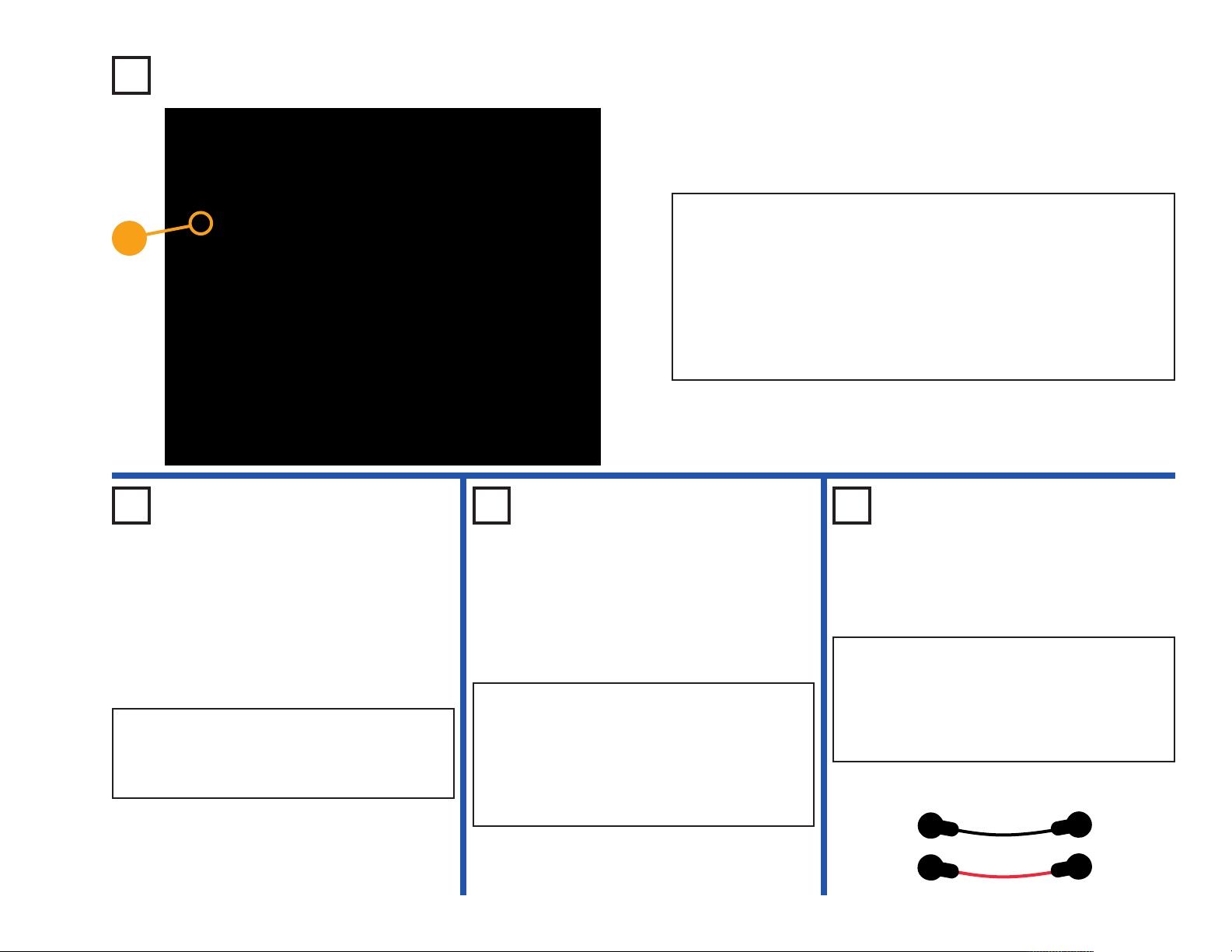
Page 10
Advanced Troubleshooting
(Adult supervision recommended)
ELENCO®is not responsible for parts
damaged due to incorrect wiring.
If you suspect you have damaged parts, you
can follow this procedure to systematically
determine which ones need replacing:
Note: Some of these tests connect an LED directly
across the batteries without another component
to limit the current. Normally this might damage
the LED, however, Circuit Maker LEDs have
internal resistors added to protect them from
incorrect wiring, and will not be damaged.
1. Red LED (D1), 4.5V lamp (L4), speaker
(SP2), and battery holder (B3): Place
batteries in holder. Place the red LED
directly across the battery holder (LED + to
battery +); it should light. Place the 4.5V
lamp directly across the battery holder, it
should light. “Tap” the speaker across the
battery holder contacts, you should hear
static as it touches. If none work, then
replace your batteries and repeat. If still bad,
then the battery holder is damaged.
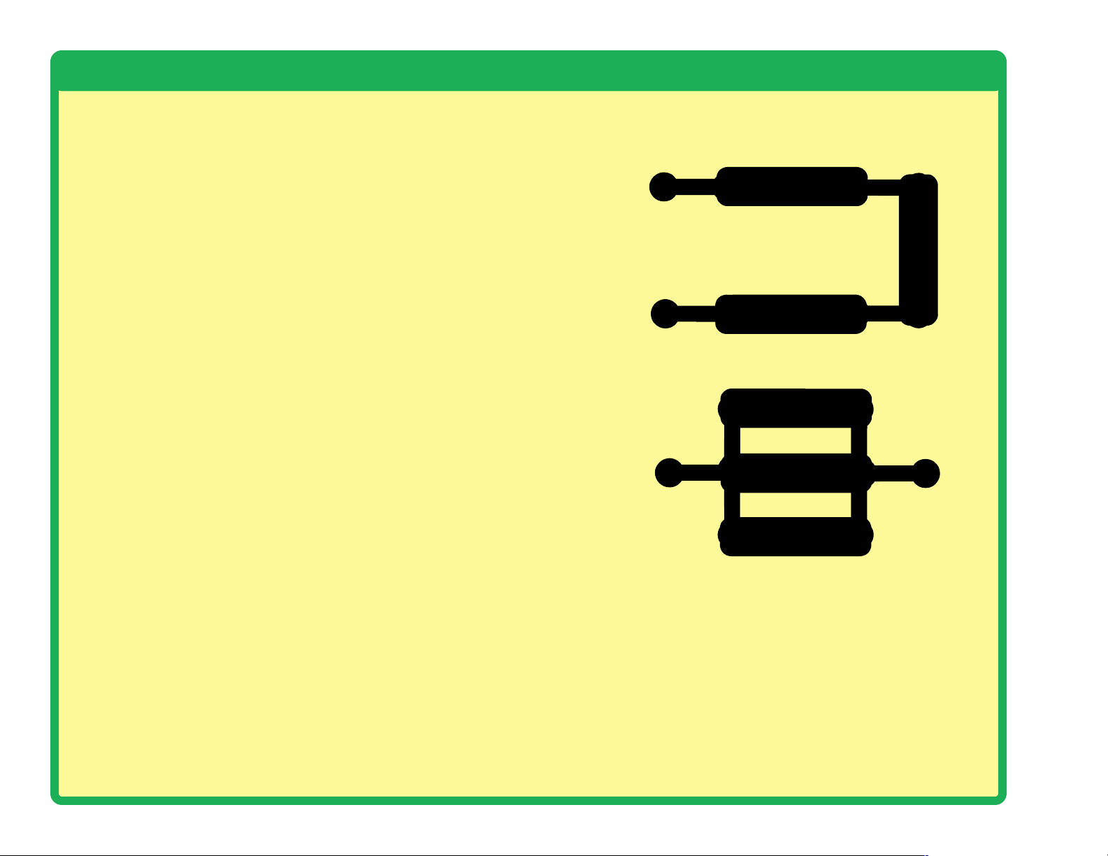
2. Jumper wires: Use this mini-circuit to test
each jumper wire, the lamp should light.
4. Slide switch (S1) and press switch (S2):
Build Project #1; if the lamp (L4) doesn’t light
then the slide switch is bad. Replace the
slide switch with the press switch to test it.
5.
100W (R1), 1KW (R2), and 5.1KW (R3)
resistors:
should be bright. If not, then R1 is damaged.
Next use the 1KW and 5.1KW resistors in
place of the 100W resistor; the LED should
be dimmer but still light.
6. Microphone (X1) and photoresistor (RP):
Build Project #13; if blowing into the
microphone does not change the LED (D1)
brightness then the microphone is bad.
Replace the microphone with the
photoresistor. Waving your hand over the
photoresistor (changing the light that shines
on it) should change the brightness of the
LED or the photoresistor is bad.
7. NPN transistor (Q2): Build the mini-circuit
shown here. The LED (D1) should only be
on if the press switch (S2) is pressed. If
otherwise, then the NPN is damaged.
1
Build Project #10; the red LED
9. Adjustable resistor (RV): Build Project
#14, the resistor control lever can turn the
LED (D1) on and off.
10. Recording IC (U6): Build Project #4.
Make an 8 second recording, then listen to
the three pre-recorded songs.
11. Space war IC (U3: Build Project #2, both
switches (S1 and S2) should change the
sound.
12. Whistle chip (WC): Build Project #165.
When you press the press switch (S2) you
should hear sound.
13. 100KW resistor (R5), 0.1mF (C2)
capacitor and 10mF capacitor (C3):
Build Project #120, it makes sound unless
the resistor is bad. Place the 0.1mF
capacitor on top of the whistle chip (WC)
and the sound changes (pitch is lower).
Replace the 0.1mF with the 10mF (“+” on
left) and the circuit will “click” about once
a second.
100mF (C4) capacitors: Build Project #75,
14.
press the press switch (S2) and turn on the
slide switch (S1). The LED (D1) should be
lit for about 5 seconds then go out (press
the press switch again to reset this).
3. Snap wires: Use this mini-circuit to test
each of the snap wires, one at a time. The
lamp should light.
-9-
8. PNP transistor (Q1): Build the mini-circuit
shown here. The LED (D1) should only be
on if the press switch (S2) is pressed. If
otherwise, then the PNP is damaged.
1
Customer Service
Call toll-free: (800) 533-2441
e-mail: help@elenco.com
Page 11

Project Listings
Project # Description Page #
1 Electric Light & Switch 12
2 Space War 12
3 Electronic Playground 13
4 Playback & Record 14
5 Light-Controlled Music 14
6 Touch-Controlled Music 14
7 Water Alarm 14
8 Fun with Sounds 15
9 Playground 15
10 Light Emitting Diode 16
11 Dim Light 16
12 Light Changing Light 16
13 Microphone Control 17
14 Conduction Detector 17
15 Adjustable Brightness 17
16 Red & White Control 18
17 Current Controllers 18
18 Touch Light 18
19 Speaker Static 18
20 Parallel Resistors 19
21 Series Resistors 19
22 Capacitors in Series 19
23 Capacitors in Parallel 19
24 Sound & Light in Series 20
25 Parallel Lamps 20
26 Light-Controlled LED 20
27 Two-Transistor Light Alarm 20
28 The Fuse 21
29 Sound by Rotary Switch 21
30 Quiet Zone Game 22
31 Music in the Light 22
32 This OR That 23
33 This AND That 23
34 Neither This NOR That 24
Project # Description Page #
35 NOT This AND That 24
36 Batteries in Series 25
37 Batteries in Series - LED 25
38 Diode 26
39 Musical Space War 26
40 Transistor Direction 27
41 Another Transistor Direction 27
42 Simple Rectifier 27
43 Slow Off Switch 28
44 Slower Off Switch 28
45 Current Control Q1 28
46 Current Control Q2 28
47 Reflection Detector 29
48 Quiet Reflection Detector 29
49 Make Your Own Battery 30
50 Make a Small Battery 30
51 Make Another Battery 30
52 Bomb Sound 30
53 Standard Transistor Circuit 31
54 Recharge Light 31
55 Transistor Amplifiers 32
56 Pressure Meter 32
57 Resistance Meter 32
58 NPN Amplifier 33
59 PNP Amplifier 33
60 PNP Collector 34
61 PNP Emitter 34
62 NPN Collector 34
63 NPN Emitter 34
64 NPN Light Control 35
65 NPN Dark Control 35
66 PNP Light Control 35
67 PNP Dark Control 35
68 Automatic Street Lamp 36
Project # Description Page #
69 Voice Control 36
70 Blowing Off the Electric Light 36
71 Listen to Your Breath 36
72 Light Alarm 37
73 Brighter Light Alarm 37
74 Light Dimmer 37
75 Auto-Off Night Light 38
76 Discharging Caps 38
77 Changing Delay Time 38
78 Two-Finger Touch Lamp 39
79 One-Finger Touch Lamp 39
80 Storing Electricity 40
81 Lamp Brightness Control 40
82 Motion Detector 41
83 LED Motion Detector 41
84 Whistling Recording IC 42
85 Two-Sound Output 42
86 Lights On & Off 42
87 Delayed Action Lamp 42
88 Watch Light 43
89 Adjustable Time Delay Lamp 43
90 Photo-Off Night Light 44
91 Sunrise Light 44
92 Capacitor Photo Control 45
93 Capacitor Control 45
94 Turn Off Timer 46
95 Turn Off Timer - Lamp 46
96 LED & Bulb Timer 46
97 LED & Bulb Short Timer 46
98 Slow Light Dimmer 47
99 Not-So-Slow Light 47
100 The SCR 47
101 Light-Controlled SCR 47
102 Adjustable Tone Generator 48
-10-
Page 12

Project Listings
Project # Description Page #
103 Photosensitive Electronic Organ 48
104 Electronic Cicada 48
105 Morse Code 49
106 Audio Morse Code 49
107 Dog Whistle 49
108 The Lie Detector 50
109 Clicking Liar 50
110 Slow Clicking Liar 50
111 Photo-Powered Recording 50
112 Photo Whistle Music 50
113 Whiner 51
114 Hummer 51
115 Adjustable Metronome 51
116 Quiet Flasher 51
117 Hissing Foghorn 52
118 Hissing & Clicking 52
119 Video Game Engine Sound 52
120 Tone Generator 53
121 Tone Generator (II) 53
122 Tone Generator (III) 53
123 More Tone Generator 53
124 More Tone Generator (II) 53
125 More Tone Generator (III) 53
126 Sound Wave Magic 54
127 Pitch 54
128 Photo Pitch 54
129 High Pitch Bell 55
130 Steamship 55
131 Water Alarm 55
132 Buzzing in the Dark 56
133 Touch Buzzer 56
134 High Frequency Touch Buzzer 56
135 High Frequency Water Buzzer 56
136 Mosquito 56
Project # Description Page #
137 Loud Mosquito 56
138 Oscillator 57
139 Pulse Oscillator 57
140 Whistle Oscillator 57
141 Flasher 57
142 Mail Notifying Electronic Lamp 58
143
144 Mail Notifying Mode Change 58
145 Lasting Doorbell 58
146 Lasting Clicking 58
147 Shorter Doorbell 58
148 Lighted Doorbell 58
149 Light Oscillator 59
150 Another Light Oscillator 59
151 Sound & Light Stepper Circuit 59
152 Another Light Oscillator 59
153 Transistor Power 60
154 Transistor Power (II) 60
155 Static Space Sounds 60
156 Blink & Beep 60
157 Blink & Beep (II) 60
158 Electricity You Can Wear 61
159 Electricity in Your Hair 61
160 Bending Water 62
161 Static Tricks 62
162 Recording LED Indicator 63
163 Pencil Alarm 63
164 Two Light Two Sounds 63
165 LED Music 64
166
167
168 Music AND Gate 65
169 Music OR Gate 65
170 Water Detector 66
Mail Notifying Electronic Lamp & Sound
Light-Controlled LED Time Delay
Touch-Controlled LED Time Delay
58
64
64
Project #
171 Saltwater Detector 66
172 Playback & Record with Light 67
173 Photo Music 67
174 Sliding Music 68
175 Synchronized Flasher 68
176 Slow Light Switcher 69
177 Space Battle 69
178 Space Battle (II) 69
179 Electronic Bombing Game 70
180 Photo Switcher 70
181 Blowing & Shining Lights 71
182 Adjustable Blowing Sound 71
183 Tunable Oscillator 72
184 High Low Oscillator 72
185 Recording IC 72
186 Whistle Recording 72
187 Mind Reading Game 73
188 Tap Start Recorder 74
189 Transistor Mic 74
190 Transistor Mic with Speaker 74
191 Adjustable Volume 75
192 Adjustable Volume Music 75
193 Adjustable Volume with Light 75
194 Audio Amplifier 76
195 Whistling Sound Amplifier 76
196 Whistle Amplifier 76
197 Blowing Audio Amplifier 76
198 Photo Audio Amplifier 76
199 Photo Whistle Amplifier 76
200 Air Audio Amplifier 77
201 Red LED Audio Amplifier 77
202 Whistle Chip Audio Amplifier 77
203 Photo Powered Music 77
Description Page #
-11-
Page 13
Placement
Level
Numbers
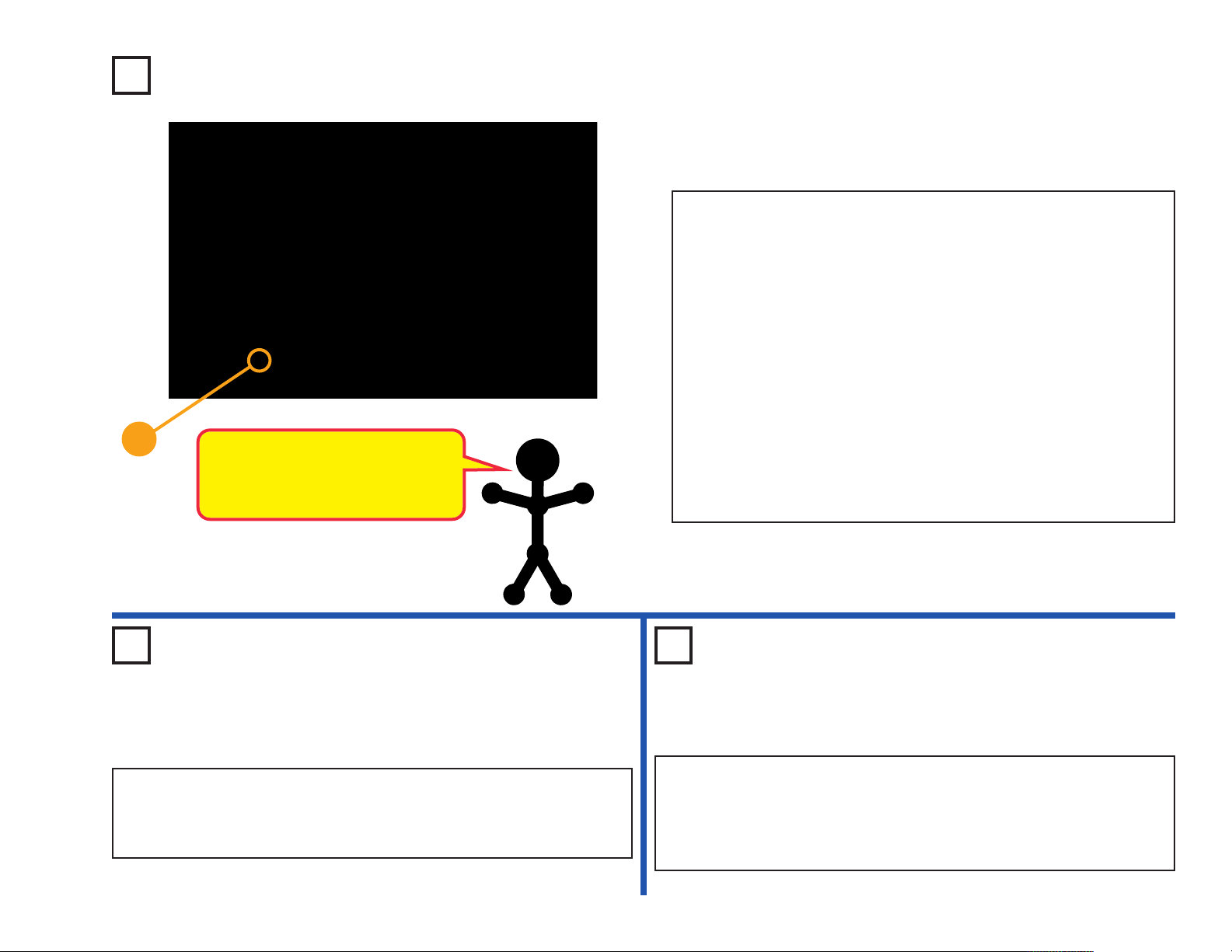
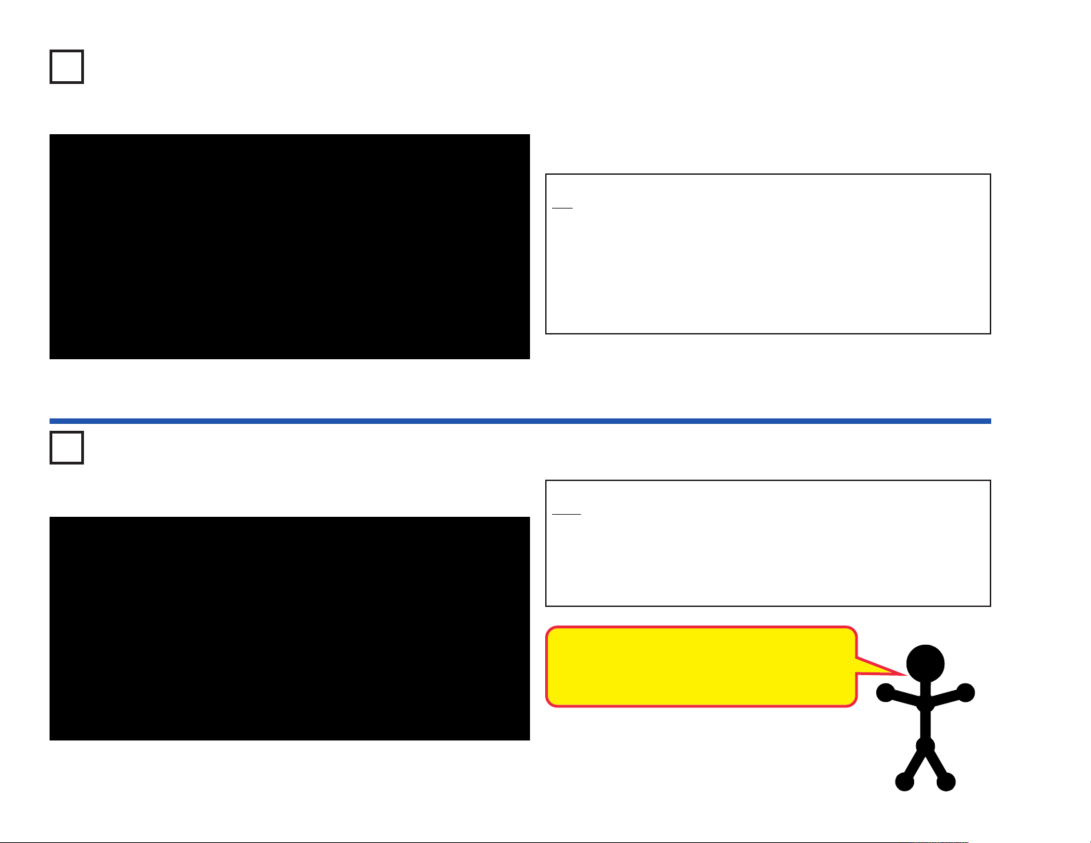
Project #1
Electric Light & Switch
Circuit Maker Sound Plus 200 uses electronic blocks that snap onto a
clear plastic grid to build different circuits. These blocks have different
colors and numbers on them so that you can easily identify them.
Build the circuit shown on the left by placing all the parts with a black 1
next to them on the board first. Then, assemble parts marked with a 2.
Install three (3) “AA” batteries (not included) into the battery holder (B3).
Turn on the slide switch (S1); the lamp (L4) lights.
When you close the slide switch (S1), current
flows from the batteries through the lamp and
back to the battery through the switch. The closed
switch completes the circuit. In electronics this is
called a closed circuit. When the switch is opened,
the current can no longer flow back to the battery,
so the lamp goes out. In electronics this is called
an open circuit.
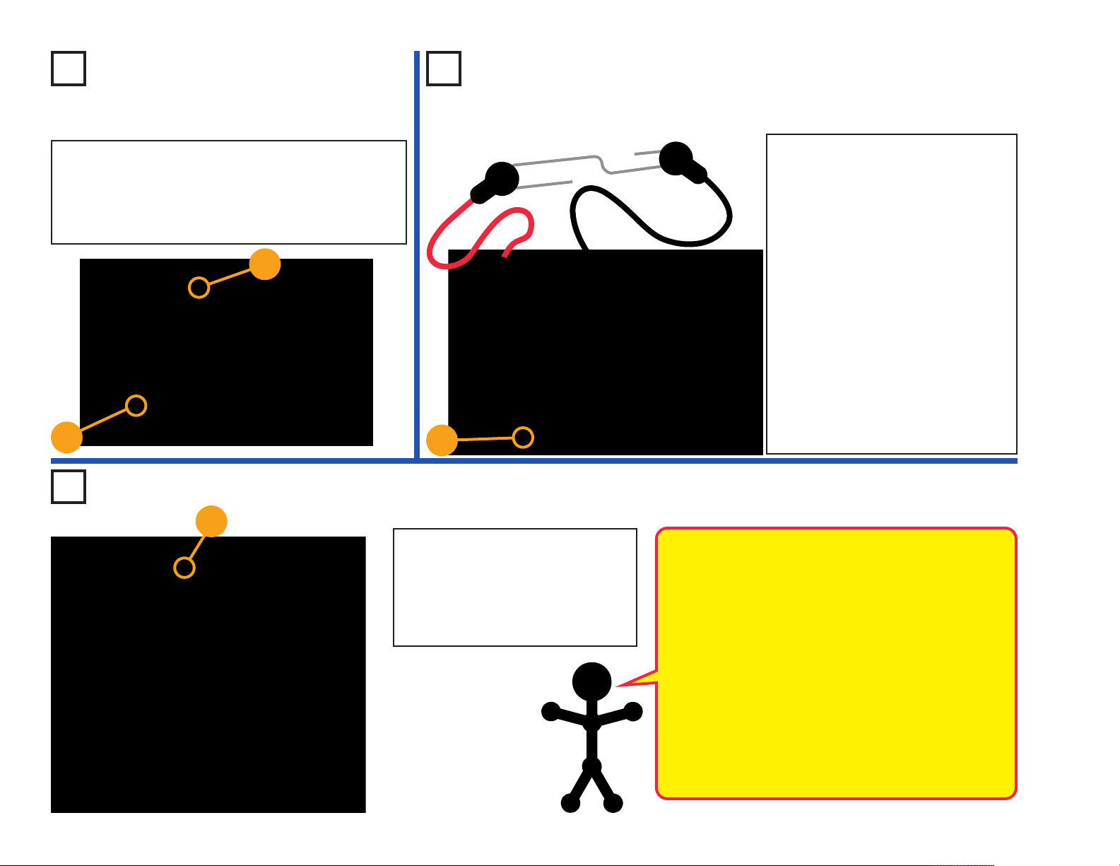
Project #2
Space War
Build the circuit shown on the left, which uses the space war integrated
circuit (U3). Activate it by flipping the slide switch (S1) or pressing the
press switch (S2); do both several times and in combination. You will
hear an exciting range of sounds, as if a space war is raging!
Like the other integrated circuits, the space war
IC is a super-miniaturized electronic circuit that
can play a variety of cool sounds stored in it by
using just a few extra components.
In movie studios, technicians are paid to insert
these sounds at the precise instant a gun is fired.
Try making your sound occur at the same time an
object hits the floor. It is not as easy as it sounds.
Placement Level
Numbers
-12-
Page 14
This complex circuit is
pictured on the box
cover, use that as a guide
to help in building it.
+
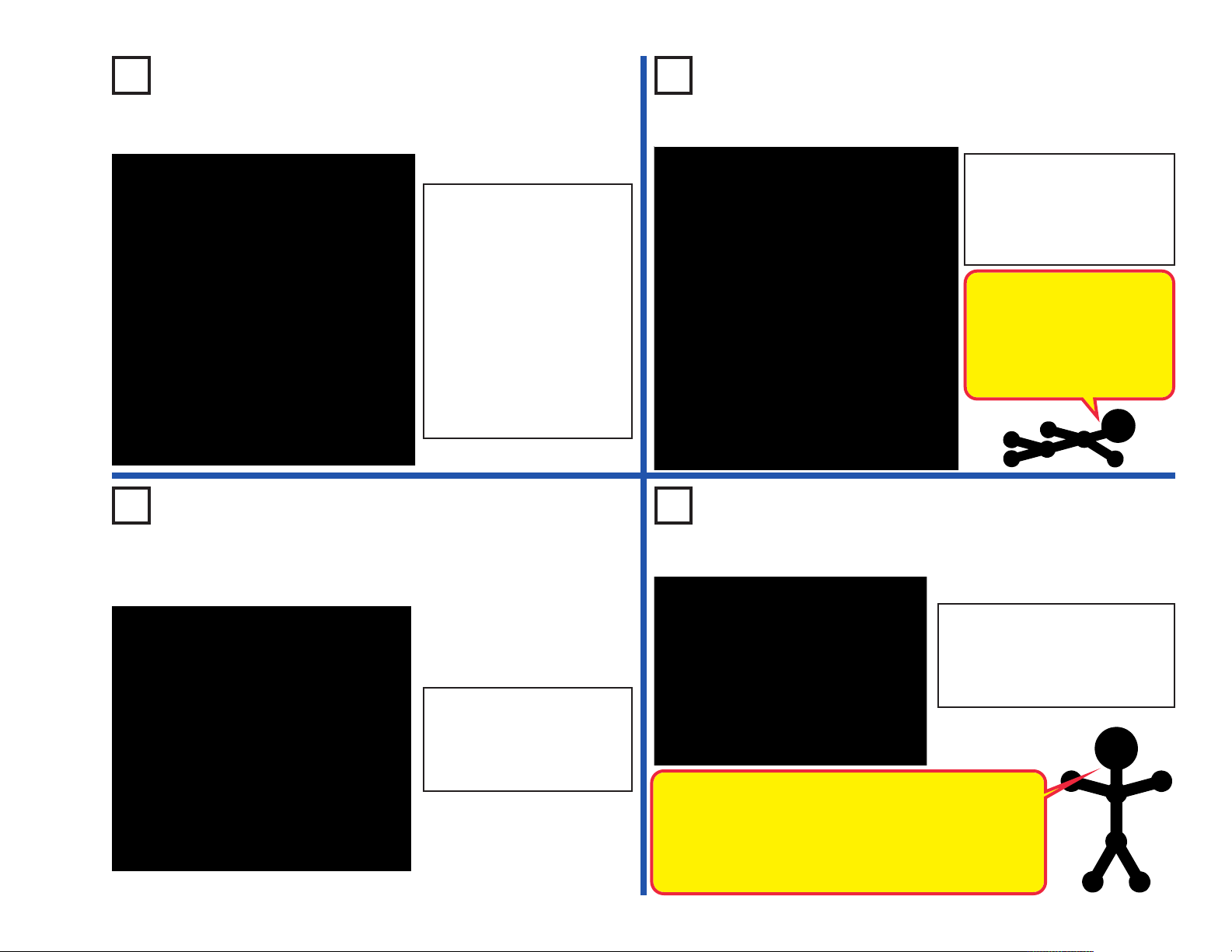
Project #3 Electronic Playground
Placement Level Numbers
+
+
Circuit Maker Sound Plus 200 uses electronic blocks that snap onto a clear
plastic grid to build different circuits. These blocks have different colors and
numbers on them so that you can easily identify them.
Build the circuit shown above by placing all the parts with a black 1 next to
them on the board first. Then, assemble parts marked with a 2. Then,
assemble parts marked with a 3. Install three (3) “AA” batteries (not included)
into the battery holder (B3).
If there is light on the photoresistor (RP) then you will hear a bomb sound.
Move the lever on the adjustable resistor (RV) to adjust the volume.
-13-
Placement
Level
Numbers
Push the press switch (S2) to play a recorded message followed by music,
press it again to stop the music. Move the lever on the adjustable resistor to
adjust the volume.
Turn on the slide switch (S1), you hear a beep signaling that you may begin
recording. Talk into the microphone (X1) up to 5 seconds, and then turn off
the slide switch (it also beeps after the 5 seconds expires).
The lamp (L4) will not light. The red LED (D1) will light at some settings on
RV.
Page 15
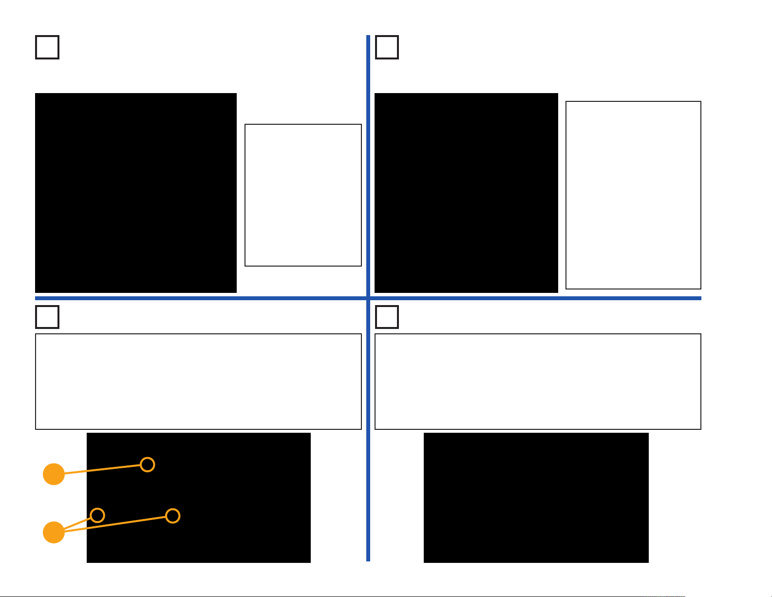
+
Project #4 Playback & Record
Build the circuit shown. Turn on the slide switch (S1), you hear a beep
signaling that you may begin recording. Talk into the microphone (X1)
up to 5 seconds, and then turn off the slide switch (it also beeps after
the 5 seconds expires).
Press the press switch (S2) for playback. It plays the recording you made
followed by one of three songs. If you press the press switch before the
song is over, music will stop. You may press the press switch several
times to play all three songs. The lamp (L4) is used to limit current and
will not light.
Project #5
Light-Controlled
Music
Use the circuit in Project #4. Replace the press
switch (S2) with the photoresistor (RP), then turn
on the slide switch (S1). Turn the music on and
off by waving your hand over the photoresistor.
Project #6
Touch-Controlled
Music
Use the circuit in Project #4. Place a single snap
on base grid point F1. Replace the press switch
(S2) with the PNP transistor (Q1, with the arrow
on point E2) and then turn on the slide switch
(S1). Turn the music on and off by touching
points F1 & G2 at the same time. You may need
to wet your fingers.
Project #7
Water Alarm
Use the circuit in Project #4. Make a new
recording warning that you detected water.
Remove the press switch (S2) and connect the
ends of the red and black jumper wires where it
had been. Place the other ends of the jumper
wires into a cup of water to activate your alarm.
-14-
Page 16

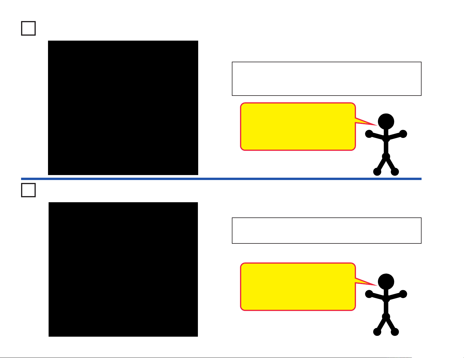
Project #8
Fun with Sounds
Uncover the photoresistor (RP) to play a recorded message
followed by music, cover it to stop the music.
Turn on the slide switch (S1), you hear a beep signaling that you
may begin recording. Talk into the microphone (X1) up to 5
seconds, and then turn off the slide switch (it also beeps after
the 5 seconds expires).
Push the press switch (S2) several times to make space war
sounds.
The red LED (D1) lights when there is sound. The lamp (L4) will
not light.
Project #9 Playground
-15-
Uncover the photoresistor (RP) to play a recorded message
followed by music, cover it to stop the music.
Turn on the slide switch (S1), you hear a beep signaling that you
may begin recording. Talk into the microphone (X1) up to 5
seconds, and then turn off the slide switch (it also beeps after
the 5 seconds expires).
Set the lever on the adjustable resistor (RV) to the right. Push
and release the press switch (S2); the red LED (D1) lights but
doesn’t goes out instantly. The lamp (L4) will not light.
If you swap the resistors (R1) and (R3) then the lamp will light,
but the recording quality will be worse.
Page 17
+
Project #10 Light Emitting Diode
LEDs use very little power and last
for thousands of hours. That’s why
they replaced the standard light bulb
in many products today.
Build the circuit shown on the left by placing all the parts with a black 1
next to them on the board first. Then, assemble parts marked with a 2.
When you close the slide switch (S1), current flows from the batteries
through the switch, through the resistor, through the LED (light emitting
diode) and back to the battery. The closed switch completes the circuit.
The resistor limits the current and prevents damage to the LED. NEVER
PLACE AN LED DIRECTLY ACROSS THE BATTERY! If no resistor is
in the circuit, the battery may push enough current through the LED to
damage the semiconductor that is used to produce the light. LEDs are
used in all types of electronic equipment to indicate conditions and pass
information to the user of that equipment.
Reverse the position of the LED (so the “+” is on the right) and turn on
the circuit - nothing happens. Since the LED is in backwards, current
cannot flow. The LED is like a check valve that lets current flow in only
one direction. Return the LED to the original position in the diagram.
Can you think of something you use every day that has an LED in it?
Project #11
Dim Light
Use the circuit from Project #10, but replace the 100W resistor (R1) with the
1KW resistor (R2). The LED is not as bright now because the resistance is
higher. Now replace the 1KW resistor (R2) with the 5.1KW resistor (R3). The
LED is even dimmer now because the resistance is even higher.
Project #12
Light Changing Light
Use the circuit from Project #10, but replace the 5.1KW resistor (R3) with
the photoresistor (RP). Vary the brightness of the LED by adjusting how
much light shines on the photoresistor.
The photoresistor changes its resistance depending on how much light
shines on it.
-16-
Page 18
Project #13
Project #14
Microphone Control
In this circuit, blowing on the microphone (X1) changes
the LED (D1) brightness.
The resistance of the microphone changes when you
blow on it. You can replace the microphone with one of
the resistors to see what resistor value it is closest to.
+
+
Project #15
+
Conduction Detector
+
Adjustable Brightness
In this circuit, changing the adjustable
resistor (RV) setting changes the
brightness of the LED (D1).
The lever on RV adjusts how much
resistive material the electric current
flows through.
Build the circuit, but leave the ends of the
red and black jumper wires unconnected at
first.
When you place a paper clip (not included)
across the loose ends of the jumper wires
as shown, current flows from the batteries
through the resistor, through the LED, and
back to the battery. The paper clip
completes the circuit and current flows
through the LED. Place your fingers across
the terminals and the LED does not light.
Your body is too high of a resistance to
allow enough current to flow to light the
LED. If the voltage, which is electrical
pressure, was higher, current could be
pushed through your fingers and the LED
would light. This detector can be used to
see if materials like plastic, wood, cloth,
aluminum, or paper are a good conductor
or a poor conductor.
Resistors are used to control or limit the flow of
electricity in a circuit. Higher resistor values reduce the
flow of electricity in a circuit.
In this circuit, the adjustable resistor is used to adjust
the LED brightness, to limit the current so the batteries
last longer, and to protect the LED from being damaged
by the batteries.
What is Resistance? Take your hands and rub them
together very fast. Your hands should feel warm. The
friction between your hands converts your effort into
heat. Resistance is the electrical friction between an
electric current and the material it is flowing through.
The adjustable resistor can be set for as low as 200W,
or as high as 50,000W (50kW).
-17-
Page 19
Project #16
Project #17
Red & White Control
Turn on the circuit using the
slide switch (S1) and/or the
press switch (S2) and move
the adjustable resistor’s (RV)
control lever around to adjust
the brightness of the D1 and
L4. When the adjustable
resistor is set to one side,
that side will have low
resistance and its light turns
(assuming the switch on that
side is ON) on while the
other is OFF.
Project #18
Touch Light
Current Controllers
Build the circuit and turn on the
slide switch (S1), the LED (D1) will
be lit. To increase the LED
brightness, turn on the press switch
(S2). To decrease the LED
brightness, turn off the slide switch.
With the slide switch on, the 1KW
resistor (R2) controls the current.
Turning on the press switch places the
100W resistor (R1) in parallel with it to
decrease the total circuit resistance.
Turning off the slide switch places the
5.1KW resistor (R3) in series with
R1/R2 to increase the total resistance.
Project #19
Speaker Static
Tap on the whistle chip and
the LED flickers. Tap again
and the LED may flicker for
a longer time. See how long
the LED will stay on.
Turn the slide switch (S1) on and
off several times. You hear static
from the speaker (SP2) when
you first turn on the switch, but
hear nothing after it is left on.
The speaker uses electromagnetism to create changes
in air pressure, which your ears feel and interpret as
sound. Think of the speaker as creating pressure waves
in the air just like waves in a pool. You only see waves
in the pool when you disturb the water, so the speaker
only makes sound when the voltage changes.
-18-
Page 20
Project #20
Project #21
Parallel Resistors
Turn on either or both
switches (S1 & S2) and
compare the LED (D1)
brightness.
This circuit has the 100W
resistor (R1) and 1KW
resistor (R2) arranged in
parallel. You can see that
the smaller 100W resistor
controls the brightness in
this arrangement.
Project #22 Capacitors in Series
Turn on the slide switch (S1), then press and release the press switch (S2). The
LED (D1) becomes bright when the 100mF capacitor (C4) charges up with the press
switch on, then the LED slowly gets dim after you release the press switch.
Now turn off the slide switch. Repeat the test with the slide switch off; you’ll notice
the LED goes out much faster after you release the press switch. The much smaller
10mF capacitor (C3) is now in series with the 100mF and so reduces the total
capacitance (electrical storage capacity), and they discharge much faster. (Note
that this is opposite to how resistors in series work).
Series Resistors
Turn on either or both
switches (S1 & S2) and
compare the LED (D1)
brightness.
This circuit has the 100W
resistor (R1), the 1KW resistor
(R2), and the photoresistor
(RP) arranged in series. You
can see that the larger
photoresistor controls the
brightness in this
arrangement (the resistance
of the photoresistor will be
much higher than the others,
unless the light is very bright).
Project #23 Capacitors in Parallel
Turn off the slide switch (S1), then press and release the press switch (S2). The
LED (D1) becomes bright when the 10mF capacitor (C3) charges up with the press
switch on, then the LED slowly gets dim after you release the press switch.
Now turn on the slide switch and repeat the test; you’ll notice the LED goes out
much slower after you release the press switch. The much larger 100mF capacitor
(C4) is now in parallel with the 10mF and so increases the total capacitance
(electrical storage capacity), and they discharge much slower. (Note that this is
opposite to how resistors in parallel work).
+
+
-19-
Page 21
Project #24
Project #25
Sound & Light in Series
Turn on the slide switch (S1) and the speaker sounds as the lamp (L4)
lights. The speaker and lamp are in series. The transistor is used to
increase the voltage on the lamp, otherwise it wouldn’t light
Project #26
Light-Controlled LED
Parallel Lamps
Turn on the slide switch
(S1) and the LED (D1) and
lamp (L4) light. If one of the
them is broken then the
other will still be on,
because they are in
parallel. An example of this
is most of the lights in your
house; if a bulb is broken on
one lamp then the other
lamps are not affected.
Project #27
Two-Transistor Light Alarm
When there is light on
the photoresistor (RP),
its resistance is low and
the LED (D1) will flicker.
Shield the photoresistor
from the light; the LED
should turn off.
Build the circuit with the
jumper connected as shown,
and turn it on. Nothing
happens. Break the jumper
connection and the lamp (L4)
turns on. You could replace
the jumper with a longer wire
and run it across a doorway to
signal an alarm when
someone enters.
-20-
Page 22

The FuseProject #28
Build the circuit shown. Pretend the 2-snap wire marked fuse in the
drawing on the left is a device that will open the circuit if too much current
is taken from the battery. With the slide switch (S1) turned on, remove
the 2-snap wire marked fuse and notice how the lamp (L4) shuts off. Until
the fuse is replaced, the open circuit path protects the electronic parts.
If fuses did not exist, many parts could get hot and even start fires.
Replace the 2-snap wire and the lamp should light again.
Some fuses contain special wires that break when too much current
flows, and need to be replaced after they activate. Other fuses can be
reset by flipping a switch.
Many electronic products in your home have a fuse that will open when
too much current is drawn. Can you name some?
Actual fuse - if too much current flows then the
wire inside melts to break the circuit.
-21-
Project #29
Sound by
Rotary Switch
Place the 3-snap as shown and turn the switch (S1) on. There should
be no sound since the 3-snap is not touching point A or B. Now rotate
the 3-snap to points A or B and the speaker sounds.
Today most device use electric switches. Until the early 1970s,
mechanical switches were used as channel selectors on television and
other electronic equipment.
Page 23
Sheet of paper
to hide position
of shorting bar
Shorting Bar for
A, B, C, or D
Project #30
Quiet Zone Game
Shorting Bar for W, X, Y, or Z
Build the circuit on the left. It uses both jumper wires as
permanent connections. It also uses three (3) 2-snap wires
(“shorting bars”) under paper as shown.
Setup: Player 1 sets the “Quiet Zone” by placing three (3)
shorting bars under the paper on row A, B, C, or D, leaving only
one open. Player 2 must NOT know where the shorting bars are
located under the paper.
Both Player 1 and Player 2 are given 10 points. The object is for
Player 2 to guess the location of the “Quiet Zone” by placing their
shorting bar at positions W, X, Y, or Z. In the drawing on the left,
Player 1 sets up the “Quiet Zone” at position “C”. If Player 2
places their shorting bar across “Z” on the first try, the sounds
played mean they have not found the “Quiet Zone” and they lose
1 point. They have 4 tries to find the zone on each turn. Each
time sounds are made, they lose a point.
Player 2 then sets the A, B, C, D side and Player 1 starts
searching. Play continues until one player is at zero points and
makes sound during that player’s turn.
Project #31
Music in the Light
Press the press switch (S2) to play a recording followed by a song. If
you press the press switch before the song is over, music will stop. Adjust
the amount of light on the photoresistor (RP) to change the volume and
alter the tone. Wave your fingers over the photoresistor for some cool
sound effects.
-22-
Page 24
Project #32
This OR That
Build the circuit shown. Notice that if you turn on the slide switch (S1)
OR press the press switch (S2) the LED (D1) lights up. There is no
partially lit state here, the diode is either totally on or totally off. While
this may seem very simple and boring, it represents an important
concept in electronics. Two switches like this may be used to turn on a
light in your house, or they might be two sensors at a railroad crossing
used to start the ding-ding sound and lower the gate. You could also
have more than two switches and the circuit would function the same
way.
-23-
Project #33
This AND That
Build the circuit shown. Notice that if you turn on the slide switch (S1)
AND press the press switch (S2) the LED (D1) lights up. Once again,
there is no partially lit state here, the LED is either totally on or totally
off. Two switches like this may be used to turn on the same light in your
house, the room switch and the master switch in the electrical box. You
could also have more than two switches and the circuit would function
the same way.
Combinations of AND and OR circuits are used
to add and multiply numbers together in modern
computers. These circuits are made of tiny
transistors in massive integrated circuits.
Page 25

Project #34
Neither This NOR That
Build the circuit at left and test the combinations of the slide switch (S1)
and press switch (S2). If you compare it to the OR circuit in Project #32,
you can see the LED (D1) lights in the opposite combinations of that
circuit. Hence, we refer to it as a NOR
that”). Like the OR and AND, it is an important building block in
computers.
circuit (short for “NOT this OR
Project #35
NOT This AND That
Build the circuit at left and test the combinations of the slide switch (S1)
and press switch (S2). If you compare it to the AND circuit in Project #33,
you can see the LED (D1) lights in the opposite combinations of that
circuit. Hence, we refer to it as a NAND
that”). This circuit can also have more or less than two inputs, though
when it only has one input it is referred to as a NOT circuit. Like the OR,
AND, and NOR, NAND and NOT are important building blocks in
computers.
circuit (short for “NOT this AND
-24-
Page 26

Part A
Project #36
Part B
Part C
Batteries in Series
Build the circuit and connect the black jumper wire as shown in Part A.
The lamp (L4) is bright because it is powered by three (3) 1.5V “AA”
batteries (4.5V total).
Remove the right battery from the holder (B3) and move the end of the
black wire to touch the right contact point in the holder as shown in Part
B. The lamp is not as bright because now it is only powered by 2
batteries (3V total).
Now also remove the center battery from the holder and move the end
of the black wire to touch the center contact point in the holder as shown
in Part C. The lamp is dim because now it is only powered by 1 battery
(1.5V total).
The batteries in the holder are connected in series to give a higher total
voltage.
-25-
Part A
Project #37
Part B
Part C
Batteries in Series -
LED
Build the circuit and connect the black jumper wire as shown in Part A.
The red LED (D1) is bright because it is powered by three (3) 1.5V “AA”
batteries (4.5V total).
Remove the right battery from the holder (B3) and move the end of the
red wire to touch the right contact point in the holder as shown in Part B.
The red LED is just about as bright because 2 batteries (3V total) give it
enough voltage to work properly.
Now also remove the center battery from the holder and move the end
of the red wire to touch the center contact point in the holder as shown
in Part C. The red LED is dim.
Compare how the LED works here to how the lamp worked in the
preceding project.
Page 27

Project #38
Diode
Diodes are electronic components that allow current to flow in only one
direction, blocking it in the other. The red LED (D1) are special diodes
that can emit light, and the transistors (Q1 & Q2) can also be used as
diodes.
Turn on the slide switch (S1), the lamp (L4) will be bright and the LED
(D1) will be lit. The NPN transistor (Q2) is used here as a diode, allowing
the batteries to charge up the 100mF capacitor (C4) and light the LED.
Turn off the slide switch, the lamp will go dark immediately but the LED
will stay lit for a few moments as capacitor C4 discharges through it. The
transistor/diode isolates the capacitor from the lamp; if you bypass the
transistor by placing a 3-snap wire over it (on level 4 across base grid
locations B2-B4) then the lamp will drain the capacitor almost instantly.
Project #39
Musical Space War
Turn on the slide switch (S1) and you hear space war sounds as the LED
(D1) flashes. If you wave your hand over the photoresistor (RP), the
sound changes. If you keep the photoresistor covered, then the sound
will stop.
Press the press switch (S2) and you will hear music in addition to any
space war sounds that are playing. Press the press switch again to
change the music. You will also hear any recording you had made
previously with other projects.
-26-
Page 28

Project #40
Project #41
Transistor Direction
The press switch (S2) controls the
NPN transistor (Q2) and can turn
on the lamp. The slide switch
(S1), however, cannot control the
PNP transistor (Q1) and so
cannot turn on the lamp.
The two transistors are installed
the same way in the circuit but
work differently - current can
only flow in the direction of the
arrow marked on the part.
Project #42
Another Transistor
Direction
This circuit is similar
to the preceding one
except for the way
the transistors are
connected.
Now the press switch
(S2) cannot control the
NPN transistor (Q2)
and so cannot turn on
the lamp. The slide
switch (S1), however,
can control the PNP
transistor (Q1) and so
does turn on the lamp.
Simple Rectifier
Turn on the slide switch (S1) and the LED (D1) lights; it will not be very
bright so turn off the room lights or hold your fingers around it to see it
better. Press the press switch (S2) several times very slowly; the LED
and lamp (L4) go on and off.
Press the press switch many times quickly - the lamp still goes on and
off but the LED stays on. Next, remove the 100mF capacitor (C4) from
the circuit - the LED goes on and off now. Why?
Pressing the switch quickly simulates a changing voltage, which turns
the LED on and off. The 100mF capacitor can store electricity, and it
combines with the NPN transistor (Q2) to simulate a rectifier. This rectifier
converts the changing voltage at the press switch into a constant voltage,
which keeps the LED on.
The electricity supplied to your home by your electric company is actually
a changing voltage. Many electronic products use rectifier circuits to
convert this into a constant voltage like a battery provides.
-27-
Page 29

Project #43
Slow Off Switch
Project #44
Slower Off
Build the circuit, turn on the slide switch
(S1), and press the press switch (S2). You
see that the LED (D1) doesn’t turn off
immediately after you release the switch. If
you remove the capacitor from the circuit by
turning off the slide switch, then the LED
goes off immediately.
This delay in turning off the LED is caused
by the 100mF capacitor (C4). Capacitors
can store electricity and are used to delay
changes in voltage. They can block
unchanging voltages while passing fastchanging voltages.
Project #45
Current Control Q1
Turn on the slide switch (S1), the LED (D1) and lamp (L4) are bright. This is an
unusual circuit which uses the PNP transistor (Q1) as two connected diodes to split
the current from the batteries (B3) into the paths with the LED and lamp.
Switch
Change the 1KW resistor (R2) to the
5.1KW resistor (R3). Now the LED (D1)
is dimmer but stays on longer.
Project #46
Current Control Q2
Transistors use a small current to control a
large current, and have three connection
points (the small current, the larger current,
and the combined current). But they are
actually constructed using two diodes that
are connected together. These diodes are
similar to your LED (light emitting diode)
except that they don’t emit light.
This circuit is just like
the preceding one but it
uses the NPN
transistor (Q2). The
transistor connections
are opposite to the
NPN transistor (Q2),
but otherwise the circuit
works the same way.
-28-
Page 30

Project #47
Reflection Detector
Build the circuit on the left. Place it where there won’t be any room light
hitting the photoresistor (RP) (such as in a dark room or under a table),
and then turn it on. The 4.5V lamp (L4) will be bright but there should be
no sound.
Reset the circuit by turning the slide switch (S1) off and back on. Take a
small mirror and hold it over the lamp and photoresistor. You should hear
sound now as the mirror reflects light from the lamp onto the
photoresistor. You have a reflection detector!
The photoresistor is used as a switch here to turn on music from the
recording IC (U6).
-29-
Project #48
Quiet Reflection Detector
Let’s modify the reflection detector circuit so that it is not so loud. We’ll
also put a light on it that can be seen in a noisy room. Build the circuit on
the left. Place it somewhere where there won’t be any room light hitting
the photoresistor (RP) (such as in a dark room or under a table), and
then turn it on. The 4.5V lamp (L4) will be bright but there should be little
or no sound.
Take a small mirror and hold it over the lamp and photoresistor. You
should hear a more faint sound and the LED (D1) should light now as
the mirror reflects light from the lamp onto the photoresistor.
Page 31

Project #49
Make Your Own
Project #50
Project #51
Make
Battery
Build the circuit, then connect points Y & Z (use a 2-snap
wire) for a moment. Nothing appears to happen, but you
just filled up the 100mF capacitor (C4) with electricity.
Now disconnect Y & Z and instead touch a connection
between X & Y. The red LED (D1) will be lit and then go
out after a few seconds as the electricity you stored in it
is discharged through the LED and resistor (R2).
Notice that a capacitor is not very
efficient at storing electricity - compare
how long the 100mF kept the LED lit for
with how your batteries run all of your
projects! That is because a capacitor
stores electrical energy while a battery
stores chemical energy.
Make a Small
Battery
In the preceding circuit, replace the 100mF
capacitor (C4) with the 10mF capacitor (C3)
and repeat the test. You see that the LED
(D1) only lights for a moment, because the
10mF capacitor does not store as much
electricity as the 100mF.
The 0.1mF capacitor (C2) stores very little
electricity, so if you replace the 10mF capacitor
with it then the LED will not light at all.
Project #52 Bomb Sound
Another
Battery
Place the 100mF capacitor (C4) back into
the circuit. Now replace the 1KW resistor
(R2) with the 100W resistor (R1) and try it.
The LED (D1) gets brighter but goes out
faster because less resistance allows the
stored electricity to dissipate faster.
You can also change the resistor to the
5.1KW resistor (R3). The LED will be
dimmer but stay on longer.
Turn the switch (S1) on and you
hear the sound of a bomb
dropping and then exploding. The
LED (D1) lights and then flashes
as the bomb explodes. This is one
sound generated from the space
war IC (U3).
-30-
Page 32
Project #53
Standard
Transistor Circuit
Turn on the slide switch (S1) and move the adjustable resistor (RV)
control lever across its range. When the lever is all the way down the
LED (D1) will be off, as you move the lever up it will come on and reach
full brightness.
This circuit is considered the standard
transistor configuration for amplifiers. The
adjustable resistor control will normally be
set so that the LED is at half brightness,
since this minimizes distortion of the signal
being amplified.
Project #54 Recharge Light
-31-
Press the press switch (S2) and the lamp (L4) will be on for a few
moments. Wait 5-10 seconds before pressing the switch again, or
nothing will happen.
Pressing the switch charges up the 100mF
capacitor (C4) turning on transistors Q1
and Q2, and the lamp (L4) lights. Once C4
is charged up, the voltage at Q1 drops and
it turns the lamp off. You must wait until C4
discharges to turn the lamp on again.
Page 33

Project #55 Transistor Amplifiers
When you place one or more fingers across the two snaps marked X &
Y you will notice the LED (D1) turns on. The two transistors are being
used to amplify the very tiny current going through your body to turn on
the LED. Transistors are actually electrical current amplifiers. The PNP
transistor (Q1) has the arrow pointing into the transistor body. The NPN
transistor (Q2) has the arrow pointing out of the transistor body. The PNP
amplifies the current from your fingers first, then the NPN amplifies it
more to turn on the LED.
Project #56
Pressure Meter
Use the circuit from Project #55 shown above.
When you placed your fingers across the two snaps marked X & Y you
noticed the LED (D1) came on in Project #55. Repeat this process, but this
time press very lightly on the two snaps marked X & Y. Notice how the
brightness of the LED is dependent on the amount of pressure you use.
Pressing hard makes the LED bright while pressing very gently makes it
dim or even flash. This is due to what technicians call “contact resistance”.
Even switches made to turn your lights on and off have some resistance in
them. When large currents flow, this resistance will drop the voltage and
produce the undesirable side effect of heat.
Project #57
Resistance Meter
Use the circuit from Project #55 shown above.
When you placed your fingers across the two snaps marked X & Y you
noticed the LED (D1) came on in Project #55. In this project, you will place
different resistors across R & Z and see how bright the LED glows. Do not
snap them in; just press them up against the snaps labeled R & Z in the
diagram above.
First, place the 100KW resistor (R5) across the R & Z snaps and note the
brightness of the LED. Next, press the 5.1kW resistor (R3) across R & Z.
Notice how the LED gets brighter when the resistance is less. This is
because the NPN amplifier (Q2) gets more current at its input when the
resistance is lower. The PNP amplifier (Q1) is not used in this test.
-32-
Page 34

Project #58
NPN Amplifier
There are three connection points on an NPN transistor (Q2), called base
(marked B), emitter (marked E), and collector (marked C). When a small
electric current flows from the base to the emitter, a larger (amplified)
current will flow from the collector to the emitter. Build the circuit and
slowly move up the adjustable resistor (RV) control. When the LED (D1)
becomes bright, the lamp (L4) will also turn on and will be much brighter.
-33-
Project #59
PNP Amplifier
The PNP transistor (Q1) is similar to the NPN transistor (Q2) in the
preceding project, except that the electric currents flow in the opposite
directions. When a small electric current flows from the emitter to the
base, a larger (amplified) current will flow from the emitter to the collector.
Build the circuit and slowly move up the adjustable resistor (RV) control.
When the LED (D1) becomes bright, the lamp (L4) will also turn on and
will be much brighter.
Page 35

Project #60 PNP Collector Project #61
PNP Emitter
Build the circuit and vary the
lamp (L4) brightness with
the adjustable resistor (RV),
it will be off for most of the
resistor’s range. The point
on the PNP (Q1) that the
lamp is connected to (point
E3 on the base grid) is
called the collector, hence
the name for this project.
Project #62 NPN Collector
Compare this circuit to that in
Project #60, it is the NPN
transistor (Q2) version and
works the same way. Which
circuit makes the lamp (L4)
brighter? (They are about the
same because both transistors
are made from the same
materials).
Project #63
Compare this circuit to that in
Project #60. The maximum
lamp (L4) brightness is less
here because the lamp
resistance reduces the emitterbase current, which controls
the emitter-collector current.
The point on the PNP (Q1) that
the lamp is now connected to
(grid point C3) is called the
emitter.
NPN Emitter
Compare this circuit to that in
Project #61. It is the NPN
transistor (Q2) version and
works the same way. The
same principles apply here as
in Projects #60-#62, so you
should expect it to be less
bright than Project #62 but as
bright as Project #61.
-34-
Page 36
Project #64
Project #65
NPN Light Control
Turn on the slide switch (S1),
the brightness of the LED (D1)
depends on how much light
shines on the photoresistor
(RP). The resistance drops as
more light shines, allowing
more current to the NPN (Q2).
Project #66
PNP Light Control
NPN Dark Control
Turn on the slide switch (S1),
the brightness of the LED (D1)
depends on how LITTLE light
shines on the photoresistor
(RP). The resistance drops as
more light shines, diverting
current away from the NPN
(Q2).
Project #67
PNP Dark Control
-35-
Turn on the slide switch (S1),
the brightness of the LED (D1)
depends on how much light
shines on the photoresistor
(RP).
The resistance drops as more
light shines, allowing more
current through the PNP (Q1).
This is similar to the NPN (Q2)
circuit above.
Turn on the slide switch (S1),
the brightness of the LED (D1)
depends on how LITTLE light
shines on the photoresistor
(RP). The resistance drops as
more light shines, so more
current gets to the 100kW
resistor (R5) from the
photoresistor path and less
from the PNP-diode path. This
is similar to the NPN circuit
above.
Page 37

Project #68
Automatic
Project #69
Street Lamp
Press the press switch (S2) on and set
the adjustable resistor (RV) so the lamp
(L4) just lights. Slowly cover the
photoresistor (RP) and the lamp
brightens. If you place more light at the
photoresistor the light dims.
This is an automatic street lamp that
you can turn on by a certain darkness
and turn off by a certain brightness.
This type of circuit is installed on many
outside lights and forces them to turn
off and save electricity. They also come
on when needed for safety.
Turn the slide switch (S1) on and there should be no sound.
The transistor is on so the voltage on U3 is low. Blowing on
the microphone (X1) turns transistor (Q2) off, the voltage on
U3 voltage goes high and the speaker will sounds.
Voice Control
Project #70 Blowing Off the Electric Light
Install the parts. The lamp (L4) will
be on. It will be off as long as you
blow on the microphone (X1).
Speaking loud into the mic will
change the brightness of the lamp.
Project #71
Listen to
Your Breath
The microphone is a resistor
that changes in value due to
the changes in air pressure on
its surface.
Modify the circuit in the preceding
project by replacing the lamp (L4)
with the speaker (SP2). Blow into
the microphone and hear it in the
speaker.
Talk directly into the microphone.
You can hear your voice on the
speaker, though it may be badly
distorted.
-36-
Page 38

Project #72 Light Alarm
Build the circuit with the jumper connected as
shown, and turn it on. Nothing happens. Break the
jumper connection and the light turns on. You could
replace the jumper with a longer wire and run it
across a doorway to signal an alarm when someone
enters.
Project #73
Brighter
Light Alarm
Modify the circuit in the preceding project
by replacing the LED (D1) with the 4.5V
lamp (L4) and replacing the 5.1KW resistor
(R3) with the 100W resistor (R1). It works
the same way but is brighter now.
-37-
Project #74
+
Light Dimmer
Press the press switch (S2) to complete the current’s path flow. You
might expect the LED (D1) to light instantly but it doesn’t. The charging
current flows into the 100mF capacitor (C4) first. As the capacitor
charges, the charging current decreases, input current to the PNP
transistor (Q1) increases. So current begins to flow to the LED and the
LED gradually brightens.
Now release the press switch. The capacitor begins to discharge,
sending input current to the transistor. As the capacitor discharges, the
input current reduces to zero and gradually turns off the LED and the
transistor.
Page 39

Project #75 Auto-Off Night Light
When you turn on the slide switch (S1) the first time the LED (D1) will
come on and very slowly get dimmer and dimmer. If you turn the slide
switch (S1) off and back on after the light goes out it will NOT come on
again. The 100mF capacitor (C4) has charged up and the NPN transistor
amplifier (Q2) can get no current at its input to turn it on.
This circuit would make a good night-light. It would allow you to get into
bed, and then it would go out. No further current is taken from the battery
so it will not drain the batteries (B3) even if left on all night.
Project #76
Discharging Caps
Use the circuit from Project #75 shown above.
When you first turned on the slide switch (S1) in Project #75, the LED (D1)
came on and very slowly got dimmer and dimmer. When you turned the
slide switch (S1) off and back on after the light went out, it did NOT come
on again. The 100mF capacitor (C4) was charged and everything stopped.
This time turn the slide switch off. Then press the press switch (S2) for a
moment to discharge the 100mF capacitor. Now when you turn the slide
switch back on the delay repeats. Shorting a capacitor with a low resistance
will allow the charges on the capacitor to leave through the resistance. In
this case, the low resistance was the press switch.
Project #77
Changing Delay Time
Use the circuit from Project #75 shown above.
Change the 100mF capacitor (C4) to the 10mF capacitor (C3). Make sure
the capacitor (C3) is fully discharged by pressing the press switch (S2)
before closing the on-off slide switch (S1). When slide switch is turned on,
notice how much quicker the LED (D1) goes out. Since 10mF is smaller
than 100mF, the LED will go out faster. The bigger the capacitor the longer
the delay.
In electronics, capacitors are used in every piece of equipment to delay
signals or tune circuits to a desired frequency.
-38-
Page 40

Project #78
Two-Finger Touch Lamp
Build the circuit on the left. You’re probably wondering how it can work,
since one of the points on the NPN transistor (Q2) is unconnected. It
can’t, but there is another component that isn’t shown. That component
is you.
Touch points X & Y with your fingers. The LED (D1) may be dimly lit. The
problem is your fingers aren’t making a good enough electrical contact
with the metal. Wet your fingers with water or saliva and touch the points
again. The LED should be very bright now. Think of this circuit as a touch
lamp since when you touch it, the LED lights. You may have seen such
a lamp in the store or already have one in your home.
-39-
Project #79
One-Finger Touch Lamp
The touch lamps you see in stores only need to be touched by one finger
to light, not two. So let’s see if we can improve the last circuit to only
need one finger. Build the new circuit, note that near point X there is a
2-snap wire that is only mounted on one side, swing it so the plastic
touches point X. Wet a large area of one of your fingers and touch it to
both metal contacts at point X at the same time; the LED (D1) lights. To
make it easier for one finger to touch the two contacts, touch lamps or
other touch devices will have the metal contacts interweaved as shown
below and will also be more sensitive so that you don’t have to wet your
finger to make good contact.
Page 41

Project #80 Storing Electricity
Turn the slide switch (S1) on and connect points A & B with a 2-snap
wire. The red LED (D1) will flash and the 100mF capacitor (C4) will be
charged with electricity. The electricity is now stored in the capacitor.
Disconnect points A & B. Connect points B & C and there will be a flash
from the 4.5V lamp (L4).
The capacitor discharges through the resistor to the
base of the NPN transistor (Q2). The positive current
turns on the transistor like a switch, connecting the
lamp to the negative (–) side of the batteries. The
light will go out after the capacitor discharges,
because there is no more current at the base of the
transistor.
Project #81
Lamp Brightness
Control
Here is a combination with two transistors. This combination increases
the amplifying power. By changing the resistance, the current at the base
of the transistor is also changed. With this amplifying ability of the
combination, there is a greater change of current to the 4.5V lamp (L4).
This changes the brightness.
-40-
Page 42

Project #82
Motion Detector
Place this circuit near a bright light. Turn the slide switch (S1) on and
move the adjustable resistor (RV) control all the way up. The brightness
of the lamp (L4) is at maximum. Now, move the adjustable resistor
control down until the lamp goes out. Set the control up a little and the
lamp lights dimly.
Move your hand from side to side over the photoresistor (RP). As your
hand blocks the light, the lamp goes out.
Wave your hand over the photoresistor (RP) and the lamp turns off and
on. The resistance changes as the amount of light strikes the
photoresistor. As the light decreases, the resistance increases. The
increased resistance lowers the voltage at the base of the NPN transistor
(Q2). This turns off the transistor, preventing current flowing through the
lamp to the negative (–) side of the battery (B3). Wave your hand over
the photoresistor at different distances. The lamp gets brighter the farther
away your hand is.
-41-
Project #83
LED Motion Detector
The amount of light changes the resistance of the photoresistor and the
current flow to the base of the NPN transistor (Q2). The transistor acts like
a switch. Its base current is supplied through the photoresistor. As the base
current changes, so does the current flow through the LED. With no base
current, the LED goes out.
There are many applications for the use of the
detector. The most common is in the alarm system
industry. Some other applications are automatic
door openers, light switches in hallways, stairways
and areas that increase safety for the public.
Page 43

Project #84
Project #85
Whistling Recording IC
Build the circuit shown. Turn on
the slide switch (S1), you hear a
beep signaling that you may begin
recording. Talk into the microphone (X1) up to 5 seconds, and
then turn off the slide switch (it
also beeps after the 5 seconds
expires). Press the press switch
(S2) for playback. It plays the
recording you made followed by
one of three songs. If you press
the press switch before the song
is over, music will stop. You may
press the press switch several
times to play all three songs.
Project #87
Delayed Action Lamp
Two-Sound Output
Use the preceding circuit, but replace the 3-snap
at base grid locations E6-G6 with the speaker
(SP2) and place the red LED (D1) over the 100W
resistor (R1). It will be across base grid locations
A6-C6 on level 4, with its “+” side on top (at A6).
Project #86
Lights On & Off
Use the preceding circuit, but place the red LED
(D1) over the NPN transistor. It will be across
base grid locations C6-E6 on level 4.
Turn on the slide switch (S1) and press the press switch (S2). The lamp
(L4) turns on slowly, but stays on for a while after you release the press
switch.
-42-
Page 44

Project #88
Watch Light
Turn on the switch and press the press switch (S2). The lamp (L4) stays
on for a few seconds after you release the press switch.
A miniature version of a circuit like this might be in your wristwatch - when
you press a light button on the watch to read the time in the dark, a light
comes on but automatically turns off after a few seconds to avoid
draining the battery.
-43-
Project #89
Adjustable
Time Delay Lamp
Turn on the switch and press the press switch (S2). The lamp (L4) stays
on for a few seconds after you release the press switch. You can change
the delay time with the adjustable resistor (RV).
Page 45
Project #90
Photo-Off Night Light
Cover the photoresistor (RP) and turn on the slide switch (S1). The LED
(D1) is bright, but it will very slowly get dimmer and dimmer as the 100mF
capacitor (C4) charges up. If you turn the slide switch off and back on
after the light goes out, it will NOT come on again. Press the press switch
(S2) to discharge the capacitor and reset the circuit.
If you uncover the photoresistor and let light shine on it, then the LED
will get dark quickly. The photoresistor has much lower resistance with
light on it, and this lower resistance allows the capacitor to charge up
faster.
Project #91 Sunrise Light
Cover the photoresistor (RP) and turn on the slide switch (S1). The LED
(D1) is off, but if you wait a long time then it will eventually light up.
Uncover the photoresistor and the LED will light up in just a few seconds.
Press the press switch (S2) and reset the circuit.
The resistance of the photoresistor controls
how long it takes to charge up the 100mF
capacitor (C4). Once the capacitor is charged,
current can flow into the NPN transistor (Q2)
and turn on the LED. Pressing the press
switch discharges the capacitor.
-44-
Page 46
Project #92
Capacitor Photo Control
Turn on the slide switch (S1) and press the press switch (S2). If there is
light on the photoresistor (RP), then the LED (D1) will stay on for a few
seconds after you release the press switch.
The energy stored in the 100mF capacitor (C4)
keeps the controlling current to the NPN
transistor (Q2) on even though the press
switch was turned off. If it is dark, the high
resistance of the photoresistor shuts off the
current to the transistor.
Project #93 Capacitor Control
-45-
Build the circuit and turn on the slide switch (S1). The LED (D1) is bright
but slowly gets dark as the 100mF capacitor (C4) charges up.
The LED will stay dark until you press the press switch (S2), which
discharges the capacitor.
Page 47

Project #94 Turn Off Timer
Turn on the slide switch (S1). Pressing the press switch (S2) down
increases the voltage at the base of Q1. This turns the Q1, Q2, and LED
(D1) off as the capacitor (C4) charges up. As you release the press
switch, the capacitor starts discharging through resistor R5.
When the voltage from the discharging capacitor drops low enough, Q1,
Q2, and the LED turn on after a few seconds.
Project #95
+
+
Project #96
Turn Off Timer - Lamp
Replace the LED (D1) with lamp (L4) and the 100W resistor (R1) with a
3-snap wire.
LED & Bulb Timer
When you press the press switch (S2), the lamp (L4) turns off and the
LED lights. When the voltage from the discharging capacitor drops low
enough, Q1, Q2, and the lamp turn on and the LED turns off.
Project #97
LED & Bulb Short Timer
You can shorten the timer delay by replacing the 100mF capacitor (C4)
with the 10mF capacitor, or by replacing the 100KW resistor (R5) with the
5.1KW resistor (R3).
-46-
Page 48

Project #98
Slow Light
Project #99
Project #100
Dimmer
Turn on the slide switch (S1) and the
LED (D1) comes on if there is light on
the photoresistor (RP). If you cover the
photoresistor, then the LED will stay on
for a while, until the 100mF capacitor
(C4) discharges.
The transistors (Q1 & Q2) are connected so when the base of Q2 goes high, both
Q2 and Q1 turn on. They will remain on until the slide switch (S1) is turned off.
Turn on the slide switch and the LED (D1) should not light. Now press the press
switch (S2) and the LED lights. Turn the LED off by turning the slide switch off.
The two transistors act as an electronic device called an SCR (Silicon
Controlled Rectifier). A three-pin device that once its base is triggered, remains
on until the current flow through it stops.
Not-So-Slow
Light
In the preceding circuit, speed up how quickly the
LED shuts off by replacing the 100mF capacitor
(C4) with the smaller 10mF capacitor (C3).
The 0.1mF capacitor (C2) stores very little
electricity, so if you replace the 10mF capacitor with
it then the LED will shut off right away.
The SCR
-47-
Project #101
Light-Controlled SCR
Replace resistor R3 with the photoresistor (RP). The LED (D1) will only light
when the press switch (S2) is pressed and there is enough light on the
photoresistor. Turn on the slide switch (S1) and place your finger over the
photoresistor. Press the press switch and the LED should not light. Remove your
finger and press the press switch again, the LED should light now.
Page 49

Project #102
Adjustable Tone
Generator
Turn on the slide switch (S1); the speaker (SP2) will sound and the LED
(D1) will light. Adjust the adjustable resistor (RV) to make different tones.
In an oscillator circuit, changing the values of resistors or capacitors can
vary the output tone or pitch.
Project #103
Photosensitive
Electronic Organ
Modify the preceding circuit by replacing the 5.1KW (R3) with the
photoresistor (RP). Turn on the slide switch (S1). The speaker (SP2) will
sound and the LED (D1) will light. Move your hand up and down over the
photoresistor (RP) and the frequency changes. Decreasing the light on the
photoresistor increases the resistance and causes the circuit to oscillate at
a lower frequency. Notice that the LED flashes also at the same frequency
as the sound.
By using your finger, see if you can vary the sounds enough to make this
circuit sound like an organ playing.
Project #104
Electronic Cicada
Using the circuit from Project #103, replace the photoresistor (RP) back to
the 5.1KW resistor (R3). Place the 0.1mF capacitor (C2) on top of the whistle
chip (WC). Turn the slide switch (S1) on and adjust the adjustable resistor
(RV). The circuit produces the sound of the cicada insect. By placing the
0.1mF capacitor on top of the whistle chip, the circuit oscillates at a lower
frequency. Notice that the LED flashes also at the same frequency.
It is possible to pick resistors and capacitors that will make the pitch higher
than humans can hear. Many animals, however, can hear these tones. For
example, a parakeet can hear tones up to 50,000 cycles per second, but a
human can only hear to 20,000.
-48-
Page 50

Project #105
Morse Code
This simple circuit can be used for communication. Press the press switch
(S2) in long and short bursts to make a pattern of light flashes representing
the dots and dashes shown in the Morse Code table shown. You can use
Morse Code and this circuit to send secret messages to some friends in the
room without others knowing what you’re saying.
Morse Code: The forerunner of today’s telephone
system was the telegraph, which was widely used
in the latter half of the 19th century. It only had two
states - on or off (that is, transmitting or not
transmitting), and could not send the range of
frequencies contained in human voices or music.
A code was developed to send information over
long distances using this system and a sequence
of dots and dashes (short or long transmit bursts).
It was named Morse Code after its inventor. It was
also used extensively in the early days of radio
communications, though it isn’t in wide use today.
It is sometimes referred to in Hollywood movies,
especially Westerns.
Project #106
Audio Morse Code
If you have a strong flashlight or searchlight then you can send messages to friends
far away at night. During World War II Navy ships sometimes communicated by
flashing Morse Code messages between ships using searchlights (because radio
transmissions might reveal their presence to the enemy).
Years ago Indians would send messages to other tribes using smoke signals
and a special code.
MORSE CODE
A . _
B _ . . .
C _ . _ .
D _ . .
E .
F . . _ .
G _ _ .
H . . . .
I . .
J . _ _ _
K _ . _
L . _ . .
M _ _
N _ .
O _ _ _
P . _ _ .
Q _ _ . _
R . _ .
S . . .
T _
U . . _
V . . . _
W . _ _
X _ . . _
Y _ . _ _
Z _ _ . .
Period
Comma
Question . . _ _ . .
1 . _ _ _ _
2 . . _ _ _
3 . . . _ _
4 . . . . _
5 . . . . .
6 _ . . . .
7 _ _ . . .
8 _ _ _ . .
9 _ _ _ _ .
0 _ _ _ _ _
. _ . _ . _
_ _ . . _ _
Project #107
-49-
Build the circuit and set the adjustable
resistor (RV) control lever to the left.
When you press down on the press
switch (S2) you will here a tone. By
pressing and releasing the press switch
you can generate long and short tones
called Morse code. For International
code, a short tone is represented by a
“+”, and a long tone by a “–”. See the
chart above for letter or number
followed by code.
Dog Whistle
Use the preceding circuit, but change the
5.1KWresistor (R3) to the 100Wresistor (R1).
While holding down the press switch (S2),
move the slider on the adjustable resistor
(RV) around. When the slider is near the
W
resistor you won’t hear any sound, but
100
the circuit is still working. This oscillator circuit
is making sound waves at a frequency too
high for your ears to hear. But your dog may
hear it, because dogs can hear higher
frequencies than people can.
Page 51

Project #108
The Lie Detector
Turn on the slide switch (S1) and place your finger across points A & B. The speaker (SP2)
will output a tone and the LED (D1) will flash at the same frequency. Your finger acts as a
conductor connecting points A & B. When a person is lying, one thing the body starts to do
is sweat. The sweat makes the finger a better conductor by reducing its resistance.
As the resistance drops, the frequency of the tone increases. Lightly wet your
finger and place it across the two points again. Both the output tone and LED
flashing frequency increase. If your finger is wet enough, then the lamp will be
bright and the sound stops - indicating you are a big liar! Now change the
wetness of your finger by drying it and see how it affects the circuit. This is the
same principle used in lie detectors that are sold commercially.
Project #109
Clicking Liar
Change the circuit by removing the
LED and 4thlevel 1-snaps and placing
the 0.1mF capacitor (C2) on top of the
whistle chip (WC), on level 5.
Project #111 Photo-Powered Recording
Build the circuit shown and press the
press switch (S2). It plays a recording
followed by one of three songs. Adjust
the amount of light on the
photoresistor (RP) to change the
volume and alter the tone. Wave your
fingers over the photoresistor for
some cool sound effects.
You can change the recorded
message. Turn on the slide switch
(S1), you hear a beep signaling that
you may begin recording. Talk into the
microphone (X1) up to 5 seconds, and
then turn off the slide switch. Partly
covering the photoresistor will reduce
the recording quality.
Project #110
Slow Clicking Liar
Replace the 0.1mF capacitor (C2) with
the 10mF capacitor (C3, “+” side on
left).
Project #112
Photo Whistle
Music
Use the preceding circuit. Replace
the speaker (SP2) with the whistle
chip (WC) and then place the 100W
resistor (R1) over it using a 1-snap.
-50-
Page 52

Project #113 Whiner
Build the circuit, turn it on, and move the setting on the adjustable resistor
(RV). It makes a loud, annoying whine sound. The red LED (D1) appears
to be on, but it is actually flashing at a very fast rate.
Project #114
Hummer
Now place the 0.1mF capacitor (C2) above the
whistle chip (WC) and vary the adjustable
resistor (RV) again. The frequency (or pitch) of
the whine has been reduced by the greater
added capacitance and it sounds more like a
hum now.
-51-
Project #115
Adjustable
Metronome
Now place the 10mF capacitor (C3, “+” side on
right) above the whistle chip (WC) and vary the
adjustable resistor (RV) again. There is no hum
now but instead there is a click and a flash of
light repeating about once a second, like the
“beat” of a sound. It is like a metronome, which
is used to keep time for the rhythm of a song.
Project #116
Quiet Flasher
Leave the 10mF capacitor (C3) connected but
replace the speaker (SP2) with the 4.5V lamp
(L4).
Page 53

Project #117 Hissing Foghorn
Build the circuit on the left and move the adjustable resistor (RV) setting.
Sometimes it will make a foghorn sound, sometimes it will make a hissing
sound, and sometimes it will make no sound at all.
Project #118
Hissing & Clicking
Modify the circuit in Project #117 by replacing the 100KW resistor (R5) with
the photoresistor (RP).
Move the adjustable resistor (RV) setting until you hear hissing sounds,
and then shield the photoresistor while doing so and you hear clicking
sounds.
Project #119
Video Game
Engine Sound
Remove the photoresistor (RP) from the circuit in Project #118 and instead
touch your fingers between the contacts at points A4 and B1 on the base
grid while moving the adjustable resistor (RV). You hear a clicking that
sounds like the engine sound in auto-racing video games.
-52-
Page 54

Project #120 Tone Generator
Build the circuit and turn it on; you hear a high-frequency sound
Project #121
Tone
Generator (II)
Place the 0.1mF capacitor (C2) on
top of the whistle chip (WC) in the
preceding circuit, you hear a
lower-frequency sound. Why?
The whistle chip is used here as
a capacitor and by placing the
m
F on top (in parallel) we have
0.1
increased the capacitance, and
doing so lowers the frequency.
Project #122
Tone
Generator (III)
Now replace the 0.1mF (C2) with
m
the much larger 10
(C3), (orient with the positive (+)
side towards the left); the circuit just
clicks about once a second. There
isn’t a constant tone anymore due
to other transistor properties. You
need a different type of circuit to
create very low frequency tones.
F capacitor
Project #123 More Tone Generator
Build the circuit; as the name suggests, this circuit is similar to that in
Project #120. Turn it on; you hear a middle-frequency sound.
-53-
Project #124
More Tone
Generator (II)
Place the 0.1mF capacitor (C2) on
top of the whistle chip (WC). The
sound is different now because
the added capacitance has
lowered the frequency. The LED
appear to be on, but are actually
blinking at a very fast rate.
Project #125
More Tone
Generator (III)
Now place the 10mF capacitor
(C3, “+” side up) on top of the
whistle chip (WC). You hear a
clicking sound as the LEDs blink
about once a second.
Page 55

Project #126 Sound Wave Magic
Build the circuit shown on the left and connect the
speaker (SP2) using the two (2) jumper wires. Then,
Paper tray
Salt
lay the speaker on a flat hard surface.
Setup: Use some paper and scissors to cut out a
rectangular pattern. Use the one shown below as a
guide. Use colored paper if available. Fold at the
points shown. Scotch tape the corners so the tray has
no cracks at the corners. Place the tray over the
speaker and sprinkle a small amount of white table salt
in the tray. There should be enough salt to cover the
bottom with a little space between each salt grain.
Sound Magic: Turn on the circuit by turning on the
slide switch (S1). Adjust the adjustable resistor (RV)
for different pitches and watch the salt particles.
Particles that bounce high are directly over the
vibrating paper and ones that do not move are in the
nodes where the paper is not vibrating. Eventually, all
the salt will move to the areas that have no vibration,
and stay there.
Change the position of the tray and the material used
to create different patterns due to the sound. Try sugar
and coffee creamer, for example, to see if they move
differently due to the sound waves.
Sample Cut-out Pattern
(fold)
(fold)
(fold)
(fold)
Project #127 Pitch
Build the circuit on the left,
turn it on, and vary the
adjustable resistor (RV). The
frequency or pitch of the
sound is changed. Pitch is
the musical profession’s
word for frequency. If you’ve
had music lessons, you may
remember the music scale
using chords such as A3, F5,
and D2 to express the pitch
of a sound. Electronics
prefers the term frequency,
as in when you adjust the
frequency on your radio.
Project 128
Photo Pitch
Replace the 5.1KW resistor (R3) with the
photoresistor (RP). Wave your hand up
and down over the photoresistor to
change the sound. Changing the light on
the photoresistor changes the circuit
resistance just like varying the adjustable
resistance does. Note: If you have the
adjustable resistor (RV) set to the right
and light shining on the photoresistor,
then you may not get any sound because
the total resistance is too low for the
circuit to operate.
-54-
Page 56

Project #129 High Pitch Bell
Build the circuit shown and press the press switch (S2). The circuit starts
to oscillate. This generates the sound of a high pitch bell.
Project #130
Steamship
Using the preceding circuit, connect the 0.1mF capacitor (C2) across the
whistle chip. Press the press switch (S2). The circuit now generates the
sound of a steamship.
-55-
Project #131
Water Alarm
Build the circuit , and connect the two jumpers to it, place
the loose ends of the jumpers into an empty cup (without
them touching each other). Press the press switch (S2) nothing happens. Add some water to the cup and an alarm
will sound. Add salt to the water and the tone changes.
You can also test different liquids and see what tone they
produce.
Don’t drink any water used here.
Page 57

Project #132 Buzzing in
Project #133
Project #134
High Frequency
the Dark
This circuit makes a highfrequency screaming sound
when light shines on the
photoresistor (RP), and makes a
buzzing sound when you shield
the photoresistor.
Project #135
High Frequency
Touch Buzzer
Remove the photoresistor (RP) from the
preceding circuit and instead touch your fingers
across where it used to be (points A1 and C1
on the base grid) to hear a cute buzzing sound.
The circuit works because of the resistance in
your body. If you put back the photoresistor
and partially cover it, you should be able to
make the same resistance your body did, and
get the same sound.
Project #136
Mosquito
Touch Buzzer
Now place the lamp (L4) across the points
marked A & B (in parallel with the speaker,
SP2). Now touching your fingers between A1 &
C1 creates a higher frequency sound.
Water Buzzer
Now connect two (2) jumper wires to points A1
& C1 (that you were touching with your fingers)
and place the loose ends into a cup of water.
The sound will not be much different now,
because your body is mostly water and so the
circuit resistance has not changed much.
Place the photoresistor (RP) into the circuit in
Project #135 across where you were
connecting the jumpers (points A1 & C1 on the
grid, and as shown in Project #132). Now the
buzz sounds like a mosquito.
Project #137
Loud Mosquito
Now place the 10mF capacitor (C3, “+” side up)
across the points marked C & D (in parallel with
the 0.1mF capacitor, C2). Now the sound is
much louder.
-56-
Page 58

Project #138 Oscillator
Turn on the slide switch (S1). Move the lever on the adjustable resistor
(RV) until the LED (D1) is blinking. Adjust RV to see how fast and how
slow you can make the LED blink. The LED may blink so fast that it looks
like it is on all of the time.
Project #139
Pulse Oscillator
Use the circuit from Project #138. Connect a 1-snap to E5 and G5 and
then connect the speaker (SP2) across the LED (on level 4).
Turn the slide switch (S1) on and move the lever on the adjustable
resistor (RV) until you can hear the oscillator on the speaker (SP2). The
sound will not be very loud, and you will not hear sounds at all settings
of the adjustable resistor.
Project #140
Whistle
Oscillator
Modify the preceding circuit by replacing the
speaker (SP2) with the whistle chip (WC). The
sound may not be very loud.
-57-
Project #141 Flasher
Turn on the slide switch (S1)
and slowly move the lever on
the adjustable resistor (RV) until
both the lamp (L4) and LED
(D1) are flashing. They will only
flash together over a narrow
range of the lever setting.
Page 59

Project #142
Project #143
Mail Notifying Electronic Lamp
Turn on the slide switch (S1). If
there is enough light on the
photoresistor (RP), the lamp (L4)
will not light. Place your finger over
the photoresistor and now the lamp
lights. The lamp will stay on until
you turn off the slide switch. A
simple mail notifying system can
be made using this circuit.
If the photoresistor and the red
LED (D1) were inside the mailbox
facing each other, then if there
were mail, the light would be
blocked from the photoresistor and
the lamp would turn on.
Project #145
Lasting Doorbell
Build the circuit on the left;
note that there is a 4-snap
wire on layer 1 that is not
connected to a 3-snap wire
that runs over it on layer 3.
Turn on the slide switch (S1),
then press and release the
press switch (S2). There is a
doorbell sound that slowly
fades away.
When the press switch is
pressed, the transistors (Q1,
Q2) are supplied with current
for oscillation. At the same
time, the 100mF capacitor
(C4) is being charged. When
the press switch is released,
the capacitor discharges and
keeps the oscillation going
for a while.
Mail Notifying Electronic
Lamp & Sound
You can replace the 0.1mF capacitor (C2) with the whistle chip
(WC) to add sound.
Project #144
Mail Notifying Mode Change
Using a 1-snap, place the speaker (SP2) at across locations E2G6. When the lamp turns off the speaker will sound briefly.
Project #146
Place the 10mF capacitor (C3) on top of the whistle chip (WC).
Press and release the press switch (S2). It makes a clicking
sound that repeats for a while.
Project #147
Use the Project #145 circuit but replace the 100mF capacitor (C4)
with the 10mF capacitor (C3). Press and release the press switch
(S2). It makes a tone that lasts a few seconds.
Project #148
Use the preceding circuit but replace the 1KW resistor (R2) with
the 5.1KW resistor (R3) and lamp (L4) with the red LED (D1), with
“+” on left. Press and release the press switch (S2). It makes a
tone and lights the LED for a few seconds.
Lasting Clicking
Shorter Doorbell
Lighted Doorbell
-58-
Page 60

Project #149
Light Oscillator
Set the adjustable resistor (RV) to the middle position and then turn on
the slide switch (S1). Wave your hand over the photoresistor (RP) and
the sound changes. You can adjust the sensitivity by moving the
adjustable resistor to a different position.
Project #150
Another Light Oscillator
Change the whistle chip (WC) to the 0.1mF capacitor (C2) and see how
the sound changes.
-59-
Project #151
Sound & Light Stepper
Circuit
Set the adjustable resistor (RV) to the far left and turn on the slide switch
(S1). The circuit produces around two pulses per second, which power
the speaker (SP2), lamp (L4), and LED (D1). Increase the rate by moving
the adjustable resistor to the right.
Project #152
Another Light
Oscillator
Change the 10mF capacitor (C3) to the 100mF (C4) and see how the time
changes.
Page 61

Project #153 Transistor Power
Project #154
Transistor
Project #155
Static Space
Sounds
Set the adjustable resistor (RV)
to the top position, turn the slide
switch (S1) on and the speaker
(SP2) sounds. Slowly adjust the
adjustable resistor down; the
loudness decreases and the
time the sound is on is longer.
Adjusting the lever down turns
the NPN transistor (Q1) off,
lowering the voltage on space
war IC (U3).
Power (II)
Change the sound by modifying the
preceding circuit. Move the 2-snap
across A & B to B & C. Operate the
circuit the same as Project #153.
Project #156 Blink & Beep
Set the adjustable resistor (RV) to the far left
and turn on the slide switch (S1). The LED
(D1) lights and the speaker (SP2) sounds
once per second. Adjusting the adjustable
resistor to the right increases the rate.
Modify the previous circuit by placing
2-snaps across A & B, C & D and a
3-snap across B & D.
+
Project #157
Blink & Beep (II)
Replace the 10mF capacitor (C3) with the
100mF capacitor (C4). When you turn on the
slide switch (S1), LED (D1) will light about
every 10 seconds. The speaker (SP2) clicks
as the light blinks.
-60-
Page 62

Project #158
Electricity You Can Wear
Find some clothes that cling together
in the dryer, and try to uncling them.
Rub a sweater (wool is best) and see
how it clings to other clothes.
Project #159
The crackling noise you hear when
taking off a sweater is static
electricity. You may see sparks when
taking one off in a dark room.
Note: This project works best on a
cold dry day. If the weather is
humid, the water vapor in the air
allows the static electric charge to
dissipate, and this project may not
work.
Snappy says: notice how
your hair can “stand up” or be
attracted to the comb when
the air is dry. Wetting your hair
dissipates the static charge.
Snappy says: clothes
can cling together
because electricity is
all around us.
Did you ever wonder why clothes cling
together when they come out of the dryer?
Did you ever hear a crackling sound when
you take off a sweater? (If the room is dark
you might even see sparks.) Did you ever
feel a “zap” when you touch someone
wearing a sweater on a dry day?
These effects are caused by electricity. We
call this static electricity because the
electrical charges are not moving, although
pulling clothes apart sounds like static on a
radio. When electricity is moving (usually
through wires) to do something in another
place, we call it an electric current.
Electricity in Your Hair
You need a comb (or a plastic ruler) and some
paper for this project. Rip up the paper into small
pieces. Run the comb through your hair several
times then hold it near the paper pieces to pick
them up. You can also use a pen or plastic ruler,
rub it on your clothes (wool works best).
Rubbing the comb through your hair pulls
extremely tiny charged particles from your hair
onto the comb. These give the comb a static
electrical charge, which attracts the paper pieces.
Note: This project works best on a cold dry day.
If the weather is humid, the water vapor in the air
allows the static electric charge to dissipate, and
this project may not work.
-61-
Page 63

Project #160 Bending Water
Project #161 Static Tricks
Take a piece of newspaper or other thin
paper and rub it vigorously with a
sweater or pencil. It will stick to a wall.
Cut the paper into two long strips, rub
them, then hang them next to each other.
See if they attract or repel each other.
Static electricity was
discovered more than 2,500
years ago when the Greek
philosopher Thales noticed
that when amber (a hard,
clear, yellow-tinted material)
is rubbed, light materials like
feathers stick to it. Electricity
is named after the Greek
word for amber, which is
electron.
If you have two balloons, rub them to a
sweater and then hang the rubbed sides
next to each other. They repel away. You
could also use the balloons to pick up
tiny pieces of paper.
Note: This project works best on a
cold dry day. If the weather is humid,
the water vapor in the air allows the
static electric charge to dissipate,
and this project may not work.
You need a comb (or plastic ruler) and a
water faucet for this project. Run the comb
through your hair several times then hold it
next to a slow, thin stream of water from a
faucet. The water will bend towards it. You
can also use a plastic ruler. Rub it on your
clothes (wool works best).
Rubbing the comb through your hair builds up
a static electrical charge on it, which attracts
the water.
Note: This project works best on a cold dry
day. If the weather is humid, the water vapor
in the air allows the static electric charge to
dissipate, and this project may not work.
Electricity vs. Gravity:
Electricity is immensely more powerful than gravity (gravity is what causes
things to fall to the ground when you drop them). However electrical
attraction is so completely balanced out that you don’t notice it, while
gravity’s effects are always apparent because they are not balanced out.
Gravity is actually the attraction between objects due to their weight (or
technically, their mass). This effect is
extremely small and can be ignored
unless one of the objects is as big as a
planet (like the earth). Gravity attraction
never goes away and is seen every time
you drop something. Electrical charge,
though usually balanced out perfectly,
can move around and change quickly.
For example, you have seen how clothes
can cling together in the dryer due to
static electricity. There is also a gravity
attraction between the sweaters, but it is
always extremely small.
Electricity Gravity
-62-
Page 64

Project #162 Recording LED
Indicator
The circuit uses sound (beep) and light (LED) to indicate that you are
recording. Build the circuit and the red (D1) should light. Now turn on the
slide switch (S1). You hear one beep and the LED turns off. Speak into
the microphone (X1) to record a message. When you turn off the slide
switch, or the circuit beeps twice (indicating the recording is finished), the
red LED turns on again. Make sure that the slide switch is turned off. Press
the press switch (S2) to hear your recording followed by a song.
Project #163
Pencil Alarm
Remove the press switch (S2) and connect the red and black jumper
wires where it had been. Leave the loose ends of the jumpers
unconnected for now. There is one more part you need and you are
going to draw it. Take a pencil (No. 2 lead is best but other types will also
work). SHARPEN IT, and fill in the shape below. You will get better
results if you place a hard, flat surface directly beneath this page while
you are drawing. Press hard (but don’t rip the paper), and fill in the shape
several times to be sure you have a thick, even layer of pencil lead.
Press the loose ends of the jumpers to the shape and move them around
over the drawing to trigger your alarm. If you don’t hear any sound then
move the ends closer together and move over the drawing, add another
layer of pencil lead, or put a drop of water on the jumper ends to get
better contact.
-63-
Project #164
Two Lights Two Sounds
Turn on the slide
switch (S1), the
whistle chip (WC)
sounds and D1 and L4
light. The whistle chip
(WC) and LED are in
parallel. To connect
the speaker in parallel
with the lamp press
S2. Now you have two
parallel circuits connected in series.
Page 65

Project #165
Press the press switch (S2) once. The LED lights and music plays for a
while. Press the press switch again and see how long the second song
plays. When the second song stops, press the press switch (S2) again
to play the third song.
The lamp (L4) is used to limit the
current and will not light. The music
may be preceded by a recording, but
the recording quality will not be as
good as when it is played using the
speaker (SP2).
LED Music
Project #166 Project #167
Light-Controlled LED
Time Delay
Use the circuit in Project #165. Replace the press switch (S2) with the
photoresistor (RP). Turn the LED (D1) on and off by waving your hand over
the photoresistor.
Touch-Controlled LED
Time Delay
Use the circuit in Project #165. Replace the press switch (S2) with the PNP
transistor (Q1, arrow on U6 and a 1-snap on base grid point F1). Turn the
LED (D1) on and off by touching grid points F1 & G2 at the same time. You
may need to wet your fingers.
-64-
Page 66

Project #168
Music AND Gate
You will only hear music if you turn on the slide switch (S1) AND press
the press switch (S2) AND there is light shining on the photoresistor (RP).
This is referred to as an AND gate in electronics. The lamp (L4) is only
used to limit current and will not light.
This concept is important in computer logic.
Example: If condition W, condition X, AND
execute instruction Z.
condition Y are true, then
-65-
Project #169
Music OR Gate
You will hear music if you turn on the slide switch (S1) OR press the
press switch (S2) OR there is light shining on the photoresistor (RP).
This is referred to as an OR gate in electronics. The lamp (L4) is only
used to limit current and will not light.
This concept is important in computer logic.
Example: If condition W, condition X, OR
execute instruction Z.
condition Y is true, then
Page 67

Project #170 Water Detector
Build the circuit at left and connect the two jumpers to it, but leave
the loose ends of the jumpers lying on the table initially. The LED
(D1) will be dark because the air separating the jumpers has very
high resistance. Touch the loose jumper ends to each other and
the LED will be bright, because with a direct connection there is
no resistance separating the jumpers.
Now take the loose ends of the jumpers and place them in a cup
of water, without letting them touch each other. The LED should
be dimly lit, indicating you have detected water!
For this experiment, your LED brightness may vary depending
upon your local water supply. Pure water (like distilled water) has
very high resistance, but drinking water has impurities mixed in
that increase electrical conduction.
Project #171
Saltwater Detector
Place the jumpers in a cup of water as in the preceding project;
the LED (D1) should be dimly lit. Slowly add salt to the water and
see how the LED brightness changes, mix it a little so it dissolves.
It will slowly become very bright as you add more salt. You can
use this bright LED condition as a saltwater detector! You can then
reduce the LED brightness by adding more water to dilute the salt.
Take another cup of water and try adding other household
substances like sugar to see if they increase the LED brightness
as the salt did.
-66-
Page 68

Project #172
Playback & Record
with Light
Build the circuit shown. Turn on the slide switch (S1), you hear a beep
signaling that you may begin recording. Talk into the microphone (X1)
up to 5 seconds, and then turn off the slide switch (it also beeps after
the 5 seconds expires).
Press the press switch (S2) for playback. It plays the recording you made
followed by one of three songs. If you press the press switch before the
song is over, music will stop. You may press the press switch several
times to play all three songs. The lamp will light while the music plays,
though it may not be very bright.
-67-
Project #173
Photo Music
Build the circuit shown and press the press switch (S2). It plays a
recording followed by one of three songs. Adjust the amount of light on
the photoresistor (RP) to change the volume and alter the tone. Wave
your fingers over the photoresistor for some cool sound effects. You may
press the press switch several times to play three songs. The lamp (L4)
is used to limit the current and will not light.
You can change the recorded message. Turn on the slide switch (S1),
you hear a beep signaling that you may begin recording. Talk into the
microphone (X1) up to 5 seconds, and then turn off the slide switch (it
also beeps after the 5 seconds expires).
Page 69

Project #174
Sliding Music
Build the circuit shown and press the press switch (S2). It plays a
recording followed by one of three songs. Move the slider on the
adjustable resistor (RV) around to change the volume and for some
sound effects. You may press the press switch several times to play three
songs. The lamp is used to limit the current and will not light.
You can change the recorded message. Turn on the slide switch (S1),
you hear a beep signaling that you may begin recording. Talk into the
microphone (X1) up to 5 seconds, and then turn off the slide switch (it
also beeps after the 5 seconds expires).
Project #175
Synchronized Flasher
Turn on the slide switch (S1) and slowly move the lever on the adjustable
resistor (RV) until both the lamp (L4) and LED (D1) are flashing. They will
only flash together over a narrow range of the lever setting.
Replace the red LED (D1) with the whistle chip (WC) and readjust the
adjustable resistor until the whistle chip clicks and the lamp lights.
-68-
Page 70

Project #176 Slow Light Switcher
Turn the slide switch (S1) on. Set the adjustable resistor (RV) so that the
lamp (L4) is on when there is light on the photoresistor (RP), and the
LED (D1) is on when you cover the photoresistor.
When you cover or uncover the photoresistor, the lamp & LED take a
few seconds to switch on or off.
-69-
Project #177 Space Battle
Build the circuit shown on the left.
Activate the circuit by turning on the
slide switch (S1) or pressing the
press switch (S2), do both several
times and in combination. You will
hear exciting sounds and see
flashing lights, as if a space battle is
raging!
Project #178
Space Battle (II)
Replace the slide switch (S1) with the
photoresistor (RP). Now covering and
uncovering the photoresistor will change
the sound.
Page 71

Project #179
Electronic Bombing
Sheet of
paper to hide
position of
shorting bar
Shorting Bar for
A, B, C, or D
Shorting Bar for
X, Y, or Z
Project #180
Game
Build the circuit at left. It uses both jumper wires as permanent
connections. It also uses two 2-snap wires as “shorting bars”.
Setup: Player 1 sets the target by placing one shorting bar
under the paper on row C, D, or E. Player 2 must NOT know
where the shorting bar is located under the paper.
The object is for Player 2 to guess the location by placing their
shorting bar (another 2-snap) at positions X, Y, or Z. In the
drawing on the left Player 1 set up this hole at position “E”. If
Player 2 places their shorting bar across “Z” on the first try
then they get a hit. They keep guessing until they hit. After
each hit, remove the shorting bars and slide the switch off and
on to reset the sound.
Player 2 then sets the C, D, E side and player 1 tries their luck.
Play multiple rounds and see who gets the best overall score.
The winner will be the player who is best at reading their
opponent’s mind.
Photo Switcher
Turn the slide switch (S1) on. If there is light on the photoresistor (RP)
then the LED (D1) turns on. Cover the photoresistor to switch off the LED
and switch on the lamp (L4).
-70-
Page 72

Project #181 Blowing & Shining
Lights
Set the adjustable resistor (RV) lever to middle position and turn on the
slide switch (S1). Blow on the microphone (X1) and cover/uncover the
photoresistor (RP) to turn the lamps (L4) and LED (D1) on and off.
Move the lever on the adjustable resistor around to adjust the sensitivity.
-71-
Project #182
Adjustable Blowing
Sound
Turn on the slide switch (S1). Blow into the microphone (X1) and you
hear static from the speaker (SP2). The adjustable resistor (RV) setting
and the amount of light on the photoresistor (RP) change the sensitivity.
The red LED (D1) is also controlled by the photoresistor.
Page 73

Project #183 Tunable Oscillator
Turn on the slide switch (S1) and
slowly move the adjustable resistor
(RV) control lever until the red LED
(D1) is flashing. The speaker (SP2)
will also make a clicking sound. The
lamp (L4) will not light.
You can remove the speaker if you
don’t like the clicking sound.
Project #184
High Low
Oscillator
Use the Project #183, replace the
capacitor C3 with C2 and the
frequency should be higher.
Replace the 5.1KW resistor (R3) with
the photoresistor (RP) and set RV to
the middle. Now you can and control
the frequency by waving your hand
over the photoresistor (RV).
Project #185 Recording IC
Build the circuit shown. Turn on the
slide switch (S1), you hear a beep
signaling that you may begin
recording. Talk into the microphone
(X1) up to 5 seconds, and then turn
off the slide switch (it also beeps
after the 5 seconds expires). Press
the press switch (S2) for playback.
It plays the recording you made
followed by one of three songs. If
you press the press switch before
the song is over, music will stop. You
may press the press switch several
times to play all three songs.
Project #186
Whistle
Recording
Use the circuit in Project #185, but
replace the microphone (X1) with the
whistle chip (WC). The whistle chip
can be used as a microphone, though
the sound quality is not as good.
-72-
Page 74

Sheet of
paper to hide
position of
shorting bar
Shorting Bar for
A, B, C, or D
Project #187
Mind Reading Game
Shorting Bar for W, X, Y, or Z
Build the circuit shown on the left. It uses two
(2) 2-snap wires as shorting bars.
Setup: Player 1 sets up by placing one
shorting bar under the paper on row A, B, C,
or D. Player 2 must NOT know where the
shorting bar is located under the paper.
The object is for Player 2 to guess the location
by placing their shorting bar at positions W, X,
Y, or Z. In the drawing on the left, Player 1 sets
up at position “D”. If Player 2 places their
shorting bar across “Z” on the first try, then
they guessed correctly and marks a 1 on the
score card sheet under that round number. If
it takes three tries, then they get a three.
Player 2 then sets the A, B, C, D side and
Player 1 tries their luck. Each player records
their score for each round. When all 18 rounds
have been played, the player with the lowest
score wins. Additional players can play.
-73-
Round # 1 2 3 4 5 6 7 8 9 10 11 12 13 14 15 16 17 18 Total
Player 1 __ __ __ __ __ __ __ __ __ __ __ __ __ __ __ __ __ __ _____
Player 2 __ __ __ __ __ __ __ __ __ __ __ __ __ __ __ __ __ __ _____
Player 3 __ __ __ __ __ __ __ __ __ __ __ __ __ __ __ __ __ __ _____
Player 4 __ __ __ __ __ __ __ __ __ __ __ __ __ __ __ __ __ __ _____
Page 75

Project #188 Tap Start Recorder
Build the circuit shown. Tap the case of the red LED (D1) for playback.
It plays the recording you made followed by one of three songs. If you
tap the case during playback, the music stops. The lamp (L4) and red
LED do not light in this project. The lamp function as a jumper and the
red LED as a diode.
You can change the recorded message. Turn on the slide switch (S1)
and talk into the microphone (X1) up to 5 seconds, and then turn off the
slide switch.
Project #189 Transistor Mic
Build the circuit shown. Turn on the
slide switch (S1), you hear a beep
signaling that you may begin
recording. Talk into the microphone
(X1) up to 5 seconds, and then turn
off the slide switch (it also beeps
after the 5 seconds expires). Press
the press switch (S2) for playback.
It plays the recording you made
followed by one of three songs. The
lamp (L4) will not light.
Project #190
Transistor
Mic with
Speaker
Use the circuit in Project #189 and
replace the 100W resistor (R1) with
the speaker (SP2). Now the
speaker and whistle chip (WC) will
sound as the music plays.
-74-
Page 76

Project #191
Adjustable Volume
This circuit uses the variable resistor (RV) as a volume control. Build the
circuit and set RV to the middle position. As the music plays, you can
adjust the volume by moving RV control up or down from the center
position.
-75-
Project #192
Adjustable Volume Music
This circuit uses the variable
resistor (RV) as a volume
control. Build the circuit and
set RV to the middle position.
As the music plays, you can
adjust the volume by moving
RV control up or down from
the center position.
Project #193
Adjustable
Volume with
Light
Use the circuit in Project #192 and
place the lamp (L4) across the PNP
transistor (Q1) using a 1-snap (across
base grid locations B8-D8, level 4).
When the recording IC (U6) is playing,
the lamp should be off and then turn on
when the music stops.
Page 77

+
Project #194 Audio Amplifier
Build this audio amplifier
circuit shown. Set the
slide switch (S1) on and
talk or blow into the
microphone (X1). You
should hear your voice
on the speaker (SP2).
Your voice will not be
very loud. Control the
volume by adjusting the
RV control.
Project #195
Whistling Sound Amplifier
Using the circuit in Project #194. Replace the
speaker (SP2) with the whistle chip (WC), then
place the 100W resistor (R1) across the whistle
chip. Now you will hear the sound through the
whistle chip.
Project #196
Whistle Amplifier
Using the circuit in Project #194 replace the
microphone (X1) with the whistle chip (WC). Set
the adjustable resistor (RV) control to the bottom
and tap or blow on the whistle chip.
+
Project #197Blowing Audio Amplifier
Photo Audio Amplifier
Using the circuit in Project #197, replace the
100KW resistor (R5) with the photoresistor (RP).
Blow into the microphone (X1) and you should
Build this audio amplifier
circuit shown. Set the slide
switch (S1) on and blow
into the microphone (X1).
You should hear static on
the speaker (SP2).
hear static. Cover the photoresistor for the loudest
sound.
Photo Whistle Amplifier
Using the circuit in Project #198, replace the
microphone (X1) with the whistle chip (WC). Blow
into the whistle chip and you should hear sound.
Cover the photoresistor (RP) for loudest sound.
Project #198
Project #199
-76-
Page 78

Project #200 Air Audio Amplifier
Build this audio
amplifier circuit
shown. Set the
+
adjustable resistor
(RV) control lever to
the bottom position.
Set the slide switch
(S1) on and blow
into the microphone
(X1). You should
hear static on the
speaker (SP2) and
the LED (D1) may
flicker.
Project #201
Red LED Audio Amplifier
Use the circuit in Project #200 and swap the location
of the speaker (SP2) and the 3-snap at D6-F6. Move
the red LED (D1) so it is across base grid locations D6D8 (+ towards D6). You should hear noise on the
speaker and the LED may flicker.
Project #202
Whistle Chip Audio Amplifier
Use the circuit in Project #201, replace the microphone
(X1) with the whistle chip (WC). Blow into the whistle
chip. You should hear static on the speaker (SP2) and
the LED (D1) may flicker. Notice how sensitive the
whistle chip is compared to the microphone.
-77-
Project #203
Photo Powered Music
Build the circuit shown and turn on the slide switch (S1). Press the press
switch (S2) to play a recording followed by a song. If you press the press
switch before the song is over, music will stop. Adjust the amount of light
on the photoresistor (RP) to change the volume and alter the tone. Wave
your fingers over the photoresistor for some cool sound effects.
Page 79

FROM THE CIRCUIT MAKER FAMILY OF PRODUCTS:
Circuit Maker Basic 40
Model CM-40
Contains over
17
parts!
over
Build
40
unique
projects!
Circuit Maker Skill Builder 125
Model CM-125
Build
Contains over
30
parts!
125
unique
projects!
Sample projects
All at Once
Light Fan
Launcher
Sample projects
Dancing Motor Crazy Combo
-78-
Page 80

CM-200 Block Layout
Important: If any parts are missing or damaged, DO NOT RETURN TO RETAILER.
Call toll-free (800) 533-2441 or e-mail us at: help@elenco.com. Customer Service ● 150 Carpenter Ave.
Wheeling, IL 60090 U.S.A.
Note: A complete parts list is on pages 3 and 4 in this manual.
 Loading...