

Page 1

Copyright © 2014 by Elenco®Electronics, Inc. All rights reserved. No part of this book shall be reproduced by 753095
any means; electronic, photocopying, or otherwise without written permission from the publisher.
Page 2
Table of Contents
Basic Troubleshooting 1
Parts List 2
How to Use Circuit Maker Skill Builder 125
About Your Circuit Maker Skill Builder 125 Parts
3
4, 5
Introduction to Electricity 6
DOs and DON’Ts of Building Circuits 7
WARNING: SHOCK HAZARD -
Skill Builder 125 to the electrical outlets in your home in any way!
WARNING FOR ALL PROJECTS WITH A
SYMBOL
Moving parts. Do not touch the motor or fan
!
during operation. Do not lean over the motor. Do
not launch the fan at people, animals, or objects.
Eye protection is recommended.
Basic Troubleshooting
1. Most circuit problems are due to incorrect
assembly, always double-check that your
circuit exactly matches the drawing for it.
2. Be sure the motor (M1) “+” marking is
positioned as per the drawing.
Never connect Circuit Maker
!
WARNING: Always check your wiring
before turning on a circuit. Never leave
a circuit unattended while the batteries
are installed. Never connect additional
batteries or any other power sources to
your circuits. Discard any cracked or
broken parts.
Adult Supervision: Because children’s
abilities vary so much, even with age
groups, adults should exercise
discretion as to which experiments are
suitable and safe (the instructions
should enable supervising adults to
establish the experiment’s suitability
Advanced Troubleshooting 8
Project Listings 9, 10
Projects 1 - 125
11-60
Other Circuit Maker Products 61
Project Shapes 62
WARNING: CHOKING HAZARD -
Small parts. Not for children under 3 years.
!
for the child). Make sure your child
reads and follows all of the relevant
instructions and safety procedures,
and keeps them at hand for reference.
This product is intended for use by
adults and children who have attained
sufficient maturity to read and follow
directions and warnings.
Never modify your parts, as doing so
may disable important safety features
in them, and could put your child at risk
of injury.
Conforms to all applicable
U.S. government
requirements.
3. Be sure that all connections are securely
snapped.
4. Try replacing the batteries.
®
ELENCO
is not responsible for parts
damaged due to incorrect wiring.
Note: If you suspect you have damaged parts,
you can follow the Advanced Troubleshooting
procedure on page 8 to determine which ones
need replacing.
-1-
Batteries:
!
● Use only 1.5V “AA” type, alkaline
batteries (not included).
● Insert batteries with correct polarity.
Non-rechargeable batteries should not be
●
recharged. Rechargeable batteries should
only be charged under adult supervision, and
should not be recharged while in the product.
● Do not mix old and new batteries.
● Do not connect batteries or battery
holders in parallel.
● Do not mix alkaline, standard (carbonzinc), or rechargeable (nickel-cadmium)
batteries.
● Remove batteries when they are used up.
● Do not short circuit the battery terminals.
● Never throw batteries in a fire or attempt
to open its outer casing.
● Batteries are harmful if swallowed, so
keep away from small children.
Page 3
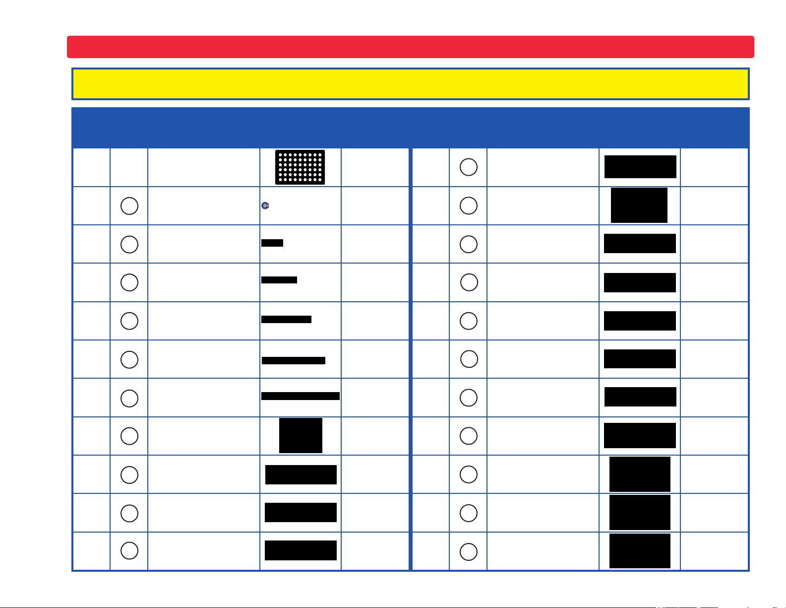
Parts List (Colors and styles may vary) Symbols and Numbers
Important: If any parts are missing or damaged in shipping, DO NOT RETURN TO Target. Call toll-free (800) 533-2441 or e-mail to
help@elenco.com. Customer Service ● 150 Carpenter Ave. ● Wheeling, IL 60090 U.S.A.
Qty. ID Name Symbol Part # Qty. ID Name Symbol Part #
r 1
r 3
r 6
r 3
r 1
r 1
r 1
r 1
1
2
3
4
5
6
B1
Base Grid
(11.0” x 7.7”)
1-Snap Wire 6SC01
2-Snap Wire 6SC02
3-Snap Wire 6SC03
4-Snap Wire 6SC04
5-Snap Wire 6SC05
6-Snap Wire 6SC06
Battery Holder Two 1.5V type AA (not incl.)
uses
6SCBG
6SCB1
r 1
r 1
r 1
r 1
r 1
r 1
r 1
r 1
r 1
M1
Q2
R1
R2
RP
S1
S2
SP
Motor
Glow Fan
NPN Transistor 6SCQ2
100W Resistor 6SCR1
1KW Resistor 6SCR2
Photoresistor 6SCRP
Slide Switch 6SCS1
Press Switch 6SCS2
Speaker 6SCSP
6SCM1
6SCM1FG
r 1
r 1
r 1
C5
D1
L1
470mF Capacitor 6SCC5
Red Light Emitting
Diode (LED)
2.5V Lamp 6SCL1
6SCD1
r 1
r 1
r 1
U1
U2
U3
Music
Integrated Circuit
Alarm
Integrated Circuit
Space War
Integrated Circuit
6SCU1
6SCU2
6SCU3
-2-
Page 4
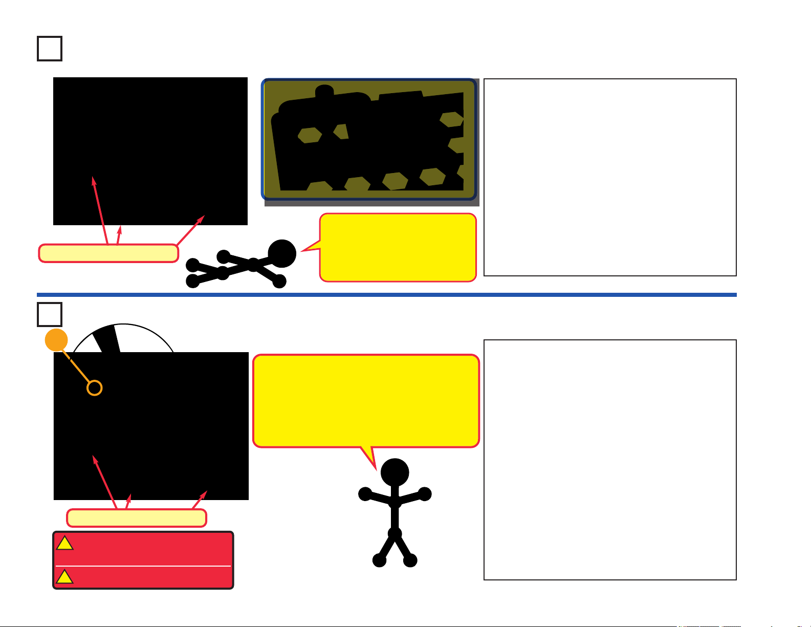
How to Use Circuit Maker Skill Builder 125
Circuit Maker Skill Builder 125 uses building
blocks with snaps to build the different
electronic circuits in the projects. Each block
has a function: there are switch blocks, light
blocks, battery blocks, different length wire
blocks, etc. These blocks are different colors
and have numbers on them so that you can
easily identify them. The blocks you will be
using are shown as color symbols with level
numbers next to them, allowing you to easily
snap them together to form a circuit.
For Example:
This is the switch block which is green and has
the marking on it. The part symbols in this
booklet may not exactly match the
appearance of the actual parts, but will clearly
identify them.
S2
You need a power source to build each circuit.
This is labeled and requires two (2) 1.5V
“AA” batteries (not included).
B1
Usually when the motor is used, the glow
fan will be placed on it. On top of the motor
shaft is a black plastic piece (the motor top)
with three little tabs. Lay the fan on the black
piece so the slots in its bottom “fall into place”
around the three tabs in the motor top. If not
placed properly, the fan will fall off when the
motor starts to spin.
M1
This is a wire block which is blue and comes
in different wire lengths.
3 4 5
This one has the number , , , ,
or on it depending on the length of the wire
6
connection required.
There is also a 1-snap wire that is used as a
spacer or for interconnection between
different layers.
2
-3-
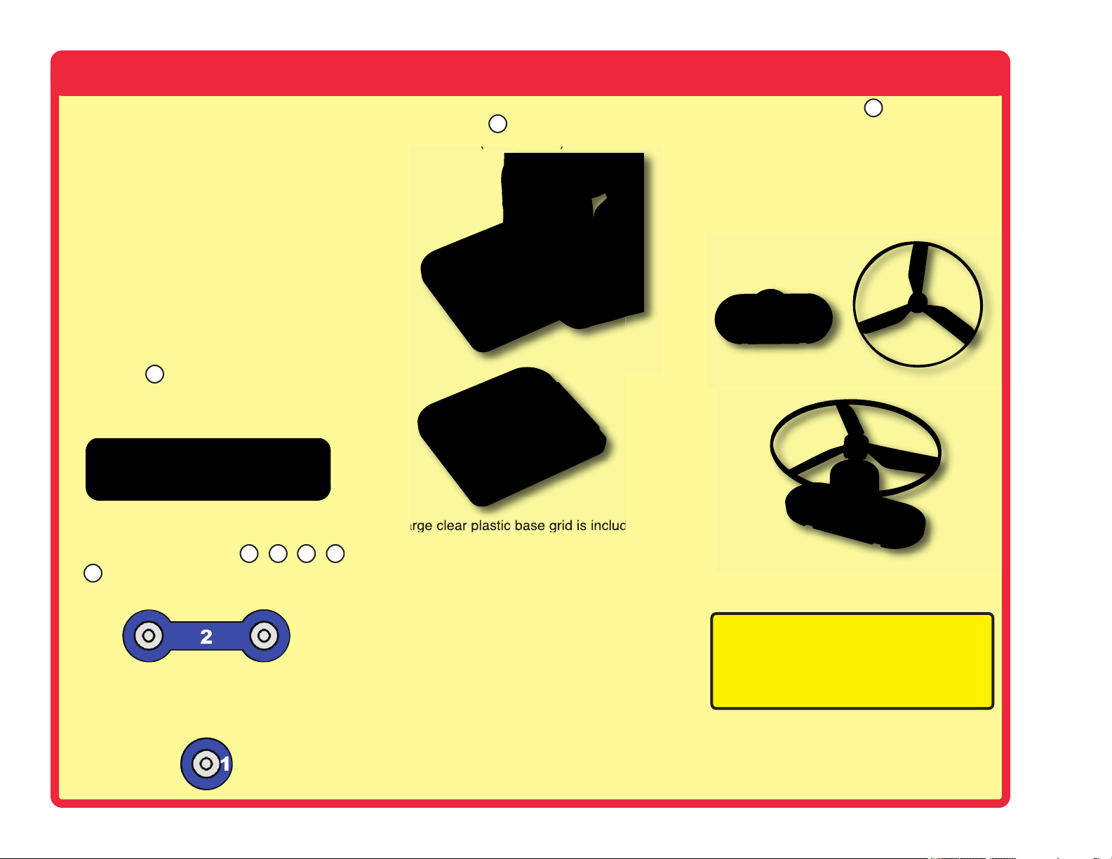
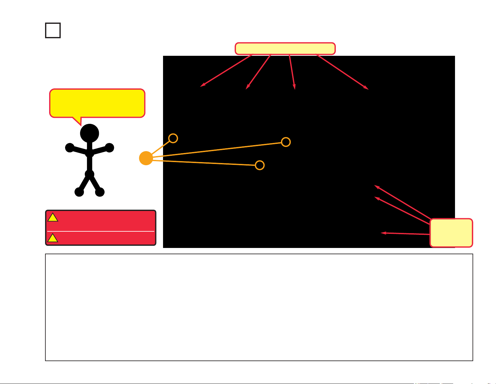
A large clear plastic base grid is included with
this kit to help keep the circuit blocks properly
spaced. You will see evenly spaced posts that
the different blocks snap into. The base has
rows labeled A-G and columns labeled 1-10.
Next to each part in every circuit drawing is a
small number in black. This tells you which
level the component is placed at. Place all
parts on level 1 first, then all of the parts on
level 2, then all of the parts on level 3, etc.
Note: While building the projects, be
careful not to accidentally make a direct
connection across the battery holder (a
“short circuit”), as this may damage and/or
quickly drain the batteries.
Page 5
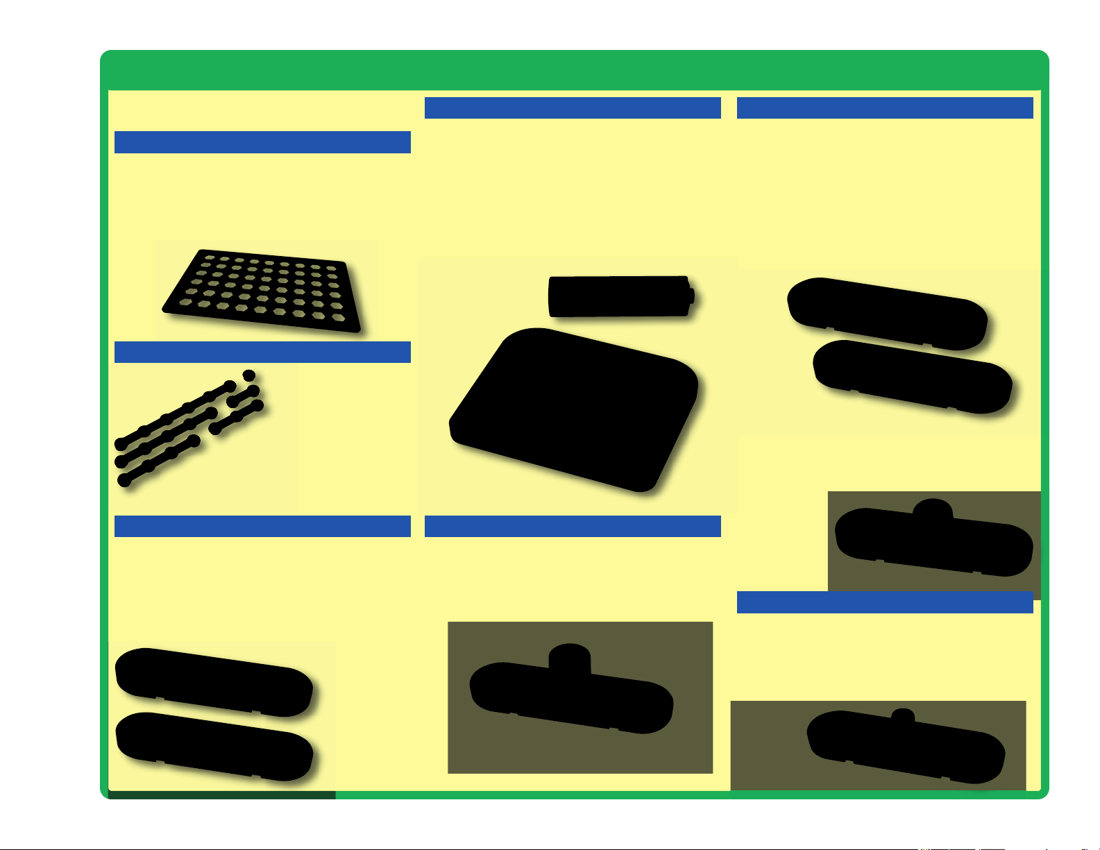
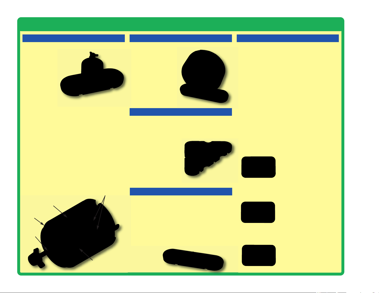
About Your Circuit Maker Skill Builder 125 Parts
(Part designs are subject to change without
notice).
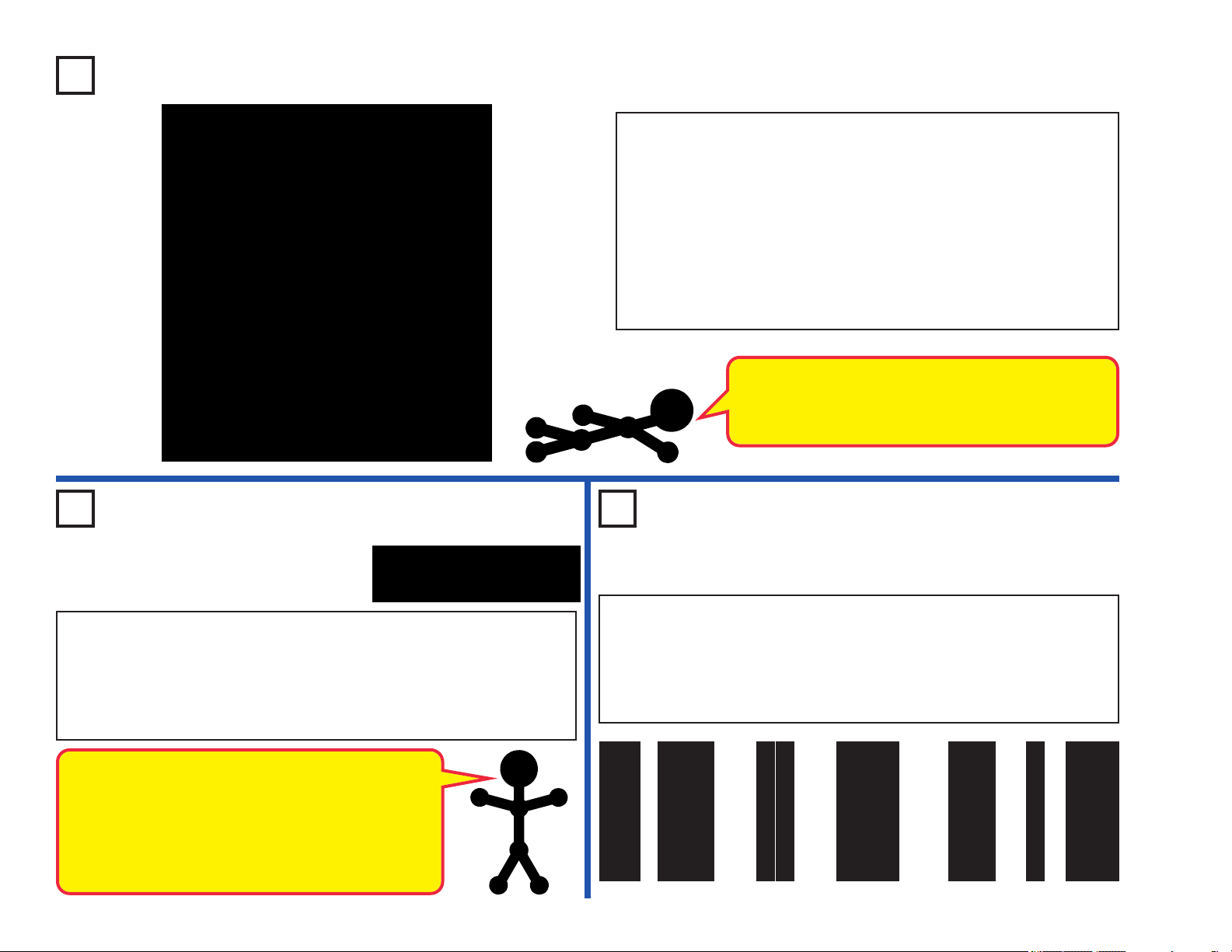
BASE GRID
The base grid is a platform for mounting parts
and wires. It functions like the printed circuit
boards used in most electronic products, or like
how the walls are used for mounting the
electrical wiring in your home.
SNAP WIRES
The blue snap wires
are wires used to
connect components.
They are used to transport
electricity and do not affect
circuit performance. They come in
different lengths to allow orderly
arrangement of connections on the base grid.
SLIDE & PRESS SWITCHES
The slide & press switches (S1 & S2) connect
(pressed or “ON”) or disconnect (not pressed or
“OFF”) the wires in a circuit. When ON they
have no effect on circuit performance. Switches
turn on electricity just like a faucet turns on
water from a pipe.
BATTERY HOLDER
The batteries (B1) produce an electrical voltage
using a chemical reaction. This “voltage” can be
thought of as electrical pressure, pushing
electricity through a circuit just like a pump
pushes water through pipes. This voltage is
much lower and much safer than that used in
your house wiring. Using more batteries
increases the “pressure”, therefore, more
electricity flows.
Battery Holder (B1)
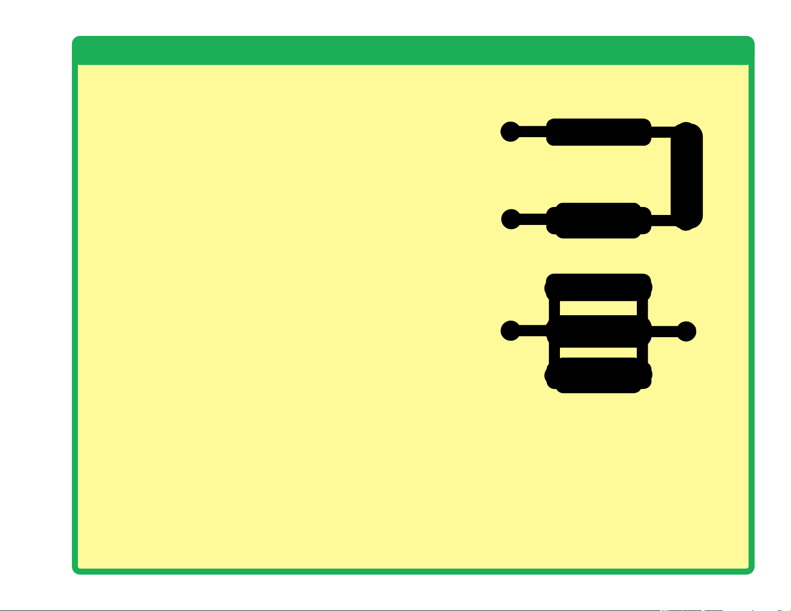
LAMP
A light bulb, such as in the 2.5V lamp (L1),
contains a special thin high-resistance wire.
When a lot of electricity flows through, this wire
gets so hot it glows bright. Voltages above the
bulb’s rating can burn out the wire.
RESISTORS
Resistors “resist” the flow of electricity and are
used to control or limit the current in a circuit.
Circuit Maker Skill Builder 125 includes 100W
(R1) and 1KW (R2) resistors (“K” symbolizes
1,000, so R2 is really 1,000W). Materials like
metal have very low resistance (<1W), while
materials like paper, plastic, and air have nearinfinite resistance. Increasing circuit resistance
reduces the flow of electricity.
Resistors (R1 & R2)
The photoresistor (RP) is a light-sensitive
resistor, its value changes from nearly infinite in
total darkness to about 1,000W when a bright
light shines on it.
Photoresistor (RP)
CAPACITOR
The 470mF capacitor (C5) can store electrical
pressure (voltage) for a period of time. This
storage ability allows it to block stable voltage
signals and pass changing ones. Capacitors are
used for filtering and delay circuits.
Slide & Press
Switches
(S1 & S2)
Lamp (L1)
Capacitor (C5)
-4-
Page 6
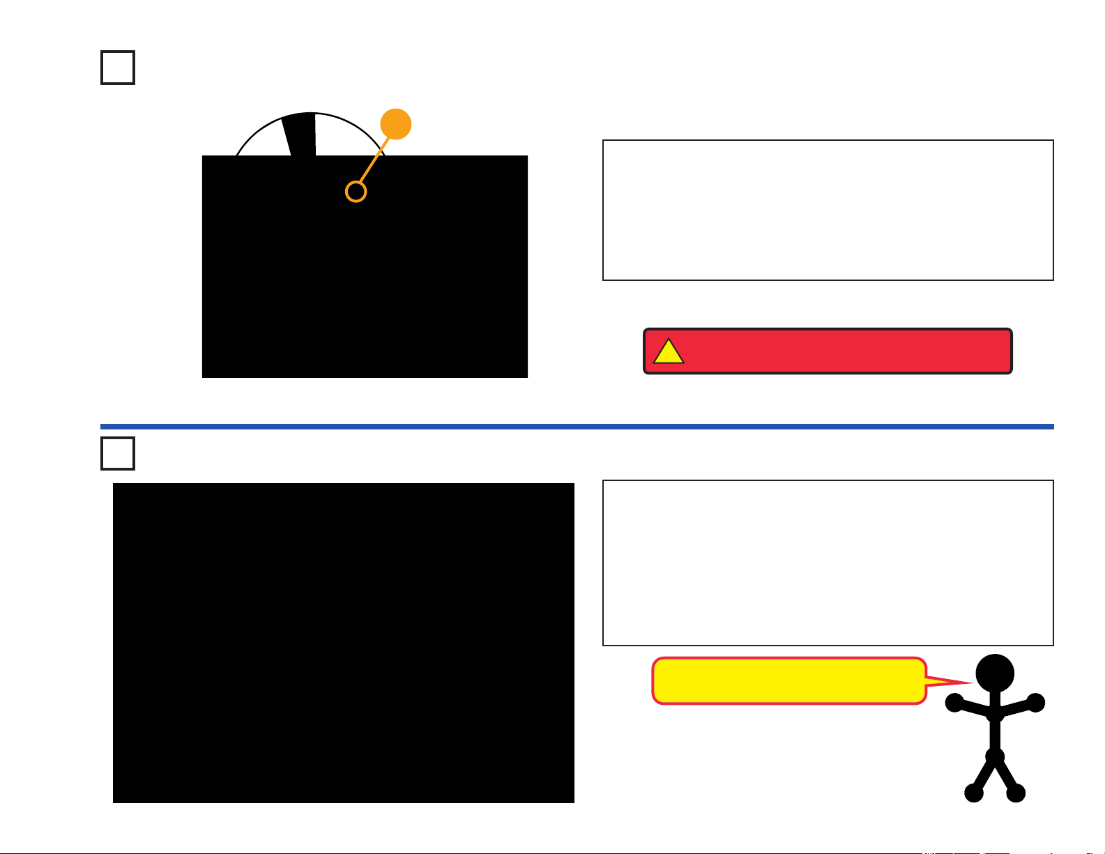
About Your Circuit Maker Skill Builder 125 Parts
MOTOR
The motor (M1) converts electricity into
mechanical motion. An electric
current in the motor will
turn the shaft and the
motor blades, and the fan
blade if it is on the
motor.
Motor (M1)
How does electricity turn the shaft in the motor?
The answer is magnetism. Electricity is closely
related to magnetism, and an electric current
flowing in a wire has a magnetic field similar to
that of a very, very tiny magnet. Inside the motor
is a coil of wire with many loops wrapped around
metal plates. This is called an electromagnet. If
a large electric current flows through the loops,
it will turn ordinary metal into a magnet. The
motor shell also has a magnet on it. When
electricity flows through the electromagnet, it
repels from the magnet on the motor shell and
the shaft spins. If the fan is on the motor shaft,
then its blades will create airflow.
Power Contacts
Magnet
Shell
Shaft
Electromagnet
SPEAKER
The speaker (SP) converts electricity into
sound by making mechanical vibrations. These
vibrations create variations in air pressure,
which travel across the
room. You “hear” sound
when your ears feel
these air pressure
variations.
Speaker (SP)
TRANSISTOR
The NPN transistor (Q2) is a component that
uses a small electric current to control a large
current, and is used in switching, amplifier, and
buffering applications. Transistors are easy to
miniaturize, and are the
main building blocks of
integrated circuits
including the microprocessor and memory
circuits in computers.
NPN Transistor (Q2)
LED
The red LED (D1) is a light emitting diode and
may be thought of as a special one-way light
bulb. In the “forward” direction, (indicated by the
“arrow” in the symbol) electricity flows if the
voltage exceeds a turn-on threshold (about
1.5V); brightness then increases. A high current
will burn out an LED, so the current must be
limited by other components in the circuit. LEDs
block electricity in the “reverse” direction.
LED (D1)
INTEGRATED CIRCUITS (ICs)
Some types of electronic components can be
super-miniaturized, allowing many thousands of
parts to fit into an area smaller than your
fingernail. These “integrated circuits” (ICs) are
used in everything from simple electronic toys to
the most advanced computers. The music,
alarm, and space war ICs (U1, U2, and U3) in
Circuit Maker Skill Builder 125 are actually
modules containing specialized soundgeneration ICs and other supporting components
(resistors, capacitors, and transistors) that are
always needed with them. This was done to
simplify the connections you need to make to use
them. The descriptions for these modules are
given here for those interested, see the projects
for connection examples:
Music IC:
Connections:
TRG
(+) HLD
Alarm IC:
IN1
IN2 IN3
(–)
Space War IC:
(+)
IN1
OUT(–)
OUT
OUT
IN2(–)
(+) - power from batteries
(–) - power return to batteries
OUT - output connection
HLD - hold control input
TRG - trigger control input
Music for a few seconds on powerup, then hold HLD to (+) power or
touch TRG to (+) power to resume
music.
Connections:
IN1, IN2, IN3 - control inputs
(–) - power return to batteries
OUT - output connection
Connect control inputs to (+) power
to make five alarm sounds, see
project 22 for configurations.
Connections:
(+) - power from batteries
(–) - power return to batteries
OUT - output connection
IN1, IN2 - control inputs
Connect each control input to (–)
power to sequence through 8
sounds.
-5-
Page 7
Introduction to Electricity
What is electricity? Nobody really knows. We only know how to produce it,
understand its properties, and how to control it. Electricity is the movement of
sub-atomic charged particles (called electrons) through a material due to
electrical pressure across the material, such as from a battery.
Power sources, such as batteries, push electricity through a circuit, like a pump
pushes water through pipes. Wires carry electricity, like pipes carry water.
Devices like LEDs, motors, and speakers use the energy in electricity to do
things. Switches and transistors control the flow of electricity like valves and
faucets control water. Resistors limit the flow of electricity.
The electrical pressure exerted by a battery or other power source is called
voltage and is measured in volts (V). Notice the “+” and “–” signs on the battery;
these indicate which direction the battery will “pump” the electricity.
The electric current is a measure of how fast electricity is flowing in a wire, just
as the water current describes how fast water is flowing in a pipe. It is expressed
in amperes (A) or milliamps (mA, 1/1,000 of an ampere).
The “power” of electricity is a measure of how fast energy is moving through a
wire. It is a combination of the voltage and current (Power = Voltage x Current).
It is expressed in watts (W).
The resistance of a component or circuit represents how much it resists the
electrical pressure (voltage) and limits the flow of electric current. The
relationship is Voltage = Current x Resistance. When the resistance increases,
less current flows. Resistance is measured in ohms (W), or kilo ohms (KW,
1,000 ohms).
There are two ways of arranging parts in a circuit, in series or
in parallel. Here are examples:
Series Circuit
Parallel Circuit
Nearly all of the electricity used in our world is produced at enormous generators
driven by steam or water pressure. Wires are used to efficiently transport this
energy to homes and businesses where it is used. Motors convert the electricity
back into mechanical form to drive machinery and appliances. The most
important aspect of electricity in our society is that it allows energy to be easily
transported over distances.
Note that “distances” includes not just large distances but also tiny distances. Try
to imagine a plumbing structure of the same complexity as the circuitry inside a
portable radio - it would have to be large because we can’t make water pipes so
small. Electricity allows complex designs to be made very small.
Placing components in series increases the resistance;
highest value dominates. Placing components in parallel
decreases the resistance; lowest value dominates.
The parts within these series and parallel sub-circuits may be
arranged in different ways without changing what the circuit
does. Large circuits are made of combinations of smaller
series and parallel circuits.
-6-
Page 8
DOs and DON’Ts of Building Circuits
After building the circuits given in this booklet, you may wish to experiment on
your own. Use the projects in this booklet as a guide, as many important design
concepts are introduced throughout them. Every circuit will include a power
source (the batteries), a resistance (which might be a resistor, capacitor,
speaker, integrated circuit, etc.), and wiring paths between them and back. You
must be careful not to create “short circuits” (very low-resistance paths across
the batteries, see examples at right) as this will damage components
quickly drain your batteries. Only connect the ICs using configurations given in
the projects, incorrectly doing so may damage them. ELENCO®is not
responsible for parts damaged due to incorrect wiring.
Here are some important guidelines:
ALWAYS USE EYE PROTECTION WHEN ExPERIMENTING ON YOUR
OWN.
ALWAYS include at least one component that will limit the current through a
circuit, such as the speaker, lamp, ICs (which must be connected
properly), motor, photoresistor, or resistor.
ALWAYS use the LED, NPN transistor, and switches in conjunction with other
components that will limit the current through them. Failure to do so
will create a short circuit and/or damage those parts.
ALWAYS disconnect your batteries immediately and check your wiring if
something appears to be getting hot.
ALWAYS check your wiring before turning on a circuit.
ALWAYS connect capacitors so that the “+” side gets the higher voltage.
ALWAYS connect ICs using configurations given in the projects or as per the
connection descriptions for the parts.
NEVER connect to an electrical outlet in your home in any way.
NEVER leave a circuit unattended when it is turned on.
NEVER touch the motor when it is spinning at high speed.
For all of the projects given in this book, the parts may be arranged in different
ways without changing the circuit. For example, the order of parts connected in
series or in parallel does not matter — what matters is how combinations of
these sub-circuits are arranged together.
and/or
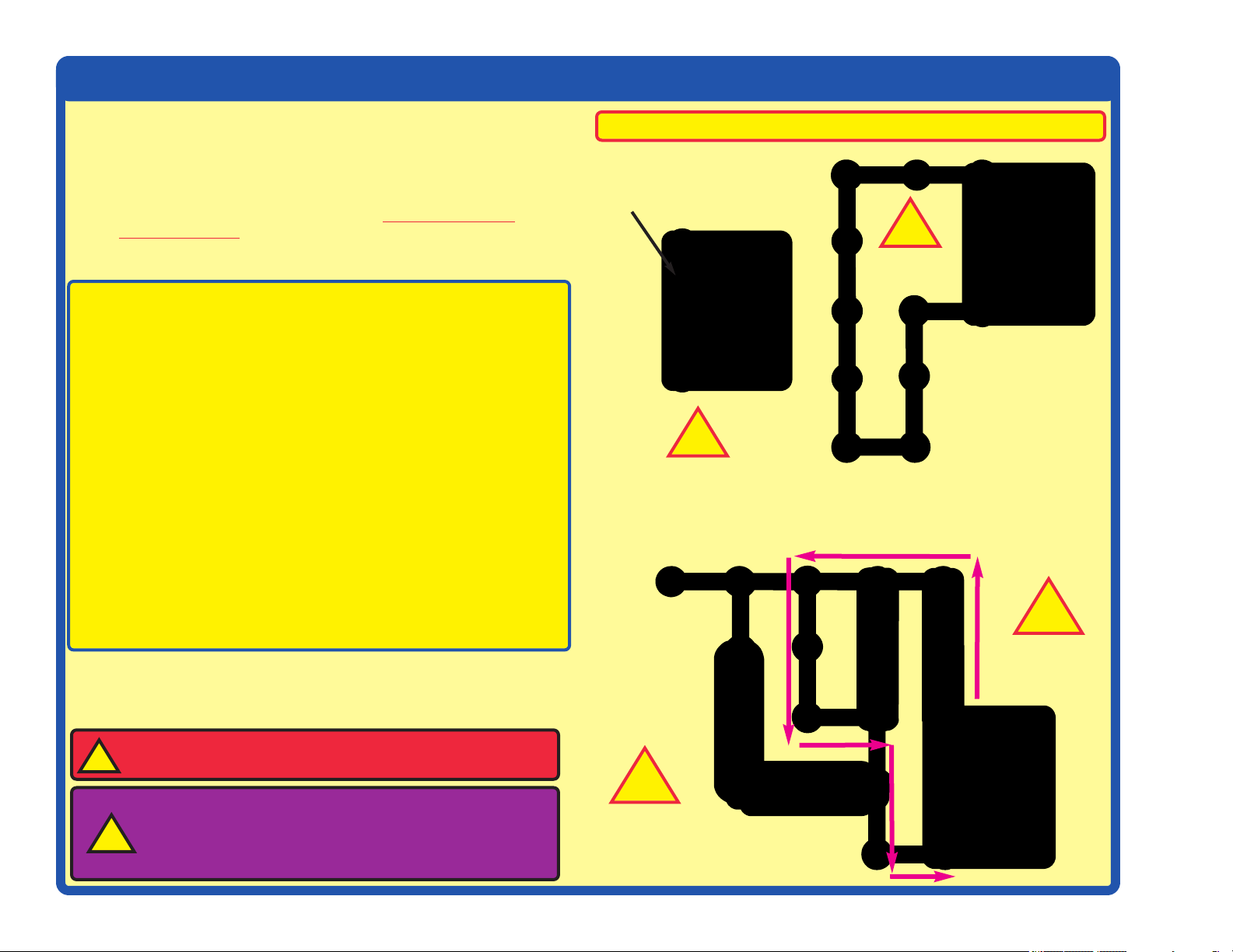
Examples of SHORT CIRCUITS - NEVER DO THESE!!!
Placing a 3-snap wire directly
across the batteries is a
SHORT CIRCUIT.
!
NEVER
DO!
This is also a
SHORT CIRCUIT.
NEVER
!
When the slide switch (S1) is turned on, this large circuit has a SHORT
CIRCUIT path (as shown by the arrows). The short circuit prevents any
other portions of the circuit from ever working.
DO!
!
NEVER
DO!
-7-
WARNING: SHOCK HAZARD -
Skill Builder 125 to the electrical outlets in your home in any way!
!
Warning to Circuit Maker owners: Do not connect
additional voltage sources from other sets, or you
!
may damage your parts. Contact ELENCO®if you
have questions or need guidance.
Never connect Circuit Maker
!
NEVER
DO!
Page 9
Advanced Troubleshooting
(Adult supervision recommended)
ELENCO®is not responsible for parts
damaged due to incorrect wiring.
If you suspect you have damaged parts,
you can follow this procedure to
systematically determine which ones need
replacing:
1.
2.5V lamp (L1), motor (M1), speaker
(SP), and battery holder (B1): Place
batteries in holder. Place the 2.5V lamp
directly across the battery holder, it
should light. Do the same with the
motor (motor + to battery +), it should
spin to the right at high speed. “Tap” the
speaker across the battery holder
contacts, you should hear static as it
touches. If none work then replace your
batteries and repeat, if still bad then the
battery holder is damaged. If the motor
spins but does not balance the fan,
check the black plastic piece on the
motor shaft; it should have 3 prongs.
3. Slide switch (S1) and Press switch
(S2): Build Project #1, if the lamp (L1)
doesn’t light then the slide switch is
bad. Replace the slide switch with the
press switch to test it.
4. 100W resistor (R1), 1KW resistor
(R2), and LED (D1): Build Project #11
except initially use the speaker (SP) in
place of the resistor, the LED should
light. Then, replace the speaker with
the 100W resistor; the LED should still
light. Then, replace the 100W resistor
with the 1KW resistor; the LED should
light but not as brightly.
5. Alarm IC (U2): Build Project #21, you
should hear a siren. Then place a 3snap wire between grid locations A1
and C1, the sound is different. Then
move the 3-snap from A1-C1 to A3-C3
to hear a third sound.
7. Space war IC (U3) and photoresistor
(RP): Build Project #4, both switches
(S1 and S2) should change the sound.
Then replace the slide switch (S1) with
the photoresistor, waving your hand
over it should change the sound.
8. NPN transistor (Q2): Build Project
#31. When both switches are on, the
lamp lights and motor spins. If one
switch is off, nothing happens.
9. 470mF capacitor (C5): Build Project
#50, then press and release the switch.
The LED should go off slowly.
Customer Service
Call toll-free: (800) 533-2441
e-mail: help@elenco.com
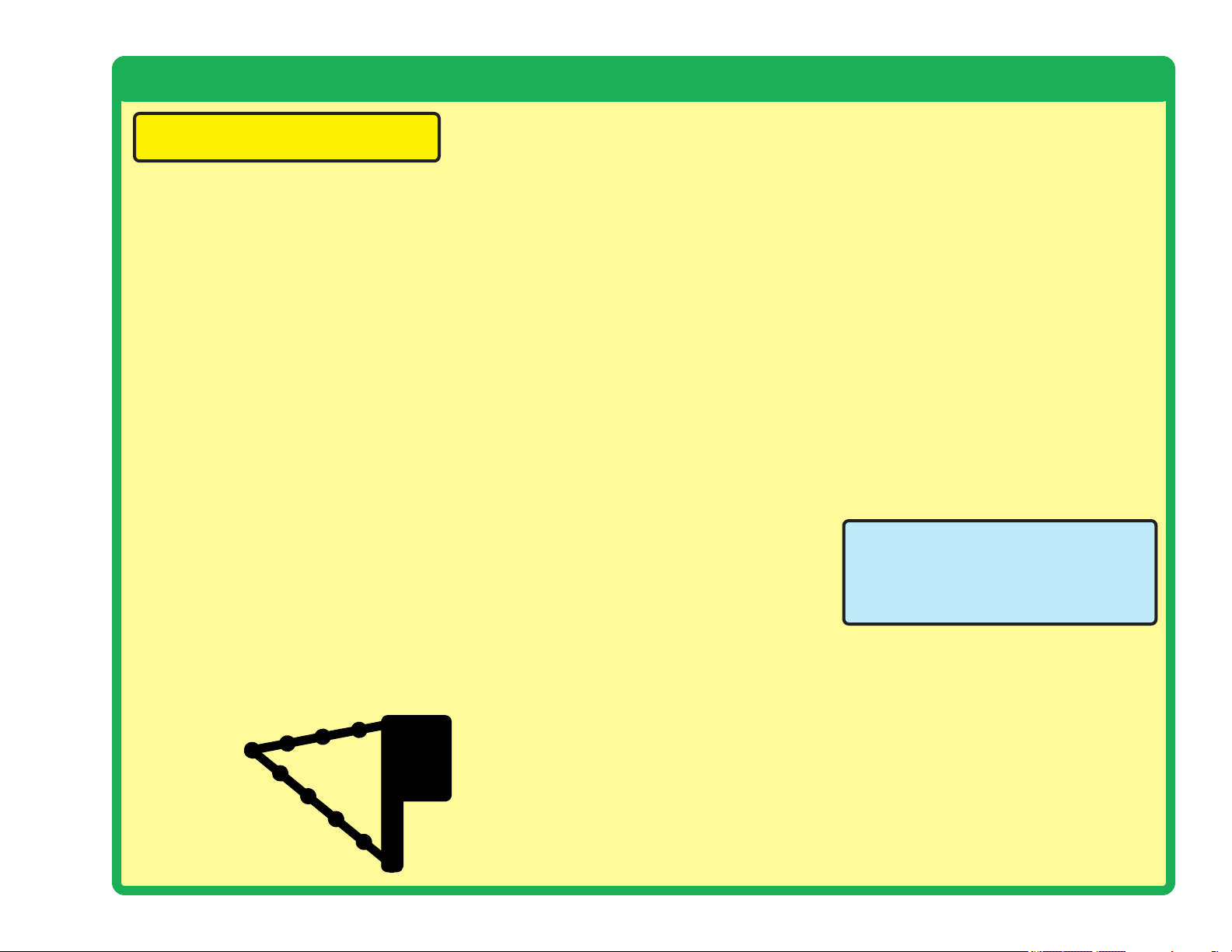
2. Snap wires: Use this mini-circuit to test
the 5-snap and 6-snap wires. The lamp
should light. Then test each of the 1snap, 2-snap, 3-snap, and 4-snap
wires by connecting them
b e t w e e n
the ends of
the 5-snap
and 6-snap.
6. Music IC (U1): Build Project #86 but
use the press switch (S2) in place of
the photoresistor (RP). Turn it on and
the LED (D1) flickers for a while and
stops, it resumes if you press and hold
down the press switch. Then touch a 3snap wire across base grid points A1
and C1 and the flickering resumes for a
while.
-8-
Page 10

Project Listings
Project # Description Page #
1 Turn on the Light
2 Up, Up, and Away! 11
3 Super Circuit 12
4 Space War 13
5 Loud in Light 13
6 Paper Player 13
7 Stick Around Saucer 14
8 Rotate & Roar 14
9 Spin & Dim 15
10 Balanced Buddies 15
11 The Diode Dude 16
12 One Way Works 16
11
Project # Description
22 Laser Blaster 21
23 Mind Reader Game 22
24 Don’t Make a Sound 23
25 Discover the Diode 23
26 Shine On Siren 24
27 Shooting Sounds 24
28 Song & Siren 24
29 Ambulance Melody 24
30 Static Song 24
31 Transistor Control 25
32 Slow & Bright 25
33 Stop & Shine 25
Page #
Project # Description Page #
43 Motor Magic 28
44 Spin & Shoot 28
45 Spin Out Siren 28
46 Whirl Out Warning 28
47 Turn a Tune 28
48 Wave & Watch 29
49 Switching Sounds 29
50 Lingering Light 30
51 Current Splitter 30
52 Light Up & Listen 30
53 Auto-Off Night Light 31
54 Auto-Off Day Light 31
13 Clippy the Conductor 17
14 Nifty Noises 17
15 Mumbling Motor 18
16 Lift Loss 18
17 Hi-Low Fan 19
18 Fuse or Lose 19
19 Magical Music 20
20 Press & Play 20
21 Simple Siren 21
-9-
34 Murky Motor 25
35 Mixed Up Music 26
36 Blaster Disaster 26
37 Siren & Song 26
38 Ambulance Song 26
39 Space Battle 27
40 Bizarre Blinker 27
41 Sporadic Sounds 27
42
Blinking Double Flashlight
27
55 Reflection Detector 32
56 Music Reflection Detector 32
57 Laser Flasher 33
58 Flash & Flicker 33
59 Spinning Rings 34
60 Strobe the House Lights 34
61 Race Game 35
62
63 Spin Draw 36
Using Parts as Conductors
35
Page 11

Project Listings
Project # Description Page #
64 Singing Motor 36
65 Visual Volume 37
66 Daylight Alarm 37
67 Bang-Bang Bright 37
68 Daylight Danger 37
69 Crooks & Cars 37
70 Pop On, Pop Off 38
71 Little R Rules 38
72 Big R Rules 38
73 Little to Big 39
74 Luminate & Rotate 39
75 Light to Light 39
Project # Description
85 Electron Warehouse 44
86 Light Makes Light 45
87 Go & Glow 45
88 Spin & Stop 45
89 Flashing Flare 46
90 Touch & Go 46
91 Two-Tone Twinkler 46
92 Fan Flash Energy 47
93 Photo Timer Light 47
94 Room Light to Red Light 47
95 Fun with the Alarm IC 48
96 Dancing Motor 48
Page #
Project # Description
106 Lagging Light 52
Sonic Flasher 53
107
108 Stay or Blink 53
109 Glow & Go 54
110 Fading Siren 54
111 Light the Motor 55
112 Motor Space Sounds 55
113 Twist & Blink 55
114 Morse Code 56
115 Light to Dark 56
116 Power Shifter 56
117 Touch of Light 57
Page #
76 Switch & Store 40
77 Crazy Combo 40
78 Alien Alarm 41
79 Same or “NOT” 41
80 This OR That 42
81 This AND That 42
82 Neither This NOR That 43
83 NOT This AND That 43
84 Two-way Light Switch 44
97 Musical Light 48
98 Music Alarm Combo 49
99 Hit the Target 49
100 Many Missiles 49
101 Sing & Fling 50
102 Power Pitch 50
103 Long Gone Light 51
104 Slow Siren Changer 51
105 The Dark Dimmer 52
118 Change & Charge 57
119 Electricity You Can Wear 58
120 Electricity In Your Hair 58
121 Bending Water 59
122 Static Tricks 59
123 Sunrise Light 60
124 Light-controlled Lamp 60
125 Motor-controlled Lamp 60
-10-
Page 12
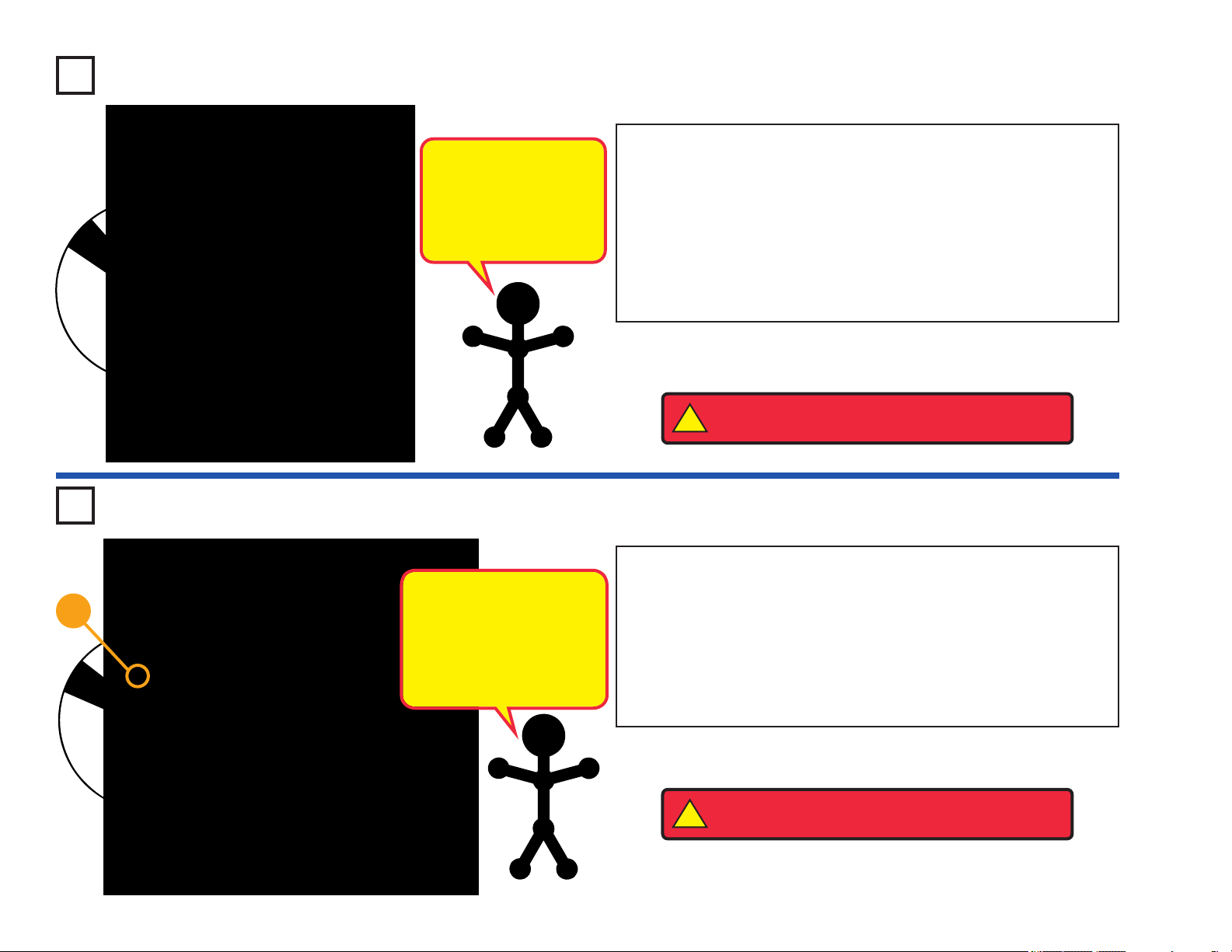
Project #1
Turn on the Light
Circuit Maker Skill Builder 125 uses electronic blocks
that snap onto a clear plastic grid to build different
circuits. These blocks have different colors and
numbers on them so that you can easily identify them.
Build the circuit shown on the left by placing all the
parts with a black 1 next to them on the board first.
Then, assemble parts marked with a 2. Install two (2)
“AA” batteries (not included) into the battery holder
(B1) if you have not done so already.
Placement Level Numbers
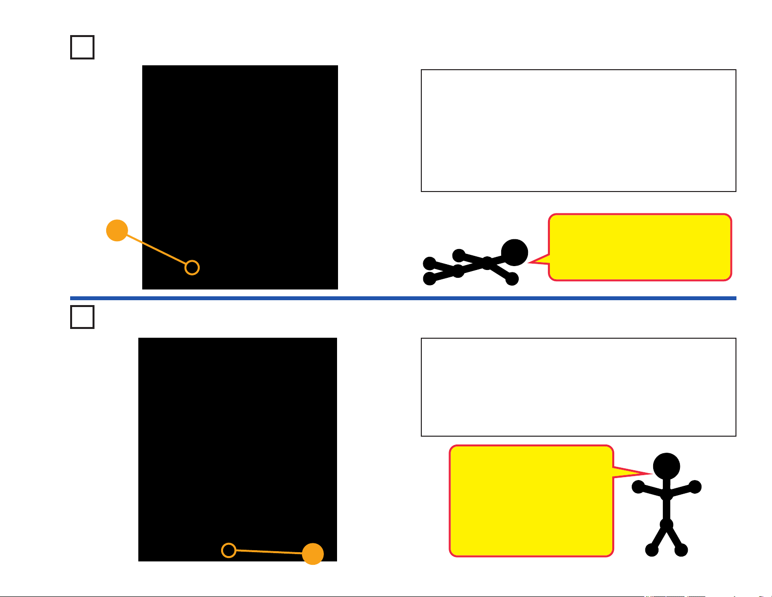
Project #2
+
Snappy says the lamp contains
a special thin high-resistance
wire. When a lot of electricity
flows through it, it gets so hot it
glows bright.
Up, Up, and Away!
The air is being blown down through the blade
and the motor rotation locks the fan on the shaft.
When the motor is turned off, the blade unlocks
from the shaft and is free to act as a propeller
and fly through the air. If speed of rotation is too
slow, the fan will remain on the motor shaft
because it does not have enough lift to propel it.
When you turn on the slide switch (S1), electricity
flows from the batteries through the lamp (L1) and
back to the batteries through the switch. The switch
completes the circuit. The lamp gets bright as
electricity flows through it.
Build the circuit shown on the left by placing the parts
with a black 1 next to them on the base grid first.
Then, assemble parts marked with a 2. Place the
glow fan on the motor. New alkaline batteries are
recommended for this project.
Turn on the slide switch (S1), wait for the motor to
reach full speed, then turn off the switch. The glow
fan should rise and float through the air like a flying
saucer. Be careful not to look directly down on the
glow fan when it is spinning.
If the fan doesn’t fly off, then turn the switch on and
off several times rapidly when it is at full speed.
-11-
Placement Level Numbers
WARNING: Moving parts. Do not touch the
!
fan or motor during operation. Do not lean
over the motor.
WARNING: Fan may not rise until switch is
!
released.
The glow fan will glow in the dark. It will glow best
after absorbing sunlight for a while. The glow fan is
made of plastic, so be careful not to let it get hot
enough to melt. The glow looks best in a dimly lit
room.
Page 13
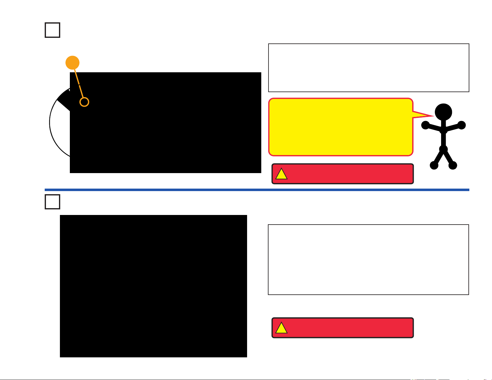
Project #3 Super Circuit
This complex circuit is pictured
on the box cover. Use that as a
guide to help in building it.
WARNING: Moving parts. Do not touch the
!
fan or motor during operation. Do not lean
over the motor.
WARNING: Fan may not rise until switch is
!
released.
Placement Level Numbers
+
Placement
Level
Numbers
Circuit Maker Skill Builder 125 uses electronic
blocks that snap onto a clear plastic grid to
build different circuits. These blocks have
different colors and numbers on them so that
you can easily identify them.
Build the circuit shown above by placing all the
parts with a black 1 next to them on the board
first. Then, assemble parts marked with a 2.
Then, assemble parts marked with a 3. Then,
assemble the part marked with a 4 (the alarm
IC (U2), which should be placed directly over
the music IC (U1)). Install two (2) “AA” batteries
(not included) into the battery holder (B1).
Place the glow fan on the motor (M1).
Turn on the slide switch (S1). You hear music
and alarm sounds, and the red LED (D1) lights.
The lamp (L1) may light briefly before the red
LED turns on. Cover the photoresistor (RP) to
change the sound a little.
Push the press switch (S2) to spin the motor
and glow fan. Release the press switch when
the motor is spinning at full speed. The glow fan
should float through the air like a flying saucer.
Be careful not to look directly down on the glow
fan when it is spinning.
If the fan doesn’t fly off, then push and release
the press switch several times rapidly when it is
at full speed.
If the 470mF capacitor (C5) is discharged when
you turn on the slide switch, then the lamp will
light for a few seconds as the circuit charges up
C5. L1 will not light again until C5 is
discharged. To discharge C5, remove it from
the circuit and place it directly on the 4-snap
wire for an instant, then move it back to its
normal spot in the circuit.
-12-
Page 14
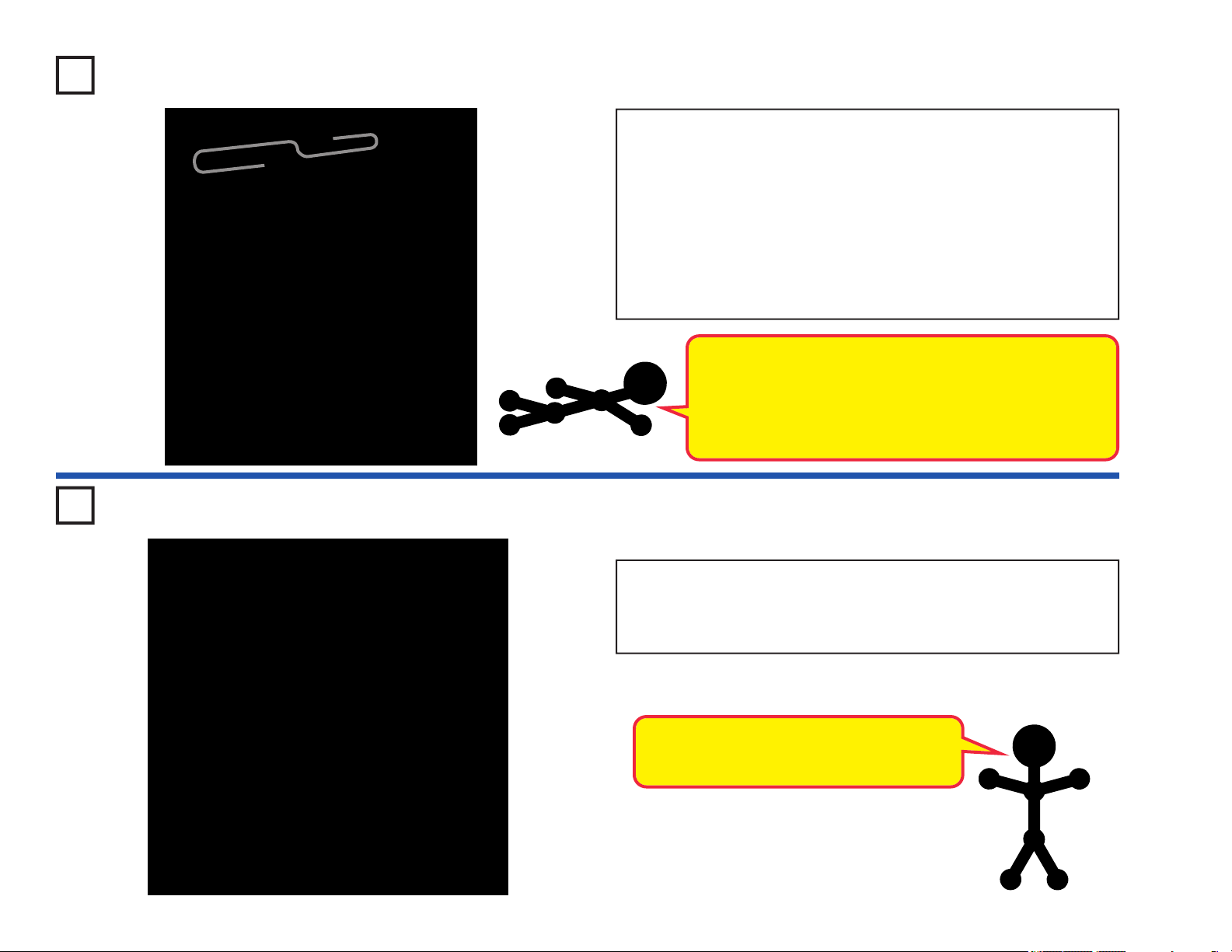
Project #4 Space War
Build the circuit shown on the left, which uses the space war integrated
circuit. Activate it by flipping the slide switch (S1) or pressing the press
switch (S2), do both several times and in combination. You will hear an
exciting range of sounds, as if a space war is raging!
The space war IC (U3) is a super-miniaturized electronic circuit that
can play a variety of cool sounds stored in it by using just a few extra
components.
In movie studios, technicians are paid to insert these sounds at the
precise instant a gun is fired. Try making your sound occur at the same
time an object hits the floor. It is not as easy as it sounds.
The Space War, Alarm, and Music ICs contain
specialized ICs combined with other electrical
components (resistors, capacitors, transistors)
designed to produce various cool sounds and music.
Project #5
Loud in Light
Use the circuit from Project #4 above, but replace the slide switch (S1)
with the photoresistor (RP). The circuit immediately makes noise. Try
turning it off. If you experiment, then you can see that the only ways to
turn it off are to cover the photoresistor, or to turn off the lights in the room
(if the room is dark). Since light is used to turn on the circuit, you might
say it is a “light switch”.
The photoresistor contains material that changes its
resistance when it is exposed to light; as it gets more
light, the resistance of the photoresistor decreases.
Parts like this are used in a number of ways that affect
our lives. For example, you may have streetlights in
your neighborhood that turn on when it starts getting
dark and turn off in the morning.
-13-
Project #6
Paper Player
Use the same circuit as for Project #5. Find a piece of white paper that
has a lot of large black or dark areas on it, and slowly slide it over the
photosensitive resistor. You may need to shine a flashlight over the paper.
You should hear the sound pattern constantly changing, as the white and
dark areas of the paper control the light to the photosensitive resistance.
You can also try the pattern below or something similar to it.
Page 15
Project #7
Stick Around Saucer
+
Build the circuit shown on the left which is the same as the circuit in
Project #2 but with the motor part reversed. Place the glow fan on the
motor.
Turn on the slide switch (S1), wait for the motor to reach full speed,
then turn off the switch. This time, the glow fan does not fly because
the fan is now rotating in the opposite direction such that the airflow is
pushing the fan downward.
WARNING: Moving parts. Do not touch the fan or
!
motor during operation.
Project #8 Rotate & Roar
Build the circuit shown on the left, but leave the fan off the motor (M1).
When you turn on the slide switch (S1), the music may play for a short
time and then stop. After the music has stopped, spin the motor with
your fingers. The music should play again for a short time, then stop.
Now replace the 100W resistor (R1) with a 3-snap wire, and notice how
the sound is affected.
In this project, you changed the amount of current that goes through
the speaker (SP) and increased the sound output of the speaker.
Resistors are used throughout electronics
to limit the amount of current that flows.
-14-
Page 16
Project #9 Spin & Dim
+
The parts are arranged
as a series circuit. You
can swap the locations
of any of the parts
without affecting circuit
operation.
Build the circuit shown on the left.
When you turn on the slide switch (S1), the fan will spin and the lamp
(L1) should turn on. The fan will take a while to start turning due to
inertia. Inertia is the property that tries to keep a body at rest from
moving and tries to keep a moving object from stopping.
The lamp helps protect the motor from getting the full voltage when the
switch is turned on. Part of the voltage goes across the lamp and the
rest goes across the motor. Remove the fan and notice how the lamp
gets dimmer when the motor does not have to spin the fan blade.
WARNING: Moving parts. Do not touch the fan or
!
motor during operation.
Project #10 Balanced Buddies
Build the circuit shown on the left.
The parts are arranged as a
parallel circuit. Parallel
circuits are often used in
residential homes so that
turning on one device
doesn’t limit the current to
other devices.
When you turn on the slide switch (S1), both the fan and the lamp (L1)
should turn on. The fan will take a while to start turning due to inertia.
In this connection, the lamp does not change the current to the motor
(M1). The motor should start a little faster than in Project #9.
Remove the fan and notice how the lamp does not change in
brightness as the motor picks up speed. It has its own path to the
battery (B1).
-15-
WARNING: Moving parts. Do not touch the fan or
!
motor during operation.
Page 17
+
Project #11 The Diode Dude
Build the circuit shown on the left.
When you turn on the slide switch (S1), current flows from the batteries
(B1) through the switch, through the 100W resistor (R1), through the
LED (D1, light emitting diode) and back to the battery. The turned on
switch completes the circuit. The resistor limits the current and prevents
damage to the LED. NEVER PLACE AN LED DIRECTLY ACROSS
THE BATTERY! If no resistor is in the circuit, the battery may push
enough current through the LED to damage the semiconductor that is
used to produce the light.
LEDs are used in all types of electronic
equipment to indicate conditions and
pass information to the user of that
equipment. Can you think of something
you use everyday that has an LED in it?
Project #12 One Way Works
+
Rebuild the circuit used in Project #11 but put the LED in as shown on
the left.
This time when you turn on the slide switch (S1), current does not flow
from the batteries (B1) through the 100W resistor (R1) or through the
LED (D1), and hence the LED does not light up. This is because the
LED is in backwards. The LED is like a check valve that lets current
flow in only one direction (into the + end and out the other end).
An electronic component that
needs to be connected in one
direction is said to have polarity.
Other parts like this will be
discussed in future projects.
Placing the LED in backwards does
not harm it because the voltage is
not large enough to break down this
electronic component.
-16-
Page 18
Project #13 Clippy the Conductor
Rebuild the circuit from Project #11 but leave the slide switch (S1) out
as shown on the left.
When you place a paper clip across the terminals as shown in the
picture on the left, current flows from the batteries (B1) through the
100W resistor (R1), through the LED (D1), and back to the battery. The
paper clip completes the circuit and current flows through the LED.
Place your fingers across the terminals and the LED does not light.
Your body is too high of a resistance to allow enough current to flow to
light the LED. If the voltage, which is electrical pressure, was higher,
current could be pushed through your fingers and the LED would light.
This detector can be used to see if a material like plastic is a
good conductor or a poor conductor. Materials that make the
LED bright pass electricity easily, and are called conductors.
Most metals are good conductors, and copper is used in
most house wiring. Materials that block the flow of electricity
are called insulators. Plastic, paper and air are insulators.
Project #14 Nifty Noises
-17-
Build the circuit shown. Turn it on, press the press switch (S2) several
times, and wave your hand over the photoresistor (RP) to hear all the
sound combinations. You can make the sound from the alarm IC (U2)
louder by replacing the 100W resistor (R1) with the 2.5V lamp (L1).
A photoresistor is a light-controlled variable
resistor. The resistance of the photoresistor
decreases with increasing light intensity.
Page 19
+
Project #15
Place the fan on the motor (M1). Press the press switch (S2) and listen
to the motor. Why does the motor make sound?
If you replace the motor with the 2.5V lamp (L1), then it will work the
same as the “Hear the Motor” project, but only make noise when the
lamp is turned ON or OFF.
A motor uses magnetism to convert electrical
energy into mechanical spinning motion. As the
motor shaft spins around it connects / disconnects
several sets of electrical contacts to give the best
magnetic properties. As these contacts are
switched, an electrical disturbance is created,
which the speaker (SP) converts into sound.
Mumbling Motor
WARNING: Moving parts. Do not touch the
!
fan or motor during operation.
Project #16 Lift Loss
Build the circuit to the left.
Cover the photoresistor (RP) and turn on the slide switch (S1). The
motor (M1) should spin. If not, give it a push to get it started. Now
uncover the photoresistor or get a flashlight and shine it on the
photoresistor. The motor will slow down as more light reaches the
photoresistor, and will stop spinning if enough light reaches the
photoresistor. This circuit demonstrates how darkness can be used to
control a fan. Try this circuit with and without the fan on the motor.
WARNING: Moving parts. Do not touch the
!
fan or motor during operation.
-18-
Page 20
Project #17 Hi-Low Fan
Build the circuit shown on the left.
WARNING:
!
Moving parts. Do not
touch the fan or motor
during operation.
When you close the slide switch (S1), current flows from the batteries
through the slide switch (S1), motor (M1), the lamp (L1), and back to
the battery (B1). When the press switch (S2) is closed, the lamp is
shorted and motor speed increases.
The principle of removing resistance to
increase motor speeds is only one way of
changing the speed of the motor. Commercial
fans do not use this method because it would
produce heat in the resistor and fans are used
to cool circuits by moving air over them.
Commercial fans change the amount of
voltage that is applied to the motor using a
transformer or other electronic device.
-19-
Project #18
WARNING:
!
Moving parts. Do not
touch the fan or motor
during operation.
Many electronic products in
your home have a fuse that will
open when too much current is
drawn. Can you name some?
Fuse or Lose
Use the circuit built in Project #17.
When you close the slide switch (S1), current flows from the batteries
through the slide switch (S1), the lamp (L1), motor (M1), and back to the
battery (B1). Pretend the 2-snap wire marked fuse in the drawing on the
left is a device that will open the circuit if too much current is taken from
the battery. When press switch (S2) is closed, the light is shorted and
motor speed increases due to an increase in current to the motor. While
still holding press switch (S2) down, remove the 2-snap wire marked
fuse and notice how everything stops. Until the fuse is replaced, the
open circuit path protects the electronic parts. If fuses did not exist,
many parts could get hot and even start fires. Replace the 2-snap wire
and the circuit should return to normal.
Page 21

Project #19 Magical Music
Build the circuit shown on the left. When you turn on the slide switch
(S1), the music integrated circuit (U1) may start playing one song then
stop. Each time you press the press switch “doorbell button” (S2) the
song will play again and stop. Even if you let go of the press switch
(S2), the integrated circuit keeps the song playing until it has reached
the end of the song.
Musical integrated circuits are used to
entertain young children in many of the toys
and chairs made to hold infants. If the music
is replaced with words, the child can also
learn while they are entertained. Because of
great advances in miniaturization, many
songs are stored in a circuit no bigger than a
pinhead.
Project #20 Press & Play
Modify the circuit used in Project #19 to look like the one shown on the
left.
When you turn on the slide switch (S1), the music integrated circuit
(U1) may start playing one song then stop. The song will be much
louder than in the previous project because it is now being used as an
alarm. Each time you press the press switch “alarm button” (S2) after
the song stops playing, the song will play again, but only while you hold
the button down.
Having no resistor in series with the speaker
allows more current to flow through the speaker
producing a louder sound.
-20-
Page 22

Project #21 Simple Siren
Build the circuit shown on the left.
When you
should start sounding a very loud alarm sound. This integrated circuit is
designed to sweep through all the frequencies so even hard of hearing
people can be warned by the alarm.
turn on
If the alarm sound in this circuit
was passed through an amplifier
and installed into a police car, it
would also serve as a good
police siren.
the slide switch (S1), the integrated circuit (U2)
Project #22 Laser Blaster
-21-
Build the circuit shown on the left.
When you turn on the slide switch (S1), the integrated circuit (U2)
should start sounding a laser gun sound. This integrated circuit is
designed to produce different sounds that can easily be changed. You
can even switch the sound on and off quickly to add sound effects to
your games or recordings.
This circuit demonstrates
how sounds can be made
for electronic games.
Page 23

Project #23 Mind Reader Game
Build the circuit below. It uses a paper clip and
a 3-Snap Wire as “shorting bars”.
Setup: Player 1 sets the target by placing the
3-snap shorting bar under the paper on column
2, 3 or 4. Player 2 must NOT know where the
shorting bar is located under the paper.
The object is for Player 2 to guess the location
by placing one end of the paper clip on the 5snap wire as shown, and the other end of the
paper clip at positions X, Y, or Z and then
pressing the press switch (S2). If Player 2
places the paper clip at the correct position, the
sounds played indicates a “hit”. He keeps
guessing until he hits. After each hit, remove the
3-snap shorting bar and slide the switch off and
on to reset the sound.
Player 2 then sets the 2, 3, 4 side and player 1
tries his luck.
Play multiple rounds and see who gets the best
overall score. The winner will be the player who
is best at reading his opponent’s mind.
Paper Sheet to
hide position of
shorting bar
-22-
Page 24

Project #24 Don’t Make a Sound
Use the circuit from Project #23, but now place a 3-snap wire and the
LED (D1) as “shorting bars” under the paper sheet as shown on left.
Setup: Player 1 sets the “Quiet Zone” by placing the 3-snap wire and
the LED (D1) under the paper on columns 2, 3 or 4, leaving only one
open. Player 2 must NOT know where these “shorting bars” are
located under the paper.
Both Player 1 and Player 2 are given 10 points. The object is for Player
2 to guess the location of the “Quiet Zone” by placing the paper clip at
positions X, Y, or Z and pressing the press switch. If Player 2 places
the paper clip on the correct column, and a sound plays when he
presses the press switch, this means he has not found the “Quiet
Paper sheet
to hide
position of
shorting bar
Zone” and he loses 1 point. He has three (3) tries to find the zone on
each turn. Each time sounds are made he loses a point.
Player 2 then sets the 2, 3 or 4 side and player 1 starts searching. Play
continues until one player is at zero points and makes sound during
that players turn.
-23-
Project #25
Discover the Diode
Diodes are electronic components that allow current to flow in only one
direction, blocking it in the other. The red LED (D1) is a special diode
that can emit light, and the transistor (Q1) can also be used as a pair
of diodes.
Turn on the slide switch (S1), the lamp (L1) will be bright and the LED
(D1) will be lit. The NPN transistor (Q2) is used here as a diode,
allowing the batteries to charge up the 470 mF capacitor (C5) and light
the LED.
Turn off the slide switch, the lamp will go dark immediately but the LED
will stay lit for a few moments as capacitor C5 discharges through it.
The transistor/diode isolates the capacitor from the lamp.
Page 25

Project #26 Shine On Siren
Build the circuit shown on the left.
Cover the photoresistor (RP) and turn on the switch (S1). A police siren
is heard for a while and stops, then you can control it by covering or
uncovering the photoresistor.
This circuit demonstrates how
sounds can be synchronized
to light patterns through the
photoresistor.
Project #27
Shooting
Sounds
Modify Project #26 by
connecting points X & Y. The
circuit works the same way but
now it sounds like a machine
gun.
Project #28
Song &
Siren
Now remove the connection
between X & Y and then make a
connection between T & U. The
circuit works the same way but
now it sounds like a fire engine.
Project #29
Ambulance
Melody
Now remove the connection
between T & U and then make a
connection between U & Z. The
circuit works the same way but
now it sounds like an
ambulance.
Project #30
Static
Song
Now remove the connections
between U & Z and between V &
W, then make a connection
between T & U. The circuit
works the same way but now it
sounds like a familiar song but
with static.
-24-
Page 26

Project #31
Project #32
Transistor Control
Place the fan on the motor (M1)
and turn on the slide switch (S1)
- nothing happens. Push the
press switch (S2), the lamp
lights and the motor spins.
The NPN transistor (Q2) uses
the lamp current to control the
motor current. A small current
through the lamp branch creates
a large current through the
motor branch. They combine in
WARNING: Moving parts.
!
Do not touch the fan or motor
during operation.
the transistor and leave through
the 3-snap branch.
Project #33
Stop & Shine
Slow & Bright
WARNING: Moving parts.
!
Do not touch the fan or motor
during operation.
Project #34
Murky Motor
Compare this circuit to Project
#31. It works the same way, but
the lamp is brighter here and the
motor is slower.
This time the NPN transistor
(Q2) uses the motor current to
control the lamp current. A
current through the motor
branch creates a larger current
through the lamp branch. They
combine in the transistor and
leave through the 3-snap
branch.
-25-
Compare this circuit to Project
#32. It works in a similar way,
but the motor does not spin even
though the lamp is bright. But
the lamp is not as bright here as
in Project #32.
The currents in the motor branch
and 3-snap branch are
combined into the lamp branch.
Since the 3-snap has no
resistance, the current through
its branch will be much larger
than the motor branch current.
WARNING: Moving parts.
!
Do not touch the fan or motor
during operation.
Compare this circuit to Project
#33. It works in a similar way,
the lamp is off but the motor
spins. But the motor does not
spin as fast as in Project #31.
The currents in the lamp branch
and 3-snap branch are
combined into the motor branch.
Since the 3-snap has no
resistance, the current through
its branch will be much larger
than the lamp branch current.
Page 27

Project #35 Mixed Up Music
In the circuit, the outputs from the alarm and
music ICs are connected together. Build the
circuit shown and then place the alarm IC (U2)
directly over the music IC (U1), resting on two
1-snaps and a 2-snap. Turn on the switch (S1)
and you will hear a siren and music together
while the lamp (L1) varies in brightness.
Snappy says there sure are a lot of
different sounds that can be made
with the music and alarm ICs.
Project #36
Blaster
Disaster
Modify the last circuit by connecting points Y &
Z with a 2-snap (on level 5). The circuit works
the same way but now it sounds like a machine
gun with music.
Project #37
Siren & Song
Now remove the 2-snap connection between Y
& Z and then make a 2-snap connection
between X & Y (on level 5). The circuit works
the same way but now it sounds like a fire
engine with music.
Project #38
Ambulance
Song
Now remove the 2-snap connection between X
& Y and then make a 2-snap connection
between W & X (on level 5). The circuit works
the same way but now it sounds like an
ambulance with music.
-26-
Page 28

Project #39 Space Battle
Build the circuit shown on the
left. Turn on the switch (S1)
and you will hear exciting
sounds, as if a space battle is
raging!
The motor (M1) is used here
as a 3-snap wire, and will not
spin.
Project #40
Bizarre
Blinker
The preceding circuit is loud and
may bother people around you, so
replace the speaker (SP) with the
LED (D1). Make sure you connect
the LED with the positive (+) side
on A6, not U3. Now you have a
silent space battle.
-27-
Project #41 Sporadic Sounds
Build the circuit shown on the left and turn it
on. The lamp (L1) alternates between being
on and off while the speaker (SP) alternates
between two musical tones... like someone is
flipping a switch, but at a very consistent rate.
Periodic signals like this are very important in
electronics.
Periodic electrical signals are
used for things like flashing
yellow lights or sometimes in
consumer devices to indicate
batteries are low.
Project #42
Blinking
Double
Flashlight
In the circuit at left, replace the speaker
(SP) with an LED (D1). Make sure you
connect the LED with the positive (+) side
on A5, not U1. The lamp (L1) alternates
between being on and off while the LED
alternates between being dimmer and
brighter.
Page 29

Project #43
Motor Magic
This circuit is controlled by spinning the motor (M1) with your hands.
Turn on the switch. A police siren is heard and then stops. Spin the
motor and it will play again. Note, however, that music can be heard
faintly in the background of the siren.
This project shows how a motor can be used to
convert mechanical energy to electrical energy and
sound. The speaker uses electromagnetism to
create changes in air pressure, which your ears feel
and interpret as sound. Think of the speaker as
creating pressure waves in the air just like waves in
a pool. You only see waves in the pool when you
disturb the water, so the speaker only makes sound
when the voltage changes.
Project #44
Spin &
Shoot
Modify the last circuit by
connecting points X & Y with the
2.5V lamp (L1). The circuit
works the same way but now it
sounds like a machine gun.
Project #45
Spin Out
Siren
Now remove the connection
between X & Y and then make a
connection between T & U with
the 2.5V lamp (L1). The circuit
works the same way but now it
sounds like a fire engine.
Project #46
Whirl Out
Warning
Now remove the connection
between T & U and then make a
connection between U & Z. The
circuit works the same way but
now it sounds like an
ambulance.
Project #47
Turn a
Tune
Now remove the connections
between U & Z and between V &
W, then make a connection
between T & U. The circuit
works the same way but now it
sounds like a familiar song but
with static.
-28-
Page 30

Project #48
This circuit does not use the noisy speaker (SP) but instead uses a
nice quiet LED (D1). Turn on the slide switch (S1), the LED flickers.
Wait a few seconds, and then cover the photoresistor (RP), and the
flicker stops. The flicker is controlled by the photoresistor; uncover it
and the flicker resumes.
Wave & Watch
People that are deaf need lights to tell them
when a doorbell is ringing. They also use
circuits like this to tell them if an alarm has
been triggered or an oven is ready.
Can you think of other uses?
Project #49 Switching Sounds
-29-
Build the circuit shown on the left.
the integrated circuit (U2) should start sounding an up-down siren. This
is just one more sound effect that this integrated circuit is designed to
produce. Switch the sound on and off quickly and see if you can create
even different effects. This mode will create many robotic sounds if
switched quickly.
Different sounds that can easily be
changed are very important when
designing games and toys.
When you close the slide switch (S1),
Page 31

Project #50 Lingering Light
Build the circuit and press the switch (S2). You see that the LED (D1)
turns off slowly after you release the switch.
This delay in turning off the LED is caused by the 470mF capacitor
(C5).
Capacitors can store electricity and are
used to delay changes in voltage. They
can block unchanging voltages while
passing fast-changing voltages.
Project #51
Current Splitter
Turn on the switch (S1), the LED
(D1) and lamp (L1) are bright. This
is an unusual circuit which uses the
NPN transistor (Q2) as two
connected diodes to split the
current from the batteries into the
paths with the LED and lamp. If the
LED (D1) does not light, you may
have weak batteries in need of
replacement.
Transistors use a small current to
control a large current, and have three
connection points (the small current,
the larger current, and the combined
current). But they are actually
constructed using two diodes that are
connected together. These diodes are
similar to your LED (light emitting
diode) except that they don’t emit light.
Project #52
Light Up & Listen
This circuit has four different
types of output. Flip the switch
(S1) several times. The LED
(D1) and lamp (L1) light up, the
motor (M1) spins, and the
speaker (SP) makes a siren
sound. If the LED does not light,
you may have weak batteries
that need replacement.
This is an unusual circuit which
uses the NPN transistor (Q2) as
two connected diodes, to split
the current from the batteries
(B1) into the paths with the LED
and lamp.
WARNING: Moving parts. Do
not touch the fan or motor during
!
operation.
-30-
Page 32

Project #53 Auto-Off Night Light
Build the circuit to the left. When you turn on the slide switch (S1) the
first time the LED (D1) will come on and very slowly get dimmer and
dimmer. If you turn the slide switch (S1) off and back on after the LED
goes out it will NOT come on again. The 470mF capacitor (C5) has
charged up and the NPN transistor amplifier (Q2) can get no current at
its input to turn it on. To discharge the capacitor (C5) and reset the circuit,
press and release the switch (S2).
This circuit would make a good night light.
It would allow you to get into bed, and then
it would go out. No further current is taken
from the battery so it will not drain the
batteries even if left on all night.
-31-
Project #54
Auto-Off Day Light
Cover the photoresistor (RP) and turn on the slide switch (S1). The
LED (D1) is bright, but it will very slowly get dimmer and dimmer as the
470mF capacitor (C5) charges up. If you turn the slide switch (S1) off
and back on after the light goes out it will NOT come on again. Push
the press switch (S2) to discharge the capacitor and reset the circuit.
If you uncover the photoresistor and to let light shine on it, then the
LED will get dark quickly. The photoresistor has much lower resistance
with light on it, and this lower resistance allows the capacitor to charge
up faster.
This circuit would make a good day light. It would quickly turn off
the lights when you opened the shades and let the sunlight in.
Page 33

Project #55 Reflection Detector
Build the circuit to the left. Place it where there won’t be any room light
hitting the photoresistor (RP) (such as in a dark room or under a table),
and then turn it on. The 2.5V lamp (L1) will be bright, but there should
be no sound.
Take a small mirror and hold it over the lamp and photoresistor. You
should hear sound now. You have a reflection detector! You can also
use a white piece of paper instead of a mirror, since white surfaces
reflect light.
How good of a reflector is a black piece of
paper? Tin foil? How about your hand?
Project #56 Music Reflection
Detector
Build the circuit to the left. Place it where there won’t be any room light
hitting the photoresistor (RP) (such as in a dark room or under a table),
and then turn it on. The 2.5V lamp (L1) will be bright, and one song
may play, but then there should be no sound.
Take a small mirror and hold it over the lamp and photoresistor. You
should hear sound now. You have a music reflection detector! You can
also use a white piece of paper instead of a mirror, since white
surfaces reflect light.
-32-
Page 34

Project #57 Laser Flasher
When you press the press switch (S2), the integrated circuit should
start sounding a very loud laser gun sound. The red LED will flash
simulating a burst of laser light. You can shoot long repeating laser
burst, or short zaps by tapping the press switch.
This circuit demonstrates how
toy laser guns can be
designed.
Project #58 Flash & Flicker
-33-
Build the circuit shown on the left, which uses the Space War
integrated circuit.
Set the switch on and the speaker makes exciting sounds. The output
of the IC can control lights, speakers, and other low power devices.
You may replace the speaker (SP) with the 2.5V lamp (L1), and the
bulb will flicker. You can also use the LED (D1) in place of the lamp
(position it with the “+” side towards the 6-snap).
This circuit demonstrates how
continuous laser gun sounds
can be generated.
Page 35

Project #59
Spinning Rings
Setup: Cut out the disc on page #62 that looks like the one shown
here. Using Scotch tape, attach the disc with the printed side up on the
top of the fan blade. Place the blade on the motor as shown to the left
and below.
When the press switch (S2) is pressed, the arcs will turn into colored
rings with a black background. Notice how the color drops in
brightness when it is stretched to make a complete circle.
WARNING: Moving parts. Do not touch the fan or
!
motor during operation.
Project #60
Strobe the House Lights
Use the circuit from Project #59.
Setup: Place the spinning rings under a fluorescent light that runs on
normal house current. Start the disc spinning and release the press
switch (S2). As the speed changes you will notice the white lines first
seem to move in one direction then they start moving in another
direction. This effect is because the lights are blinking 60 times a
second and the changing speed of the motor is acting like a strobe
light to catch the motion at certain speeds. To prove this, try the same
test with a flashlight. The light from a flashlight is constant and if all
other lights are out, you will not see the effect that looks like a
helicopter blade in a movie. Some fluorescent lights use an electronic
ballast and they also produce a constant light.
WARNING: Moving parts. Do not touch the fan or
!
motor during operation.
-34-
Page 36

Project #61
Race Game
Modify Project #59 by adding the pointer as shown on the left. The paper should
be cut from page #62 and taped high enough on the speaker so the pointer will
stick over the fan with paper. Bend the pointer at a right angle as shown on the left.
Setup: Cut out the grid with four (4) colors from page #62 and place it under the
base as shown on the left. Each player picks a color (or two colors if only 2 people
are playing) and places a single snap on row G. The purple player in column 1,
the blue player in column 2, the green player in column 3, and the yellow player
in column 4. Spin the wheel by closing the press switch (S2). The first single color
wedge that the pointer points to is the first player to start. In some models you only
have three 1-snaps, so use a 2-snap if you have four players.
The Play: Each player gets a turn to press the press switch. They release the
press switch and when the pointer points to a wedge, the players that match the
WARNING:
!
Moving parts. Do not
touch the fan or motor
during operation.
colors on the wedge get to move up one space. If a liner comes up like the one
shown on the left then the players on each side of the line get to move up two (2)
spaces. The first player to reach the top row (A) wins. If two players reach the top
row at the same time they must both drop down to row “D” and play continues.
Project #62 Using Parts as
-35-
Conductors
Turn on the slide switch (S1) and push the press switch (S2), you hear
a machine gun sound (with music in the background). Thoroughly
cover the photoresistor with your hand and the sound becomes a
siren. After a while the sound will stop, push the press switch and it
resumes.
Note that the LED (D1) lights, but the lamp (L1)
does not light and the motor (M1) does not spin.
Electricity is flowing through the lamp and
motor, but not enough to turn them on. So in this
circuit they are acting like 3-snap wires. You
could replace D1 or L1 with a 3-snap and the
circuit would work the same.
Page 37

Project #63
Spin Draw
Rebuild the simple motor connection as shown on the left. This is the same setup as Project #59.
Setup: Cut out a circular piece of thin cardboard from the back of an old spiral notebook or note
pad. Use the fan blade as a guide. Place the fan on the cardboard and trace around it with a pencil
or pen. Cut the cardboard out with scissors and tape it to the fan blade. Do the same thing with a
piece of white paper, but tape the paper on top of the cardboard so it can be removed easily later.
Drawing: To make a ring drawing obtain some thin and thick marking pens as drawing tools. Spin
the paper by pressing and holding press switch (S2) down. Press the marker on the paper to form
rings. To make spiral drawings, release press switch (S2) and as the motor approaches a slow
speed move the marker from the inside outward quickly.
Change the colors often and avoid using too much black to get hypnotic effects. Another method
is to make colorful shapes on the disc then spin the disc and watch them blend into each other.
When certain speeds are reached under fluorescent lights without electronic ballasts, the strobe
principle shown in another project will produce strange effects and backward movement. Make a
wheel with different colored spokes to see this strange effect. Adding more spokes and removing
spokes will give different effects at different motor speeds.
Project #64 Singing Motor
Turn on the switch and the motor spins (you may need to give it a push
with your finger to get it started). The sounds from the IC are used to
drive the motor. Because the motor uses magnets and a coil of wire
similar to a speaker, you may even hear the space war sounds coming
faintly from the motor.
The motor has a coil and a magnet similar to the
speaker. An electrical signal in the coil creates a
magnetic field, which makes the shaft spin.
Normally the motor is used with a stable
electrical signal, but in this project it is used with
a changing signal from the space war IC. This
creates mechanical vibrations, which create air
pressure variations that sound like the speaker
does, though not as efficiently.
-36-
Page 38

Project #65 Visual Volume
Build the circuit shown on the left.
Turn on the slide switch (S1), a police siren is heard. The loudness of
the sound depends on how much light reaches the photoresistor (RP).
Try partially shielding it or placing near a very bright light, and compare
the sound.
The photoresistor contains material that
changes its resistance when it is exposed to
light. As it gets more light, the resistance of
the photoresistor decreases. Parts like this
are used in a number of ways that affect our
lives. For example, you may have streetlights
in your neighborhood that turn on when it
starts getting dark and turn off in the morning.
Project #66
Daylight
Alarm
Modify the last circuit by
connecting the photoresistor to
points A & X. The circuit works
the same way but now it sounds
link an ambulance when enough
light reaches the photoresistor.
-37-
Project #67
Bang-Bang
Bright
Now remove the photoresistor
from points A & X and connect it
to points C & Z. The circuit
works the same way but now it
sounds like a machine gun when
enough light reaches the
photoresistor.
Project #68
Daylight
Danger
Now connect a 3-snap to make
a connection between A & X.
Keep the photoresistor
connected between points C &
Z. Now depending on how much
light reaches the photoresistor,
you will hear either an
ambulance or machine gun
sound.
Project #69
Crooks &
Cars
Now remove the connection
between A & X and then make a
connection between B & Y. The
circuit works the same way but
now depending on how much
light reaches the photoresistor
you will hear either a police siren
or machine gun sound.
Page 39

Project #70 Pop On, Pop Off
Turn the slide switch (S1) on and off several times. You hear static from
the speaker (SP) when you turn off the switch.
The speaker uses electromagnetism to create
changes in air pressure, which your ears feel
and interpret as sound. Think of the speaker
as creating pressure waves in the air just like
waves in a pool. You only see waves in the
pool when you disturb the water, so the
speaker only makes sound when the voltage
changes.
Project #71
Little R Rules
Turn on either or both switches
and compare the LED
brightness.
This circuit has the 100W and
1KW resistors (R1 and R2)
arranged in parallel. You can
see that the smaller 100W
resistor controls the brightness
in this arrangement.
Project #72
Big R Rules
Turn on either or both switches
and compare the LED
brightness.
This circuit has the 100W
resistor (R1), the 1KW resistor
(R2), and the photoresistor (RP)
arranged in series. You can see
that the larger photoresistor
limits the brightness in this
arrangement (the resistance of
the photoresistor will be much
higher than the others, unless
the light is very bright).
-38-
Page 40

Project #73 Little to Big
Place the fan on the motor (M1) and turn on the slide switch (S1), then
compare this circuit to Project #31. Push the press switch (S2), the lamp
doesn’t light now but the motor still spins.
The lamp is dark because the 100W resistor (R1) limits the current through it.
The NPN transistor (Q2) uses the small lamp current to create a large current
that spins the motor.
Now replace the 100W resistor (R1) with the larger 1KW resistor (R2). The
motor spins more slowly now, because the transistor cannot create as large of
a motor current from such a small controlling current.
Transistors, such as the NPN transistor (Q2), can amplify
electric currents. In this circuit, the small current through the
resistor is used to control a larger current through the motor. A
large resistor value limits the current through the lamp, making
it very dim, but the transistor amplified current is large enough
to still spin the motor.
WARNING: Moving parts. Do not touch the fan or motor during
!
operation. Do not lean over the motor.
WARNING: Fan may not rise until switch is released.
!
-39-
Project #74
Luminate & Rotate
Compare this circuit to Project #73. It uses
the photoresistor (RP) to control the current
to the NPN transistor (Q2), instead of the
press switch (S2). You can adjust the speed
of the motor (M1) by changing how much
light shines on the photoresistor.
The lamp is dark because the photoresistor
limits the current through it. The NPN
transistor uses the small lamp current to
create a large current that spins the motor.
If you tried to control the motor speed by
placing the photoresistor in series with the
motor, the motor would not spin because
WARNING:
!
Moving parts. Do not
touch the fan or motor
during operation.
the photoresistor would limit the current.
But the photoresistor can control the motor
speed with help from the transistor. You
may need to shine a light on the
photoresistor (RP) if the motor does not
spin.
Project #75
Light to Light
WARNING:
!
Moving parts. Do not
touch the fan or motor
during operation.
Compare this circuit to Project #32. Push the
press switch (S2), the motor (M1) doesn’t
spin now but the lamp (L1) still lights.
The motor doesn’t spin because the 100W
resistor (R1) limits the current through it.
The NPN transistor (Q2) uses the small
motor current to create a large current that
lights the lamp.
Now replace the 100W resistor (R1) with
the larger 1KW resistor (R2). The lamp is
only slightly less bright even though the
motor current is much lower.
Now place the 100W resistor back in the
circuit and replace the press switch with
the photoresistor (RP). A bright light on the
photoresistor will turn the lamp on. But if
the light is dim, then the photoresistor has
high resistance, so little current flows
through the transistor and the lamp is off.
Page 41

Project #76 Switch & Store
Turn on the slide switch (S1) and the LED (D1) lights; it will not be very bright so
turn off the room lights or hold your fingers around it to see it better. Push the
press switch (S2) several times slowly; the LED and lamp (L1) go on and off.
Push the press switch many times quickly - the lamp still goes on and off but
the LED stays on. Next, remove the 470mF capacitor (C5) from the circuit - the
LED goes on and off now. Why?
Pressing the switch quickly simulates a changing voltage, which turns the LED
on and off. The 470mF capacitor can store electricity, and it combines with the
NPN transistor (Q2) to simulate a rectifier. This rectifier converts the changing
voltage at the press switch into a constant voltage, which keeps the LED on.
You can replace the 1KW resistor (R2) with the 100W resistor (R1). This makes
the LED a little brighter but you have to press the switch faster to keep it on,
because the lower resistance drains the capacitor faster.
The electricity supplied to your home by your electric
company is actually a changing voltage. Many
electronic products use rectifier circuits to convert
this into a constant voltage like a battery provides.
Project #77 Crazy Combo
Build the circuit shown. Turn it on, press the press switch (S2) several
times, and wave your hand over the photoresistor to hear all the sound
combinations. You can make the sound from the music IC louder by
replacing the 100W resistor (R1) with the 2.5V lamp (L1).
The music and space war ICs (U1 and U3) are
actually modules containing specialized soundgeneration ICs and other supporting
components (resistors, capacitors, and
transistors) that are always needed with them.
This was done to simplify the connections you
need to make to use them.
-40-
Page 42

Project #78 Alien Alarm
Build the circuit shown on the left and turn on the slide switch (S1).
Press and hold the press switch (S2) to make the lamp (L1) brighter.
Project #79 Same or “NOT”
-41-
Build the circuit shown. Notice that when the press switch (S2) is
pressed, the LED (D1) goes off. This is an example of an inverter
circuit, or NOT gate. Whenever the input is high (switch is on), the
output is low (LED is off) and whenever the input is low (switch is off)
the output is high (LED is on). Disassemble the circuit when finished to
avoid draining your batteries.
Although this circuit seems simple,
inverters or NOT gates are very
important in digital logic circuits.
Page 43

Project #80 This OR That
Build the circuit shown. Notice that if you turn on the slide switch (S1) OR
press the press switch (S2) the LED (D1) lights up. There is no partially
lit state here, the diode is either totally on or totally off. While this may
seem very simple and boring, it represents an important concept in
electronics. Two switches like this may be used to turn on a light in your
house, or they might be two sensors at a railroad crossing used to start
the ding-ding sound and lower the gate. You could also have more than
two switches and the circuit would function the same way.
This circuit is commonly called an OR gate.
OR gates are used in digital logic circuits to
perform logical additions. When one of the
inputs is high (one of the switches is on) the
output is high (LED on). The output will only
be low (LED off) if both inputs are low (both
switches are off).
Project #81 This AND That
Build the circuit shown. Notice that if you turn on the slide switch (S1)
AND press the press switch (S2) the LED (D1) lights up. Once again,
there is no partially lit state here, the LED is either totally on or totally
off. Two switches like this may be used to turn on the same light in your
house, the room switch and the master switch in the electrical box. You
could also have more than two switches and the circuit would function
the same way.
This circuit is commonly called an AND gate. AND
gates are used in digital logic circuits to perform logical
multiplies. When one of the inputs is low (one of the
switches is off) the output is low (LED off). The output
will only be high (LED on) if both inputs are high (both
switches are on). Combinations of AND and OR
circuits are used to add and multiply numbers together
in modern computers. These circuits are made of tiny
transistors in massive integrated circuits.
-42-
Page 44

Project #82 Neither This NOR That
Build the circuit at left and test the combinations of the slide switch (S1)
and press switch (S2). If you compare it to the OR circuit in Project
#80, you can see the LED (D1) lights in the opposite combinations of
that circuit. Hence, we refer to it as a NOR
OR that”). Like the OR and AND, it is an important building block in
computers.
This circuit is commonly called a NOR gate. NOR
gates are used in digital logic circuits to perform
an inverted logical add. When one of the inputs is
high (one of the switches is on) the output is low
(LED off). The output will only be high (LED on) if
both inputs are low (both switches are off).
circuit (short for “NOT this
Project #83 NOT This AND That
-43-
Build the circuit at left and test the combinations of the slide switch (S1)
and press switch (S2). If you compare it to the AND circuit in Project
#81, you can see the LED (D1) lights in the opposite combinations of
that circuit. Hence, we refer to it as a NAND
AND that”). This circuit can also have more or less than two inputs,
though when it only has one input it is referred to as a NOT circuit. Like
the OR, AND, and NOR, NAND and NOT are important building blocks
in computers.
This circuit is commonly called a NAND gate.
NAND gates are used in digital logic circuits to
perform an inverted logical multiply. When one of
the inputs is low (one of the switches is off) the
output is high (LED on). The output will only be
low (LED off) if both inputs are high (both
switches are on).
circuit (short for “NOT this
Page 45

Project #84 Two-way Light Switch
Build the circuit on the left. Note that two of the 2-snaps are left
unconnected on one end because they will be used as switches in this
project. If you connect the free ends of each of these 2-snaps both to
the “high bar” or positions B in the figure or both to the “low bar” or
positions A in the figure, the LED (D1) lights up. But if you connect the
free end of one of the 2-snaps to the “high bar” and the free end of the
other 2-snap to the “low bar”, then the LED does not light up.
Project #85 Electron Warehouse
Build the circuit, then connect points B & C (use a 2-snap wire) for a
moment. Nothing appears to happen, but you just filled up the 470mF
capacitor (C5) with electricity. Now disconnect B & C and instead touch
a connection between A & B. The red LED (D1) will be lit and then go
out after a few seconds as the electricity you stored in it is discharged
through the LED and resistor (R2).
Notice that a capacitor is not very
efficient at storing electricity - compare
how long the 470mF capacitor kept the
LED lit with how your batteries run all
of your projects! That is because a
capacitor stores electrical energy while
a battery stores chemical energy.
-44-
Page 46

Project #86 Light Makes Light
Build the circuit to the left. Cover the photoresistor, turn the switch on,
and notice that the LED is on for several seconds and then goes off.
Uncover the photoresistor and place the unit near a light and the LED
will light. Cover the photoresistor (RP) again and the LED will turn off.
The resistance of the photoresistor decreases as the light increases
activating the U1 IC that varies the voltage to the LED making it light.
Project #87
Go & Glow
Use the circuit from Project #86. Connect the motor (M1) across points
A1 and C1 on the base grid, and remove the photoresistor (RP). Turn
the switch on and the LED (D1) lights for several seconds then goes
out. Turn the shaft of the motor and the LED will light again. As the
motor turns, it produce a voltage. There is a magnet and a coil inside
the motor. When the axis turns the magnetic field will change and
generate a small current through its terminals. This voltage then
activates the music IC.
-45-
Project #88 Spin & Stop
Place the fan on the motor and turn on the slide switch (S1). The motor
spins briefly as the 470mF capacitor (C5) charges up. Turn off the slide
switch and push the press switch (S2) to discharge the capacitor and
reset the circuit.
You can bypass the capacitor by pushing the press switch while the
slide switch is on. This lets the motor spin at full speed and also lights
the lamp.
WARNING: Moving parts. Do not touch the fan or
!
motor during operation.
Page 47

Project #89
Project #90
Flashing Flare
Build the circuit
shown on the left.
The circuit uses
the Alarm and
Space War ICs to
flash the LED
(D1). Turn the
switch on and the
LED starts
flashing.
Touch & Go
Wet your fingers with some
water or saliva and touch them
across points A and B several
times to hear some space war
sounds. Push the press switch
(S2) to hear more sounds at
the same time.
This circuit uses your body to
conduct electricity, and turn on
the circuit. Wetting your fingers
improves the connection
between the metal and your
finger.
Project #91 Two-Tone Twinkler
Turn the switch (S1) on and the lamp (L1) and LED (D1) start flashing.
You hear two different tones driving the LED and lamp. ICs can be
connected to control many different devices at the same time.
Connecting the output of the Alarm
or Music ICs to multiple devices
(such as the LED, speaker and
lamp) enables these devices
operations to be synchronized.
-46-
Page 48

Project #92 Fan Flash Energy
Place the fan on the motor (M1). Hold down the press switch (S2) for
a few seconds and then watch the LED (D1) as you release the switch.
The LED flashes briefly but only after the batteries (B1) are
disconnected from the circuit.
Do you know why the LED flashes? It flashes because the mechanical
energy stored in the fan blade makes the motor act like a generator.
When the switch is released, this energy creates a brief current
through the LED.
If you reverse the motor direction, then the LED will light the same way,
but the fan may fly off after the LED lights.
Project #93
Photo Timer Light
Press and release the
press switch (S2), then
turn on the slide switch
(S1). The LED will light
for a while when there
is room light on the
photoresistor (RP) and
slowly dims.
The capacitor (C5) will
store energy until a light
shines on the photo
resistor to release the
energy, which activates
the NPN transistor (Q2)
and turns on the LED
(D1). Press the press
switch again to
recharge the capacitor.
WARNING: Moving parts. Do not
!
touch the fan or motor during operation.
WARNING: Do not
!
lean over the motor.
Project #94
Room Light to Red Light
Turn on the switch, the
brightness of the LED
depends on how much room
light shines on the
photoresistor. The resistance
drops as more light shines,
allowing more current to the
NPN.
-47-
Page 49

Project #95 Fun with the Alarm IC
Place the fan on the motor (M1) and turn on the slide switch (S1). The
lamp (L1) lights, the motor spins, and you hear a machine gun sound
(with very faint music in background). Thoroughly cover the
photoresistor (RP) with your hand and the sound becomes a siren.
After a while the sound will stop, hold down the press switch (S2) and
the sound resumes.
Photoresistors can be used to
control many devices such as
street lights, clock radio alarms,
night lights, etc.
WARNING: Moving parts. Do not touch the fan
!
or motor during operation.
Project #96 Dancing
Motor
Place the fan on the motor (M1) and
turn on the slide switch (S1). A song
is heard and the fan spins unevenly.
The fan speed is being controlled by
the music IC (U1).
Now push the press switch (S2) to
control the motor directly, and the
motor spins much faster.
WARNING:
!
Moving parts. Do not
touch the fan or motor
during operation.
Project #97
Musical
Light
Use the circuit in Project #96.
Replace the motor (M1) with the
2.5V lamp (L1). Now the music IC
(U1) and press switch (S2)
control the lamp brightness.
-48-
Page 50

Project #98 Music Alarm Combo
Build the circuit shown and then place the
alarm IC (U2) directly over the music IC (U1),
resting on the three 1-snaps. Turn on the
slide switch (S1) and you will hear a siren and
music together. After a few seconds, covering
the photoresistor (RP) will stop the music (but
the siren continues).
-49-
Project #99 Hit the Target
Turn the slide switch (S1) on
and you hear the sound of a
bomb dropping and then
exploding. The LED (D1) lights
and then flashes as the bomb
explodes. This is one sound
generated from the space war
IC (U3).
Project #100
Many
Missiles
Use the circuit from Project #99.
Replace the slide switch (S1) with the
motor (M1). Turn the shaft on the motor
and now it sounds like a bunch of bombs
dropping.
Page 51

Project #101 Sing & Fling
In the circuit, the outputs from the alarm and music ICs are connected
together. Build the circuit shown and then place the alarm IC (U2)
directly over the music IC (U1), resting on two 1-snaps and a 2-snap.
Turn on the slide switch (S1) and you will hear a siren and music
together while the lamp (L1) varies in brightness. Push the press
switch (S2) and the fan spins, while the sound may not be as loud. The
fan may rise into the air when you release the switch.
WARNING: Moving parts. Do not touch the fan or
!
motor during operation.
WARNING: Do not lean over the motor.
!
Project #102
Power Pitch
In the circuit, the outputs from the alarm (U2) and music ICs are
connected together. Build the circuit shown and then place the alarm
IC (U2) directly over the music IC (U1), resting on three 1-snaps. Turn
on the slide switch (S1) and you will hear a siren and music together.
Push the press switch (S2) and the fan spins, while the sound may not
be as loud. The fan may rise into the air when you release the switch.
This circuit is similar to Project #101, but the fan will fly a little higher
since the sound circuit no longer drives the lamp (L1) and therefore
uses less battery power.
WARNING: Moving parts. Do not touch the fan or
!
motor during operation.
WARNING: Do not lean over the motor.
!
-50-
Page 52

Project #103 Long Gone Light
Push the press switch (S2). If the fan is off the motor (M1) (or flies off)
then the LED (D1) will be bright.
It takes a lot of current to spin the motor when the fan is on it, and the
voltage drops because the batteries (B1) cannot supply enough. When
the fan flies off, the current drops and the voltage rises. The NPN
transistor (Q2, used here as a diode) and 470mF capacitor (C5) are a
detector circuit, which measures the voltage at the motor.
WARNING: Moving parts. Do not touch the fan or
!
motor during operation.
WARNING: Do not lean over the motor.
!
Project #104 Slow Siren Changer
-51-
Turn on the slide switch (S1) and you hear a siren sound.
Now hold down the press switch (S2) until the sound becomes a fire
engine sound. This delay is due to the 470mF capacitor (C5) charging
up and is controlled by the photoresistor (RP). If there is bright light on
the photoresistor, then the delay will be only a few seconds.
Release the press switch and after a while the sound will be a siren
again. The capacitor slowly discharges through the NPN transistor (Q2).
This circuit demonstrates how
capacitors store up energy when
S2 is pressed, and then discharge
energy when S2 is released.
Page 53

Project #105
Turn on the slide switch (S1) and push the press switch (S2). If there
is light on the photoresistor (RP), then the LED (D1) will stay on for a
long time after you release the press switch.
The energy stored in the 470mF capacitor (C5) keeps the controlling
current to the NPN transistor (Q2) on even though the press switch
was turned off. If it is dark, the high resistance of the photoresistor
shuts off the current to the transistor.
The Dark Dimmer
Project #106 Lagging Light
Build the circuit and turn on the slide switch (S1). The LED (D1) is
bright but slowly gets dark as the 470mF capacitor (C5) charges up.
The LED will stay dark until you push the press switch (S2), which
discharges the capacitor.
This circuit shows how capacitors
can be used to provide a delay.
This type of circuit is used in house
lighting to fade out the lights when
you turn the switch off.
-52-
Page 54

Project #107 Sonic Flasher
Set the slide switch (S1) on, a space war sound plays and the LED
(D1) flashes. Cover the photoresistor (RP) and press the press switch
(S2) to change the sound. See how many sounds are programmed
into the space war sound IC (U3).
Project #108 Stay or Blink
-53-
Build the circuit and turn on the slide switch (S1). The LED (D1) is dim,
and is actually flashing very quickly, and the speaker (SP) makes a
siren sound. Now push the press switch (S2) to connect the 470mF
capacitor (C5) to the circuit. The LED is brighter and stops flashing.
The signal from the alarm IC (U2) to the speaker is a changing voltage,
which is why the LED was flashing. The 470mF capacitor can store
electricity, and it combines with the NPN transistor (Q2) to make a
rectifier. A rectifier converts a changing voltage into a constant voltage,
so the LED stays on constantly instead of flashing.
Rectifiers are used to convert the AC voltage from the outlets in your
house to a DC voltage used by most of the devices in your house.
Page 55

Project #109 Glow & Go
Build the circuit to the left. Turn on the slide switch (S1). The alarm will
sound, as long as light is present. Slowly cover the photoresistor (RP),
and the volume goes down. If you turn off the lights, the alarm will stop.
The amount of light changes the resistance of the photoresistor (less
light means more resistance). The photoresistor and NPN transistor
(Q2) act like a dimmer switch, adjusting the voltage applied to the
alarm.
This type of circuit is used in alarm
systems to detect light. If an intruder
turned on a light or hit the sensor with a
flashlight beam, the alarm would trigger
and probably force the intruder to leave.
Project #110 Fading Siren
First, place the 470mF capacitor (C5) across points A & B to discharge
it. Then build the circuit as shown on the left. Press the switch (S2), the
integrated circuit should make the sound of an up-down siren that gets
weaker with time. The fading is produced by the charging of the 470mF
capacitor (C5). After it is charged, the current stops and the sound is
very weak.
To repeat this effect you must release the press switch (S2), remove
the capacitor (C5), and discharge it by placing it across the snaps on
the bottom bar marked A & B. Then, replace the capacitor (C5) and
press the switch again.
-54-
Page 56

Project #111 Light the Motor
This circuit combines Projects #1, #2, and #10 into one circuit.
Build the circuit and place the fan on the motor (M1). Depending on
which of the switches (S1 and S2) are on, you can turn on either the
lamp (L1) (Project #1), the motor (M1) (Project #2), or both together
(Project #10).
WARNING: Moving parts. Do not touch the fan or
!
motor during operation.
-55-
Project #112
Motor Space Sounds
Turn it on and wait for any
sounds to stop. Then, spin
the motor (M1) and the
sounds play again.
Do you know why turning the
motor makes the sound play?
Actually, the DC motor is also
a DC generator and when
you turn it, the motor
generates a voltage that
triggers the sound circuits.
Project #113
Twist &
Blink
This circuit is loud and may bother
other people around you so
replace the speaker (SP) with the
LED (D1), (position it like in Project
#89); the circuit operates in the
same manner but now the LED
flashes instead of the speaker
making sounds.
Page 57

Project #114
Morse Code
This simple circuit can be used for communication. Press the press switch (S2)
in long and short bursts to make a pattern of light flashes representing the dots
and dashes shown in the Morse Code table below. You can use Morse Code
and this circuit to send secret messages to some friends in the room without
others knowing what you’re saying.
If you have a strong flashlight or searchlight then you can send messages to
Morse Code: The forerunner of today’s telephone
system was the telegraph, which was widely used in
the latter half of the 19th century. It only had two
states - on or off (that is, transmitting or not
transmitting), and could not send the range of
frequencies contained in human voices or music. A
code was developed to send information over long
distances using this system and a sequence of dots
and dashes (short or long transmit bursts). It was
named Morse Code after its inventor. It was also
used extensively in the early days of radio
communications, though it isn’t in wide use today. It
is sometimes referred to in Hollywood movies,
especially Westerns.
Project #115
friends far away at night. During World War II Navy ships sometimes
communicated by flashing Morse Code messages between ships using
searchlights (because radio transmissions might reveal their presence to the
enemy).
Years ago Indians would send messages to other tribes using smoke signals
and a special code.
MORSE CODE
A . _
B _ . . .
C _ . _ .
D _ . .
E .
F . . _ .
G _ _ .
H . . . .
I . .
J . _ _ _
K _ . _
L . _ . .
M _ _
N _ .
O _ _ _
P . _ _ .
Q _ _ . _
R . _ .
S . . .
T _
U . . _
V . . . _
W . _ _
X _ . . _
Y _ . _ _
Z _ _ . .
Period
Comma
Question . . _ _ . .
1 . _ _ _ _
2 . . _ _ _
3 . . . _ _
4 . . . . _
5 . . . . .
6 _ . . . .
7 _ _ . . .
8 _ _ _ . .
9 _ _ _ _ .
0 _ _ _ _ _
. _ . _ . _
_ _ . . _ _
Project #116
Light to Dark
Turn on the slide switch (S1), the
brightness of the LED (D1)
depends on how LITTLE light
shines on the photoresistor (RP).
The resistance drops as more light
shines, diverting current away from
the NPN transistor (Q2).
Power Shifter
When you turn on the
slide switch (S1), the
LED (D1) is on and
the lamp (L1) is off.
Push the press
switch (S2) to bypass
the LED. The lamp
turns on and the LED
turns off. This shows
how switches can be
used to shift power
between different
devices.
-56-
Page 58

Project #117 Touch of Light
Build the circuit on the left. You’re probably wondering how it can work,
since one of the points on the NPN transistor (Q2) is unconnected. It
can’t, but there is another component that isn’t shown. That
component is you.
Touch points X & Y with your fingers. The LED (D1) may be dimly lit.
The problem is your fingers aren’t making a good enough electrical
contact with the metal. Wet your fingers with water or saliva and touch
the points again. The LED should be very bright now. Think of this
circuit as a touch lamp since when you touch it, the LED lights. You
may have seen such a lamp in the store or already have one in your
home.
Project #118 Change & Charge
-57-
Turn the slide switch (S1) on and connect points A & B with a 2-snap
wire. The LED (D1) will flash and the 470mF capacitor (C5) will be
charged with electricity. The electricity is now stored in the capacitor.
Disconnect points A & B. Connect points B & C and there will be a flash
from the 2.5V lamp (L1).
The capacitor discharges through the resistor to the base of the NPN
transistor (Q2). The positive current turns on the transistor like a
switch, connecting the lamp to the negative (–) side of the batteries
(B1). The light will go out after the capacitor discharges, because there
is no more current at the base of the transistor.
Page 59

Project #119
Electricity You Can Wear
Find some clothes that cling together
in the dryer, and try to uncling them.
Rub a sweater (wool is best) and
see how it clings to other clothes.
Project #120
The crackling noise you hear when
taking off a sweater is static
electricity. You may see sparks
when taking one off in a dark room.
Note: This project works best on
a cold dry day. If the weather is
humid, the water vapor in the air
allows the static electric charge to
dissipate, and this project may not
work.
Snappy says: notice how
your hair can “stand up” or be
attracted to the comb when
the air is dry. Wetting your hair
dissipates the static charge.
Snappy says: clothes
can cling together
because electricity is
all around us.
Did you ever wonder why clothes cling
together when they come out of the dryer? Did
you ever hear a crackling sound when you take
off a sweater? (If the room is dark you might
even see sparks.) Did you ever feel a “zap”
when you touch someone wearing a sweater
on a dry day?
These effects are caused by electricity. We
call this static electricity because the electrical
charges are not moving, although pulling
clothes apart sounds like static on a radio.
When electricity is moving (usually through
wires) to do something in another place, we
call it an electric current.
Electricity In Your Hair
You need a comb (or a plastic ruler) and some
paper for this project. Rip up the paper into small
pieces. Run the comb through your hair several
times then hold it near the paper pieces to pick
them up. You can also use a pen or plastic ruler,
rub it on your clothes (wool works best).
Rubbing the comb through your hair pulls
extremely tiny charged particles from your
hair onto the comb. These give the comb a
static electrical charge, which attracts the
paper pieces.
Note: This project works best on a cold dry
day. If the weather is humid, the water vapor
in the air allows the static electric charge to
dissipate, and this project may not work.
-58-
Page 60

Project #121 Bending Water
Static electricity was
discovered more than 2,500
years ago when the Greek
philosopher Thales noticed
that when amber (a hard,
clear, yellow-tinted material)
is rubbed, light materials like
feathers stick to it. Electricity
is named after the Greek
word for amber, which is
electron.
You need a comb (or plastic ruler) and a water
faucet for this project. Run the comb through
your hair several times then hold it next to a
slow, thin stream of water from a faucet. The
water will bend towards it. You can also use a
plastic ruler. Rub it on your clothes (wool works
best).
Rubbing the comb through your hair builds up a
static electrical charge on it, which attracts the
water.
Note: This project works best on a cold dry day.
If the weather is humid, the water vapor in the
air allows the static electric charge to dissipate,
and this project may not work.
Project #122 Static Tricks
Electricity vs. Gravity:
Electricity is immensely more powerful than gravity (gravity is what causes things
to fall to the ground when you drop them). However electrical attraction is so
completely balanced out that you don’t notice it, while gravity’s effects are always
apparent because they are not balanced out.
Take a piece of newspaper or other thin
paper and rub it vigorously with a
sweater or pencil. It will stick to a wall.
Cut the paper into two long strips, rub
them, then hang them next to each other.
See if they attract or repel each other.
-59-
If you have two balloons, rub them to a
sweater and then hang the rubbed sides
next to each other. They repel away. You
could also use the balloons to pick up
tiny pieces of paper.
Note: This project works best on a
cold dry day. If the weather is humid,
the water vapor in the air allows the
static electric charge to dissipate,
and this project may not work.
Gravity is actually the attraction between
objects due to their weight (or technically,
their mass). This effect is extremely small
and can be ignored unless one of the
objects is as big as a planet (like the earth).
Gravity attraction never goes away and is
seen every time you drop something.
Electrical charge, though usually balanced
out perfectly, can move around and change
quickly.
For example, you have seen how clothes
can cling together in the dryer due to static
electricity. There is also a gravity attraction
between the sweaters, but it is always
extremely small.
Electricity Gravity
Page 61

Project #123 Sunrise Light
Cover the photoresistor (RP) and turn on the slide switch (S1). The
LED (D1) is off, but if you wait a long time then it will eventually light
up. Uncover the photoresistor and the LED will light up in just a few
seconds. Push the press switch (S2) and reset the circuit.
The resistance of the photoresistor controls how long it takes to charge
up the 470mF capacitor (C5). Once the capacitor is charged, current
can flow into the NPN transistor (Q2) and turn on the LED. Pushing the
press switch discharges the capacitor.
Project #124
Light-controlled Lamp
Build the circuit to the left. Cover the photoresistor (RP), turn the slide switch
(S1) on, and notice that the lamp (L1) is off after several seconds. Place the
unit near a light and the lamp turns on. Cover the photoresistor again. The
lamp turns off. The resistance of the photoresistor decreases as the light
increases. The low resistance acts like a wire connecting point C to the
positive (+) side of the battery activating the music IC (U1).
Project #125
Motor-controlled Lamp
Use the circuit from Project #124. Remove the photoresistor (RP) and connect
the motor (M1) across points A & B. The lamp (L1) lights for a few seconds and
then turns off. Turn the slide switch (S1) on and turn the shaft of the motor and
the lamp will light. As the motor turns, it produces a voltage. This is because
there is a magnet and a coil inside the motor. When the axis turns the magnetic
field will change and generate a small current in the coil and a voltage across
its terminals. The voltage then activates the music IC (U1).
-60-
Page 62

FROM THE CIRCUIT MAKER FAMILY OF PRODUCTS:
Circuit Maker Basic 40
Model CM-40
Build
Contains over
17
parts!
over
40
projects!
unique
Circuit Maker Sound Plus 200
Model CM-200
Build
Contains over
40
parts!
over
200
projects!
unique
-61-
Sample projects
All at Once
Light Fan
Launcher
Sample projects
Playback & Record Synchronized Flasher
Page 63

Page 34 for Project #59
Page 35 for Project #61
-62-
Page 64

CM-125 Block Layout
Important: If any parts are missing or damaged, DO NOT RETURN TO RETAILER.
Call toll-free (800) 533-2441 or e-mail us at: help@elenco.com. Customer Service ● 150 Carpenter Ave.
Wheeling, IL 60090 U.S.A.
Note: A complete parts list is on page 2 in this manual.
 Loading...