

Elenco Christmas Tree Kit User Manual
CHRISTMAS TREE KIT
MODEL K-14
Assembly and Instruction Manual
ELENCO
®
Copyright © 2012, 1989 by Elenco®Electronics, Inc. All rights reserved. Revised 2012 REV-I 753214
No part of this book shall be reproduced by any means; electronic, photocopying, or otherwise without written permission from the publisher.
Qty. Symbol Description Part #
r 1 PC board 518031
r 1 SW1 Switch 541022
r 1 B1 Battery holder 590096
r 1 Buzzer with wires 595202
Qty. Symbol Description Part #
r 2 Screw 2-56 x 5/16” slotted 641231
r 2 Nut 2-56 hex znc 644201
r 2 IC socket 14-pin 664014
PARTS LIST
If you are a student, and any parts are missing or damaged, please see instructor or bookstore. If you purchased this kit
from a distributor, catalog, etc., please contact ELENCO®(address/phone/e-mail is at the back of this manual) for additional
assistance, if needed. DO NOT contact your place of purchase as they will not be able to help you.
RESISTORS
Qty. Symbol Value Color Code Part #
r 9 R3, 4, 7, 8, 11, 12, 15, 16, 17 1.2kΩ 5% 1/4W brown-red-red-gold 141200
r 4 R1, R5, R9, R13 10kΩ 5% 1/4W brown-black-orange-gold 151000
r 1 R14 33kΩ 5% 1/4W orange-orange-orange-gold 153300
r 1 R10 47kΩ 5% 1/4W yellow-violet-orange-gold 154700
r 1 R6 56kΩ 5% 1/4W green-blue-orange-gold 155600
r 1 R2 68kΩ 5% 1/4W blue-gray-orange-gold 156800
CAPACITORS
Qty. Symbol Value Description Part #
r 4 C2, C4, C6, C8 .01μF (103) Discap 241031
r 4 C1, C3, C5, C7 10μF Electrolytic (Lytic) 271045
SEMICONDUCTORS
Qty. Symbol Value Description Part #
r 2 U1, U2 (LM556) 556 Integrated circuit (IC) 330556
r 3 D1, D2, D9 LED red 350002
r 3 D6, D7, D8 LED green 350010
r 3 D3, D4, D5 LED yellow 350020
r 1 U3 PC board 3-melody 510004
MISCELLANEOUS
-1-
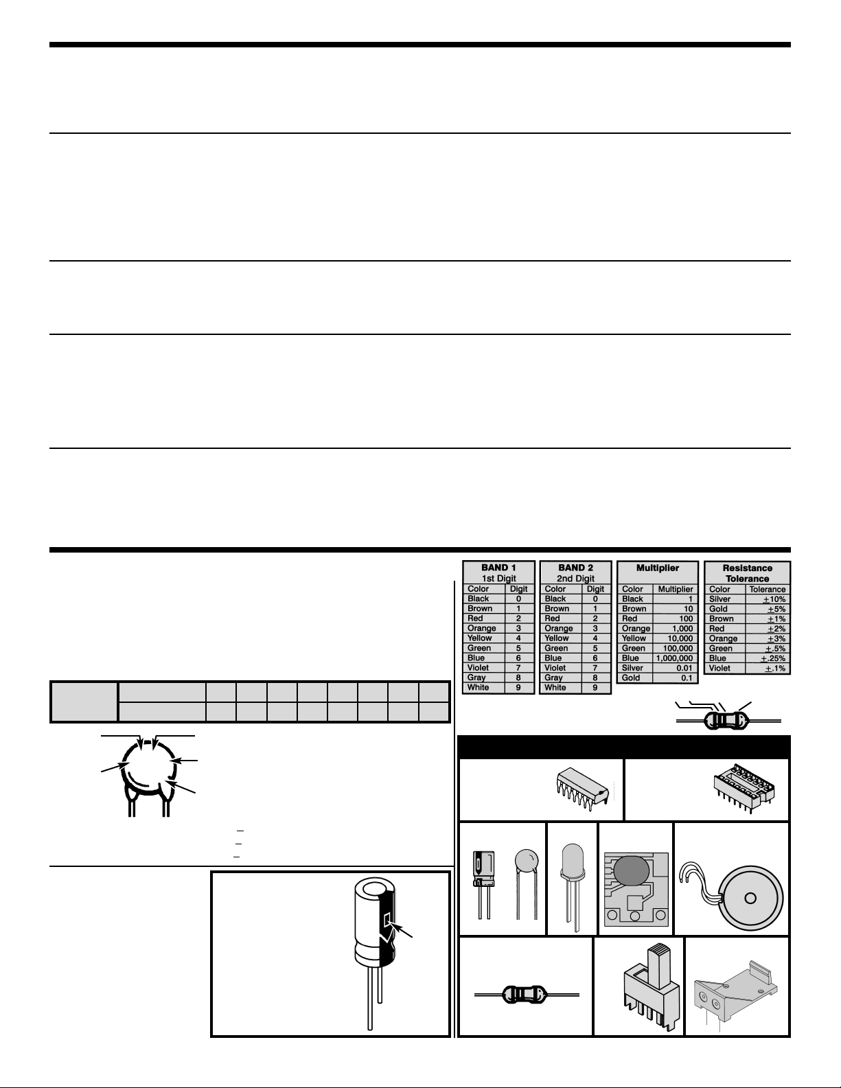
Resistor
PARTS IDENTIFICATION
LED Buzzer with
Wires
Capacitors
Battery Holder
IC Socket
Integrated
Circuit (IC)
Electrolytic
Discap
PCB 3 Melody
Switch
Capacitors will be identified by their capacitance value in pF (picofarads),
nF (nanofarads), or μF (microfarads). Most capacitors will have their
actual value printed on them. Some capacitors may have their value
printed in the following manner. The maximum operating voltage may also
be printed on the capacitor.
Second
digit
First digit
Multiplier
Tolerance*
Note: The letter “R” may be used at
times to signify a decimal point; as
in 3R3 = 3.3
101K
50V
The letter M indicates a tolerance of +20%
The letter K indicates a tolerance of +10%
The letter J indicates a tolerance of +5%
Maximum working voltage
(may or may not appear on the cap)
The value is 10 x 10 =
100pF, ±10%, 50V
*
Warning:
If the capacitor is
connected with
incorrect polarity, it
may heat up and either
leak, or cause the
capacitor to explode.
IDENTIFYING RESISTOR/CAPACITOR VALUES
Multiplier
For the No. 0 1 2 3 4 5 8 9
Multiply By 1 10 100 1k 10k
100k
.01 0.1
Electrolytic capacitors have
a positive and a negative
electrode. The negative
lead is indicated on the
packaging by a stripe with
minus signs and possibly
arrowheads.
Multiplier Tolerance12
Polarity
marking
(+)
(–)
ELECTROLYTIC
CAPACITORS
CERAMIC DISC CAPACITORS (DISCAP)
INTRODUCTION
The Electronic Christmas Tree Kit is a fun project which also gives you the opportunity to learn about the wonderful field
of electronics. The heart of the Electronic Christmas Tree is a 556 integrated circuit. This chip contains two 555 timers which
are very popular in the electronic circuit blocks. The sound of the Electronic Christmas Tree is a special integrated circuit
with a piezoelectric buzzer. You’ll enjoy three charming Christmas melodies: “Jingle Bells”, “Santa Claus is Coming to
Town”, and “We Wish You a Merry Christmas”.
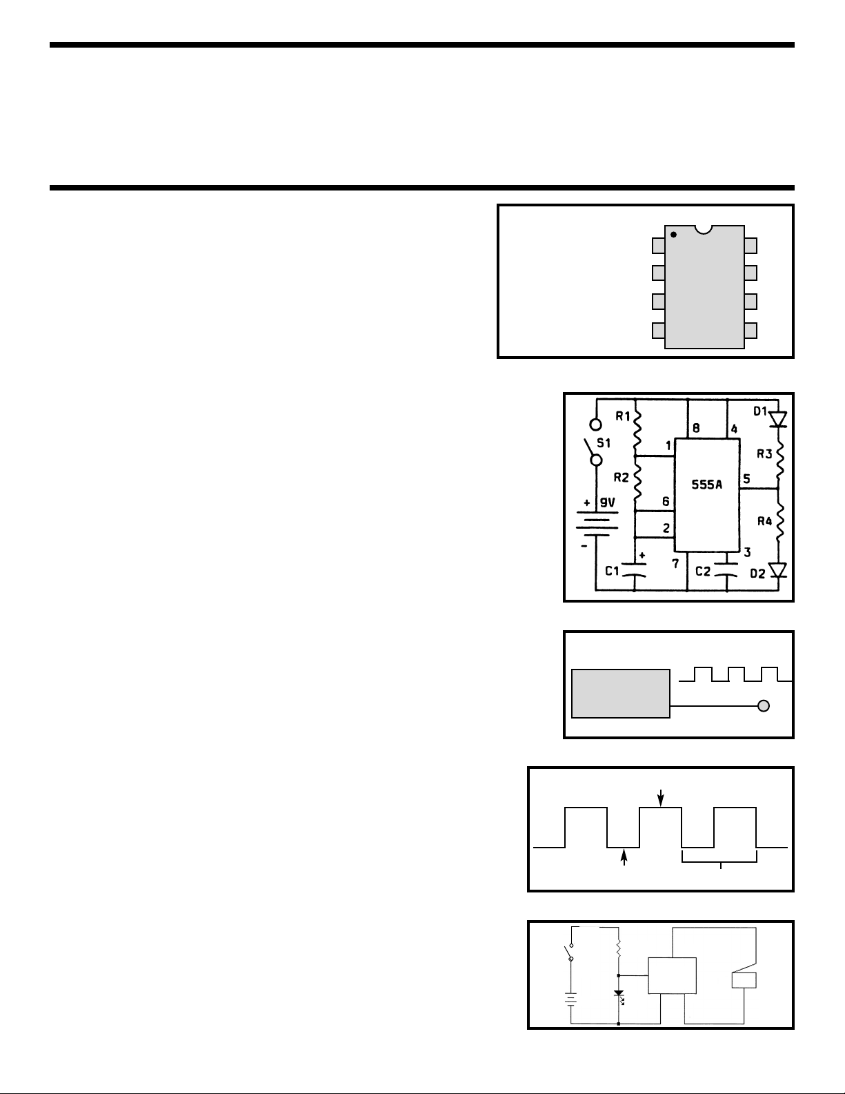
CIRCUIT OPERATION
The 556 timer uses two 555 ICs. Since the Electronic Christmas Tree Kit
contains two 556 timers, there are a total of four 555 timers used in our
circuit. We will confine our analysis to the 555 circuit. The pinout of the
555 is shown in Figure 1.
The basic circuit of the 555 timer as used in the Electronic Christmas
Tree Kit as shown in Figure 2. This circuit is used four times with a slight
variation of components. Refer to the schematic diagram on page 6 to
get a better idea of the total circuit.
The 555 operates in the astable or clock mode. This means that the IC
puts out a series of pulses or oscillations as shown in Figure 3. These pulses are
at the output pin 3, and go high and low in voltage. Note that when the output goes
high, LED D2 will light since there will be about nine volts across R4 and D2. When
the output goes low, LED D1 will light. Thus, the two LEDs will alternately be ON
at the rate determined by the frequency of the oscillator. This frequency is
controlled by the values of capacitor C1 and resistors R1 and R2. This combination
is called an RC time constant. This determines the time constants, the lower the
frequency of oscillation. Thus, if you make the capacitor C1 or resistors R1 and R2
larger in value, the LEDs will take a longer time to flip ON and OFF.
Resistors R1 and R2 determine the duty cycle of the output square wave. The
current charging capacitor C1 goes through resistors R1 and R2. At this time, LED
D2 will be lit. At a certain charge level the IC will react and start discharging C1. The
discharge current will flow only through resistor R2. At this time, LED D1 will be lit.
The difference in charge and discharge time will change the shape of the square
wave as shown in Figure 4.
LED D2 will light a little longer than LED D1. Having the LEDs ON for slightly
different time intervals adds to the flashing effects.
To review what we’ve learned, the values of R1, R2 and C1 determine the output
frequency or how fast the LEDs flash. The relationship between R1 and R2
determines the duty cycle or how long LED D1 will be lit in comparison with LED D2.
The other three 555 timers operate the same except for different values for
R2. Resistors R6, R10 and R14 are each made higher in value, thus each
timer will oscillate at a slightly higher frequency. The blinking rate will be
different for each timer. Capacitors C2, C4, C6 and C8 are added to stabilize
the circuit.
The sound circuit of the Christmas Tree Kit is shown in Figure 5. U3 is a
special integrated circuit. Its memory has three Christmas melodies. These
melodies will repeat all of the time when the switch (S1) is in the ON position.
IC U3 needs to have a power supply of 1.5 - 2V, the same drop voltage as
the LEDs. The piezoelectric buzzer utilizes the principle that crystal material
vibrates when an electric current is imposed upon it.
Figure 1
Figure 2
Figure 3
Figure 4
1
2
3
4
8
7
6
5
1. Ground
2. Trigger
3. Output
4. Reset
5. Control Voltage
6. Threshold
7. Discharge
8. VCC
Square Wave
High
555
Output3
Low
Clock Circuit
Figure 5
On Time of LED-2
On Time of LED-1
1 Cycle
P1
P4
P2
P3
U3
RB
1.2k
S1
SOUND
INTEGRAL
CIRCUIT
D9
9V
BZ
-2-
 Loading...