

Page 1
Instruction Manual
Build
.
Learn
.
Use
www.bigshotcamera.com
Ages 8 - 108 years
Page 2

Contents
Safety
Build
A
Getting Started
B
Power Generator
C
Electronics
D
Lens Wheel
E
LED Flash
Use
P.1
P.2
P.3
P.5
P.8
P.10
A
Camera Parts
B
Charging the Battery
C
Bigshot Software
P.11
P.12
P.13
Page 3

Safety
Always ensure that the camera is operated according to the instructions below, which
are intended to prevent injuries to yourself and other persons, or prevent damage to
the camera.
WARNING: Possibility of serious injury
1. Do not trigger the flash in close proximity to people's eyes. Exposure to the intense
light produced by the flash could damage eyesight. In particular, keep the camera at
least one meter away from infants when using the flash.
2. Store the camera equipment out of reach of children below 8 years. It is dangerous
if any of the components are swallowed. If this occurs, contact a doctor immediately.
Putting the strap around a child's neck could result in asphyxiation.
3. Do not allow liquids to enter the camera. This could result in fire or electric shock.
Do not use organic solvents such as alcohol, benzene, or thinner to clean the camera.
If liquid or foreign objects come into contact with the camera interior, immediately
turn the camera power off.
4. Use only USB outlets to recharge the camera. Use of other power sources could
result in fire or electric shock.
5. The camera's battery is not replaceable. Use of other batteries could result in
explosions, fire or electric shock.
6. Do not place battery near or in direct flame. Do not attempt to disassemble or alter
the battery. Avoid dropping or subjecting battery to severe impacts. In the event that
the battery leaks and the eyes, mouth, skin or clothing contacts these substances,
immediately flush with water and seek medical assistance.
CAUTION: Possibility of injury or damage to the camera
1. Avoid using/storing camera in strong sunlight and high temperatures. These could
cause leakage, overheating or an explosion of the battery resulting in electric shock,
fire, burns and other injuries. High temperatures may also cause deformation of the
camera casing and other components.
2. Do not sit down with the camera in your pocket. Doing so may cause malfunction
or damage the LCD.
3. Do not put the camera and keys or other sharp objects into the same pocket. The
camera lenses or LCD may get scratched.
1
Page 4
Page 5
Build
B
Power Generator
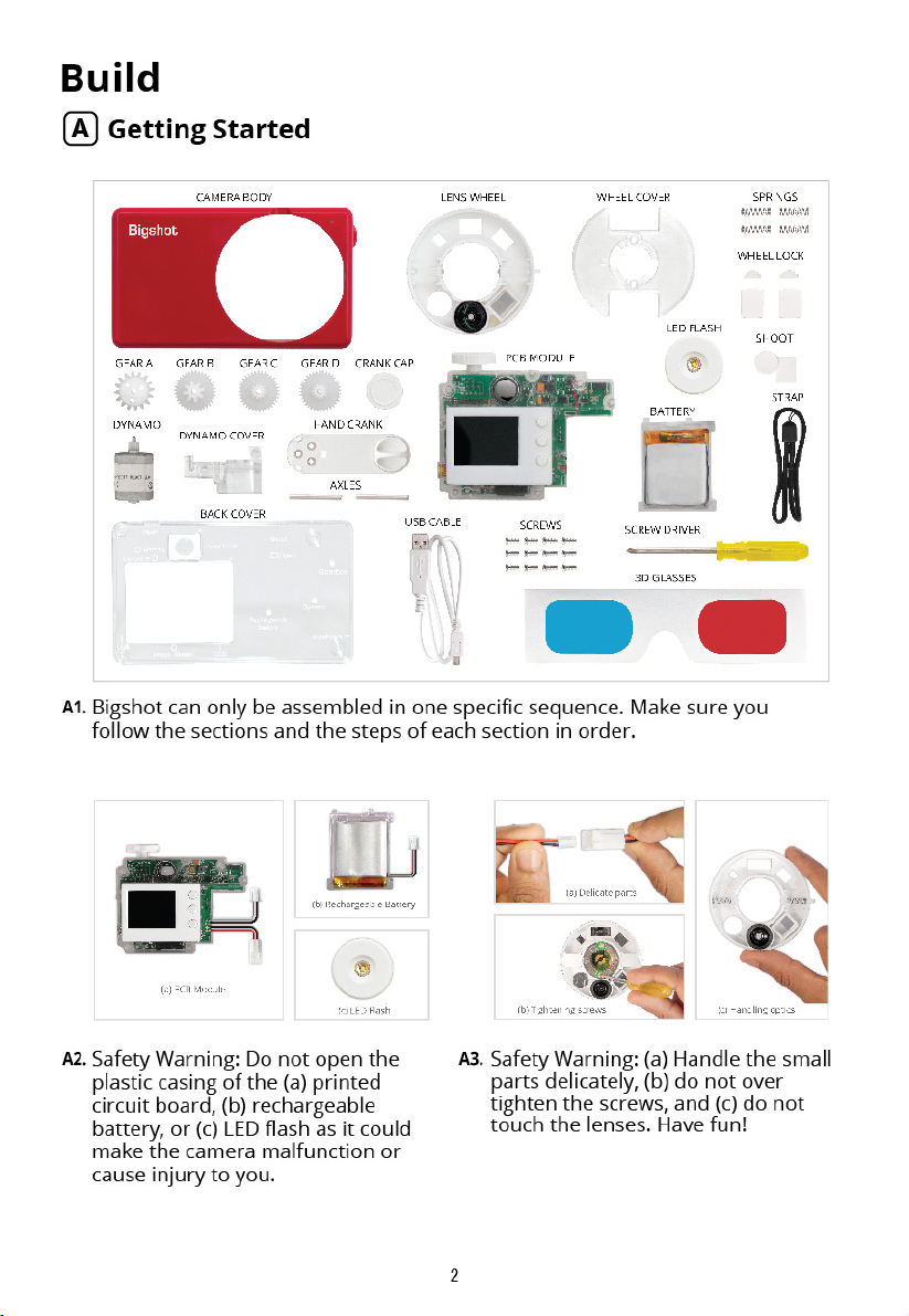
B1.
Slide gear A into the hole on the side
of the camera body. The blue arrow
tells you the direction in which to
slide the gear.
B3.
Place gear C next to the first gear as
shown, and push the rod through
both the gears until it is all the way
in. The left end of the axle should
now sit in the notch on the camera
body and the two gears should be
free to spin.
B2.
While holding the gear in place with
one finger, insert one of the axle rods
into the middle hole of the gear. Push
the rod in until it touches the finger
holding the gear.
B4.
Take gear B and gear D and hold
them together as shown. Now push
the second axle rod through both
gears such that it pops out just a bit
at the other end.
Learn about gears
http://www.bigshotcamera.com/learn/power/gears
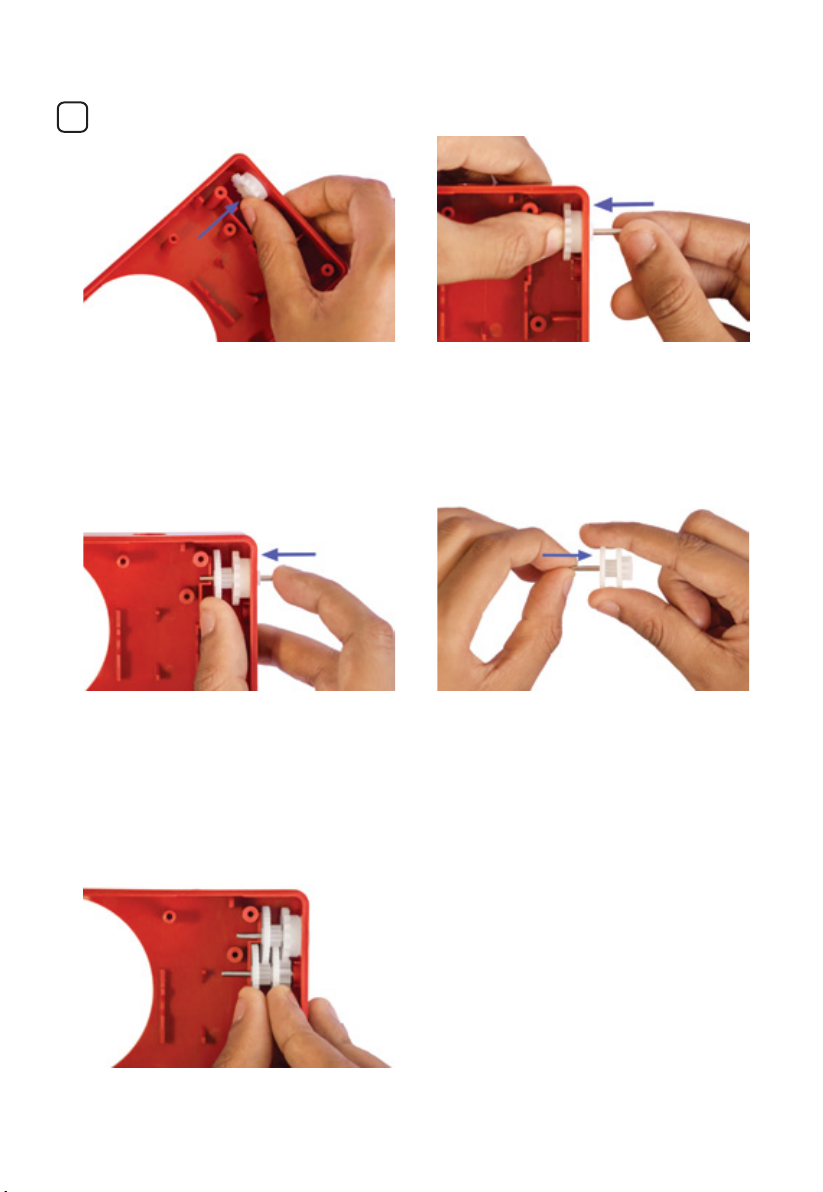
B5.
Take the gear assembly you just
made and place it below the first set
of gears, as shown. Make sure the
left end of the rod rests in the notch
in the camera body.
Learn about gearbox
http://www.bigshotcamera.com/learn/power/gearbox
Page 6

Build
B
Power Generator
B6.
Push the axel rod from the left all
B7.
the way so that it enters the hole
in the camera body on the right.
B8. B9.
Place the bracket on the dynamo so
that it secures the dynamo and the
two axle rods in place.
Place the dynamo into the camera
body. Make sure the dynamo gear
meshes correctly with gear B. Don't try
to rotate any of the gears as it may
cause the axle rods to pop out of their
positions.
Fasten the bracket in place with two
screws, as shown above.
B
10.
Take the hand crank and push-fit its
triangular notch onto the triangular
head of gear A of the gearbox.
Learn about dynamo
http://www.bigshotcamera.com/learn/power/dynamo
B
11.
Fasten the hand crank onto gear A
using three screws, as shown.
Learn about power generator
http://www.bigshotcamera.com/learn/power/index
4 5
Page 7

Build
B
Power Generator
B
12.
Rotate the hand crank clockwise. If
it does not rotate smoothly, one of
the parts of the gearbox may be
misaligned. Carefully undo the
previous steps and reassemble the
gearbox.
Build
B
13.
Clip the white crank cap onto the
hand crank so that it covers the three
screws. Before snapping the cover in
place, make sure you have lined up
the three tabs on the cover with the
slots on the hand crank.
C
Electronics
C1.
Place the shoot button into the hole
on the top face of the camera body.
You will have to insert it at an angle,
as shown.
Learn about power generator
http://www.bigshotcamera.com/learn/power/index
C2.
While the shoot button is in the hole,
rotate its arm clockwise until the arm
slides into the notch on the camera
body.
Learn about electronic components
http://www.bigshotcamera.com/learn/electronics/index
Page 8

Build
C
Electronics
Pick up the PCB module and turn
C3.
C4.
the mode knob to the position
shown above.
C5. C6.
Fasten the PCB module onto the
camera body using three screws.
C7.
Insert the PCB module into the camera
body. Make sure the pillars in the
camera body go through the holes in
the PCB module.
Now set the mode knob to the OFF
position. It must remain in the OFF
position during the remaining
assembly process.
Find the connector attached to the
pair of wires from the PCB that have
the same color combination as the
wires from the dynamo. Hold the two
connectors in each hand and gently
join them until they click.
Learn about electronic components
http://www.bigshotcamera.com/learn/electronics/index
Learn about LCD
http://www.bigshotcamera.com/learn/lcd-display/index
6
Page 9

Build
C
Electronics
C8.
If you want to disconnect the wires,
then press down on the smaller
connector and pull it out as shown
above.
C
10.
Place the connectors from the
dynamo and the battery into the
space at the bottom of the camera
body. Make sure that the wires do
not touch the gears.
C9.
Take the remaining connector from
the PCB module and the connector
from the battery. Gently connect the
connectors so that they click.
C
11.
Now set the battery into the camera
body as shown.
C
12.
Place the clear back cover on top of
the camera body. Make sure the
screw holes on the cover align with
the screw inserts on the camera
body.
C
13.
Fasten the back cover with four
screws.
Learn about rechargeable battery
http://www.bigshotcamera.com/learn/power/battery
7
Page 10

Page 11

Build
D
Lens Wheel
D5.
Now cover the second spring with
the second spring cover.
D7.
After you have attached the lens
wheel, try gently rotating it in each
direction. It should snap into each
of the three lens settings.
D6.
Push-fit the lens wheel into the
casing of the PCB module. Make
sure the two locks on the lens wheel
align correctly with the two notches
on the PCB module, as illustrated by
the blue and purple boxes.
D8.
Place the lens cover on top of the
lens wheel so that the two screw
holes on the cover and the wheel
are aligned.
Learn about the imaging lens
http://www.bigshotcamera.com/learn/imaging-lens/index
D9.
Then, fasten the lens cover with
two screws.
Learn about the stereo prism
http://www.bigshotcamera.com/learn/lens-wheel/stereo
Page 12

Build
E
LED Flash
E1.
Take the LED flash module and
insert it into the PCB module. The
flash module can be inserted in only
one orientation. Make sure that you
match and align the tabs on the
flash module with the notches on
the PCB module (see blue and
purple boxes), before pushing the
flash module into the PCB module.
E3. E4.
The wrist strap has a tiny loop and
a large loop. Squeeze the tiny loop
together and slide it through the
eyelet on the side of the camera
body.
E2.
Turn the LED flash module clockwise
to lock it into the PCB module.
Pass the big loop through the little
loop as shown on the left.
E5.
Then, pull on the big loop to tighten
the strap.
Learn about the LED flash
http://www.bigshotcamera.com/learn/led-flash/index
E6.
Congratulations. You’re done!
10 11
Page 13

Use
A
Camera Parts
Front of the Camera
1
2
Back of the Camera
1
2
3
4
7 8 9
3
1. Shoot button
2. Hand crank
4
3. Mode dial
4. Timer LED
5
5. Lens wheel
6
6. LED flash
7. Regular lens
10
8. Wide Angle lens
9. Stereo/3D prism
10. USB Connector
5
1. Mode dial
2. Viewfinder
3. Display
6
4. USB connector
7
5. Shoot button
8
6. Power indicator
7. Top button
9
8. Middle button
9. Bottom button
Page 14

Use
B
Charging the Battery
Before you start using the camera, you will have to charge the battery. There are two
ways to charge the battery: using a USB charger or using the hand crank. We suggest
you use the first method whenever possible, and reserve the second method for
when you do not have access to a computer.
Using USB charger
Connect the camera to your PC/Mac using
the USB cable provided. Do not use force
or attempt to insert the connectors at an
angle.
The power indicator LED will start blinking
either green (when charge is low) or red
(when charge is extremely low) to indicate
that the camera is charging.
Charging is complete when the power
indicator stops blinking and turns solid
green.
Using hand crank
Turn off the camera by setting the mode
dial to OFF position. Gently rotate the hand
crank clockwise as shown in the figure.
Maintain a speed of 30 to 60 rotations per
minute (rpm). The camera can take one
picture for every 5 to 7 rotations. But it is
better to rotate about 40 times so that
multiple photos can be taken.
Warning: Rotating the hand crank at less than 30rpm will not charge the battery fast
enough. Also, if you try to rotate faster than 60rpm and by applying greater force on
the hand crank, you may damage the gear box.
12 13
Page 15

Use
C
Bigshot Software
Please download Bigshot software from:
www.bigshotcamera.com
Page 16

Build
.
Learn
www.bigshotcamera.com
ScienceTech is a registered trademark of Edu-Science (H.K.) Ltd.
Bigshot is a registered trademark of Kimera LLC, NY.
Copyright
©
2013 Kimera LLC. All rights reserved.
.
Use
P38-EL362-81001000
 Loading...