

Page 1
WARNING: Always check your wiring before
urning o n a c ircuit. Never leave a ci rcuit
t
unatte nded while the batteries are i nstalle d.
ever connect additional batteries or any other
N
power sources to your circuits.
Project 1 Lamp Current Project 2 Batteries in Series
Basic Electricity
Model SCP-10
ARNING: SHOCK HAZARD -
W
Never connect Snap Circuits
to the electrical outlets in your
ome in any way!
h
®
Placement
evel Numbers
1A
Electricity is the movement of sub-atomic charged
particles through a material due to electrical pressure
across the material, such as from a battery. Power
sources, like batteries, push electricity through a circuit,
like a pump pushes water through pipes. Wires carry
electricity, like pipes carry water. Devices like lamps use
the energy in electricity to do things. Switches control the
flow of electricity like valves and faucets control water.
The electrical pressure exerted by a battery or other
power source is called voltage and is measured in volts
(V). The “+” and “–” signs on a battery indicate which
direction it will “pump” electricity.
The electric current is a measure of how fast electricity
is flowing in a wire, just as the water current describes
how fast water is flowing in a pipe. It is expressed in
amperes (A) or milliamps (mA = 1/1,000 of an ampere).
The “power” of electricity is a measure of how fast energy
is moving through a wire. It is a combination of the voltage
and current (Power = Voltage x Current). It is expressed in
watts (W).
The resistance of a component or circuit represents how
much it resists the electrical pressure (voltage) and limits the
flow of electric current. The relationship is Voltage = Current
x Resistance. When resistance increases, less current flows.
Resistance is measured in ohms (W).
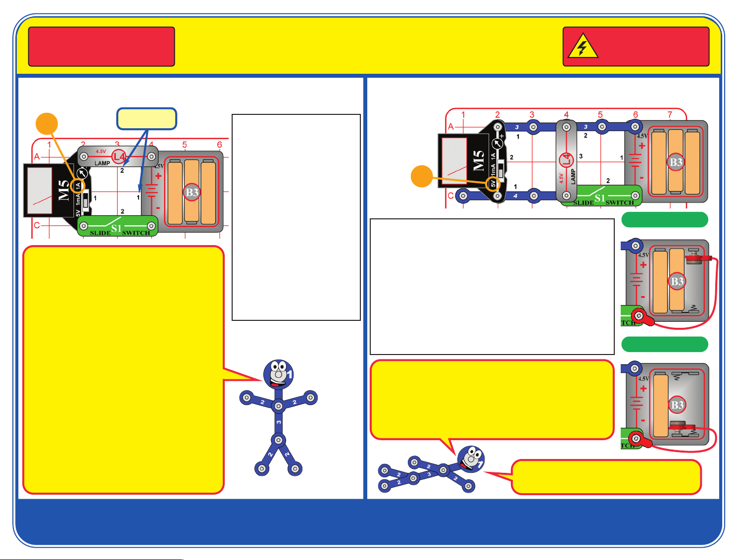
L
Snap Circuits®uses electronic
blocks that snap onto a base
grid to build different circuits.
These blocks have different
colors and numbers on them so
that you can easily identify
them. Build the circuit shown by
placing all the parts with a black
1 next to them on the clear base
grid first. Then, assemble parts
marked with a 2. Install three (3)
“AA” batteries (not included)
into the battery holder (B3).
Set the meter (M5) to the 1A
setting.
Turn on the slide switch (S1).
The lamp (L4) comes on, and
the meter measures how much
electric current is flowing.
5V
Set the meter (M5) to the 5V setting, and turn on the slide
switch (S1). The lamp (L4) comes on, and the meter measures
the voltage from the 3 batteries.
Part B: Remove the left battery from the holder (B3), then snap
one side of the red jumper jumper on as shown, and touch
metal on the other end to the left spring in the battery holder.
Read the voltage on the meter, measuring 2 batteries, and
notice how the lamp is dimmer.
Part C: Now also remove the center battery from the holder and
touch metal on the end of the red jumper wire to the center
spring in the holder. Read the voltage on the meter, measuring
1 battery, and notice how the lamp is dimmer.
If desired, use the voltage measured here (with 3 batteries) and the
current measured in project 1 to calculate the resistance and power of
the lamp:
Resistance equals Voltage divided by Current, and should be about 15
ohms. Power equals Voltage times Current, and should be about 1 Watt.
Your results may be different, because M5 is a simple meter with low
accuracy, and your battery voltage can vary.
Batteries are like electrical pressure, pushing electricity
through a circuit. Adding more batteries increases the
flow of electricity, making the lamp brighter.
Part B:
Part C:
Quiz answers:
1. B 2. B 3. C 4. A 5. B
If you have any problems, contact Elenco
®
Copyright © 2014 Elenco®Electronics, Inc. All Rights Reserved. ● 150 Carpenter Ave. ● Wheeling, IL 60090
(800) 533-2441 Fax: (847) 520-0085 ● e-mail: elenco@elenco.com ● Website: www.elenco.com or www.snapcircuits.net
753159
Page 2
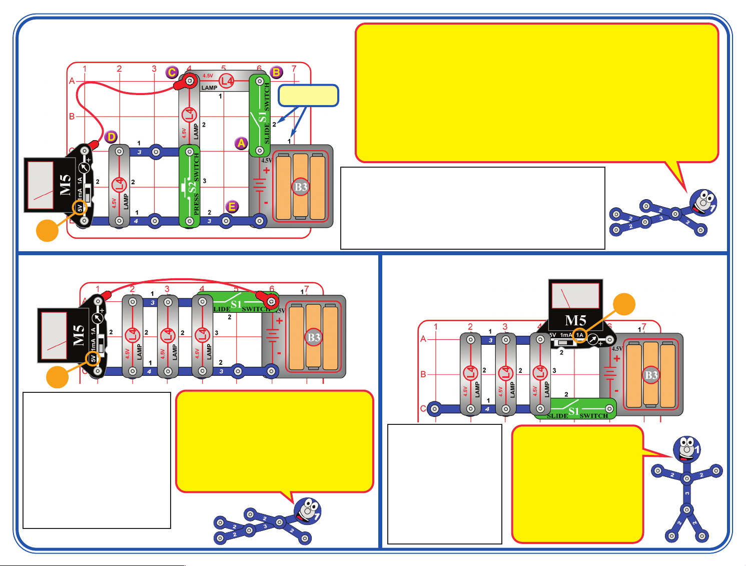
Project 3 Triple Voltage Divider
Placement
evel Numbers
L
5V
The circuit has three lamps connected in series, or two when S2 is pressed (S2 bypasses the last one).
A. Point A is the “+” battery terminal, so the meter is always measuring the battery voltage.
. When S1 is on, point B is connected to the batteries, so the voltage will be the same as point A. When
B
S1 is off, the voltage is zero.
C. Point C measures the voltage after one lamp and across the other two, so should be about 2/3 of the
battery voltage. When S2 is pressed, the last lamp is bypassed, so point C is measuring across one of
he two remaining lamps, so should be approximately 1/2 of the battery voltage.
t
. Point D measures the voltage after two lamps and across the last one, so should be about 1/3 of the
D
battery voltage. When S2 is pressed, the last lamp is bypassed, so point D is zero volts just like point E.
E. Point E is the “—” battery terminal, and will always be zero.
Kirchhoff’s Voltage Law, an important rule for analyzing circuits, says the total voltage driving a circuit must
equal the voltage drops within it. So the voltage drops across all of the lamps should equal the battery
voltage. (Your measurements may be a little different, because M5 is a simple meter with low accuracy.)
This circuit is pictured on the front of the box, use that picture to help
in building it. Set the meter (M5) to the 5V setting. Turn on the slide
switch (S1) and use the meter to measure the voltage at points A, B,
C, D, & E in the circuit by connecting the end of the red jumper wire
to each of those points (the drawing shows it connected to point C).
Next, repeat the voltage measurements at points A, B, C, D, & E
while pushing the press switch (S2).
Project 4 Heavy Load
5V
Set the meter (M5) to the 5V setting,
and initially keep the switch (S1) off.
The meter measures the battery
voltage with the lamps (L4) off.
Now turn the switch on to light the
lamps, and see if the battery voltage
changes. Next, remove one or two of
the lamps and compare the voltage.
Try this project with both new strong
batteries and with old weak ones.
Compare how the voltage changes
when you turn the switch on.
Batteries produce electricity using a chemical reaction,
and only a limited amount of the chemicals can react
together at once. Also, the chemical reaction slows as the
batteries get weaker. When a circuit wants more
electricity than the batteries can supply, the voltage
(electrical pressure) drops.
In this circuit, lighting all three lamps takes a lot of
electricity, so the voltage drops a little when the switch is
turned on. The drop in voltage is much greater for weak
old batteries than for strong new ones.
Project 5 Heavy Flow
Modify the preceding circuit
to match this one. Set the
meter (M5) to the 1A setting
and turn on the switch (S1).
The meter measures the
current. Try removing one
or two lamps and see how
the current changes. Also
try this circuit with both new
strong batteries and with old
weak ones.
1A
In this circuit, electricity flows out
of the batteries, through the meter,
then divides among the 3 lamps,
then all flows back to the batteries
through the switch.
The 3 lamps are connected in
parallel, because the current flow
divides among them. If one of the
lamps burns out, the others will
still work because has its own path
for electricity to flow along.
Page 3

1A
Set the meter (M5) to the 1A setting and turn on the switch (S1). The
lamps light and the meter measures the electric current flow. Try
rearranging the parts in the circuit (keeping the “+” side of the meter
aligned with the “+” side of the batteries) and how it affects the circuit.
Next, try replacing any of the lamps (L4) with the press switch (S2)
and push it.
Project 6 Loop
Project 7 Find Your Own Parts
Build the circuit shown; the can be
anything you want. Set the meter (M5) to
the 1A setting and turn on the switch
1A
?
(S1). Touch various materials between
the snaps on the 4-snap wire and
batttery holder “—” side. Use the red
jumper wire to help make a connection if
needed. See which materials are good
at transporting electricity by watching the
meter current and lamp (L4) brightness.
If the meter reads zero, switch it to the
1mA setting to see if there is just a very
small current. With the 1mA meter
setting, try placing two of your fingers
across the snaps to see how well you
transport electricity; wet your fingers to
get better electrical contact. To help
protect the meter, always switch back to
the 1A scale before testing a new circuit.
This circuit has the lamps connected in
series (not in parallel, as in project 5).
a
This arrangement makes the lamps
dimmer because the battery voltage is
ivided among the 3 lamps, but also
d
makes the batteries last longer
because less current is flowing.
lectricity from the batteries flows in a
E
loop, equally through each component
in the circuit.
Rearranging the components in a
series circuit does not change it,
because the same amount of electricity
is flowing through each component.
Replacing one of the lamps with the
press switch increases the current,
because the pressed switch has no
resistance to the flow of electricity.
If several lamps are arranged in series
and one burns out, none will work
because the only path for electricity is
blocked.
?
Project 8
Fast Bright, Slow Dim
5V
Part A: Set the meter (M5) to the 5V setting. Push the press switch (S2)
for several seconds, while watching the meter. The meter is measuring
the voltage across the two left lamps (labeled A & B); its reading jumps
up when the switch is pressed, then slowly rises more for a few
seconds. Push the switch again while closely watching the lamps A &
B. Notice how lamps A & B initially are off, but turn on dimly within a
second or two.
Note: The voltage measured in this step will be small; in some cases in
may even be too small to measure with your M5 meter. M5 is a simple
meter, don’t expect it to be as accurate as normal electronic test
instruments.
Part B: Remove lamp B, and push the switch again. Now both
remaining lamps (A & C) get equally bright fast, and the meter shows a
higher voltage across the left lamp (A).
Part C: Replace the right lamp (C) with a 3-snap wire, and push the
switch again. Now the left lamp (A) gets the full battery voltage, as
shown on the meter.
Incandescent light bulbs, like those in the L4 lamps, make
light by passing a big electric current through a special
resistive wire (the filament), which gets so hot that it glows.
The two left bulbs (A & B) get less current than the right bulb
(C) so they take longer to heat up and don’t get as hot.
The meter measures the voltage cross left lamps A & B.
This voltage will be low when the left lamps are dim. When
you remove lamp B, both remaining lamps have the same
voltage across them and the same current through them.
In part A, you might have expected left lamps A & B to be
half as bright as the right lamp (C), because the current
through lamp C should divide equally between lamps A & B,
but instead lamps A & B are much dimmer. This occurs
because bulb filaments offer less resistance to the flow of
electricity when they are cold, and increase in resistance as
they heat up. Your L4 lamps have resistance of less than 5
ohms when they are cold, and about 15 ohms then bright.
Page 4

Project 9 Current Divider
PARTS LIST
1A
Set the meter (M5) to the 1A setting, and push the press switch (S2). The lamps (L4)
come on, and the meter measures the current from the batteries.
Part B: Swap the location of the meter with the 3-snap wire marked “A” (place “+” side
towards L4). Push the switch to measure the current through circuit branch “A”.
Part C: Swap the “A” location of the meter with the “B” 3-snap. Note that M5 will not fit;
just hold it in place for this test. Push the switch to measure the current the “B” branch.
The current from the batteries splits up between the
two lamps, because they are connected in parallel.
If you add up the current you measured through
circuit branches A & B, it should be the same as the
current you measured from the batteries. (Your
result may be a little different, because M5 is a
simple meter with low accuracy.)
Kirchhoff’s Current Law, an important rule for
analyzing circuits, says that all current flowing into a
point must flow out of it.
M5 will not fit, so
ust hold it in place.
j
Quick Quiz: (answers on bottom left of page 1)
Part B: Part C:
1. __________ is a
measure of has fast
electricity is flowing in
a circuit.
A. Voltage
B. Current
C. Power
D. Watts
Snap Circuits®has many other fun and educational products. For a listing of local retailers who carry Snap Circuits®visit
www.elenco.com or call us toll-free at 800-533-2441. For information about our other Snap Circuits
additional parts visit www.snapcircuits.net.
2. When several lamps
are wired in
_____________ with
each other, all will
have the same
electric current flowing through them.
A. Parallel
B. Series
C. Both A & B
D. Neither A nor B
3. Batteries produce
electricity using a
_________________
reaction.
A. Nuclear
B. Hydrothermal
C. Chemical
D. Biological
4. Resistance is
________________.
A. Voltage divided
by current
B. Power times
voltage
C. Expressed in
amperes
D. Never important
in electrical
circuits
5. An incandescent light
bulb filament has
_________________
resistance when it is
cold than when it is
hot.
A. More
B. Less
C. Equal
D. All of the above
®
kits, accessories, and
Qty. ID Name Part #
r 2 3 3-snap wire 6SC03
r 1 4 4-snap wire 6SC04
r 1 B3 Battery holder 6SCB3
r 1 Base grid 6SCBGMF
r 1 Red jumper wire 6SCJ2
r 3 L4 4.5V Lamp 6SCL4
r 1 M5 Meter 6SCM5
r 1 S1 Slide switch 6SCS1
r 1 S2 Press switch 6SCS2
Important: If any parts are missing or
damaged, DO NOT RETURN TO
RETAILER. Call toll-free (800) 533-2441 or
e-mail us at: help@elenco.com.
Customer Service ● 150 Carpenter Ave. ●
Wheeling, IL 60090 U.S.A.
You may order additional / replacement
parts at our website: www.snapcircuits.net
BATTERIES:
● Use only 1.5V AA type (alkaline
recommended, not included).
● Insert batteries with correct polarity.
● Non-rechargeable batteries should not
be recharged. Rechargeable batteries
should only be charged under adult
supervision, and should not be
recharged while in the product.
● Do not mix alkaline, standard (carbonzinc), or rechargeable (nickelcadmium) batteries.
● Do not mix old and new batteries.
Remove batteries when they are used up.
●
● Do not short circuit the battery
terminals.
● Never throw batteries in a fire or
attempt to open its outer casing.
● Batteries are harmful if swallowed, so
keep away from small children.
 Loading...